JP4960627B2 - Transmission module for variable torque distribution and motor vehicle equipped with the transmission module - Google Patents
Transmission module for variable torque distribution and motor vehicle equipped with the transmission module Download PDFInfo
- Publication number
- JP4960627B2 JP4960627B2 JP2005362147A JP2005362147A JP4960627B2 JP 4960627 B2 JP4960627 B2 JP 4960627B2 JP 2005362147 A JP2005362147 A JP 2005362147A JP 2005362147 A JP2005362147 A JP 2005362147A JP 4960627 B2 JP4960627 B2 JP 4960627B2
- Authority
- JP
- Japan
- Prior art keywords
- shaft
- differential
- transmission
- housing
- transmission module
- Prior art date
- Legal status (The legal status is an assumption and is not a legal conclusion. Google has not performed a legal analysis and makes no representation as to the accuracy of the status listed.)
- Active
Links
- 230000005540 biological transmission Effects 0.000 title claims description 173
- 238000009826 distribution Methods 0.000 title claims description 21
- 210000004513 dentition Anatomy 0.000 claims description 10
- 230000036346 tooth eruption Effects 0.000 claims description 10
- 230000002093 peripheral effect Effects 0.000 claims description 5
- 239000000314 lubricant Substances 0.000 description 10
- 230000008878 coupling Effects 0.000 description 9
- 238000010168 coupling process Methods 0.000 description 9
- 238000005859 coupling reaction Methods 0.000 description 9
- 239000000470 constituent Substances 0.000 description 8
- 238000005096 rolling process Methods 0.000 description 5
- 238000007789 sealing Methods 0.000 description 4
- 238000004519 manufacturing process Methods 0.000 description 3
- 239000002184 metal Substances 0.000 description 3
- 230000006978 adaptation Effects 0.000 description 2
- 238000001816 cooling Methods 0.000 description 2
- 239000000725 suspension Substances 0.000 description 2
- 230000004323 axial length Effects 0.000 description 1
- 230000015572 biosynthetic process Effects 0.000 description 1
- 239000000969 carrier Substances 0.000 description 1
- 230000000295 complement effect Effects 0.000 description 1
- 230000000694 effects Effects 0.000 description 1
- 230000037431 insertion Effects 0.000 description 1
- 238000003780 insertion Methods 0.000 description 1
- 239000010687 lubricating oil Substances 0.000 description 1
- 238000005461 lubrication Methods 0.000 description 1
- 238000003825 pressing Methods 0.000 description 1
Images


Classifications
-
- F—MECHANICAL ENGINEERING; LIGHTING; HEATING; WEAPONS; BLASTING
- F16—ENGINEERING ELEMENTS AND UNITS; GENERAL MEASURES FOR PRODUCING AND MAINTAINING EFFECTIVE FUNCTIONING OF MACHINES OR INSTALLATIONS; THERMAL INSULATION IN GENERAL
- F16H—GEARING
- F16H48/00—Differential gearings
- F16H48/20—Arrangements for suppressing or influencing the differential action, e.g. locking devices
- F16H48/295—Arrangements for suppressing or influencing the differential action, e.g. locking devices using multiple means for force boosting
-
- B—PERFORMING OPERATIONS; TRANSPORTING
- B60—VEHICLES IN GENERAL
- B60K—ARRANGEMENT OR MOUNTING OF PROPULSION UNITS OR OF TRANSMISSIONS IN VEHICLES; ARRANGEMENT OR MOUNTING OF PLURAL DIVERSE PRIME-MOVERS IN VEHICLES; AUXILIARY DRIVES FOR VEHICLES; INSTRUMENTATION OR DASHBOARDS FOR VEHICLES; ARRANGEMENTS IN CONNECTION WITH COOLING, AIR INTAKE, GAS EXHAUST OR FUEL SUPPLY OF PROPULSION UNITS IN VEHICLES
- B60K17/00—Arrangement or mounting of transmissions in vehicles
- B60K17/04—Arrangement or mounting of transmissions in vehicles characterised by arrangement, location, or kind of gearing
- B60K17/16—Arrangement or mounting of transmissions in vehicles characterised by arrangement, location, or kind of gearing of differential gearing
- B60K17/165—Arrangement or mounting of transmissions in vehicles characterised by arrangement, location, or kind of gearing of differential gearing provided between independent half axles
-
- B—PERFORMING OPERATIONS; TRANSPORTING
- B60—VEHICLES IN GENERAL
- B60K—ARRANGEMENT OR MOUNTING OF PROPULSION UNITS OR OF TRANSMISSIONS IN VEHICLES; ARRANGEMENT OR MOUNTING OF PLURAL DIVERSE PRIME-MOVERS IN VEHICLES; AUXILIARY DRIVES FOR VEHICLES; INSTRUMENTATION OR DASHBOARDS FOR VEHICLES; ARRANGEMENTS IN CONNECTION WITH COOLING, AIR INTAKE, GAS EXHAUST OR FUEL SUPPLY OF PROPULSION UNITS IN VEHICLES
- B60K17/00—Arrangement or mounting of transmissions in vehicles
- B60K17/34—Arrangement or mounting of transmissions in vehicles for driving both front and rear wheels, e.g. four wheel drive vehicles
- B60K17/344—Arrangement or mounting of transmissions in vehicles for driving both front and rear wheels, e.g. four wheel drive vehicles having a transfer gear
- B60K17/346—Arrangement or mounting of transmissions in vehicles for driving both front and rear wheels, e.g. four wheel drive vehicles having a transfer gear the transfer gear being a differential gear
- B60K17/3462—Arrangement or mounting of transmissions in vehicles for driving both front and rear wheels, e.g. four wheel drive vehicles having a transfer gear the transfer gear being a differential gear with means for changing distribution of torque between front and rear wheels
-
- B—PERFORMING OPERATIONS; TRANSPORTING
- B60—VEHICLES IN GENERAL
- B60K—ARRANGEMENT OR MOUNTING OF PROPULSION UNITS OR OF TRANSMISSIONS IN VEHICLES; ARRANGEMENT OR MOUNTING OF PLURAL DIVERSE PRIME-MOVERS IN VEHICLES; AUXILIARY DRIVES FOR VEHICLES; INSTRUMENTATION OR DASHBOARDS FOR VEHICLES; ARRANGEMENTS IN CONNECTION WITH COOLING, AIR INTAKE, GAS EXHAUST OR FUEL SUPPLY OF PROPULSION UNITS IN VEHICLES
- B60K23/00—Arrangement or mounting of control devices for vehicle transmissions, or parts thereof, not otherwise provided for
- B60K23/08—Arrangement or mounting of control devices for vehicle transmissions, or parts thereof, not otherwise provided for for changing number of driven wheels, for switching from driving one axle to driving two or more axles
- B60K23/0808—Arrangement or mounting of control devices for vehicle transmissions, or parts thereof, not otherwise provided for for changing number of driven wheels, for switching from driving one axle to driving two or more axles for varying torque distribution between driven axles, e.g. by transfer clutch
-
- F—MECHANICAL ENGINEERING; LIGHTING; HEATING; WEAPONS; BLASTING
- F16—ENGINEERING ELEMENTS AND UNITS; GENERAL MEASURES FOR PRODUCING AND MAINTAINING EFFECTIVE FUNCTIONING OF MACHINES OR INSTALLATIONS; THERMAL INSULATION IN GENERAL
- F16H—GEARING
- F16H48/00—Differential gearings
- F16H48/06—Differential gearings with gears having orbital motion
- F16H48/08—Differential gearings with gears having orbital motion comprising bevel gears
-
- F—MECHANICAL ENGINEERING; LIGHTING; HEATING; WEAPONS; BLASTING
- F16—ENGINEERING ELEMENTS AND UNITS; GENERAL MEASURES FOR PRODUCING AND MAINTAINING EFFECTIVE FUNCTIONING OF MACHINES OR INSTALLATIONS; THERMAL INSULATION IN GENERAL
- F16H—GEARING
- F16H48/00—Differential gearings
- F16H48/06—Differential gearings with gears having orbital motion
- F16H48/10—Differential gearings with gears having orbital motion with orbital spur gears
-
- F—MECHANICAL ENGINEERING; LIGHTING; HEATING; WEAPONS; BLASTING
- F16—ENGINEERING ELEMENTS AND UNITS; GENERAL MEASURES FOR PRODUCING AND MAINTAINING EFFECTIVE FUNCTIONING OF MACHINES OR INSTALLATIONS; THERMAL INSULATION IN GENERAL
- F16H—GEARING
- F16H48/00—Differential gearings
- F16H48/20—Arrangements for suppressing or influencing the differential action, e.g. locking devices
- F16H48/30—Arrangements for suppressing or influencing the differential action, e.g. locking devices using externally-actuatable means
- F16H48/34—Arrangements for suppressing or influencing the differential action, e.g. locking devices using externally-actuatable means using electromagnetic or electric actuators
-
- F—MECHANICAL ENGINEERING; LIGHTING; HEATING; WEAPONS; BLASTING
- F16—ENGINEERING ELEMENTS AND UNITS; GENERAL MEASURES FOR PRODUCING AND MAINTAINING EFFECTIVE FUNCTIONING OF MACHINES OR INSTALLATIONS; THERMAL INSULATION IN GENERAL
- F16H—GEARING
- F16H48/00—Differential gearings
- F16H48/06—Differential gearings with gears having orbital motion
- F16H48/10—Differential gearings with gears having orbital motion with orbital spur gears
- F16H2048/106—Differential gearings with gears having orbital motion with orbital spur gears characterised by two sun gears
-
- F—MECHANICAL ENGINEERING; LIGHTING; HEATING; WEAPONS; BLASTING
- F16—ENGINEERING ELEMENTS AND UNITS; GENERAL MEASURES FOR PRODUCING AND MAINTAINING EFFECTIVE FUNCTIONING OF MACHINES OR INSTALLATIONS; THERMAL INSULATION IN GENERAL
- F16H—GEARING
- F16H48/00—Differential gearings
- F16H48/20—Arrangements for suppressing or influencing the differential action, e.g. locking devices
- F16H2048/204—Control of arrangements for suppressing differential actions
-
- F—MECHANICAL ENGINEERING; LIGHTING; HEATING; WEAPONS; BLASTING
- F16—ENGINEERING ELEMENTS AND UNITS; GENERAL MEASURES FOR PRODUCING AND MAINTAINING EFFECTIVE FUNCTIONING OF MACHINES OR INSTALLATIONS; THERMAL INSULATION IN GENERAL
- F16H—GEARING
- F16H48/00—Differential gearings
- F16H48/20—Arrangements for suppressing or influencing the differential action, e.g. locking devices
- F16H48/30—Arrangements for suppressing or influencing the differential action, e.g. locking devices using externally-actuatable means
- F16H48/34—Arrangements for suppressing or influencing the differential action, e.g. locking devices using externally-actuatable means using electromagnetic or electric actuators
- F16H2048/343—Arrangements for suppressing or influencing the differential action, e.g. locking devices using externally-actuatable means using electromagnetic or electric actuators using a rotary motor
-
- F—MECHANICAL ENGINEERING; LIGHTING; HEATING; WEAPONS; BLASTING
- F16—ENGINEERING ELEMENTS AND UNITS; GENERAL MEASURES FOR PRODUCING AND MAINTAINING EFFECTIVE FUNCTIONING OF MACHINES OR INSTALLATIONS; THERMAL INSULATION IN GENERAL
- F16H—GEARING
- F16H48/00—Differential gearings
- F16H48/38—Constructional details
- F16H2048/382—Methods for manufacturing differential gearings
-
- F—MECHANICAL ENGINEERING; LIGHTING; HEATING; WEAPONS; BLASTING
- F16—ENGINEERING ELEMENTS AND UNITS; GENERAL MEASURES FOR PRODUCING AND MAINTAINING EFFECTIVE FUNCTIONING OF MACHINES OR INSTALLATIONS; THERMAL INSULATION IN GENERAL
- F16H—GEARING
- F16H48/00—Differential gearings
- F16H48/20—Arrangements for suppressing or influencing the differential action, e.g. locking devices
- F16H48/22—Arrangements for suppressing or influencing the differential action, e.g. locking devices using friction clutches or brakes
Description
本発明は、自動車のパワートレーンにおける可変のトルク分配のための伝動装置モジュールに関する。 The present invention relates to a transmission module for variable torque distribution in an automobile power train.
このような形式の伝動装置ユニットは、一般的に1つの入力軸と、相補作用を有する2つの出力軸とを備えた差動装置を有している。可変のトルク分配のための伝動装置ユニットの機能形式によれば、入力軸を介して導入されるトルクの一部が、両方の出力軸に分配されるまえに差動装置ケースによって分岐され、分岐されたトルク成分は、残りのトルクの分配の後方で、両方の出力軸の一方に追加的に及ぼされる。このために各出力軸に伝動装置段ならびにクラッチが設けられている。伝動装置段は差動装置ケースによって駆動される入力歯車を備えており、入力歯車は出力歯車を加速または減速する。出力歯車を差動装置の該当する出力軸に連結することによって、出力軸は加速または減速される。必要に応じて両方の出力軸のうちの一方に、別の一方よりも大きなトルクを伝達することができ、これによって自動車の走行安定性を高めることができる。そのような伝動装置ユニットは、軸差動装置の両方の車軸の間でトルクを分配するため、または多軸駆動式の自動車の中央差動装置の両方のシャフトの間でトルクを分配制御するために使用することができる。 A transmission unit of this type generally has a differential device with one input shaft and two output shafts having complementary action. According to the functional form of the transmission unit for variable torque distribution, a part of the torque introduced via the input shaft is branched by the differential case before being distributed to both output shafts. The applied torque component is additionally exerted on one of both output shafts behind the remaining torque distribution. For this purpose, each output shaft is provided with a transmission stage and a clutch. The transmission stage includes an input gear driven by a differential case, which accelerates or decelerates the output gear. By connecting the output gear to the corresponding output shaft of the differential, the output shaft is accelerated or decelerated. If necessary, a torque larger than that of the other output shaft can be transmitted to one of the two output shafts, thereby improving the running stability of the automobile. Such a transmission unit distributes torque between both axles of a shaft differential or to distribute torque between both shafts of a central differential of a multi-axis drive vehicle Can be used for
欧州特許第844416号明細書から、自動車のパワートレーンのための伝動装置ユニットが公知であり、伝動装置ユニットは、2つの出力軸の間のアクティブ、つまり制御式の可変のトルク分配を実現する。伝動装置ユニットは、差動装置ケースと、差動装置ケース内で回動可能に支承された2つのサイド歯車とを備えた差動伝動装置を有しており、サイド歯車は、差動装置ケースと共に回転する差動歯車を介して駆動される。両方の車軸にそれぞれキャリアが支承されており、キャリアは伝動装置段を支持する。伝動装置段は、複数の遊星歯車を備えており、遊星歯車は第1の歯列区分で、差動装置ケースと相対回動不能に結合されていて、かつ第2の歯列区分で、車軸と堅固に結合された太陽歯車に噛み合う。各車軸に多板クラッチが設けられており、多板クラッチは伝動装置ハウジングに対するキャリアの回動を制動するのに役立つ。このようにして適当な車軸に追加的なトルクが及ぼされる。 From EP 844416 a transmission unit for a motor vehicle powertrain is known, which implements an active, ie controlled, variable torque distribution between two output shafts. The transmission device unit has a differential transmission device including a differential device case and two side gears rotatably supported in the differential device case. It is driven through a differential gear that rotates together with it. A carrier is supported on both axles, and the carrier supports the gear stage. The transmission stage includes a plurality of planetary gears, the planetary gears being connected to the differential case in a non-rotatable manner in the first dentition section, and in the second dentition section, the axle. And mesh with the tightly coupled sun gear. Each axle is provided with a multi-plate clutch, which serves to brake the rotation of the carrier relative to the transmission housing. In this way, additional torque is exerted on the appropriate axle.
ドイツ連邦共和国特許出願公開第19524547号明細書から、別の差動装置ユニットが公知であり、差動装置ユニットは第1の出力軸と第2の出力軸との間のアクティブなトルク制御を実現する。差動装置ユニットは、遊星差動装置、キャリアを有する伝動装置段ならびに2つのクラッチを備えている。クラッチは、相並んで配置されていて、かつ縦置きの伝動装置ハウジングに対して支持されている。クラッチの1つはキャリアを制動するのに役立ち、その結果追加的なトルクが第1の出力軸に伝達される。クラッチの別1つは第1の出力軸を制動するのに役立ち、その結果追加的なトルクが第2の出力軸に伝達される。全体として差動装置ユニットの構造は比較的複雑になっている。
From
ドイツ連邦共和国特許出願公開第10342164号明細書から、自動車のパワートレーンにおけるアクティブなトルク制御のための別の伝動装置ユニットが公知である。ここでは差動装置ケースを備えた差動装置が設けられており、差動装置ケースは、伝動装置段を介して多板クラッチの2つのクラッチケースを駆動する。伝動装置段は、伝達が迅速に行われるように形成されているので、両方のクラッチのうちの一方の閉鎖によって、該当する出力軸に追加的にトルクを及ぼすことができる。
したがって本発明の課題は、冒頭で述べたような形式の、可変のトルク分配を有する伝動装置モジュールを改良して、簡単な構造を有していて、かつ簡単に組立可能なものを提供することである。 Accordingly, an object of the present invention is to provide an improved transmission module with variable torque distribution of the type described at the outset, which has a simple structure and can be easily assembled. It is.
この課題を解決するための本発明の装置によれば、自動車のパワートレーンにおける可変のトルク分配のための伝動装置モジュールにおいて、第1の軸が設けられており、該第1の軸が、回転軸線を中心に縦置きのハウジングに対して回動可能に支承されており、該第1の軸に対して同軸的に配置された第2の軸が設けられており、該第2の軸が、第1の軸と駆動結合されており、少なくとも1つの遊星歯車と、少なくとも1つの遊星歯車を支持するキャリアとを備えた、第1の軸と第2の軸との間のトルク流れ経路に配置された伝動装置段が設けられており、キャリアが、回転軸線を中心に回転可能に形成されており、クラッチが設けられており、該クラッチが、ハウジングに支持されていて、かつハウジングに対してキャリアを連結するのに役立ち、ハウジングに対してキャリアを連結することによって、第1および第2の軸のうちの一方から、第1および第2の軸のうちの別の一方へのトルク伝達が行われるようになっており、ハウジング、第1の軸、第2の軸、伝動装置段およびクラッチが、1構成ユニットの一部を成しており、ハウジングに接続手段が設けられており、構成ユニットが伝動装置に接続されるようになっている。 According to the apparatus of the present invention for solving this problem, a first shaft is provided in a transmission module for variable torque distribution in a power train of an automobile, and the first shaft rotates. A second shaft is provided so as to be rotatable with respect to the longitudinal housing about the axis, and is disposed coaxially with the first shaft. The second shaft is In a torque flow path between the first shaft and the second shaft, the drive shaft being coupled to the first shaft and comprising at least one planetary gear and a carrier supporting the at least one planetary gear. A transmission gear stage is provided, the carrier is formed to be rotatable about a rotational axis, a clutch is provided, the clutch is supported by the housing and is Link carriers And by connecting the carrier to the housing, torque is transmitted from one of the first and second shafts to the other one of the first and second shafts. The housing, the first shaft, the second shaft, the transmission gear stage, and the clutch form part of one component unit, the housing is provided with connecting means, and the component unit serves as the transmission device. Connected.
本発明によれば、第1の軸と第2の軸とが接続手段を備えており、接続手段は、伝動装置の入力部もしくは出力部と相対回動不能に結合することができる。 According to this invention, the 1st axis | shaft and the 2nd axis | shaft are provided with the connection means, and the connection means can couple | bond with the input part or output part of a transmission device so that relative rotation is impossible.
本発明の利点によれば、伝動装置モジュールは、構成ユニットとして簡単に組み立てることができ、かつこれとは別個に形成された差動伝動装置に簡単に接続することができる。この場合差動伝動装置に対する適合に関する手間は、極めて小さくなっている。ここでは構成ユニットとは、特に紛失することのない構成部材を備えた、前組立された機能的なユニットと解される。差動伝動装置に接続するために、第1の軸は、出力部としての差動伝動装置の車軸と相対回動不能に結合され、これに対して第2の軸は、入力部としての差動装置ケースと相対回動不能に結合される。このことはたとえば差込結合によって行われる。伝動装置段は、第2の軸から第1の軸に迅速な伝達比変化を及ぼすので、クラッチの閉鎖によって第1の軸に追加的なトルクを及ぼすことができる。また別の利点によれば、本発明による伝動装置モジュールは、構成ユニットとして様々な使用例に種々異なる形式で使用可能である。したがって伝動装置モジュールは、両方の車軸にトルクを可変に分配するための軸差動装置に設けられた構成ユニットして使用することができる。これに対して選択的に、伝動装置モジュールは、2つの被駆動軸を備えた自動車における中央差動装置に設けられた構成ユニットとして使用することもできる。ここでは伝動装置モジュールは、第1の軸を駆動するための第1の推進軸と、第2の軸を駆動するための第2の推進軸とにトルクを可変に分配するために役立つ。さらにまた本発明による伝動装置モジュールでは、複数の被駆動軸を備えた自動車のパワートレーンにおける軸差動装置にも中央差動装置にも設けることが考えられる。 According to the advantages of the invention, the transmission module can be easily assembled as a component unit and can be easily connected to a differential transmission formed separately. In this case, the effort for adapting to the differential transmission is extremely small. Here, the component unit is understood as a pre-assembled functional unit with component members that will not be lost. In order to connect to the differential transmission device, the first shaft is non-rotatably coupled with the axle of the differential transmission device as an output unit, whereas the second shaft is a difference as an input unit. It is coupled to the moving device case so as not to be relatively rotatable. This is done, for example, by plug-in coupling. Since the transmission stage exerts a rapid transmission ratio change from the second shaft to the first shaft, additional torque can be exerted on the first shaft by closing the clutch. According to yet another advantage, the transmission module according to the invention can be used in different ways for different use cases as a constituent unit. Therefore, the transmission module can be used as a constituent unit provided in a shaft differential for variably distributing torque to both axles. Alternatively, the transmission module can also be used as a component unit provided in the central differential in an automobile with two driven shafts. Here, the transmission module serves to variably distribute torque between a first propulsion shaft for driving the first shaft and a second propulsion shaft for driving the second shaft. Furthermore, in the transmission module according to the present invention, it is conceivable to provide both the shaft differential and the central differential in the power train of an automobile having a plurality of driven shafts.
有利な実施形態によれば、構成ユニットとしての伝動装置モジュールが、ハウジングに収容されたクラッチを作動させるための軸方向調節装置を備えている。構成ユニットに軸方向調節装置を組み込むことによって、さらに簡単な製作および組立が得られる。有利には、軸方向調節装置が、電動モータによって制御されるボールランプユニットとして形成されている。より詳しく述べると、ボールランプユニットは2つのディスクを備えており、ディスクは、相対回動可能であり、かつボールを収容するための、周方向で深さ可変のボール溝対を備えており、この場合両方のディスクのうちの一方がハウジングに対して軸方向で支持されており、別の一方が軸方向でスライド可能であり、これによってクラッチを負荷することができる。機械式の軸方向調節装置を使用することによる利点によれば、クラッチの正確な制御が達成される。ボールランプユニットは、比較的小さな所用スペースを有しているので、伝動装置モジュールはフレキシブルに使用可能である。ボールランプユニットを駆動するための電動モータは、構成ユニット全体が最適な形式で各組付状況に適合するように、配置することができる。機械式の軸方向調節装置の使用によって、別の可能性が排除されることはない。もちろんクラッチは、たとえば電気油圧制御式の軸方向調節装置によって作動させることもできる。 According to an advantageous embodiment, the transmission module as a component unit comprises an axial adjustment device for actuating a clutch housed in the housing. By incorporating an axial adjustment device into the component unit, a simpler production and assembly is obtained. Advantageously, the axial adjusting device is formed as a ball ramp unit controlled by an electric motor. More specifically, the ball ramp unit includes two disks, and the disk includes a pair of ball grooves that can rotate relative to each other and that can change the depth in the circumferential direction to accommodate the balls. In this case, one of the two discs is supported axially with respect to the housing and the other one is slidable in the axial direction, so that the clutch can be loaded. According to the advantages of using a mechanical axial adjustment device, precise control of the clutch is achieved. Since the ball lamp unit has a relatively small space, the transmission module can be used flexibly. The electric motor for driving the ball lamp unit can be arranged so that the entire component unit is adapted to each assembly situation in an optimal manner. The use of a mechanical axial adjustment device does not exclude another possibility. Of course, the clutch can also be actuated, for example, by an electrohydraulic control type axial adjustment device.
有利な実施形態によれば、伝動装置段が設けられており、伝動装置段が、第2の軸と相対回動不能に結合された太陽歯車を備えており、第1の太陽歯車が、少なくとも1つの遊星歯車の第1の歯列区分に噛み合い、また伝動装置段が、第1の軸と相対回動不能に結合された第2の太陽歯車を備えており、第2の太陽歯車が、少なくとも1つの遊星歯車の第2の歯列区分に噛み合う。この場合少なくとも1つの遊星歯車の第1の歯列区分と第2の歯列区分とは、有利には同形に形成されており、第1の太陽歯車と第2の太陽歯車とは、それぞれ異なる歯数を有している。このような実施形態によって、特にコンパクトな伝動装置段が得られる。遊星歯車の両方の歯列区分を同形に形成することは、製作および組立に関して有利に作用する。ここでは別の実施形態も考えられ、少なくとも1つの遊星歯車の両方の歯列区分は、それぞれ異なる歯数を有しており、これによって第1の軸と第2の軸との間の伝達比変化を達成することができる。 According to an advantageous embodiment, a transmission stage is provided, the transmission stage comprising a sun gear that is non-rotatably coupled to the second shaft, wherein the first sun gear is at least The planetary gear meshes with the first dentition section of one planetary gear, and the transmission stage comprises a second sun gear coupled non-rotatably with the first shaft, the second sun gear comprising: Meshing with the second tooth section of the at least one planetary gear. In this case, the first tooth section and the second tooth section of the at least one planetary gear are preferably formed in the same shape, and the first sun gear and the second sun gear are different from each other. Has the number of teeth. Such an embodiment provides a particularly compact transmission stage. Forming both dentition sections of the planetary gear in the same shape has an advantageous effect on manufacturing and assembly. Another embodiment is also conceivable here, both dentitions of at least one planetary gear each having a different number of teeth, whereby the transmission ratio between the first axis and the second axis. Change can be achieved.
有利には、クラッチが多板クラッチとして形成されており、多板クラッチは、ハウジングと相対回動不能に結合されたアウタープレートと、キャリアと相対回動不能に結合されたインナープレートとを備えており、この場合アウタープレートとインナープレートとは交互に配置されている。多板クラッチは湿式作動式であり、つまり冷却のために潤滑油内で作動する。 Advantageously, the clutch is formed as a multi-plate clutch, the multi-plate clutch comprising an outer plate coupled to the housing in a non-rotatable manner and an inner plate coupled to the carrier in a non-rotatable manner. In this case, the outer plate and the inner plate are alternately arranged. Multi-plate clutches are wet actuated, that is, operate in lubricating oil for cooling.
またキャリアは、少なくとも1つの遊星歯車を収容するケース状の構成部材として形成されている。 The carrier is formed as a case-shaped component member that houses at least one planetary gear.
有利な実施形態では、キャリアが、床部と外套部とを備えたシェル半部状の2つのキャリア部分を備えている。両方のキャリア部分は、少なくとも1つの遊星歯車を挿入したあとで互いに堅固に結合されている。両方のキャリア部分は、有利には金属薄板から成る変形部分として製作されている。有利な実施形態では、キャリア、少なくとも1つの遊星歯車、第1の太陽歯車および第2の太陽歯車が、前組立可能な構成群の一部を成している。組立に際して、少なくとも1つの遊星歯車、第1の太陽歯車および第2の太陽歯車は、両方のキャリア部分の一方に挿入される。次いで第2のキャリア部分は端面側で第1のキャリア部分に被せ嵌められ、両方のキャリア部分は周面に沿って互いに溶接される。このことは、製作および組立が簡略化され、必要な構成部材が僅かであるので有利である。さらにこのことは、第1の太陽歯車と第2の軸とが一体的に形成されていることによって助成される。第1の太陽歯車および第2の軸は、中空軸として、特に滑り軸受によって第1の軸に回動可能に支承されている。 In an advantageous embodiment, the carrier comprises two carrier parts in the form of a shell half with a floor and a mantle. Both carrier parts are firmly connected to each other after inserting at least one planetary gear. Both carrier parts are preferably manufactured as deformed parts made of sheet metal. In an advantageous embodiment, the carrier, the at least one planetary gear, the first sun gear and the second sun gear form part of a pre-assembleable component group. During assembly, the at least one planetary gear, the first sun gear and the second sun gear are inserted into one of both carrier parts. The second carrier part is then fitted over the first carrier part on the end face side and both carrier parts are welded together along the circumferential surface. This is advantageous because it is simple to manufacture and assemble and requires only a few components. This is further aided by the integral formation of the first sun gear and the second shaft. The first sun gear and the second shaft are rotatably supported on the first shaft as a hollow shaft, in particular by a sliding bearing.
特に有利な実施形態では、キャリアの外周面に、クラッチのインナープレートが相対回動不能に係合するための係合手段が設けられている。したがって僅かな軸方向長さしか必要としない、伝動装置モジュールの特にコンパクトな構造形式が得られる。さらにまたボールランプユニットの両方のディスクは、キャリアに対して同軸的に配置されており、この場合両方のディスクは、キャリアの外側に位置する。このような実施形態は、軸方向で短い構造形式を助成する。一方のディスクは、ハウジング内で、周方向かつ軸方向で堅固に保持されており、これに対して別の一方のディスクは、ハウジングに対して、ボールを介して半径方向で支承されていて、かつ回動可能にロックすることができる。 In a particularly advantageous embodiment, engagement means for engaging the inner plate of the clutch in a relatively unrotatable manner is provided on the outer peripheral surface of the carrier. A particularly compact structural form of the transmission module is thus obtained, which requires only a small axial length. Furthermore, both disks of the ball lamp unit are arranged coaxially with respect to the carrier, in which case both disks are located outside the carrier. Such an embodiment aids a short structural type in the axial direction. One disk is firmly held in the housing in the circumferential direction and in the axial direction, while the other disk is supported in a radial direction with respect to the housing via a ball, And it can lock so that rotation is possible.
有利な実施形態では、ハウジングが、接続手段に向いた側で開口を備えている。このことは、作動装置および伝動装置モジュールが共通の潤滑剤を使用するような特別な使用例で有利である。さらにこの実施形態では特に簡単な構成ユニットが得られる。これに対して選択的な実施形態では、ハウジングが、接続手段に向いた側でカバーを備えており、この場合シール手段が設けられており、シール手段は、ハウジングの内室を外向きにシールする。このようにして完全な構成ユニットが閉鎖されるので、接続部寸法の適合以外に、組付状況に対するさらなる適合は必要とされない。閉じた伝動装置モジュールは、伝動装置モジュールの内室と、接続伝動装置、つまり差動伝動装置の内室との分離が必要であるような特別な使用例で有利である。一般的に多板クラッチを冷却するためには比較的小さな粘性を有する潤滑剤が必要であり、これに対して差動伝動装置には比較的高い粘性を有する潤滑剤が必要である。構成ユニットを差動伝動装置と結合するために、接続手段は、有利にはフランジを備えている。フランジは、差動伝動装置に対する簡単な取付を実現する。 In an advantageous embodiment, the housing is provided with an opening on the side facing the connecting means. This is advantageous in special applications where the actuator and transmission module use a common lubricant. Furthermore, this embodiment provides a particularly simple component unit. In an alternative embodiment, on the other hand, the housing is provided with a cover on the side facing the connecting means, in which case sealing means are provided, the sealing means sealing the inner chamber of the housing outwards. To do. Since the complete component unit is closed in this way, no further adaptation to the assembly situation is required besides adaptation of the connection dimensions. A closed gear module is advantageous in special applications where it is necessary to separate the inner chamber of the gear module from the connecting gear, ie the inner chamber of the differential gear. In general, in order to cool the multi-plate clutch, a lubricant having a relatively small viscosity is required, whereas a differential transmission device requires a lubricant having a relatively high viscosity. In order to couple the component unit with the differential transmission, the connecting means is advantageously provided with a flange. The flange provides a simple attachment to the differential transmission.
前記課題を解決するための別の手段によれば、自動車において、2つの車軸を駆動するための軸作動装置を備えた1つの被駆動軸が設けられており、軸差動装置が、縦置きの差動装置ハウジング内で回動可能に支承された差動装置ケースと、差動装置ケース内で回動可能に支承された2つのサイド歯車と、両方のサイド歯車に噛み合う複数の差動歯車とを備えており、この場合前述の実施形態を有する第1の伝動装置モジュールが設けられており、第1の伝動装置モジュールのハウジングが、結合手段を介して、縦置きの差動装置ハウジングと堅固に結合されており、この場合第1の伝動装置モジュールの第1の軸が、両方のサイド歯車のうちの一方と相対回動不能に結合されており、この場合第1の伝動装置モジュールの第2の軸が、差動装置ケースと相対回動不能に結合されており、この場合前述の実施形態を有する第2の伝動装置モジュールが設けられており、第2の伝動装置モジュールのハウジングが、結合手段を介して、縦置きの差動装置ハウジングと堅固に結合されており、この場合第2の伝動装置モジュールの第1の軸が、両方のサイド歯車のうちの別の一方と相対回動不能に結合されており、この場合第2の伝動装置モジュールの第2の軸が、差動装置ケースと相対回動不能に結合されている。ここでは伝動装置モジュールは、被駆動軸の両方の車軸の間でトルクを可変に分配するのに役立つ。両方の車軸にトルクを非対称的に分配することによって、アクティブなヨーイングモーメントが自動車に形成される。したがって比較的高いカーブ速度が実現され、カーブ特性が改善される。さらに自動車の走行力学に対する調整作用を行うことができ、この場合駆動力が失われることはない。 According to another means for solving the above-mentioned problem, in an automobile, one driven shaft provided with a shaft actuating device for driving two axles is provided, and the shaft differential device is installed vertically. Differential gear case rotatably supported in the differential gear housing, two side gears rotatably supported in the differential gear case, and a plurality of differential gears meshing with both side gears In this case, a first transmission device module having the above-described embodiment is provided, and a housing of the first transmission device module is provided with a vertically mounted differential device housing via a coupling means. Rigidly coupled, in which case the first shaft of the first transmission module is coupled to one of the two side gears in a non-rotatable manner, in this case of the first transmission module The second axis is differential In this case, the second transmission device module having the above-described embodiment is provided, and the housing of the second transmission device module is vertically connected via the coupling means. Rigidly coupled to the stationary differential housing, wherein the first shaft of the second transmission module is non-rotatably coupled to the other one of both side gears; In this case, the second shaft of the second transmission module is coupled to the differential case so as not to rotate relative to the differential case. Here, the transmission module serves to variably distribute the torque between both axles of the driven shaft. By distributing the torque asymmetrically to both axles, an active yawing moment is created in the vehicle. Accordingly, a relatively high curve speed is realized and the curve characteristics are improved. Furthermore, it is possible to adjust the driving dynamics of the automobile, in which case the driving force is not lost.
これに対して補足的または選択的な実施形態によれば、自動車であって、2つの被駆動軸と、両方の被駆動軸にトルクを可変に分割するための中央差動装置が設けられており、この場合中央差動装置が、縦置きの差動装置ハウジング内で回動可能に支承された差動装置ケースと、差動装置ケース内で回動可能に支承された2つのサイド歯車と、サイド歯車に噛み合う複数の差動歯車とを備えており、この場合中央差動装置に、前述の実施形態を有する伝動装置モジュールが設けられており、伝動装置モジュールのハウジングが、結合手段を介して、縦置きの差動装置ハウジングと堅固に結合されており、この場合伝動装置モジュールの第1の軸が、両方のサイド歯車のうちの一方と相対回動不能に結合されており、この場合伝動装置モジュールの第2の軸が、差動装置ケースと相対回動不能に結合されている。ここでは伝動装置モジュールは、第1の被駆動軸、たとえば前車軸と、第2の被駆動軸、たとえば後車軸との間のトルクを可変に分配するのに役立つ。両方の駆動軸にトルクを非対称的に分配することによって、自動車にアクティブなヨーイングモーメントを形成することができ、このことによって前述の利点が得られる。 On the other hand, according to a supplementary or alternative embodiment, the vehicle is provided with two driven shafts and a central differential for variably dividing the torque between the two driven shafts. In this case, the central differential device includes a differential gear case that is rotatably supported in the vertical differential gear housing, and two side gears that are rotatably supported in the differential gear case. A plurality of differential gears meshing with the side gears. In this case, the central differential is provided with the transmission module having the above-described embodiment, and the transmission module housing is connected via the coupling means. The first housing of the transmission module is non-rotatably connected to one of the two side gears, in this case. Transmission module Second axis, is coupled to non differential case in a rotationally. Here, the transmission module serves to variably distribute the torque between the first driven shaft, for example the front axle, and the second driven shaft, for example the rear axle. By distributing the torque asymmetrically to both drive shafts, an active yawing moment can be created in the vehicle, which provides the aforementioned advantages.
中央作動装置に対して追加的に両方の軸差動装置のそれぞれに本発明による伝動装置モジュールを形成することもできる。このようにして一方では両方の被駆動軸の間のトルクの非対称的な分配が実現され、また他方では1つの被駆動軸における両方の車軸の間のトルクの非対称的な分配も実現される。このような実施形態によって、トルクは、個別的かつ可変に全ての車輪に分配することができるので、自動車の最大限の走行安定性が得られる。 In addition to the central actuator, a transmission module according to the invention can also be formed in each of both shaft differentials. In this way, an asymmetrical distribution of torque between both driven shafts is realized on the one hand, and an asymmetrical distribution of torque between both axles on one driven shaft is realized on the other hand. With such an embodiment, the torque can be distributed individually and variably to all wheels, so that the maximum running stability of the vehicle is obtained.
また本発明の別の実施形態によれば、自動車において、被駆動軸のうちの少なくとも1つが、2つの車軸と、両方の車軸にトルクを可変に分配するための軸差動装置とを備えており、この場合少なくとも1つの軸差動装置が、縦置きの差動装置ハウジング内で回動可能に支承された差動装置ケースと、差動装置ケース内で回動可能に支承された2つのサイド歯車と、サイド歯車に噛み合う複数の差動歯車とを備えており、この場合少なくとも1つの軸差動装置に、前述の構成を有する第1の伝動装置モジュールおよび前述の構成を有する第2の伝動装置モジュールが対応配置されており、この場合第1の伝動装置モジュールのハウジングが、結合手段を介して、縦置きの差動装置ハウジングと堅固に結合されており、この場合第1の伝動装置モジュールの第1の軸が、両方のサイド歯車のうちの一方と相対回動不能に結合されており、この場合第1の伝動装置モジュールの第2の軸が、差動装置ケースと相対回動不能に結合されており、この場合第2の伝動装置モジュールのハウジングが、結合手段を介して、縦置きの差動装置ハジングと堅固に結合されており、この場合第2の伝動装置モジュールの第1の軸が、両方のサイド歯車のうちの別の一方と相対回動不能に結合されており、この場合第2の伝動装置モジュールの第2の軸が、差動装置ケースと相対回動不能に結合されている。 According to another embodiment of the present invention, in an automobile, at least one of the driven shafts includes two axles and a shaft differential for variably distributing torque to both axles. In this case, at least one shaft differential device includes a differential device case that is rotatably supported in a vertically mounted differential device housing, and two that are rotatably supported in the differential device case. A side gear and a plurality of differential gears meshed with the side gear. In this case, at least one shaft differential device includes a first transmission device module having the above-described configuration and a second gear having the above-described configuration. The gear module is correspondingly arranged, in which case the housing of the first gear module is firmly connected to the longitudinal differential housing via the coupling means, in this case the first gear The first shaft of the joule is coupled to one of both side gears so that it cannot rotate relative to one another, in which case the second shaft of the first transmission module is rotated relative to the differential case. In this case, the housing of the second transmission module is firmly connected to the longitudinal differential housing by means of coupling, in this case the second transmission module One shaft is coupled to the other one of both side gears in a non-rotatable manner, in which case the second shaft of the second transmission module is non-rotatable relative to the differential case. Is bound to.
次に本発明の実施の形態を図示の実施例を用いて詳しく説明する。 Next, embodiments of the present invention will be described in detail using the illustrated examples.
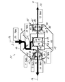
図1には、従来技術から一般的に公知のような、自動車のパワートレーンのための可変のトルク分配を有する伝動装置ユニット101を概略的に示した。伝動装置ユニット101は、図示していない多段伝動装置から推進軸102を介して駆動され、入力されたトルクは2つの車軸に分配される。伝動装置ユニットは、差動装置ケース107を有する差動伝動装置103を備えており、差動装置ケース107は、鉛直方向に設置された、つまり縦置きの差動装置ハウジング104内で回転軸線Bを中心に回転可能に支承されている。差動装置ケース107にリングギアとしての冠歯車117が取り付けられており、冠歯車117は、推進軸102と結合された傘歯車111に噛み合い、傘歯車111によって駆動される。差動装置ケース107内で、複数の差動歯車110が、回転軸線Bに対して直行するピン112に回動可能に支承されており、ピン112は差動装置ケース107と共に回転する。差動歯車110に2つのサイド歯車113,114が噛み合っており、サイド歯車113,114は、車軸にトルクを伝達するのに役立つ。
FIG. 1 schematically shows a transmission unit 101 with variable torque distribution for a motor vehicle power train, as is generally known from the prior art. The transmission unit 101 is driven from a multistage transmission (not shown) via the
差動伝動装置103に側方で隣接して、車軸174,175にトルクを可変に分配するための2つの伝動装置段125,125´が設けられている。これらの伝動装置段125,125´は同形に形成されているので、以下に一方について説明する。伝動装置段125は第1の太陽歯車126を備えており、第1の太陽歯車126は差動装置ケース107と相対回動不能に(つまり一緒に回転するように)結合されており、また伝動装置段125は、第1の太陽歯車126に噛み合う遊星歯車127と、遊星歯車127に噛み合う第2の太陽歯車128とを備えており、第2の太陽歯車128は車軸と相対回動不能に結合されている。遊星歯車127は、それぞれ2つの歯列区分129,130を備えており、歯列区分129,130のうちの一方は第1の太陽歯車126に噛み合い、また別の一方は第2の太陽歯車128に噛み合う。回転数変化を実現するために、両方の太陽歯車126,128はそれぞれ異なる歯数を有しており、また遊星歯車127の両方の歯列区分129,130はそれぞれ異なる歯数を有している。遊星歯車127はキャリア132に回動可能に収容されており、キャリア132は遊星歯車127と共に回転軸線Bを中心に回転することができる。キャリア132はクラッチ137によって差動装置ハウジング104に連結可能であり、これによって追加的なトルクを該当する車軸に伝達することができる。
Adjacent to the
以下に伝動装置ユニット101を通るトルク流れ経過の一例について説明する。図面から判るように、先ず100Nmのトルクが推進軸102から冠歯車117を介して差動装置ケース107に入力される。通常の走行条件、つまりキャリア132が自由に回転する状態では、入力されたトルクは、均等に両方のサイド歯車113,114に50:50の比で分配される。現行の走行力学状態によって、自動車の両輪のうちの一方に比較的大きなトルクを及ぼすよう要求されると、適当な伝動装置段125,125´がアクティブ化される。ここでは左側の車軸もしくは図示していない左側の車輪に比較的大きなトルクを伝達しようとする場合を示した。このために左側のクラッチ137が作動させられ、つまりこの時点まで自由に回転軸線を中心に回転していたキャリア132は、差動装置ハウジング104に対して制動される。したがって差動装置ケース107から、第1の太陽歯車126と遊星歯車127とを介して左側の車軸に伝達されるトルク成分が分岐される。この場合差動装置ケース107から分岐したトルク成分は10Nmであるので、差動歯車に90Nmのトルクが割り当てられる。差動歯車110を介して入力されたトルクは、均等に両方のサイド歯車113,114に分配され、つまり各車軸に45Nmのトルク成分が分配される。差動装置ケース107から追加的に分岐した10Nmのトルクは、左側の車軸に加えられる。この場合クラッチ137における熱損失によって約1Nmのトルクが失われるので、左側の車軸に追加的に9Nmのトルクが伝達され、左側の車軸に合計54Nmのトルクが導入される。総じてカーブ外側の左側の車輪とカーブ内側の右側の車輪との間で、54Nm:45Nmの比が生じる。
In the following, an example of the course of torque flow through the transmission unit 101 will be described. As can be seen from the drawing, a torque of 100 Nm is first input from the
図2には、部分的に図示した差動装置ハウジング4内に設けられた差動伝動装置3と本発明による2つの伝動装置モジュール5,6とを備えた伝動装置ユニット1を示した。伝動装置ユニット1の構造および機能形式は、本発明による伝動装置モジュール5,6を除いて、図1に示した伝動装置ユニットに実質的に相当するので、図1の説明が適用されるものとする。同じ構成部材には100を引いた符号を設けた。本発明による伝動装置モジュール5,6は、個別的な構成ユニットとして形成されていて、かつ両方の車軸にトルクを可変に分配するのに役立つ。右側の伝動装置モジュールの構成部材には、「´」を付けた符号を設けた。
FIG. 2 shows a
差動伝動装置3は、相対回動不能に冠歯車17の結合された差動装置ケース7を備えており、冠歯車17は、推進軸2と結合された傘歯車11に噛み合い、傘歯車11によって駆動される。推進軸2は、図示していない転がり軸受によって差動装置ハウジング4内で縦軸線Aを中心に回動可能に支承されている。差動装置ケース7は、スリーブ状の2つの付加部を備えており、付加部によって、差動装置ケース7は、転がり軸受8を用いて回転軸線Bを中心に回動可能に差動装置ハウジング4内で支承されている。差動装置ケース7内で、複数の差動歯車10が、回転軸線Bに直交するピン12に回動可能に支承されており、ピン12は差動装置ケース7と共に回転する。差動歯車10に2つのサイド歯車13,14が噛み合っており、サイド歯車13,14は伝動装置モジュール5,6もしくは該当する車軸にトルク伝達するのに役立つ。サイド歯車13,14は差動装置ケース7内で回転軸線Bを中心に回動可能に支承されており、この場合摩擦ディスク15,16が設けられており、これによって差動歯車10からサイド歯車13,14へのトルク伝達によって形成される軸方向の拡開力を差動装置ハウジング4に対して支持することができる。
The
両方の伝動装置モジュール5,6は、差動伝動装置3の、ピン軸線によって形成される中央平面に関して鏡面対称的に配置されている。両方の伝動装置モジュール5,6は、構造および機能形式に関して同一に形成されているので、以下に両方の伝動装置のうちの一方について説明する。これについては図3に詳しく示した。
Both
各モジュール5,6はハウジング18を備えており、ハウジング18内で第1の軸19が軸受20によって回動可能に支承されている。第1の軸19は、縦歯列を介して、差動伝動装置3の、該当するサイド歯車13,14と相対回動不能に結合されている。第1の軸19に、これと同軸的に第2の軸22が滑り軸受によって回動可能に支承されている。第2の軸22は、縦歯列を介して、差動装置ケース7と相対回動不能に結合されている。第1の軸19は、差動伝動装置3とは反対側の端部で、自動車の、図示していない該当する車軸と結合するためのフランジ21を備えている。第1の軸19は、ハウジング18に対して、転がり軸受20によって回動可能に支承されていて、かつ非接触式のシールキャップ23と接触式のシールリング24とによってシールされている。
Each of the
第1の軸19と第2の軸22とは、トルク伝達のための伝動装置段25を介して互いに結合されている。伝動装置段25は第1の太陽歯車26を備えており、第1の太陽歯車26は第2の軸22と一体的に結合されており、また伝動装置段25は、第1の太陽歯車26に噛み合う遊星歯車27と、遊星歯車27に噛み合う第2の太陽歯車28とを備えており、第2の太陽歯車28は、縦歯列を介して第1の軸19と相対回動不能に結合されている。遊星歯車27は、それぞれ一体的に形成されていて、かつ2つの歯列区分29,30を備えており、2つの歯列区分29,30のうちの一方は第1の太陽歯車26に噛み合い、別の一方は第2の太陽歯車28に噛み合う。歯列ははす歯歯列として形成されており、これによって有利ないわゆるNVH特性(ノイズ−バイブレーション−ハーシュネス)を得ることができる。この場合はす歯歯列は、トルク伝達時に太陽歯車26,28に作用する軸方向力が互いに向き合うように形成されている。両方の太陽歯車26,28の間にスラスト軸受31が設けられており、スラスト軸受31は、両方の太陽歯車26,28の相互的な軸方向の支持を保証する。スラスト軸受31と遊星歯車27との間に十分なスペースを提供するために、遊星歯車27は、スラスト軸受31を軸方向で重畳する領域に、環状に延びる溝33を備えている。比較的小さなスラスト軸受31を使用する場合、遊星歯車における溝は省略することもできる。第1の軸19と第2の軸22との間の回転数伝達比変化を達成するために、両方の太陽歯車26,28はそれぞれ異なる歯数を有している。この場合遊星歯車27の歯数および太陽歯車26,28の歯数は、第1の軸19と第2の軸22との間で20%までの回転数差が得られるように選択されている。
The
遊星歯車27は、ニードル軸受40によって共通のキャリア32内でピン39に回動可能に収容されており、キャリア32は、ケース状に形成されていて、かつ外側に向かって実質的に閉鎖されている。キャリア32は、金属薄板から成るポット状の2つの変形部57,58から製作されており、変形部57,58は、遊星歯車27および太陽歯車26,28の挿入後に互いに堅固に結合されていて、特に溶接されている。この場合キャリア32は、遊星歯車27、太陽歯車26,28および第2の軸22と共に前組立可能な構成群56を成し、構成群56は第1の軸19に被せ嵌められる。前組立可能な構成群56は図4に詳しく示した。図面から判るように、キャリア32は外周面34で係合手段35を備えており、係合手段35に、トルク伝達のためのクラッチ37のインナープレート36が係合できる。金属薄板から成るポット状の両方のキャリア部分57,58は、それぞれ軸方向の孔59を備えており、孔59に中空ピン39が差し込まれており、中空ピン39に、遊星歯車27がニードル軸受によって支承されている。さらに環状に延びる溶接シーム60が看取され、溶接シーム60は両方のキャリア部分57,58を互いに結合する。キャリア32に潤滑剤を導入するために、外周面34に半径方向の貫通孔62が設けられており、貫通孔62を通って潤滑剤はハウジング18の内室からキャリア32の内室に到達することができる。
The
クラッチ37は、キャリア32を遊星歯車27と共にハウジング18に連結するのに役立ち、これによって追加的なトルクを直接差動装置ケース7で分岐させ、第2の軸22と伝動装置段25とを介して第1の軸19に伝達することができる。クラッチ37は、多板クラッチとして形成されていて、かつインナープレート36の横に、これに対して交互に配置されたアウタープレート38を備えており、アウタープレート38はハウジング18に対して相対回動不能に保持されている。アウタープレート38とインナープレート36とから成る多板セットは、ハウジング18に対して軸方向で支持面41に支持されていて、かつ軸方向調節装置42によって作動させられる。
The clutch 37 serves to connect the
軸方向調節装置42は、ボールランプユニットとして形成されていて、かつ2つのディスク43,44を備えており、ディスク43,44は、相対回動可能であり、かつ周方向で深さ変化可能な、ボール47を収容するためのボール溝45,46を備えている。両方のディスクのうちの一方は支持ディスク43として形成されており、支持ディスク43はハウジング18に対して軸方向で支持されている。両方のディスクのうちの別の一方は調節ディスク44として形成されており、調節ディスク44は、支持ディスク43に対して回動可能であり、かつ軸方向可動であり、これによってスラスト軸受48および押圧板49を介して多板セットを軸方向力で負荷することができる。したがってクラッチ37が閉じられると、キャリア32はハウジング18に対して制動される。
The axial direction adjusting device 42 is formed as a ball ramp unit and includes two
ボールランプユニット42は、電動モータ52によってピニオン軸53を介して制御され、ピニオン軸53はハウジング18に回動可能に支承されている。ピニオン軸53は歯列54を備えており、歯列54は、調節ディスク44に設けられた対抗歯列55に噛み合う。電動モータ52は図示していない電子調整装置によって制御され、電子調整装置は自動車の走行力学を調整するのに役立つ。
The ball lamp unit 42 is controlled by an
図3から判るように、ハウジング18は、差動伝動装置3に向かって、フランジの構成をした接続手段62を備えており、接続手段62は開口61を包囲する。組立のために、図示した構成ユニットはフランジ62で、差動装置ハウジング4にねじ固定される。この場合第1の軸19は、差込結合部を介して、差動伝動装置3の、該当するサイド歯車13と相対回動不能に結合されている。第2の軸22も同様に、差込結合部を介して差動装置ケース7と相対回動不能に結合されている。差動伝動装置3および伝動装置モジュール5は、組立後に共通の内室を形成し、かつ共通の潤滑剤を使用する。
As can be seen from FIG. 3, the
図5には、本発明による伝動装置モジュール5´´の選択的な実施例を示した。伝動装置モジュール5´´は、図2および図3に示した伝動装置モジュール5に実質的に相当するものであり、ここでは図2および図3に関する記載が適用されるものとする。同一の構成部材には同一の符号を設け、変化した構成部材には「´´」を付した符号を設けた。ここで述べる伝動装置モジュール5´´の特徴によれば、ハウジング18´´がカバー63を備えており、カバー63は構成ユニットを外側に向かって閉鎖する。カバー63は、半径方向内側に、シールリング65を収容するための孔64を備えており、シールリング65は第2の軸22に緊密に支承されている。構成ユニット5´´は完全に差動伝動装置3から独立しており、差動伝動装置3に構成ユニット5´´は接続することができる。このような構成の利点によれば、伝動装置モジュール5´´の冷却および潤滑のために、差動伝動装置3のための潤滑剤とは別の潤滑剤を使用することができる。
FIG. 5 shows an alternative embodiment of the
図6には、前述の伝動装置モジュールに類似した、本発明による別の伝動装置モジュール5´´´の実施例を示した。伝動装置モジュール5´´´は、図2および図3もしくは図5に示した伝動装置モジュールに実質的に相当するものであり、ここでも前述の記載が適用されるものとする。同一の構成部材には同一の符号を設け、変化した構成部材には「´´´」を付した記号を設けた。図6に示した伝動装置モジュール5´´´の特徴によれば、カバー63と第2の軸22との間のシール手段が省略される。したがって伝動装置モジュール5´´´と差動伝動装置3とのために同じ潤滑剤を使用することができ、潤滑剤はリングギャップ64を通過することができる。同時にカバー63によって、個々の構成部材が取扱時にハウジング18´´から落下しないよう確保される。
FIG. 6 shows an embodiment of another
以下に本発明による伝動装置モジュールのための様々な使用例について説明する。 In the following, various examples of use for the transmission module according to the invention will be described.
図7には、駆動される前車軸(フロントアクスル)66と従動する後車軸(リアアクスル)67とを備えた自動車のパワートレーンを示した。ここでは後車軸67において走行輪68,69だけを図示し、懸架部は図示していない。前車軸66を駆動するために、伝動装置ユニット71を備えた、自動車長手方向に設置された、つまり縦置きのエンジン70が設けられている。伝動装置ユニット71は、変速機72と、トルクを両方の車軸74,75に分配するための軸差動装置73とを備えている。軸差動装置73(図2に示した実施例と同一であり、その説明が適用されるものとする)において、各車軸74,75に、本発明による、前方の駆動輪76,77にトルクを可変に分配するための伝動装置モジュール5,6が接続されている。したがって軸差動装置73に導入されるトルクは、必要に応じて、両方の車軸74,75もしくは両方の走行輪76,77に分配され、これによって最適な走行安定性が得られる。特にカーブ走行時にカーブ外側の駆動輪に追加的なトルクを及ぼすことができる。
FIG. 7 shows a power train of an automobile provided with a driven front axle (front axle) 66 and a driven rear axle (rear axle) 67. Here, only the traveling
図8には、図7に類似の実施例を示した。ここでは図7の説明が適用されるものとする。唯一の相違点によれば、エンジン70´は、ここでは縦置きではなく横置きで組み付けられている。
FIG. 8 shows an embodiment similar to FIG. Here, the description of FIG. 7 is applied. The only difference is that the
図9には、駆動される後車軸67´と従動する前車軸66´とを備えた自動車のパワートレーンを示しており、ここでは図7に示した構成部材とは異なる構成部材には、「´」を付した符号を設けた。ここでは前車軸66´において、単に走行輪76,77を図示し、懸架部は図示していない。エンジン−伝動装置−ユニット70´,71´によって、推進軸78を介して、後車軸67´の軸差動装置83が駆動される。軸差動装置83(図2に示した実施例と同一であり、その説明が適用されるものとする)において、各車軸79,80に、本発明による、後方の駆動輪68,69にトルクを可変に分配するための伝動装置モジュール5,6が接続される。したがって軸差動装置83に導入されるトルクは、必要に応じて、両方の車軸79,80もしくは両方の駆動輪68,69に分配され、これによって最適な走行安定性が得られる。特にカーブ走行時にカーブ外側の駆動輪に追加的なトルクを及ぼすことができる。
FIG. 9 shows a power train of an automobile having a
図10には、駆動される前車軸66´´と駆動される後車軸67´´とを備えた自動車のパワートレーンを示した。ここでは変化した構成部材には「´´」を付した符号を設けた。前車軸66´´には、軸差動装置73、2つの車軸74,75ならびに駆動される駆動輪76,77が看取される。後車軸67´´には、軸差動装置83、2つの車軸79,80ならびに駆動される駆動輪68,69が看取される。エンジン−伝動装置−ユニット70´´,71´´は、一定のトルク分配を有する分配伝動装置71´´を備えており、分配伝動装置71´´の出力軸は、一方では前方の推進軸81を介して前車軸66´´の軸差動装置73を駆動し、また他方では後方の推進軸78を介して後車軸67´´の軸差動装置83を駆動する。分配伝動装置71´´には中央差動装置93が組み込まれており、中央差動装置93は、その都度のスリップに応じて、前車軸66´´と後車軸67´´との間の駆動モーメントの適合を行う。中央差動装置93(図2に示した実施例に類似しており、その説明が適用されるものとする)に、本発明による、前車軸66´´と後車軸67´´との間のトルクを可変に分配するための伝動装置モジュール5が接続される。したがって特定の走行状況で後車軸67´´に比較的高いトルクを及ぼすことができ、これによって最適な走行安定性が得られる。
FIG. 10 shows a power train of an automobile having a
図11には、駆動される前車軸66´´と駆動される後車軸67´´とを備えた自動車のパワートレーンを示した。図11に示したパワートレーンは、図10に示したパワートレーンに実質的に相当するものであり、その説明が適用されるものとする。同一の構成部材には同一の符号を設けた。図9に示した実施例との相違点によれば、中央差動装置93に対して追加的に本発明による伝動装置モジュール5,6が軸差動装置73,83に接続されている。したがって前車軸66´´の両方の車軸74,75に及ぼされる可変のトルク分配と、後車軸67´´の両方の車軸79,80に及ぼされる可変のトルク分配とが保証される。後方の軸差動装置83に接続された本発明による伝動装置モジュール5,6については、図9に示したパワートレーンの説明を参照されたい。前方の軸差動装置73に接続された本発明による伝動装置モジュール5,6については、図7に示したパワートレーンの説明を参照されたい。この実施例によって最大限の走行安定性が保証される。なぜならば前車軸66´´と後車軸67´´との間のトルク分配も、各車軸74,75,79,80に及ぼされる前車軸66´´の内側および後車軸67´´の内側のトルク分配も可変に分配可能である、という理由による。
FIG. 11 shows a power train of an automobile having a
1 伝動装置ユニット、 2 推進軸、 3 差動伝動装置、 4 差動装置ハウジング、 5 第1の伝動装置モジュール、 6 第2の伝動装置モジュール、 7 差動装置ケース、 8,9 転がり軸受、 10 差動歯車、 11 傘歯車、 12 ピン、 13,14 サイド歯車、 15,16 摩擦ディスク、 17 冠歯車、 18 ハウジング、 19 第1の軸、 20 転がり軸受、 21 フランジ、 22 第2の軸、 23 シールキャップ、 24 シール、 25 伝動装置段、 26 第1の太陽歯車、 27 遊星歯車、 28 第2の太陽歯車、 29,30 歯列区分、 31 スラスト軸受、 32 キャリア、 33 溝、 34 外周面、 35 係合手段、 36 インナープレート、 37 クラッチ、 38 アウタープレート、 39 ピン、 40 ニードル軸受、 41 支持面、 42 軸方向調節装置、 43 第1のディスク、支持ディスク、 44 第2のディスク、調節ディスク、 45,46 ボール溝、 47 ボール、 48 スラスト軸受、 49 押圧板、 51 縦歯列、 52 電動モータ、 53 ピニオン軸、 54 歯列、 55 対抗歯列、 56 構成群、 57,58 キャリア部、 59 孔、 60 溶接シーム、 61 縦歯列、 62 貫通孔、 63 カバー、 64 孔、リングギャップ、 65 シール、 66 前車軸、 67 後車軸、 68,69 走行輪、 70 エンジン、 71 伝動装置ユニット、 72 変速機、 73 軸差動装置、 74,75 車軸、 76,77 走行輪、 78 推進軸、 79,80 車軸、 81 推進軸、 83 軸差動装置、 93 中央差動装置 DESCRIPTION OF SYMBOLS 1 Transmission unit, 2 Propulsion shaft, 3 Differential transmission, 4 Differential housing, 5 1st transmission module, 6 2nd transmission module, 7 Differential case, 8, 9 Rolling bearing, 10 Differential gear, 11 Bevel gear, 12 Pin, 13, 14 Side gear, 15, 16 Friction disk, 17 Crown gear, 18 Housing, 19 First shaft, 20 Rolling bearing, 21 Flange, 22 Second shaft, 23 Seal cap, 24 seal, 25 transmission stage, 26 first sun gear, 27 planetary gear, 28 second sun gear, 29, 30 dentition section, 31 thrust bearing, 32 carrier, 33 groove, 34 outer peripheral surface, 35 engaging means, 36 inner plate, 37 clutch, 38 outer plate, 3 9 pin, 40 needle bearing, 41 support surface, 42 axial adjustment device, 43 first disc, support disc, 44 second disc, adjustment disc, 45, 46 ball groove, 47 ball, 48 thrust bearing, 49 press Plate, 51 Vertical tooth row, 52 Electric motor, 53 Pinion shaft, 54 Teeth row, 55 Counter tooth row, 56 Component group, 57, 58 Carrier part, 59 holes, 60 Weld seam, 61 Vertical tooth row, 62 Through hole, 63 cover, 64 hole, ring gap, 65 seal, 66 front axle, 67 rear axle, 68, 69 traveling wheel, 70 engine, 71 transmission unit, 72 transmission, 73 shaft differential, 74,75 axle, 76 , 77 traveling wheel, 78 propulsion shaft, 79,80 axle, 81 propulsion shaft, 83 Axial differential, 93 Central differential
Claims (5)
第1の軸(19)が設けられており、該第1の軸(19)が、回転軸線(B)を中心に縦置きのハウジング(18)に対して回動可能に支承されており、
該第1の軸(19)に対して同軸的に配置された第2の軸(22)が設けられており、該第2の軸(22)が、第1の軸(19)と駆動結合されており、
少なくとも1つの遊星歯車(27)と、少なくとも1つの遊星歯車(27)を支持するキャリア(32)とを備えた、第1の軸(19)と第2の軸(22)との間のトルク流れ経路に配置された伝動装置段(25)が設けられており、キャリア(32)が、回転軸線(B)を中心に回転可能に形成されており、
クラッチ(37)が設けられており、該クラッチ(37)が、ハウジング(18)に支持されていて、かつハウジング(18)に対してキャリア(32)を連結するのに役立ち、
ハウジング(18)に対してキャリア(32)を連結することによって、第1および第2の軸(19,22)のうちの一方から、第1および第2の軸(19,22)のうちの別の一方へのトルク伝達が行われるようになっており、
ハウジング(18)、第1の軸(19)、第2の軸(22)、伝動装置段(25)およびクラッチ(37)が、1構成ユニットの一部を成しており、
ハウジング(18)に接続手段(62)が設けられており、該接続手段(62)を介して構成ユニットが伝動装置(3)に接続されるようになっており、
少なくとも1つの遊星歯車(27)の第1の歯列区分と第2の歯列区分(29,30)とが、同形に形成されており、第1の太陽歯車と第2の太陽歯車(26,28)とが、それぞれ異なる歯数を有していることを特徴とする、可変のトルク分配のための伝動装置モジュール。 In the transmission module (5, 6) for variable torque distribution in the vehicle powertrain,
A first shaft (19) is provided, and the first shaft (19) is supported so as to be rotatable with respect to the vertical housing (18) about the rotation axis (B).
A second shaft (22) is provided coaxially with respect to the first shaft (19), and the second shaft (22) is drivingly coupled to the first shaft (19). Has been
Torque between the first shaft (19) and the second shaft (22) with at least one planetary gear (27) and a carrier (32) supporting the at least one planetary gear (27) A transmission stage (25) disposed in the flow path is provided, and the carrier (32) is formed to be rotatable about the rotation axis (B);
A clutch (37) is provided, which is supported on the housing (18) and serves to connect the carrier (32) to the housing (18);
By connecting the carrier (32) to the housing (18), from one of the first and second shafts (19, 22), one of the first and second shafts (19, 22). Torque is transmitted to the other side,
The housing (18), the first shaft (19), the second shaft (22), the transmission stage (25) and the clutch (37) form part of one component unit,
The housing (18) is provided with connection means (62), and the component unit is connected to the transmission (3) via the connection means (62) .
The first tooth section and the second tooth section (29, 30) of the at least one planetary gear (27) are formed in the same shape, and the first sun gear and the second sun gear (26 , 28) have a different number of teeth, respectively, and a transmission module for variable torque distribution.
前輪または後輪の左右2つの車軸(74,75;79,80)を備えた1つの被駆動軸(66,67)と、左右2つの車軸(74,75;79,80)にトルクを可変に分配するための軸差動装置(73,83)とが設けられており、
軸差動装置(73,83)が、縦置きの差動装置ハウジング(4)内で回動可能に支承された差動装置ケース(7)と、差動装置ケース(7)内で回動可能に支承された2つのサイド歯車(13,14)と、両方のサイド歯車(13,14)に噛み合う複数の差動歯車(10)とを備えており、
請求項1に記載の第1の伝動装置モジュール(5)が設けられており、第1の伝動装置モジュール(5)のハウジング(18)が、接続手段(62)を介して、縦置きの差動装置ハウジング(4)と堅固に結合されており、第1の伝動装置モジュール(5)の第1の軸(19)が、両方のサイド歯車(13,14)のうちの一方と相対回動不能に結合されており、第1の伝動装置モジュール(5)の第2の軸(22)が、差動装置ケース(7)と相対回動不能に結合されており、
請求項1記載の第2の伝動装置モジュール(6)が設けられており、第2の伝動装置モジュール(6)のハウジング(18´)が、接続手段(62´)を介して、縦置きの差動装置ハウジング(4)と堅固に結合されており、第2の伝動装置モジュール(6)の第1の軸(19´)が、両方のサイド歯車(13,14)のうちの別の一方と相対回動不能に結合されており、第2の伝動装置モジュール(6)の第2の軸(22´)が、差動装置ケース(7)と相対回動不能に結合されていることを特徴とする、自動車。 In cars,
Two right and left axles of the front wheels or the rear wheels; one driven shaft provided with a (74, 75 79, 80) and (66, 67), two left and right axles; the torque (74, 75 79, 80) Shaft differentials (73, 83) for variable distribution are provided,
A shaft differential device (73, 83) is rotatably supported in a vertically installed differential device housing (4) and is rotated in the differential device case (7). Two side gears (13, 14) supported in a possible manner and a plurality of differential gears (10) meshing with both side gears (13, 14),
A first transmission device module (5) according to claim 1 is provided, the housing (18) of the first transmission device module (5) being connected vertically via a connection means (62). Firmly connected to the gear housing (4), the first shaft (19) of the first gear module (5) pivots relative to one of the side gears (13, 14). The second shaft (22) of the first transmission module (5) is coupled to the differential case (7) so as not to be rotatable relative to the first transmission module (5);
A second transmission device module (6) according to claim 1 is provided, the housing (18 ') of the second transmission device module (6) being placed vertically via the connection means (62'). Firmly connected to the differential housing (4), the first shaft (19 ') of the second transmission module (6) is connected to the other one of the side gears (13, 14) The second shaft (22 ') of the second transmission module ( 6 ) is coupled to the differential case (7) so as not to rotate relative to the differential gear case (7). Characteristic car.
前後の2つの被駆動軸(66,67)と、前後の2つの被駆動軸(66,67)にトルクを可変に分割するための中央差動装置(93)が設けられており、
中央差動装置(93)が、縦置きの差動装置ハウジング内で回動可能に支承された差動装置ケースと、差動装置ケース内で回動可能に支承された2つのサイド歯車と、サイド歯車に噛み合う複数の差動歯車とを備えており、
中央差動装置(93)に、請求項1記載の伝動装置モジュール(5)が設けられており、伝動装置モジュール(5)のハウジング(18)が、接続手段(62)を介して、縦置きの差動装置ハウジングと堅固に結合されており、伝動装置モジュール(5)の第1の軸(19)が、両方のサイド歯車のうちの一方と相対回動不能に結合されており、伝動装置モジュール(5)の第2の軸(22)が、差動装置ケースと相対回動不能に結合されていることを特徴とする、自動車。 In cars,
Two driven shafts of the front and rear and (66, 67), and a central differential for dividing variably the two torque to the driven shaft (66, 67) before and after (93) is provided,
A central differential (93) having a differential case rotatably supported in a longitudinal differential housing, and two side gears rotatably supported in the differential case; A plurality of differential gears meshing with the side gears,
The central differential (93) is provided with the transmission module (5) according to claim 1, wherein the housing (18) of the transmission module (5) is placed vertically via the connection means (62). And the first shaft (19) of the transmission module (5) is non-rotatably coupled with one of both side gears, A motor vehicle characterized in that the second shaft (22) of the module (5) is connected to the differential case in a non-rotatable manner.
Applications Claiming Priority (2)
| Application Number | Priority Date | Filing Date | Title |
|---|---|---|---|
| DE102005004290.2 | 2005-01-28 | ||
| DE102005004290A DE102005004290B4 (en) | 2005-01-28 | 2005-01-28 | Transmission module for variable torque distribution |
Publications (3)
| Publication Number | Publication Date |
|---|---|
| JP2006207804A JP2006207804A (en) | 2006-08-10 |
| JP2006207804A5 JP2006207804A5 (en) | 2009-01-22 |
| JP4960627B2 true JP4960627B2 (en) | 2012-06-27 |
Family
ID=36709494
Family Applications (1)
| Application Number | Title | Priority Date | Filing Date |
|---|---|---|---|
| JP2005362147A Active JP4960627B2 (en) | 2005-01-28 | 2005-12-15 | Transmission module for variable torque distribution and motor vehicle equipped with the transmission module |
Country Status (4)
| Country | Link |
|---|---|
| US (1) | US7442143B2 (en) |
| JP (1) | JP4960627B2 (en) |
| AT (1) | AT503359B1 (en) |
| DE (1) | DE102005004290B4 (en) |
Families Citing this family (24)
| Publication number | Priority date | Publication date | Assignee | Title |
|---|---|---|---|---|
| DE102005004291B4 (en) * | 2005-01-28 | 2007-05-31 | Gkn Driveline International Gmbh | Gear arrangement for variable torque distribution |
| DE102005051501B3 (en) * | 2005-10-26 | 2007-07-05 | Gkn Driveline International Gmbh | Arrangement for torque detection on a friction clutch |
| DE102005051500B3 (en) * | 2005-10-26 | 2007-07-05 | Gkn Driveline International Gmbh | Determining torque acting on multi-plate friction clutch in vehicle, includes force measurement system within clutch casing, acted upon by plate carrier stud when clutch is operated |
| DE102005053555B3 (en) * | 2005-11-08 | 2007-08-02 | Gkn Driveline International Gmbh | Ball ramp arrangement with variable pitch of the ball grooves |
| DE602005024321D1 (en) * | 2005-12-02 | 2010-12-02 | Haldex Traction Ab | METHOD AND SYSTEM FOR DRIVING DYNAMIC CONTROL |
| DE102005061268B4 (en) * | 2005-12-20 | 2007-09-27 | Gkn Driveline International Gmbh | Friction clutch with actuator and disc spring |
| US7491147B2 (en) * | 2006-05-03 | 2009-02-17 | Gm Global Technology Operations, Inc. | Torque vectoring differential apparatus |
| DE102006025072A1 (en) * | 2006-05-30 | 2007-12-06 | Zf Friedrichshafen Ag | Transmission unit for guiding a drive torque from a drive shaft to two output shafts |
| DE102006025062A1 (en) * | 2006-05-30 | 2007-12-06 | Zf Friedrichshafen Ag | Gear unit for guiding a drive torque from a drive shaft to two drive shafts |
| DE102006025058A1 (en) * | 2006-05-30 | 2007-12-06 | Zf Friedrichshafen Ag | Gear unit for guiding a drive torque from a drive shaft to two drive shafts |
| DE102006025071A1 (en) * | 2006-05-30 | 2007-12-06 | Zf Friedrichshafen Ag | Gear unit for guiding a drive torque from a drive shaft to two output shafts |
| US7704178B2 (en) | 2006-07-05 | 2010-04-27 | United Technologies Corporation | Oil baffle for gas turbine fan drive gear system |
| US8667688B2 (en) | 2006-07-05 | 2014-03-11 | United Technologies Corporation | Method of assembly for gas turbine fan drive gear system |
| DE102007010982B4 (en) | 2007-03-05 | 2008-11-20 | Gkn Driveline International Gmbh | Transmission module for variable torque distribution |
| DE102007011895B4 (en) | 2007-03-13 | 2018-04-26 | Schaeffler Technologies AG & Co. KG | Spurraddzialzial and overlay differential with the spur gear differential |
| WO2008137883A1 (en) * | 2007-05-04 | 2008-11-13 | Entropy Solutions, Inc. | Package having phase change materials and method of use in transport of temperature sensitive payload |
| DE102007022182B4 (en) | 2007-05-11 | 2015-08-06 | Zf Friedrichshafen Ag | Transmission device for distributing a drive torque to at least two output shafts |
| US8617024B2 (en) * | 2009-07-31 | 2013-12-31 | Deere & Company | Axle final drive assembly |
| US9731598B2 (en) | 2010-07-23 | 2017-08-15 | Fca Us Llc | Multi-mode drive system for transaxle applications |
| DE102015103584A1 (en) | 2015-03-11 | 2016-09-15 | Gkn Driveline International Gmbh | Gear arrangement and electric drive with such a gear arrangement |
| DE102015112102A1 (en) | 2015-07-24 | 2017-01-26 | Gkn Driveline International Gmbh | Coupling module for a drive train and drive arrangement with a coupling module |
| CN109562682B (en) | 2016-06-03 | 2020-03-10 | Gkn汽车有限公司 | Electric drive arrangement and drive train having an electric drive arrangement of this type |
| US10724445B2 (en) | 2018-01-03 | 2020-07-28 | Raytheon Technologies Corporation | Method of assembly for fan drive gear system with rotating carrier |
| CN112682492B (en) * | 2021-02-04 | 2023-03-31 | 象山申达轿车配件有限公司 | Differential gear |
Family Cites Families (9)
| Publication number | Priority date | Publication date | Assignee | Title |
|---|---|---|---|---|
| JPH083735Y2 (en) * | 1989-08-04 | 1996-01-31 | 本田技研工業株式会社 | Differential device with differential limiting mechanism |
| US5692987A (en) * | 1994-07-05 | 1997-12-02 | Honda Giken Kogyo Kabushiki Kaisha | Power transmitting system for vehicle |
| JPH10166884A (en) * | 1996-12-04 | 1998-06-23 | Fuji Heavy Ind Ltd | Vehicular right and left driving force distributing device |
| JP3103779B2 (en) | 1996-11-22 | 2000-10-30 | 建治 三村 | Differential device |
| JP4116146B2 (en) * | 1998-05-06 | 2008-07-09 | Gkn ドライブライン トルクテクノロジー株式会社 | Differential device |
| US6571928B1 (en) * | 2001-12-21 | 2003-06-03 | Gkn Automotive, Inc. | Engagement mechanism with two stage ramp angle |
| US6752233B1 (en) * | 2003-02-11 | 2004-06-22 | General Motors Corporation | Selectable overspeed secondary drive module |
| US6802794B2 (en) * | 2003-02-21 | 2004-10-12 | Borgwarner, Inc. | Single actuator lost motion shift assembly |
| DE10342164B4 (en) * | 2003-09-12 | 2005-10-20 | Gkn Driveline Int Gmbh | transmission assembly |
-
2005
- 2005-01-28 DE DE102005004290A patent/DE102005004290B4/en active Active
- 2005-11-16 AT AT0187005A patent/AT503359B1/en active
- 2005-12-15 JP JP2005362147A patent/JP4960627B2/en active Active
- 2005-12-27 US US11/318,655 patent/US7442143B2/en active Active
Also Published As
| Publication number | Publication date |
|---|---|
| AT503359B1 (en) | 2009-06-15 |
| AT503359A3 (en) | 2009-04-15 |
| AT503359A2 (en) | 2007-09-15 |
| US20060172845A1 (en) | 2006-08-03 |
| DE102005004290A1 (en) | 2006-08-10 |
| US7442143B2 (en) | 2008-10-28 |
| JP2006207804A (en) | 2006-08-10 |
| DE102005004290B4 (en) | 2006-11-02 |
Similar Documents
| Publication | Publication Date | Title |
|---|---|---|
| JP4960627B2 (en) | Transmission module for variable torque distribution and motor vehicle equipped with the transmission module | |
| JP2006207805A (en) | Transmission device unit for variable torque distribution | |
| CN108374846B (en) | Clutch assembly for a drive train and drive assembly having such a clutch assembly | |
| KR101229321B1 (en) | Differential transmission unit featuring active controlling of the moment distribution | |
| JP4313828B2 (en) | Left / right driving force distribution device | |
| US8056442B2 (en) | All-wheel drivetrain for a motor vehicle | |
| CN104670011B (en) | Have the torque-transmitting mechanisms of Packed ball ramp clutch operating device unit | |
| JP5096370B2 (en) | Transmission assembly for variable torque distribution | |
| JP5135226B2 (en) | Differential device having two axial adjustment devices operated together | |
| JP2006175951A5 (en) | ||
| JP2015507160A (en) | Pure electric driveable car drivetrain | |
| WO2009100187A2 (en) | Continuously variable torque vectoring axle assembly | |
| JP2008208990A (en) | Drive assembly equipped with intermediate shaft and clutch unit | |
| JP2004249979A (en) | Transfer case equipped with two planetary gears having common carrier | |
| US8939862B2 (en) | Final drive mechanism and power take off for a transmission | |
| US11524574B2 (en) | Axle drive | |
| JP5477471B2 (en) | Vehicle drive device | |
| JP2007505276A (en) | Transmission assembly | |
| US7819771B2 (en) | Asymmetrical, active axle transmission | |
| KR100876481B1 (en) | Multi-speed automatic transmission with three planetary gearsets | |
| JP2004114193A (en) | Method for assembling power transmission | |
| JP5171699B2 (en) | Final reduction gear for vehicle | |
| JP4895053B2 (en) | Left / right driving force distribution device | |
| JP2024515326A (en) | Fluid guide assembly for a friction multiplate clutch and clutch unit equipped with the fluid guide assembly | |
| JPH07259956A (en) | Differential gear |
Legal Events
| Date | Code | Title | Description |
|---|---|---|---|
| A521 | Request for written amendment filed |
Free format text: JAPANESE INTERMEDIATE CODE: A523 Effective date: 20081128 |
|
| A621 | Written request for application examination |
Free format text: JAPANESE INTERMEDIATE CODE: A621 Effective date: 20081128 |
|
| RD04 | Notification of resignation of power of attorney |
Free format text: JAPANESE INTERMEDIATE CODE: A7424 Effective date: 20101228 |
|
| A977 | Report on retrieval |
Free format text: JAPANESE INTERMEDIATE CODE: A971007 Effective date: 20110418 |
|
| A131 | Notification of reasons for refusal |
Free format text: JAPANESE INTERMEDIATE CODE: A131 Effective date: 20110421 |
|
| A601 | Written request for extension of time |
Free format text: JAPANESE INTERMEDIATE CODE: A601 Effective date: 20110721 |
|
| A602 | Written permission of extension of time |
Free format text: JAPANESE INTERMEDIATE CODE: A602 Effective date: 20110726 |
|
| A601 | Written request for extension of time |
Free format text: JAPANESE INTERMEDIATE CODE: A601 Effective date: 20110822 |
|
| A602 | Written permission of extension of time |
Free format text: JAPANESE INTERMEDIATE CODE: A602 Effective date: 20110825 |
|
| A521 | Request for written amendment filed |
Free format text: JAPANESE INTERMEDIATE CODE: A523 Effective date: 20110913 |
|
| TRDD | Decision of grant or rejection written | ||
| A01 | Written decision to grant a patent or to grant a registration (utility model) |
Free format text: JAPANESE INTERMEDIATE CODE: A01 Effective date: 20120314 |
|
| A01 | Written decision to grant a patent or to grant a registration (utility model) |
Free format text: JAPANESE INTERMEDIATE CODE: A01 |
|
| A61 | First payment of annual fees (during grant procedure) |
Free format text: JAPANESE INTERMEDIATE CODE: A61 Effective date: 20120323 |
|
| FPAY | Renewal fee payment (event date is renewal date of database) |
Free format text: PAYMENT UNTIL: 20150330 Year of fee payment: 3 |
|
| R150 | Certificate of patent or registration of utility model |
Free format text: JAPANESE INTERMEDIATE CODE: R150 Ref document number: 4960627 Country of ref document: JP Free format text: JAPANESE INTERMEDIATE CODE: R150 |
|
| R250 | Receipt of annual fees |
Free format text: JAPANESE INTERMEDIATE CODE: R250 |
|
| R250 | Receipt of annual fees |
Free format text: JAPANESE INTERMEDIATE CODE: R250 |
|
| R250 | Receipt of annual fees |
Free format text: JAPANESE INTERMEDIATE CODE: R250 |
|
| R250 | Receipt of annual fees |
Free format text: JAPANESE INTERMEDIATE CODE: R250 |
|
| R250 | Receipt of annual fees |
Free format text: JAPANESE INTERMEDIATE CODE: R250 |
|
| R250 | Receipt of annual fees |
Free format text: JAPANESE INTERMEDIATE CODE: R250 |
|
| S111 | Request for change of ownership or part of ownership |
Free format text: JAPANESE INTERMEDIATE CODE: R313113 |
|
| R350 | Written notification of registration of transfer |
Free format text: JAPANESE INTERMEDIATE CODE: R350 |
|
| R250 | Receipt of annual fees |
Free format text: JAPANESE INTERMEDIATE CODE: R250 |
|
| R250 | Receipt of annual fees |
Free format text: JAPANESE INTERMEDIATE CODE: R250 |
|
| R250 | Receipt of annual fees |
Free format text: JAPANESE INTERMEDIATE CODE: R250 |
|
| R250 | Receipt of annual fees |
Free format text: JAPANESE INTERMEDIATE CODE: R250 |