JP4960318B2 - Method and apparatus for minimizing misalignments appearing on the surface of composite parts - Google Patents
Method and apparatus for minimizing misalignments appearing on the surface of composite parts Download PDFInfo
- Publication number
- JP4960318B2 JP4960318B2 JP2008198002A JP2008198002A JP4960318B2 JP 4960318 B2 JP4960318 B2 JP 4960318B2 JP 2008198002 A JP2008198002 A JP 2008198002A JP 2008198002 A JP2008198002 A JP 2008198002A JP 4960318 B2 JP4960318 B2 JP 4960318B2
- Authority
- JP
- Japan
- Prior art keywords
- composite
- strip
- layer
- cured
- composite strip
- Prior art date
- Legal status (The legal status is an assumption and is not a legal conclusion. Google has not performed a legal analysis and makes no representation as to the accuracy of the status listed.)
- Active
Links
- 239000002131 composite material Substances 0.000 title claims description 318
- 238000000034 method Methods 0.000 title claims description 59
- 239000010410 layer Substances 0.000 claims description 129
- 210000000569 greater omentum Anatomy 0.000 claims description 52
- 239000004744 fabric Substances 0.000 claims description 27
- 230000008569 process Effects 0.000 claims description 22
- 239000000835 fiber Substances 0.000 claims description 20
- 229920005989 resin Polymers 0.000 claims description 17
- 239000011347 resin Substances 0.000 claims description 17
- 239000012790 adhesive layer Substances 0.000 claims description 7
- 238000004519 manufacturing process Methods 0.000 description 16
- 239000000463 material Substances 0.000 description 15
- 230000008439 repair process Effects 0.000 description 7
- 229920001187 thermosetting polymer Polymers 0.000 description 6
- 239000002313 adhesive film Substances 0.000 description 5
- 238000002360 preparation method Methods 0.000 description 5
- 230000005012 migration Effects 0.000 description 4
- 238000013508 migration Methods 0.000 description 4
- 239000004634 thermosetting polymer Substances 0.000 description 3
- 239000004593 Epoxy Substances 0.000 description 2
- 239000000853 adhesive Substances 0.000 description 2
- 230000006835 compression Effects 0.000 description 2
- 238000007906 compression Methods 0.000 description 2
- 238000013461 design Methods 0.000 description 2
- 239000000945 filler Substances 0.000 description 2
- 238000010438 heat treatment Methods 0.000 description 2
- 238000005304 joining Methods 0.000 description 2
- 238000012423 maintenance Methods 0.000 description 2
- 238000012986 modification Methods 0.000 description 2
- 230000004048 modification Effects 0.000 description 2
- 238000000465 moulding Methods 0.000 description 2
- 229920000728 polyester Polymers 0.000 description 2
- 239000003381 stabilizer Substances 0.000 description 2
- ZOXJGFHDIHLPTG-UHFFFAOYSA-N Boron Chemical compound [B] ZOXJGFHDIHLPTG-UHFFFAOYSA-N 0.000 description 1
- OKTJSMMVPCPJKN-UHFFFAOYSA-N Carbon Chemical compound [C] OKTJSMMVPCPJKN-UHFFFAOYSA-N 0.000 description 1
- 229920000049 Carbon (fiber) Polymers 0.000 description 1
- 239000004677 Nylon Substances 0.000 description 1
- 239000004696 Poly ether ether ketone Substances 0.000 description 1
- 239000004695 Polyether sulfone Substances 0.000 description 1
- 229920001807 Urea-formaldehyde Polymers 0.000 description 1
- 230000001070 adhesive effect Effects 0.000 description 1
- 230000002411 adverse Effects 0.000 description 1
- 229920000180 alkyd Polymers 0.000 description 1
- 239000004760 aramid Substances 0.000 description 1
- 229920003235 aromatic polyamide Polymers 0.000 description 1
- 229910052796 boron Inorganic materials 0.000 description 1
- 229910052799 carbon Inorganic materials 0.000 description 1
- 239000004917 carbon fiber Substances 0.000 description 1
- 239000000919 ceramic Substances 0.000 description 1
- 230000003247 decreasing effect Effects 0.000 description 1
- 230000007547 defect Effects 0.000 description 1
- 238000010586 diagram Methods 0.000 description 1
- 238000010894 electron beam technology Methods 0.000 description 1
- 230000007613 environmental effect Effects 0.000 description 1
- 125000003700 epoxy group Chemical group 0.000 description 1
- 239000011152 fibreglass Substances 0.000 description 1
- 239000000446 fuel Substances 0.000 description 1
- 238000002347 injection Methods 0.000 description 1
- 239000007924 injection Substances 0.000 description 1
- 230000010354 integration Effects 0.000 description 1
- 238000010030 laminating Methods 0.000 description 1
- 239000003562 lightweight material Substances 0.000 description 1
- 239000004973 liquid crystal related substance Substances 0.000 description 1
- 230000007246 mechanism Effects 0.000 description 1
- 239000007769 metal material Substances 0.000 description 1
- VNWKTOKETHGBQD-UHFFFAOYSA-N methane Chemical compound C VNWKTOKETHGBQD-UHFFFAOYSA-N 0.000 description 1
- 239000000203 mixture Substances 0.000 description 1
- 229920001778 nylon Polymers 0.000 description 1
- 238000010422 painting Methods 0.000 description 1
- 230000000737 periodic effect Effects 0.000 description 1
- 229920000647 polyepoxide Polymers 0.000 description 1
- 229920006393 polyether sulfone Polymers 0.000 description 1
- 229920002530 polyetherether ketone Polymers 0.000 description 1
- ODGAOXROABLFNM-UHFFFAOYSA-N polynoxylin Chemical compound O=C.NC(N)=O ODGAOXROABLFNM-UHFFFAOYSA-N 0.000 description 1
- -1 polytetrafluoroethylene Polymers 0.000 description 1
- 239000004810 polytetrafluoroethylene Substances 0.000 description 1
- 229920001343 polytetrafluoroethylene Polymers 0.000 description 1
- 238000009419 refurbishment Methods 0.000 description 1
- 239000000758 substrate Substances 0.000 description 1
- 230000007704 transition Effects 0.000 description 1
- 230000000007 visual effect Effects 0.000 description 1
- 239000013585 weight reducing agent Substances 0.000 description 1
Images


Classifications
-
- B—PERFORMING OPERATIONS; TRANSPORTING
- B29—WORKING OF PLASTICS; WORKING OF SUBSTANCES IN A PLASTIC STATE IN GENERAL
- B29C—SHAPING OR JOINING OF PLASTICS; SHAPING OF MATERIAL IN A PLASTIC STATE, NOT OTHERWISE PROVIDED FOR; AFTER-TREATMENT OF THE SHAPED PRODUCTS, e.g. REPAIRING
- B29C70/00—Shaping composites, i.e. plastics material comprising reinforcements, fillers or preformed parts, e.g. inserts
- B29C70/04—Shaping composites, i.e. plastics material comprising reinforcements, fillers or preformed parts, e.g. inserts comprising reinforcements only, e.g. self-reinforcing plastics
- B29C70/28—Shaping operations therefor
- B29C70/30—Shaping by lay-up, i.e. applying fibres, tape or broadsheet on a mould, former or core; Shaping by spray-up, i.e. spraying of fibres on a mould, former or core
- B29C70/34—Shaping by lay-up, i.e. applying fibres, tape or broadsheet on a mould, former or core; Shaping by spray-up, i.e. spraying of fibres on a mould, former or core and shaping or impregnating by compression, i.e. combined with compressing after the lay-up operation
- B29C70/342—Shaping by lay-up, i.e. applying fibres, tape or broadsheet on a mould, former or core; Shaping by spray-up, i.e. spraying of fibres on a mould, former or core and shaping or impregnating by compression, i.e. combined with compressing after the lay-up operation using isostatic pressure
-
- B—PERFORMING OPERATIONS; TRANSPORTING
- B29—WORKING OF PLASTICS; WORKING OF SUBSTANCES IN A PLASTIC STATE IN GENERAL
- B29C—SHAPING OR JOINING OF PLASTICS; SHAPING OF MATERIAL IN A PLASTIC STATE, NOT OTHERWISE PROVIDED FOR; AFTER-TREATMENT OF THE SHAPED PRODUCTS, e.g. REPAIRING
- B29C66/00—General aspects of processes or apparatus for joining preformed parts
- B29C66/50—General aspects of joining tubular articles; General aspects of joining long products, i.e. bars or profiled elements; General aspects of joining single elements to tubular articles, hollow articles or bars; General aspects of joining several hollow-preforms to form hollow or tubular articles
- B29C66/51—Joining tubular articles, profiled elements or bars; Joining single elements to tubular articles, hollow articles or bars; Joining several hollow-preforms to form hollow or tubular articles
- B29C66/53—Joining single elements to tubular articles, hollow articles or bars
- B29C66/532—Joining single elements to the wall of tubular articles, hollow articles or bars
-
- B—PERFORMING OPERATIONS; TRANSPORTING
- B29—WORKING OF PLASTICS; WORKING OF SUBSTANCES IN A PLASTIC STATE IN GENERAL
- B29C—SHAPING OR JOINING OF PLASTICS; SHAPING OF MATERIAL IN A PLASTIC STATE, NOT OTHERWISE PROVIDED FOR; AFTER-TREATMENT OF THE SHAPED PRODUCTS, e.g. REPAIRING
- B29C70/00—Shaping composites, i.e. plastics material comprising reinforcements, fillers or preformed parts, e.g. inserts
- B29C70/04—Shaping composites, i.e. plastics material comprising reinforcements, fillers or preformed parts, e.g. inserts comprising reinforcements only, e.g. self-reinforcing plastics
- B29C70/28—Shaping operations therefor
- B29C70/40—Shaping or impregnating by compression not applied
- B29C70/42—Shaping or impregnating by compression not applied for producing articles of definite length, i.e. discrete articles
- B29C70/44—Shaping or impregnating by compression not applied for producing articles of definite length, i.e. discrete articles using isostatic pressure, e.g. pressure difference-moulding, vacuum bag-moulding, autoclave-moulding or expanding rubber-moulding
- B29C70/446—Moulding structures having an axis of symmetry or at least one channel, e.g. tubular structures, frames
-
- B—PERFORMING OPERATIONS; TRANSPORTING
- B29—WORKING OF PLASTICS; WORKING OF SUBSTANCES IN A PLASTIC STATE IN GENERAL
- B29C—SHAPING OR JOINING OF PLASTICS; SHAPING OF MATERIAL IN A PLASTIC STATE, NOT OTHERWISE PROVIDED FOR; AFTER-TREATMENT OF THE SHAPED PRODUCTS, e.g. REPAIRING
- B29C70/00—Shaping composites, i.e. plastics material comprising reinforcements, fillers or preformed parts, e.g. inserts
- B29C70/04—Shaping composites, i.e. plastics material comprising reinforcements, fillers or preformed parts, e.g. inserts comprising reinforcements only, e.g. self-reinforcing plastics
- B29C70/28—Shaping operations therefor
- B29C70/54—Component parts, details or accessories; Auxiliary operations, e.g. feeding or storage of prepregs or SMC after impregnation or during ageing
- B29C70/549—Details of caul plates, e.g. materials or shape
-
- B—PERFORMING OPERATIONS; TRANSPORTING
- B29—WORKING OF PLASTICS; WORKING OF SUBSTANCES IN A PLASTIC STATE IN GENERAL
- B29C—SHAPING OR JOINING OF PLASTICS; SHAPING OF MATERIAL IN A PLASTIC STATE, NOT OTHERWISE PROVIDED FOR; AFTER-TREATMENT OF THE SHAPED PRODUCTS, e.g. REPAIRING
- B29C70/00—Shaping composites, i.e. plastics material comprising reinforcements, fillers or preformed parts, e.g. inserts
- B29C70/68—Shaping composites, i.e. plastics material comprising reinforcements, fillers or preformed parts, e.g. inserts by incorporating or moulding on preformed parts, e.g. inserts or layers, e.g. foam blocks
-
- B—PERFORMING OPERATIONS; TRANSPORTING
- B29—WORKING OF PLASTICS; WORKING OF SUBSTANCES IN A PLASTIC STATE IN GENERAL
- B29C—SHAPING OR JOINING OF PLASTICS; SHAPING OF MATERIAL IN A PLASTIC STATE, NOT OTHERWISE PROVIDED FOR; AFTER-TREATMENT OF THE SHAPED PRODUCTS, e.g. REPAIRING
- B29C37/00—Component parts, details, accessories or auxiliary operations, not covered by group B29C33/00 or B29C35/00
- B29C37/02—Deburring or deflashing
-
- B—PERFORMING OPERATIONS; TRANSPORTING
- B29—WORKING OF PLASTICS; WORKING OF SUBSTANCES IN A PLASTIC STATE IN GENERAL
- B29C—SHAPING OR JOINING OF PLASTICS; SHAPING OF MATERIAL IN A PLASTIC STATE, NOT OTHERWISE PROVIDED FOR; AFTER-TREATMENT OF THE SHAPED PRODUCTS, e.g. REPAIRING
- B29C39/00—Shaping by casting, i.e. introducing the moulding material into a mould or between confining surfaces without significant moulding pressure; Apparatus therefor
-
- B—PERFORMING OPERATIONS; TRANSPORTING
- B29—WORKING OF PLASTICS; WORKING OF SUBSTANCES IN A PLASTIC STATE IN GENERAL
- B29C—SHAPING OR JOINING OF PLASTICS; SHAPING OF MATERIAL IN A PLASTIC STATE, NOT OTHERWISE PROVIDED FOR; AFTER-TREATMENT OF THE SHAPED PRODUCTS, e.g. REPAIRING
- B29C65/00—Joining or sealing of preformed parts, e.g. welding of plastics materials; Apparatus therefor
- B29C65/02—Joining or sealing of preformed parts, e.g. welding of plastics materials; Apparatus therefor by heating, with or without pressure
-
- B—PERFORMING OPERATIONS; TRANSPORTING
- B29—WORKING OF PLASTICS; WORKING OF SUBSTANCES IN A PLASTIC STATE IN GENERAL
- B29C—SHAPING OR JOINING OF PLASTICS; SHAPING OF MATERIAL IN A PLASTIC STATE, NOT OTHERWISE PROVIDED FOR; AFTER-TREATMENT OF THE SHAPED PRODUCTS, e.g. REPAIRING
- B29C65/00—Joining or sealing of preformed parts, e.g. welding of plastics materials; Apparatus therefor
- B29C65/48—Joining or sealing of preformed parts, e.g. welding of plastics materials; Apparatus therefor using adhesives, i.e. using supplementary joining material; solvent bonding
- B29C65/50—Joining or sealing of preformed parts, e.g. welding of plastics materials; Apparatus therefor using adhesives, i.e. using supplementary joining material; solvent bonding using adhesive tape, e.g. thermoplastic tape; using threads or the like
- B29C65/5057—Joining or sealing of preformed parts, e.g. welding of plastics materials; Apparatus therefor using adhesives, i.e. using supplementary joining material; solvent bonding using adhesive tape, e.g. thermoplastic tape; using threads or the like positioned between the surfaces to be joined
-
- B—PERFORMING OPERATIONS; TRANSPORTING
- B29—WORKING OF PLASTICS; WORKING OF SUBSTANCES IN A PLASTIC STATE IN GENERAL
- B29C—SHAPING OR JOINING OF PLASTICS; SHAPING OF MATERIAL IN A PLASTIC STATE, NOT OTHERWISE PROVIDED FOR; AFTER-TREATMENT OF THE SHAPED PRODUCTS, e.g. REPAIRING
- B29C66/00—General aspects of processes or apparatus for joining preformed parts
- B29C66/01—General aspects dealing with the joint area or with the area to be joined
- B29C66/05—Particular design of joint configurations
- B29C66/10—Particular design of joint configurations particular design of the joint cross-sections
- B29C66/11—Joint cross-sections comprising a single joint-segment, i.e. one of the parts to be joined comprising a single joint-segment in the joint cross-section
- B29C66/112—Single lapped joints
- B29C66/1122—Single lap to lap joints, i.e. overlap joints
-
- B—PERFORMING OPERATIONS; TRANSPORTING
- B29—WORKING OF PLASTICS; WORKING OF SUBSTANCES IN A PLASTIC STATE IN GENERAL
- B29C—SHAPING OR JOINING OF PLASTICS; SHAPING OF MATERIAL IN A PLASTIC STATE, NOT OTHERWISE PROVIDED FOR; AFTER-TREATMENT OF THE SHAPED PRODUCTS, e.g. REPAIRING
- B29C66/00—General aspects of processes or apparatus for joining preformed parts
- B29C66/50—General aspects of joining tubular articles; General aspects of joining long products, i.e. bars or profiled elements; General aspects of joining single elements to tubular articles, hollow articles or bars; General aspects of joining several hollow-preforms to form hollow or tubular articles
- B29C66/51—Joining tubular articles, profiled elements or bars; Joining single elements to tubular articles, hollow articles or bars; Joining several hollow-preforms to form hollow or tubular articles
- B29C66/52—Joining tubular articles, bars or profiled elements
- B29C66/522—Joining tubular articles
-
- B—PERFORMING OPERATIONS; TRANSPORTING
- B29—WORKING OF PLASTICS; WORKING OF SUBSTANCES IN A PLASTIC STATE IN GENERAL
- B29C—SHAPING OR JOINING OF PLASTICS; SHAPING OF MATERIAL IN A PLASTIC STATE, NOT OTHERWISE PROVIDED FOR; AFTER-TREATMENT OF THE SHAPED PRODUCTS, e.g. REPAIRING
- B29C66/00—General aspects of processes or apparatus for joining preformed parts
- B29C66/50—General aspects of joining tubular articles; General aspects of joining long products, i.e. bars or profiled elements; General aspects of joining single elements to tubular articles, hollow articles or bars; General aspects of joining several hollow-preforms to form hollow or tubular articles
- B29C66/51—Joining tubular articles, profiled elements or bars; Joining single elements to tubular articles, hollow articles or bars; Joining several hollow-preforms to form hollow or tubular articles
- B29C66/53—Joining single elements to tubular articles, hollow articles or bars
- B29C66/532—Joining single elements to the wall of tubular articles, hollow articles or bars
- B29C66/5326—Joining single elements to the wall of tubular articles, hollow articles or bars said single elements being substantially flat
-
- B—PERFORMING OPERATIONS; TRANSPORTING
- B29—WORKING OF PLASTICS; WORKING OF SUBSTANCES IN A PLASTIC STATE IN GENERAL
- B29C—SHAPING OR JOINING OF PLASTICS; SHAPING OF MATERIAL IN A PLASTIC STATE, NOT OTHERWISE PROVIDED FOR; AFTER-TREATMENT OF THE SHAPED PRODUCTS, e.g. REPAIRING
- B29C66/00—General aspects of processes or apparatus for joining preformed parts
- B29C66/70—General aspects of processes or apparatus for joining preformed parts characterised by the composition, physical properties or the structure of the material of the parts to be joined; Joining with non-plastics material
- B29C66/71—General aspects of processes or apparatus for joining preformed parts characterised by the composition, physical properties or the structure of the material of the parts to be joined; Joining with non-plastics material characterised by the composition of the plastics material of the parts to be joined
-
- B—PERFORMING OPERATIONS; TRANSPORTING
- B29—WORKING OF PLASTICS; WORKING OF SUBSTANCES IN A PLASTIC STATE IN GENERAL
- B29C—SHAPING OR JOINING OF PLASTICS; SHAPING OF MATERIAL IN A PLASTIC STATE, NOT OTHERWISE PROVIDED FOR; AFTER-TREATMENT OF THE SHAPED PRODUCTS, e.g. REPAIRING
- B29C66/00—General aspects of processes or apparatus for joining preformed parts
- B29C66/70—General aspects of processes or apparatus for joining preformed parts characterised by the composition, physical properties or the structure of the material of the parts to be joined; Joining with non-plastics material
- B29C66/72—General aspects of processes or apparatus for joining preformed parts characterised by the composition, physical properties or the structure of the material of the parts to be joined; Joining with non-plastics material characterised by the structure of the material of the parts to be joined
- B29C66/721—Fibre-reinforced materials
- B29C66/7212—Fibre-reinforced materials characterised by the composition of the fibres
-
- B—PERFORMING OPERATIONS; TRANSPORTING
- B29—WORKING OF PLASTICS; WORKING OF SUBSTANCES IN A PLASTIC STATE IN GENERAL
- B29C—SHAPING OR JOINING OF PLASTICS; SHAPING OF MATERIAL IN A PLASTIC STATE, NOT OTHERWISE PROVIDED FOR; AFTER-TREATMENT OF THE SHAPED PRODUCTS, e.g. REPAIRING
- B29C66/00—General aspects of processes or apparatus for joining preformed parts
- B29C66/70—General aspects of processes or apparatus for joining preformed parts characterised by the composition, physical properties or the structure of the material of the parts to be joined; Joining with non-plastics material
- B29C66/72—General aspects of processes or apparatus for joining preformed parts characterised by the composition, physical properties or the structure of the material of the parts to be joined; Joining with non-plastics material characterised by the structure of the material of the parts to be joined
- B29C66/721—Fibre-reinforced materials
- B29C66/7214—Fibre-reinforced materials characterised by the length of the fibres
- B29C66/72141—Fibres of continuous length
-
- B—PERFORMING OPERATIONS; TRANSPORTING
- B29—WORKING OF PLASTICS; WORKING OF SUBSTANCES IN A PLASTIC STATE IN GENERAL
- B29C—SHAPING OR JOINING OF PLASTICS; SHAPING OF MATERIAL IN A PLASTIC STATE, NOT OTHERWISE PROVIDED FOR; AFTER-TREATMENT OF THE SHAPED PRODUCTS, e.g. REPAIRING
- B29C66/00—General aspects of processes or apparatus for joining preformed parts
- B29C66/70—General aspects of processes or apparatus for joining preformed parts characterised by the composition, physical properties or the structure of the material of the parts to be joined; Joining with non-plastics material
- B29C66/72—General aspects of processes or apparatus for joining preformed parts characterised by the composition, physical properties or the structure of the material of the parts to be joined; Joining with non-plastics material characterised by the structure of the material of the parts to be joined
- B29C66/723—General aspects of processes or apparatus for joining preformed parts characterised by the composition, physical properties or the structure of the material of the parts to be joined; Joining with non-plastics material characterised by the structure of the material of the parts to be joined being multi-layered
-
- B—PERFORMING OPERATIONS; TRANSPORTING
- B29—WORKING OF PLASTICS; WORKING OF SUBSTANCES IN A PLASTIC STATE IN GENERAL
- B29C—SHAPING OR JOINING OF PLASTICS; SHAPING OF MATERIAL IN A PLASTIC STATE, NOT OTHERWISE PROVIDED FOR; AFTER-TREATMENT OF THE SHAPED PRODUCTS, e.g. REPAIRING
- B29C66/00—General aspects of processes or apparatus for joining preformed parts
- B29C66/70—General aspects of processes or apparatus for joining preformed parts characterised by the composition, physical properties or the structure of the material of the parts to be joined; Joining with non-plastics material
- B29C66/73—General aspects of processes or apparatus for joining preformed parts characterised by the composition, physical properties or the structure of the material of the parts to be joined; Joining with non-plastics material characterised by the intensive physical properties of the material of the parts to be joined, by the optical properties of the material of the parts to be joined, by the extensive physical properties of the parts to be joined, by the state of the material of the parts to be joined or by the material of the parts to be joined being a thermoplastic or a thermoset
- B29C66/737—General aspects of processes or apparatus for joining preformed parts characterised by the composition, physical properties or the structure of the material of the parts to be joined; Joining with non-plastics material characterised by the intensive physical properties of the material of the parts to be joined, by the optical properties of the material of the parts to be joined, by the extensive physical properties of the parts to be joined, by the state of the material of the parts to be joined or by the material of the parts to be joined being a thermoplastic or a thermoset characterised by the state of the material of the parts to be joined
- B29C66/7375—General aspects of processes or apparatus for joining preformed parts characterised by the composition, physical properties or the structure of the material of the parts to be joined; Joining with non-plastics material characterised by the intensive physical properties of the material of the parts to be joined, by the optical properties of the material of the parts to be joined, by the extensive physical properties of the parts to be joined, by the state of the material of the parts to be joined or by the material of the parts to be joined being a thermoplastic or a thermoset characterised by the state of the material of the parts to be joined uncured, partially cured or fully cured
- B29C66/73751—General aspects of processes or apparatus for joining preformed parts characterised by the composition, physical properties or the structure of the material of the parts to be joined; Joining with non-plastics material characterised by the intensive physical properties of the material of the parts to be joined, by the optical properties of the material of the parts to be joined, by the extensive physical properties of the parts to be joined, by the state of the material of the parts to be joined or by the material of the parts to be joined being a thermoplastic or a thermoset characterised by the state of the material of the parts to be joined uncured, partially cured or fully cured the to-be-joined area of at least one of the parts to be joined being uncured, i.e. non cross-linked, non vulcanized
-
- B—PERFORMING OPERATIONS; TRANSPORTING
- B29—WORKING OF PLASTICS; WORKING OF SUBSTANCES IN A PLASTIC STATE IN GENERAL
- B29C—SHAPING OR JOINING OF PLASTICS; SHAPING OF MATERIAL IN A PLASTIC STATE, NOT OTHERWISE PROVIDED FOR; AFTER-TREATMENT OF THE SHAPED PRODUCTS, e.g. REPAIRING
- B29C66/00—General aspects of processes or apparatus for joining preformed parts
- B29C66/70—General aspects of processes or apparatus for joining preformed parts characterised by the composition, physical properties or the structure of the material of the parts to be joined; Joining with non-plastics material
- B29C66/73—General aspects of processes or apparatus for joining preformed parts characterised by the composition, physical properties or the structure of the material of the parts to be joined; Joining with non-plastics material characterised by the intensive physical properties of the material of the parts to be joined, by the optical properties of the material of the parts to be joined, by the extensive physical properties of the parts to be joined, by the state of the material of the parts to be joined or by the material of the parts to be joined being a thermoplastic or a thermoset
- B29C66/737—General aspects of processes or apparatus for joining preformed parts characterised by the composition, physical properties or the structure of the material of the parts to be joined; Joining with non-plastics material characterised by the intensive physical properties of the material of the parts to be joined, by the optical properties of the material of the parts to be joined, by the extensive physical properties of the parts to be joined, by the state of the material of the parts to be joined or by the material of the parts to be joined being a thermoplastic or a thermoset characterised by the state of the material of the parts to be joined
- B29C66/7375—General aspects of processes or apparatus for joining preformed parts characterised by the composition, physical properties or the structure of the material of the parts to be joined; Joining with non-plastics material characterised by the intensive physical properties of the material of the parts to be joined, by the optical properties of the material of the parts to be joined, by the extensive physical properties of the parts to be joined, by the state of the material of the parts to be joined or by the material of the parts to be joined being a thermoplastic or a thermoset characterised by the state of the material of the parts to be joined uncured, partially cured or fully cured
- B29C66/73753—General aspects of processes or apparatus for joining preformed parts characterised by the composition, physical properties or the structure of the material of the parts to be joined; Joining with non-plastics material characterised by the intensive physical properties of the material of the parts to be joined, by the optical properties of the material of the parts to be joined, by the extensive physical properties of the parts to be joined, by the state of the material of the parts to be joined or by the material of the parts to be joined being a thermoplastic or a thermoset characterised by the state of the material of the parts to be joined uncured, partially cured or fully cured the to-be-joined area of at least one of the parts to be joined being partially cured, i.e. partially cross-linked, partially vulcanized
-
- B—PERFORMING OPERATIONS; TRANSPORTING
- B29—WORKING OF PLASTICS; WORKING OF SUBSTANCES IN A PLASTIC STATE IN GENERAL
- B29C—SHAPING OR JOINING OF PLASTICS; SHAPING OF MATERIAL IN A PLASTIC STATE, NOT OTHERWISE PROVIDED FOR; AFTER-TREATMENT OF THE SHAPED PRODUCTS, e.g. REPAIRING
- B29C66/00—General aspects of processes or apparatus for joining preformed parts
- B29C66/70—General aspects of processes or apparatus for joining preformed parts characterised by the composition, physical properties or the structure of the material of the parts to be joined; Joining with non-plastics material
- B29C66/73—General aspects of processes or apparatus for joining preformed parts characterised by the composition, physical properties or the structure of the material of the parts to be joined; Joining with non-plastics material characterised by the intensive physical properties of the material of the parts to be joined, by the optical properties of the material of the parts to be joined, by the extensive physical properties of the parts to be joined, by the state of the material of the parts to be joined or by the material of the parts to be joined being a thermoplastic or a thermoset
- B29C66/739—General aspects of processes or apparatus for joining preformed parts characterised by the composition, physical properties or the structure of the material of the parts to be joined; Joining with non-plastics material characterised by the intensive physical properties of the material of the parts to be joined, by the optical properties of the material of the parts to be joined, by the extensive physical properties of the parts to be joined, by the state of the material of the parts to be joined or by the material of the parts to be joined being a thermoplastic or a thermoset characterised by the material of the parts to be joined being a thermoplastic or a thermoset
- B29C66/7394—General aspects of processes or apparatus for joining preformed parts characterised by the composition, physical properties or the structure of the material of the parts to be joined; Joining with non-plastics material characterised by the intensive physical properties of the material of the parts to be joined, by the optical properties of the material of the parts to be joined, by the extensive physical properties of the parts to be joined, by the state of the material of the parts to be joined or by the material of the parts to be joined being a thermoplastic or a thermoset characterised by the material of the parts to be joined being a thermoplastic or a thermoset characterised by the material of at least one of the parts being a thermoset
- B29C66/73941—General aspects of processes or apparatus for joining preformed parts characterised by the composition, physical properties or the structure of the material of the parts to be joined; Joining with non-plastics material characterised by the intensive physical properties of the material of the parts to be joined, by the optical properties of the material of the parts to be joined, by the extensive physical properties of the parts to be joined, by the state of the material of the parts to be joined or by the material of the parts to be joined being a thermoplastic or a thermoset characterised by the material of the parts to be joined being a thermoplastic or a thermoset characterised by the material of at least one of the parts being a thermoset characterised by the materials of both parts being thermosets
-
- B—PERFORMING OPERATIONS; TRANSPORTING
- B29—WORKING OF PLASTICS; WORKING OF SUBSTANCES IN A PLASTIC STATE IN GENERAL
- B29L—INDEXING SCHEME ASSOCIATED WITH SUBCLASS B29C, RELATING TO PARTICULAR ARTICLES
- B29L2031/00—Other particular articles
- B29L2031/30—Vehicles, e.g. ships or aircraft, or body parts thereof
- B29L2031/3076—Aircrafts
- B29L2031/3082—Fuselages
-
- B—PERFORMING OPERATIONS; TRANSPORTING
- B32—LAYERED PRODUCTS
- B32B—LAYERED PRODUCTS, i.e. PRODUCTS BUILT-UP OF STRATA OF FLAT OR NON-FLAT, e.g. CELLULAR OR HONEYCOMB, FORM
- B32B17/00—Layered products essentially comprising sheet glass, or glass, slag, or like fibres
- B32B17/02—Layered products essentially comprising sheet glass, or glass, slag, or like fibres in the form of fibres or filaments
- B32B17/04—Layered products essentially comprising sheet glass, or glass, slag, or like fibres in the form of fibres or filaments bonded with or embedded in a plastic substance
-
- B—PERFORMING OPERATIONS; TRANSPORTING
- B32—LAYERED PRODUCTS
- B32B—LAYERED PRODUCTS, i.e. PRODUCTS BUILT-UP OF STRATA OF FLAT OR NON-FLAT, e.g. CELLULAR OR HONEYCOMB, FORM
- B32B19/00—Layered products comprising a layer of natural mineral fibres or particles, e.g. asbestos, mica
- B32B19/04—Layered products comprising a layer of natural mineral fibres or particles, e.g. asbestos, mica next to another layer of the same or of a different material
-
- B—PERFORMING OPERATIONS; TRANSPORTING
- B32—LAYERED PRODUCTS
- B32B—LAYERED PRODUCTS, i.e. PRODUCTS BUILT-UP OF STRATA OF FLAT OR NON-FLAT, e.g. CELLULAR OR HONEYCOMB, FORM
- B32B37/00—Methods or apparatus for laminating, e.g. by curing or by ultrasonic bonding
- B32B37/12—Methods or apparatus for laminating, e.g. by curing or by ultrasonic bonding characterised by using adhesives
- B32B2037/1253—Methods or apparatus for laminating, e.g. by curing or by ultrasonic bonding characterised by using adhesives curable adhesive
-
- B—PERFORMING OPERATIONS; TRANSPORTING
- B32—LAYERED PRODUCTS
- B32B—LAYERED PRODUCTS, i.e. PRODUCTS BUILT-UP OF STRATA OF FLAT OR NON-FLAT, e.g. CELLULAR OR HONEYCOMB, FORM
- B32B2305/00—Condition, form or state of the layers or laminate
- B32B2305/07—Parts immersed or impregnated in a matrix
- B32B2305/076—Prepregs
-
- B—PERFORMING OPERATIONS; TRANSPORTING
- B32—LAYERED PRODUCTS
- B32B—LAYERED PRODUCTS, i.e. PRODUCTS BUILT-UP OF STRATA OF FLAT OR NON-FLAT, e.g. CELLULAR OR HONEYCOMB, FORM
- B32B2309/00—Parameters for the laminating or treatment process; Apparatus details
- B32B2309/08—Dimensions, e.g. volume
- B32B2309/10—Dimensions, e.g. volume linear, e.g. length, distance, width
-
- B—PERFORMING OPERATIONS; TRANSPORTING
- B32—LAYERED PRODUCTS
- B32B—LAYERED PRODUCTS, i.e. PRODUCTS BUILT-UP OF STRATA OF FLAT OR NON-FLAT, e.g. CELLULAR OR HONEYCOMB, FORM
- B32B37/00—Methods or apparatus for laminating, e.g. by curing or by ultrasonic bonding
-
- B—PERFORMING OPERATIONS; TRANSPORTING
- B32—LAYERED PRODUCTS
- B32B—LAYERED PRODUCTS, i.e. PRODUCTS BUILT-UP OF STRATA OF FLAT OR NON-FLAT, e.g. CELLULAR OR HONEYCOMB, FORM
- B32B37/00—Methods or apparatus for laminating, e.g. by curing or by ultrasonic bonding
- B32B37/02—Methods or apparatus for laminating, e.g. by curing or by ultrasonic bonding characterised by a sequence of laminating steps, e.g. by adding new layers at consecutive laminating stations
-
- Y—GENERAL TAGGING OF NEW TECHNOLOGICAL DEVELOPMENTS; GENERAL TAGGING OF CROSS-SECTIONAL TECHNOLOGIES SPANNING OVER SEVERAL SECTIONS OF THE IPC; TECHNICAL SUBJECTS COVERED BY FORMER USPC CROSS-REFERENCE ART COLLECTIONS [XRACs] AND DIGESTS
- Y10—TECHNICAL SUBJECTS COVERED BY FORMER USPC
- Y10T—TECHNICAL SUBJECTS COVERED BY FORMER US CLASSIFICATION
- Y10T156/00—Adhesive bonding and miscellaneous chemical manufacture
- Y10T156/10—Methods of surface bonding and/or assembly therefor
- Y10T156/1089—Methods of surface bonding and/or assembly therefor of discrete laminae to single face of additional lamina
- Y10T156/1092—All laminae planar and face to face
- Y10T156/1093—All laminae planar and face to face with covering of discrete laminae with additional lamina
-
- Y—GENERAL TAGGING OF NEW TECHNOLOGICAL DEVELOPMENTS; GENERAL TAGGING OF CROSS-SECTIONAL TECHNOLOGIES SPANNING OVER SEVERAL SECTIONS OF THE IPC; TECHNICAL SUBJECTS COVERED BY FORMER USPC CROSS-REFERENCE ART COLLECTIONS [XRACs] AND DIGESTS
- Y10—TECHNICAL SUBJECTS COVERED BY FORMER USPC
- Y10T—TECHNICAL SUBJECTS COVERED BY FORMER US CLASSIFICATION
- Y10T428/00—Stock material or miscellaneous articles
- Y10T428/24—Structurally defined web or sheet [e.g., overall dimension, etc.]
- Y10T428/24752—Laterally noncoextensive components
- Y10T428/2476—Fabric, cloth or textile component
Landscapes
- Engineering & Computer Science (AREA)
- Mechanical Engineering (AREA)
- Chemical & Material Sciences (AREA)
- Composite Materials (AREA)
- Moulding By Coating Moulds (AREA)
- Lining Or Joining Of Plastics Or The Like (AREA)
- Casting Or Compression Moulding Of Plastics Or The Like (AREA)
- Laminated Bodies (AREA)
Description
本開示は概して複合材部品に関し、特に、複合材部品を製造するための方法および装置に関する。さらに詳細には、本開示は複合材部品の外観を改良するための方法および装置に関する。 The present disclosure relates generally to composite parts, and more particularly to methods and apparatus for manufacturing composite parts. More particularly, the present disclosure relates to a method and apparatus for improving the appearance of composite parts.
航空機の設計および製造に占める複合材料の割合がますます増大しつつある。主要な構造の50%以上が複合材料からなる航空機もある。複合材料を航空機に使用して、航空機を軽量化することができる。この軽量化によって、収益荷重容量および燃費が向上し得る。さらに、複合材料によって、航空機のさまざまな部品の耐用年数を延ばし得る。 The proportion of composite materials in aircraft design and manufacture is increasing. Some aircraft have more than 50% of their primary structure made of composite materials. Composite materials can be used in aircraft to reduce the weight of the aircraft. This weight reduction can improve profitable load capacity and fuel consumption. In addition, composite materials can extend the useful life of various aircraft components.
複合材料は堅い軽量材料であり、2つ以上の異質な部品を組合せることによって作製し得る。たとえば、複合材は繊維および樹脂を含み得る。繊維および樹脂を組合せて、硬化複合材料を形成し得る。 A composite material is a rigid, lightweight material that can be made by combining two or more dissimilar parts. For example, the composite can include fibers and resins. Fibers and resins can be combined to form a cured composite.
さらに、複合材料を用いることによって、航空機の部分をより大きなピースまたはセクションに作製し得る。たとえば、航空機の胴体は、組み立てると航空機の胴体を構成し得る円筒形のセクションに形成することができる。他の例には、限定はしないが、翼を形成するために接合される翼セクション、または安定板を形成するために接合される安定板セクションが含まれ得る。 Furthermore, by using composite materials, aircraft parts can be made into larger pieces or sections. For example, the aircraft fuselage can be formed into a cylindrical section that can be assembled to form the aircraft fuselage. Other examples may include, but are not limited to, a wing section joined to form a wing, or a stabilizer section joined to form a stabilizer.
複合材料または構造を湾曲もしくは環状の形状に作製するにあたって、複合材部品の内側モールドライン(IML)に対向して配置し得るモールドを用いて、複合材料を成形および/または積層し得る。その結果、複合材部品の内側モールドラインに接触する内側モールドを用いて、異なる特徴、テクスチャもしくは外観を、複合材部品および/または複合積層材の内面上に作製し得る。航空機の胴体の形態の複合材部品では、これらの特徴、テクスチャ、または外観を客室内部において使用し得る。これらの特徴、テクスチャ、または外観は、たとえば限定はしないが、窓、美観のために窓を囲む目に見えるライン、および客室壁上のテクスチャを含む。 In making the composite material or structure into a curved or annular shape, the composite material may be molded and / or laminated using a mold that may be placed against the inner mold line (IML) of the composite part. As a result, different features, textures or appearances can be created on the inner surface of the composite part and / or composite laminate using an inner mold that contacts the inner mold line of the composite part. For composite parts in the form of an aircraft fuselage, these features, textures, or appearances may be used inside the cabin. These features, textures, or appearances include, for example, without limitation, windows, visible lines surrounding the window for aesthetic purposes, and textures on the cabin walls.
複合材料で複合材部品を形成する際、複合材料からなる外側面または外側モールドライン(OML)は、内側モールドを使用する場合は、外側モールドに制約されない。胴体のセクションの場合は、この外側モールドラインが胴体および/または胴セクションの表面の外観を生じさせ得る。この種の複合材部品では、滑らかな表面が望まれる。 When forming a composite part with a composite material, the outer surface or outer mold line (OML) made of the composite material is not constrained to the outer mold when using an inner mold. In the case of a fuselage section, this outer mold line can give the appearance of the fuselage and / or the surface of the fuselage section. In this type of composite part, a smooth surface is desired.
部品の寸法によっては、複合材部品の硬化または形成中に、複数の当て板を複合材部品の外側面上に配置する必要があり得る。当て板は薄ゲージシートであり、限定はしないが、金属または複合材料で形成され得る。これらの当て板は、外側モールドラインを制御し、滑らかな表面を作成するために使用し得る。大きな複合材部品は、複数の当て板を必要とし得る。複数の当て板が使用される場合、これらの板は互いに隣り合って配置させ得る。複合材部品の製造中の硬化および/または加熱処理による当て板の熱膨張に対応するために、隣接する当て板同士の間に隙間を残し得る。 Depending on the dimensions of the part, it may be necessary to place a plurality of backing plates on the outer surface of the composite part during curing or forming of the composite part. The caul plate is a thin gauge sheet and can be formed of, but not limited to, a metal or composite material. These caul plates can be used to control the outer mold line and create a smooth surface. Large composite parts may require multiple patch plates. If a plurality of backing plates are used, these plates can be placed next to each other. To accommodate the thermal expansion of the caul plates due to curing and / or heat treatment during manufacture of the composite part, a gap may be left between adjacent caul plates.
当て板のエッジにおいては、視認できる型あと、繊維のうねり、および/または繊維の歪みなどの不整合が生じ得る。この型あとおよび繊維の歪みは、視認できるラインまたはシームとなり得る。当て板同士の間の隙間に露出した複合材料に真空バッグが接触した場合、および/または硬化処理中に当て板が重なった場合にも、この種の不整合が生じ得る
。さらに、容認し難い型あとまたは他の種類の不整合が硬化した複合材上に視認でき、かつ硬化中に当て板が存在していた隙間に位置している状態では、繊維のうねりが生じるおそれがある。これらの種類の不整合は望ましくない。
At the edge of the caul plate, misalignments such as visible mold, fiber undulation, and / or fiber distortion can occur. This post mold and fiber distortion can result in visible lines or seams. This type of misalignment can also occur when the vacuum bag comes into contact with the composite material exposed in the gap between the backing plates and / or when the backing plates overlap during the curing process. In addition, unacceptable molds or other types of misalignments are visible on the cured composite and may cause swells in the fibers that are located in the gap where the backing plate was present during curing. There is. These types of inconsistencies are undesirable.
これらの不整合の視認性を低下させるために、充填材および表面仕上げ法を使用し得る。充填材は、航空機表面の定期再塗装前に複合材部品から分離するおそれがある。さらに、複合材部品の表面は、塗装の準備の際に単に軽くサンディングするだけの場合がある。過度のサンディングは、完成した航空機の望ましくない外観に繋がり得る。 Fillers and surface finish methods may be used to reduce the visibility of these mismatches. Fillers can be separated from composite parts prior to periodic repainting of aircraft surfaces. In addition, the surface of the composite part may simply be lightly sanded in preparation for painting. Excessive sanding can lead to an undesirable appearance of the finished aircraft.
現在、不整合が生じ得る隙間が完成品において明確に視認できないように、当て板を航空機のいくつかの場所に配置または位置決めすることによって、航空機におけるこの種の不整合を制御し得る。これらの隙間を、当て板シームとも称する。たとえば、翼が胴体に取付けられる胴体セクションまたは胴体の底面に沿って位置決めされる当て板シームとの不整合は、容易に視認できない。さらに、当て板シームが窓の切抜き領域に沿うように当て板を配置することによっても、不整合を最小化し得る。 Currently, this type of misalignment in an aircraft can be controlled by placing or positioning the caul plates at several locations on the aircraft so that gaps where misalignment can occur are not clearly visible in the finished product. These gaps are also referred to as patch plate seams. For example, misalignment with a fuselage section where the wings are attached to the fuselage or a cauldron seam positioned along the bottom of the fuselage is not readily visible. In addition, the misalignment can be minimized by positioning the caul plate so that the caul plate seam is along the cutout region of the window.
したがって、複合材部品の表面上に出現する不整合を最小化するための、上記の課題を解決する方法および装置が必要である。本開示の実施形態は、この必要性を満たすことを目的とする。 Therefore, there is a need for a method and apparatus that solves the above problems for minimizing mismatches that appear on the surface of composite parts. Embodiments of the present disclosure aim to meet this need.
概要
本開示の有利な実施形態は、予備硬化複合材ストリップを複合材部品に貼付けるための方法および装置を提供する。熱硬化樹脂を有する予備硬化複合材ストリップを、当て板シームが位置することが予定され得る複合材部品の一部分の表面上に配置し得る。予備硬化複合材ストリップを配置した後に当て板を複合材部品上に配置して、当て板シームを形成する。当て板を複合材部品上に配置した後、複合材部品を硬化させ得る。
SUMMARY An advantageous embodiment of the present disclosure provides a method and apparatus for applying a pre-cured composite strip to a composite part. A pre-cured composite strip with a thermoset resin can be placed on the surface of a portion of the composite part where the cauldron seam can be located. After placing the pre-cured composite strip, the caul plate is placed on the composite part to form a caul plate seam. After placing the backing plate on the composite part, the composite part can be cured.
別の有利な実施形態において、複合材ストリップを形成することによって、予備硬化複合材ストリップを製造し得る。複合材ストリップを硬化させて、予備硬化複合材ストリップを形成し得る。 In another advantageous embodiment, a precured composite strip can be produced by forming a composite strip. The composite strip can be cured to form a precured composite strip.
別の有利な実施形態は、予備硬化複合材ストリップと、複合材テープ層と、第2の複合材生地層とを含む。第1の複合材生地層は第1の幅を有する。複合材テープ層は、第1の複合材生地層上に配置され、第1の幅よりも小さい第2の幅を有し得る。第2の複合材生地層は、複合材テープ層上に配置され、第2の幅よりも小さい第3の幅を有し得る。 Another advantageous embodiment includes a pre-cured composite strip, a composite tape layer, and a second composite fabric layer. The first composite fabric layer has a first width. The composite tape layer may be disposed on the first composite dough layer and have a second width that is less than the first width. The second composite fabric layer may be disposed on the composite tape layer and have a third width that is less than the second width.
この発明は、異なる観点からとらえると以下のようにまとめられる。
1.予備硬化複合材ストリップを製造する方法は、予備硬化複合材ストリップを積層するステップと、予備硬化複合材ストリップを硬化させるステップとを含む。
The present invention can be summarized as follows from a different viewpoint.
1. A method of manufacturing a pre-cured composite strip includes laminating the pre-cured composite strip and curing the pre-cured composite strip.
2.上記1の方法において、形成するステップは、複合材テープ層を第1の複合材生地層上に配置するステップと、第2の複合材生地層を複合材テープ層上に配置して、複合材層を形成するステップとを含む。 2. In the method of 1 above, the forming step includes the steps of disposing the composite tape layer on the first composite material layer and disposing the second composite material layer on the composite tape layer. Forming a layer.
3.上記2の方法において、形成するステップはさらに、第1の剥離プライ層を複合材層上に配置するステップと、第2の剥離プライ層を複合材層下に配置するステップとを含む。 3. In the second method, the forming step further includes disposing a first release ply layer on the composite layer and disposing a second release ply layer under the composite layer.
4.上記2の方法において、第1の複合材生地層は第1の幅を有する。複合材テープ層は、第1の幅よりも小さい第2の幅を有する。第2の複合材生地層は、第2の幅よりも小さい第3の幅を有する。 4). In the above method 2, the first composite material layer has a first width. The composite tape layer has a second width that is less than the first width. The second composite fabric layer has a third width that is less than the second width.
5.上記1の方法において、予備硬化複合材ストリップはある幅およびある長さを有し、予備硬化複合材ストリップは、予備硬化複合材ストリップの幅の対向するエッジに向かって先細りとなる厚さを有する。 5). In the first method, the pre-cured composite strip has a width and a length, and the pre-cured composite strip has a thickness that tapers toward the opposing edges of the width of the pre-cured composite strip. .
6.上記2の方法において、複合材テープ、第1の複合材生地層、および第2の複合材生地層は、熱硬化樹脂を含む。 6). In the second method, the composite tape, the first composite material layer, and the second composite material layer contain a thermosetting resin.
7.上記3の方法はさらに、予備硬化複合材ストリップを硬化した後に、第1の剥離プライ層を接着剤層で置換するステップと、予備硬化複合材ストリップを硬化した後に、第2の剥離プライ層を接着剤層で置換するステップとを含む。 7). The method of 3 above further includes the step of replacing the first release ply layer with an adhesive layer after curing the pre-cured composite strip, and after curing the pre-cured composite strip, Replacing with an adhesive layer.
8.上記2の方法において、複合材ストリップは熱硬化樹脂を含む。
本開示のさまざまな実施形態において、特徴、機能、および利点を別個に実現することができる、またはさらに他の実施形態において組合せ得る。さらなる詳細は、以下の説明および図面を参照すると分かる。
8). In the second method, the composite strip includes a thermosetting resin.
In various embodiments of the present disclosure, features, functions, and advantages can be implemented separately or may be combined in yet other embodiments. Further details can be seen with reference to the following description and drawings.
有利な実施形態に固有と考えられる新規な特徴を添付の請求項に記載する。しかし有利な実施形態自体は、好ましい使用形態、さらなる目的、およびその利点と同様に、本開示の有利な実施形態の以下の詳細な説明を参照することによって、添付の図面と併せて読まれると最もよく理解されるであろう。 The novel features believed characteristic of the advantageous embodiments are set forth in the appended claims. However, the advantageous embodiments themselves, as well as preferred uses, further objects, and advantages thereof, will be read in conjunction with the accompanying drawings by reference to the following detailed description of the preferred embodiments of the present disclosure. Will be best understood.
詳細な説明
図面をさらに詳細に参照して、図1に示す航空機製造修理方法100および図2に示す航空機102に関連して本開示の実施形態を説明する。準備段階において、例示的な方法100は、航空機102の仕様および設計104と、材料調達106とを含み得る。製造中、航空機102の部品および半組立品製造108と、システム統合110とが行なわれる。その後航空機102は、就航114のために承認および出荷112を経る。顧客の利用に供されている間、航空機102は定期保守および修理116(改修、再構成、修繕等も含み得る)が予定される。
DETAILED DESCRIPTION With reference to the drawings in more detail, embodiments of the present disclosure will be described in connection with the aircraft manufacturing and
方法100の各処理は、システムインテグレータ、第三者、および/またはオペレータ(たとえば顧客)によって実行され得る。説明の目的で、システムインテグレータは、限定はしないが、いずれかの数の航空機製造業者および主要システムの下請業者を含み得る。第三者は、限定はしないが、いずれかの数の納入業者、下請業者、および供給業者を含み得る。オペレータは、エアライン、リース会社、軍、行政機関等であり得る。
Each process of
図2に示すように、例示的な方法100によって製造される航空機102は、複数のシステム120および内装122を有する機体118を含み得る。高レベルシステム120の例には、1つ以上の推進システム124、電気システム126、油圧システム128、および環境システム130を含む。いずれかの数の他のシステムも含み得る。航空宇宙産業の例が示されているが、本開示の原理は、他の業界たとえば自動車業界に適用し得る。
As shown in FIG. 2, an
ここに例示する装置および方法は、製造修理方法100のいずれか1つ以上の段階において採用し得る。たとえば、製造処理108に対応する部品または半組立品は、航空機102が使用されている間に製造される部品または半組立品と同様に製作または製造し得る
。また、たとえば、航空機102の組立を実質的に迅速化する、またはコストを削減することによって、1つ以上の装置実施形態、方法実施形態、またはそれらの組合せを製造段階108および110において利用し得る。同様に、航空機102がたとえば限定はしないが保守および修理116に使用されている間、1つ以上の装置実施形態、方法実施形態、またはそれらの組合せを利用し得る。
The apparatus and method illustrated herein may be employed at any one or more stages of the manufacturing and
別の有利な実施形態によって、複合材部品の表面上のラインまたは他の種類の不整合を最小化するための方法および装置がもたらされ得る。特に、これらの別の有利な実施形態は、型あとおよび繊維のマイグレーション(migration)などの不整合を制御、減少または最小化して、複合材部品の美観を向上させ得る。 Another advantageous embodiment may provide a method and apparatus for minimizing lines or other types of misalignments on the surface of a composite part. In particular, these other advantageous embodiments may control, reduce or minimize inconsistencies such as post mold and fiber migration to improve the aesthetics of the composite part.
別の例において、当て板同士の間の当て板シームによって生じる不整合は、予備硬化複合材を使用することで減少し得る。これらの例では、複合材部品であり得る基板に複合材を接着および/または貼付け得る。予備硬化複合材は、当て板の貼付けおよび/または配置前に複合材部品の外側モールドライン上に配置される予備硬化複合材ストリップであり得る。予備硬化複合材ストリップは、たとえば、隣り合う当て板同士の間の当て板シームが生じ得る場所に配置すればよい。 In another example, misalignment caused by a patch plate seam between patch plates can be reduced by using a pre-cured composite. In these examples, the composite can be bonded and / or affixed to a substrate that can be a composite part. The pre-cured composite can be a pre-cured composite strip that is placed on the outer mold line of the composite part prior to application and / or placement of the backing plate. The pre-cured composite strip may be placed, for example, at a location where a backing plate seam between adjacent backing plates can occur.
これらの例において、予備硬化複合材ストリップは、硬化すると十分堅くなり、隣接する当て板が硬化処理中に複合材ストリップ上で移動または摺動した場合に、複合材部品において隣接する当て板が不整合を生じるのを防ぎ得る。その結果、当て板を予備硬化複合材ストリップ上で移動可能にすることによって、不整合を引起し得る繊維および樹脂の移動または他の変化を防ぎ得る。その結果、硬化中の当て板の移動によって引起される不整合を、美的要件を満たす表面外観がもたらされる程度に除去または減少し得る。 In these examples, the precured composite strip becomes stiff enough upon curing, and the adjacent cauldron in the composite part is not present when the adjacent cauldron moves or slides on the composite strip during the curing process. It can prevent the occurrence of matching. As a result, making the caul plate movable on the pre-cured composite strip may prevent fiber and resin migration or other changes that can cause misalignment. As a result, misalignments caused by movement of the backing plate during curing can be eliminated or reduced to the extent that a surface appearance that meets aesthetic requirements is provided.
さらに、別の例では、面外繊維うねりを減少させ、部品表面の外観品質を向上させ得る。面外繊維うねりは、硬化していないプライ積層または硬化した部分における繊維の面外配置であり、1つ以上のプライが永続的に硬化して、部分形状と一致しない隆起、窪み、または折り目となるおそれがある。面外方向は、当該部分から離れる方向または当該部分への方向のいずれかであり得る。 Furthermore, in another example, out-of-plane fiber waviness can be reduced and the appearance quality of the part surface can be improved. Out-of-plane fiber undulation is an out-of-plane arrangement of fibers in an uncured ply laminate or cured portion, where one or more plies are permanently cured, and ridges, depressions, or creases that do not match the partial shape There is a risk. The out-of-plane direction can be either the direction away from the part or the direction to the part.
また、別の実施例では、部品の表面を充填する必要性をなくし得る。また、予備硬化複合材ストリップを使用することで、当て板を互いに隣接して配置する際により大きな隙間公差を使用し得る。 In another embodiment, the need to fill the surface of the part may be eliminated. Also, by using a pre-cured composite strip, a larger gap tolerance can be used when placing the caul plates adjacent to each other.
次に図3(A)〜(D)を参照し、複合材構造中の繊維のマイグレーションにおける型あとを制御するための方法および装置の例を、有利な実施形態に従って図示する。この例では、複合材部品300は、図1に示す航空機100の胴体106などの航空機の胴体であり得る。複合材部品300の構成または組立は、図1の航空機製造修理方法100中の部品および半組立品製造108において実行され得る。
With reference now to FIGS. 3A-D, examples of methods and apparatus for controlling post-molding in the migration of fibers in a composite structure are illustrated in accordance with an advantageous embodiment. In this example,
この例では、複合材部品300の材料がモールド302の周りに配置される、またはモールド302を複合材部品300の内側モールドライン部分に配置し得る(図3(A))。これらの材料は、たとえば限定はしないが、複合材テープおよび/または複合材生地であり得る。これらおよび他の種類の複合材料の層をモールド302の上に載置して、複合材部品300を形成する。この例において、モールド302は、複合材部品300の内側モールドラインの形を含み得る内側モールドである。表面304は、複合材部品300の外側モールドラインの表面である。
In this example, the material of the
次に、複合材ストリップ306を複合材部品300の表面304上に配置し得る(図3
(B))。これらの例において、複合材ストリップ306は、予備硬化複合材ストリップであり得る。さらに、複合材ストリップ306を接着剤によって複合材部品300の表面304に付着させ得る。たとえば、接着膜を複合材ストリップ306の表面上に配置し得る。複合材部品300を複合材ストリップ306とともに硬化させることによって、接着剤膜および複合材ストリップ306を複合材部品300に一体化、および/または付着させ得る。
The
(B)). In these examples, the
複合材ストリップ306を複合材部品300に貼付けた後、当て板308および310を複合材部品300上に配置し得る(図3(C))。これらの当て板を使用して、平滑な表面をもたらし、かつ複合材部品300の表面304上に望ましくない不整合が生じるのを回避し得る。
After the
また、当て板308および310の間には、当て板シーム312が存在し得る。当て板シーム312は、当て板308および310の間に存在する隙間であり得る。当て板シーム312の寸法は、複合材部品300が当て板308および310に沿って加熱される際の膨張率および圧縮率の差を考慮して選択し得る。複合材ストリップ306によって、複合材部品300の視覚的美観を損ない得る当て板シーム312の領域における不整合を減少および/または除去し得る。
There may also be a
より詳細には、当て板308および310を形成するのに使用される材料によっては、これらの当て板は複合材部品300とは異なる速度で膨張し得る。さらに、複合材部品300は、硬化処理中に直径が減少し得る。その結果、当て板シーム312によって当て板308および310が膨張および/または摺動することが可能となり、座屈または互いに当たることが回避される。複合材ストリップ306は、当て板308および310の膨張および/または摺動による不整合を低減するのを補助し得る。
More specifically, depending on the materials used to form the
この例では、当て板シーム312が複合材部品300の長手方向に延び得るように、当て板308および310を配置し得る。特定の実施例によっては、当て板シームは、当て板シーム312で示すように長手方向ではなく、複合材部品300の周方向に延在してもよい。
In this example, the
次に、複合材部品を硬化させる準備をし、当て板308および310が所定位置にある状態で炉314内に配置し得る(図3(D))。複合材部品300内の複合材料を硬化させるのに必要な適切な温度に炉314を加熱することによって、このアセンブリを硬化させ得る。
Next, the composite parts can be prepared to be cured and placed in the
これらの例では、炉314は複合材硬化炉であり、炉314内で硬化処理が生じると、複合材部品300に熱および圧力が加えられ得る。炉314は、約350℃の温度を加えて複合材部品300を硬化させ得る。この例において、炉314は、圧力および熱を加えるオートクレーブであり得る。もちろん、複合材部分を硬化させることができるいずれの種類の炉を、これらの異なる実施形態において使用し得る。炉314を使用するのに加え、他の種類の硬化処理を採用してもよい。たとえば、炉314などの熱硬化システムを用いるのではなく、電子ビームシステムを用いて複合材部品を硬化させてもよい。
In these examples, the
次に図4を参照し、複合材部品の等角投影図を、有利な実施形態に従って図示する。この例では、複合材部品400は図3の複合材部品300の一例である。特に、複合材部品400は、図3の炉314などの炉で硬化された航空機の胴体セクションの一例であり得る。この例では、複合材部品400の表面408上に予備硬化複合材ストリップ402、404、および406が存在し得る。予備硬化複合材ストリップ402、404、および406は、当て板シームが存在していたセクションまたは領域に位置決めすればよい。
With reference now to FIG. 4, an isometric view of a composite component is depicted in accordance with an advantageous embodiment. In this example, the
次に図5を参照し、トリムルーティング後の複合材部品の等角投影図を、有利な実施形態に従って図示する。これは、トリムルーティング処理が複合材部品400に対して行なわれた例である。この処理により、窓たとえば窓500、502、504、506、508、510、および512が作製され得る。また、複合材部品400に対してトリムルーティング処理を行なった後には、乗客用ドアトリム514および516も存在し得る。これらの例では、予備硬化複合材ストリップ402および406が窓上に位置合わせされ得るが、このような位置合わせは必要ではない場合がある。
With reference now to FIG. 5, an isometric view of a composite part after trim routing is depicted in accordance with an advantageous embodiment. This is an example in which the trim routing process is performed on the
次に図6を参照し、所定の位置に複合材ストリップおよび当て板を有する複合材部品の断面図を、有利な実施形態に従って図示する。この例において、複合材部品600は、図3の複合材部品300の線6−6に沿った断面図の一例であり得る。この例では、複合材ストリップ602を複合材部品600の表面604上に配置し得る。複合材ストリップ602は、図3の複合材ストリップ306の一例であり得る。この例では、表面604は複合材部品600の外側モールドラインの外側面である。この例では、当て板606および608を複合材部品600および複合材ストリップ602の上に配置すればよい。当て板606および608は、図3の当て板308および310の一例であり得る。
With reference now to FIG. 6, a cross-sectional view of a composite component having a composite strip and a backing plate in place is illustrated in accordance with an advantageous embodiment. In this example,
この例では、当て板606のエッジ612と当て板608のエッジ614との間に当て板シーム610が存在し得る。この例において、当て板シーム610は10ミリメートルの隙間を有し得る。当て板シーム610のための隙間の寸法は、たとえば当て板606および608の熱膨張および/または寸法などの要因に依存して変動し得る。
In this example, a
さらに、この特定の例では、複合材ストリップ602は、複合材ストリップ602の中央部分616からエッジ618および620に先細りになり得る。生じるテーパの量は実施例によって異なり得る。複合材ストリップ602のテーパは、このストリップを十分なプライから遷移させて、単一のプライに硬化する間に不整合が形成されるのを阻止し得る。これらの例では、複合材部品の外観に悪影響を及ぼすことなく下地プライが段差を吸収し得るように、各プライの幅を逓減させてもよい。これは、下地の積層板の厚さによって促進され得る。
Further, in this particular example, the
複合材ストリップの幅は、別の要因、たとえば当て板同士の間の隙間、予備硬化ストリップを位置合わせするのに用いられる方法、または重量の制約に基づき得る。これらの例では、予備硬化ストリップの幅を設定する際の要因の1つは、当て板のエッジを完全に支持し得る最少数のプライおよび最大厚さの領域を用いることであり得る。さらに、熱膨張および圧縮要因を考慮し得る。 The width of the composite strip may be based on other factors such as the gap between the caul plates, the method used to align the precured strip, or weight constraints. In these examples, one of the factors in setting the width of the precured strip may be the use of the fewest plies and the largest thickness area that can fully support the edge of the backing plate. In addition, thermal expansion and compression factors can be considered.
次に図7を参照し、複合材ストリップにおける層の断面図を、有利な実施形態に従って図示する。この例では、複合材ストリップ700をベースプレート702上に形成し得る。ベースプレート702は、複合材ストリップ700がその上に作製され得る構造である。さらに、複合材ストリップ700を硬化させて、上記のようにベースプレート702上に予備硬化複合材ストリップを形成し得る。この特定の例において、複合材ストリップ700は、剥離プライ層704、複合材生地層706、複合材テープ層708、複合材生地層710、および剥離プライ層712を含み得る。
With reference now to FIG. 7, a cross-sectional view of layers in a composite strip is depicted in accordance with an advantageous embodiment. In this example,
複合材生地層706および710は、特定の実施例によっては、ともに同じ種類の材料、または異なる材料で作製され得る。これらの生地は、繊維および樹脂を含み得る。繊維は、たとえばカーボンファイバであり得る。これらの例において、樹脂は熱硬化樹脂であり得る。熱硬化樹脂は、一旦硬化するとリフローも軟化もしない樹脂であり得る。これらの複合材生地層は、これらの例では、いずれの種類の複合材生地を用いて実現してもよい
。
Composite fabric layers 706 and 710 may be made of the same type of material or different materials, depending on the particular embodiment. These fabrics can include fibers and resins. The fiber can be, for example, a carbon fiber. In these examples, the resin can be a thermosetting resin. Thermoset resins can be resins that do not reflow or soften once cured. These composite material layers may be realized using any type of composite material material in these examples.
複合材テープ層708も、いずれの種類の複合テープを用いて実現してもよい。これらの特定の例では、複合材テープ層708の樹脂も熱硬化樹脂である。これらの例において、テープは一連の一方向の繊維からなり、90°または当て板シームに対して垂直であり得る外側モールドライン方向に堅くなり得る。この堅さを利用して、当て板が硬化中に予備硬化ストリップにおいて不整合を形成するのを阻止し得る。一部の繊維はシーム方向にあって予備硬化ストリップの取扱いを可能にするものの、当て板シームに平行に走る繊維は、当て板が不整合を形成するのを阻止しない可能性がある。これらの例では、複合材部品の表面の残りの部分と調和するように生地が選択された。他の用途では、テープを外側プライとして使用してもよい。
The
これらの例では、剥離プライ層704および712を使用して、機械的接合に備えた表面をもたらし得る。詳細には、これらの層を複合材ストリップ700から除去すると、粗面がもたらされ得る。剥離プライ層704および712は任意の層であり得る。代替的に、複合材ストリップ700上の表面は、きれいな粗面を得るためのサンディングまたは他の表面準備処理などの他の機構によって機械的接合に備え得る。
In these examples, release ply
複合材ストリップ700を硬化させた後、剥離プライ層704を除去し得る。剥離プライ層704の除去後、接着剤層を複合材生地層706の表面714上に配置し得る。剥離プライ層712は、複合材ストリップ700を硬化させた後に除去し、サーフェイサー層を複合材ストリップ700の表面716上に配置し得る。サーフェイサー層は、複合材部品の仕上げ中に研かれる層をもたらし、複合材ストリップ700を複合材部品の外側モールドラインに羽毛化または平滑化し得る。これらの例では、予備硬化前に真空バッグ処理を用いて複合材ストリップ700を圧縮する必要はない。
After the
この例では、複合材ストリップ700は先細りであってもよく、複合材生地層706の幅は複合材テープ層708よりも大きい。複合材生地層710の幅は、複合材テープ層708および複合材生地層706よりさらに小さくてもよい。
In this example, the
これらの特定の例では、剥離プライ層704および剥離プライ層712の幅は約3.0インチであり得る。複合材生地層706の幅は約3.0インチであり、複合材テープ層708の幅は約2.25インチであり得る。複合材生地層710の幅は、これらの例では約1.5インチであり得る。
In these particular examples, the width of
次に図8を参照し、完成された複合材ストリップの断面図を、有利な実施形態に従って図示する。この例では、図7の複合材ストリップ700が接着膜層802およびサーフェイサー層800を含み得る。この形態において、複合材ストリップ700は、当て板の配置に基づいて当て板シームが位置することが予定または計画され得る領域またはセクションに貼付ける準備ができた状態であり得る。
With reference now to FIG. 8, a cross-sectional view of a finished composite strip is depicted in accordance with an advantageous embodiment. In this example, the
複合材ストリップ700は3層の複合材料で例示するが、特定の実施例によっては、他の数の複合材料層を使用してもよい。たとえば、複合材ストリップ700は、複合材生地層および複合材テープ層からなる2層を有してもよい。代替的に、複合材ストリップ700はより多くの層、たとえば4または5つの層を有してもよい。使用される層の数は、複合材ストリップの所望の厚さに対する層の厚さに依存し得る。典型的に、複合材部品上の重量を減らすために、厚さが薄い方が望ましい。また、複合材ストリップ700の幅は、複合材ストリップ700の重量および隙間寸法の要件に基づいて選択し得る。
Although the
これらの例では、複合材ストリップ700において使用される複合材料は異なり得る。
これらの例では、複合材ストリップ700において使用される複合材料は、硬化後に加熱される際にリフローまたは軟化し得ないものであればよい。特に、複合材料は熱硬化材料または樹脂で作製してもよく、これは最初の硬化後に溶けたり軟化したりしない。このように、複合材ストリップを複合材部品の残りの部分に接合する際に、ある程度の剛性が存在し得る。この剛性により、複合材部品の表面の外観に不整合を生じさせることなく、当て板が複合材ストリップ上を摺動することが可能となり得る。この例では、複合材ストリップ700は、図7の表面714上の予備硬化された平坦部分であり得る。他の実施形態では、複合材ストリップ700は、胴体セクションの外側モールドラインと半径がほぼ同じである湾曲面上に予備硬化してもよい。
In these examples, the composite material used in
In these examples, the composite material used in the
特に、航空機の複合材構造または部品の硬化中に、隣接する当て板が移動および/または膨張することによる不整合の出現を減少させるまたはなくすように、別の有利な実施形態を実施してもよい。 In particular, another advantageous embodiment may be implemented to reduce or eliminate the appearance of misalignment due to movement and / or expansion of adjacent caul plates during the curing of aircraft composite structures or parts. Good.
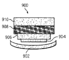
次に図9を参照し、複合材ストリップの断面図を、有利な実施形態に従って図示する。この例では、複合材ストリップ900は、複合材部品上への貼付けまたは使用前に、予備硬化され得る。
With reference now to FIG. 9, a cross-sectional view of a composite strip is depicted in accordance with an advantageous embodiment. In this example, the
この例では、複合材ストリップ900は、剥離プライ層902、テープ層904、テープ層906、生地層908、およびサーフェイサー層910を含み得る。この特定の例では、テープ層904が最小幅を有し得る。テープ層906は二番目に幅が小さく、生地層908は最大幅を有し得る。
In this example, the
この特定の例では、剥離プライ層902の幅は約3.5インチであり得る。テープ層904の幅は約1.0インチであり、テープ層906の幅は約2.0インチであり得る。生地層908の幅は、この例では約3.0インチであり得る。サーフェイサー層910の幅は約3.0インチであり得る。剥離プライ層902は、接着剤層が付加された状態で複合材部品の表面に貼付けられる前に除去し得る。
In this particular example, the width of the
次に図10を参照し、複合材ストリップの別の例の断面図を、有利な実施形態に従って図示する。この例では、複合材ストリップ1000は、剥離プライ層1002、テープ層1004、テープ層1006、生地層1008、サーフェイサー層1010、および剥離プライ層1012を含む。この特定の例では、剥離プライ層1012の幅は約3.5インチであり得る。サーフェイサー層1010の幅は約3.0インチであり得る。生地層1008の幅は約3.0インチであり得る。テープ層1006の幅は約2.0インチであり、テープ層1004の幅は約1.0インチであり得る。剥離プライ層1002の幅は、この例では約3.5インチであり得る。
With reference now to FIG. 10, a cross-sectional view of another example of a composite strip is depicted in accordance with an advantageous embodiment. In this example,
図7〜図10に示す異なる種類の層および幅は、実施し得るいくつかの異なる構成を例示する目的で示される。これらの例は、層を選択し得る方法または幅を限定するものではない。別の例では、当て板シームが位置することが予定され得る領域に使用するために先細りになった複合材ストリップをもたらすために、幅が異なる層の一実施形態を例示する。 The different types of layers and widths shown in FIGS. 7-10 are shown for purposes of illustrating several different configurations that may be implemented. These examples do not limit the method or width by which the layers can be selected. In another example, one embodiment of layers having different widths is illustrated to provide a composite strip that is tapered for use in an area where a patch plate seam can be expected to be located.
これらの例では、複合材ストリップの長さは約60インチであり得る。さらに、これらの例において、0度プライ方向は複合材ストリップの長さに平行であり得る。これらの例において、テープ材料の最適な利用法の1つは、外側モールドライン面内の繊維方向が90度または当て板シームの長さに垂直な状態での使用であり得る
生地層およびテープ層において使用し得る材料のいくつかの例は、たとえば限定はしないが、カーボン、ファイバガラス、ボロン、セラミック、およびアラミドを含む。これら
の種類の層に存在し得る樹脂は、たとえばアルキドポリエステル、エポキシ、ユリアホルムアルデヒド、液晶、ポリテトラフルオロエチレン、ポリエーテルエーテルケトン、ポリエーテルスルホンを含み得る。図示した例において使用される接着膜層は、エポキシの形態を取り得る。一部の樹脂/プリプレグ系では、プリプレグ中の樹脂は自己接着性と考えられ得るため、接着膜は必要ではない。剥離プライ層は、別の例ではナイロンまたはポリエステルを使用して形成され得る。
In these examples, the length of the composite strip can be about 60 inches. Further, in these examples, the 0 degree ply direction may be parallel to the length of the composite strip. In these examples, one of the best uses of the tape material may be use with the fiber orientation in the outer mold line plane being 90 degrees or perpendicular to the length of the backing plate seam. Some examples of materials that can be used in include, but are not limited to, carbon, fiberglass, boron, ceramic, and aramid. Resins that may be present in these types of layers may include, for example, alkyd polyesters, epoxies, urea formaldehyde, liquid crystals, polytetrafluoroethylene, polyetheretherketone, polyethersulfone. The adhesive film layer used in the illustrated example can take the form of an epoxy. In some resin / prepreg systems, an adhesive film is not necessary because the resin in the prepreg may be considered self-adhesive. The release ply layer can be formed using nylon or polyester in another example.
これらの例では、生地およびテープはプリプレグ部品であり得る。他の例において、複合材ストリップは、乾燥生地および/または粘着性を付与した生地の樹脂注入によって製造してもよい。 In these examples, the fabric and tape can be prepreg parts. In other examples, the composite strip may be made by resin injection of a dry dough and / or a tacky dough.
次に図11を参照し、複合材ストリップを作製するための処理のフローチャートを有利な実施形態に従って図示する。図11に示す処理を用いて、図6の複合材ストリップ604、または図7もしくは図8の複合材ストリップ700などの複合材ストリップを作製し得る。
Referring now to FIG. 11, a flowchart of a process for making a composite strip is depicted in accordance with an advantageous embodiment. The process shown in FIG. 11 may be used to make a composite strip such as
複合材ストリップの層のための複合材料を選択することによって処理が開始される(動作1100)。動作1100は、材料の種類および材料の寸法の選択を含み得る。生地、テープ、剥離プライまたは他の材料の選択を行ない得る。選択される寸法は、長さ、幅、および厚さを含み得る。
The process begins by selecting a composite material for a layer of composite strip (operation 1100).
この例では、第1の層は複合材生地の形態を取り得る。もちろん、実施例によっては他の種類の複合材料を使用してもよい。この例では、ベースは図7のベースプレート702などのベースであり得る。実施例によっては、ストリップはベース上に既に存在するストリップまたは剥離プライ層上に配置してもよい。選択された複合材料のストリップをベース上に配置して、層を形成する(動作1102)。ストリップは、最初の層に続く層として、ベース上の別の層上に配置してもよい。
In this example, the first layer may take the form of a composite dough. Of course, other types of composite materials may be used in some embodiments. In this example, the base may be a base such as
次に、複合材ストリップに追加の層が必要かどうかを判断する(動作1104)。追加の層が必要であれば、処理は動作1100に戻り、複合材ストリップの次の層のための別の材料を選択する。別の層を選択する際、生地、テープ、剥離プライ、サーフェイサー、または他の材料を選択し得る。この選択は、この次の層の寸法も含み得る。この次の層の幅は、複合材ストリップを先細りにするために先の層よりも小さくてもよい。
Next, a determination is made as to whether additional layers are required in the composite strip (operation 1104). If additional layers are needed, the process returns to
再び動作1104を参照し、追加の層が必要でなければ、複合材ストリップを硬化させる(動作1106)。その後、処理が終了する。
Referring back to
次に図12を参照し、複合材部品を製造するための処理を有利な実施形態に従って図示する。図12に例示する処理を用いて、図3の複合材部品300などの複合材部品を作製し得る。
Referring now to FIG. 12, a process for manufacturing a composite part is illustrated in accordance with an advantageous embodiment. Using the process illustrated in FIG. 12, a composite part, such as
当て板シームが位置することが予定され得る複合材部品の表面上に、予備硬化複合材ストリップを配置することによって、処理が開始される(動作1200)。次に、予備硬化複合材ストリップが複合材部品の表面に接合される(動作1202)。接合は、これらの例では接着剤層の使用によって行ない得る。当て板シームは、複合材部品上に配置された隣接する2枚の当て板の間の隙間が位置することが予定される領域またはセクションであり得る。次に、当て板を複合材部品上に配置する(動作1204)。その後、複合材部品を硬化させ(動作1206)、処理が終了する。 The process begins by placing a pre-cured composite strip on the surface of the composite part where the cauldron seam can be expected to be located (operation 1200). Next, the precured composite strip is bonded to the surface of the composite part (operation 1202). Bonding can be accomplished by the use of an adhesive layer in these examples. A caul plate seam can be an area or section where a gap between two adjacent caul plates disposed on a composite part is to be located. Next, a backing plate is placed on the composite part (operation 1204). Thereafter, the composite part is cured (operation 1206), and the process ends.
図12に例示した異なるステップは、複合材部品を所望量の表面仕上げまたは外観で製
造する際に必要なステップの一部のみを示す。もちろん、複合材部品を形成する際と複合材部品の硬化の準備を行う際との両方において、他のステップを複合材部品の準備に含んでもよい。
The different steps illustrated in FIG. 12 show only some of the steps necessary to produce a composite part with the desired amount of surface finish or appearance. Of course, other steps may be included in the preparation of the composite part both in forming the composite part and in preparing the composite part for curing.
このように、別の有利な実施形態によって、予備硬化複合材ストリップを複合材部品に貼付けるための方法および装置がもたらされる。熱硬化樹脂を有する予備硬化複合材ストリップは、当て板シームが位置することが予定される複合材部品の一部分の表面上に配置され得る。当て板シームを形成するために、複合材ストリップを配置した後で当て板を複合材部品上に配置してもよい。当て板を複合材部品上に配置した後で、複合材部品を硬化させてもよい。 Thus, another advantageous embodiment provides a method and apparatus for applying a precured composite strip to a composite part. A pre-cured composite strip with thermoset resin can be placed on the surface of the portion of the composite part where the cauldron seam is expected to be located. To form the caul plate seam, the caul plate may be placed on the composite part after the composite strip is placed. After placing the backing plate on the composite part, the composite part may be cured.
このように、別の有利な実施形態により、完成した複合材部品上の不整合が減少し得る。別の例は、有利な実施形態のすべてまたは一部において見られ得る特徴を示す。これらの特徴の異なる組合せを用いて、複合材部品の表面の外観における不整合を減少させ得る。 Thus, another advantageous embodiment may reduce misalignment on the finished composite part. Another example shows features that may be found in all or part of the advantageous embodiments. Different combinations of these features can be used to reduce inconsistencies in the surface appearance of the composite part.
異なる有利な実施形態の説明を例示および説明の目的で示したが、網羅するものではなく、実施形態を開示した形態に限定するものでもない。多くの修正および変形が当業者には明らかであろう。たとえば、図示した実施形態によれば、当該方法および装置を複合材胴体の製造に適用し得る。別の有利な実施形態を、他の部品またはパーツ上の欠陥を減少させるのに適用してもよい。たとえば、一部の有利な実施形態を、他の部材、たとえば限定はしないが航空機の翼または尾翼に適用し得る。さらに、別の有利な実施形態は、他の有利な実施形態と比べて異なる利点をもたらし得る。選択される実施形態は、本開示の原理、実際の用途を最もよく説明し、かつさまざまな修正を含むさまざまな実施形態が意図される特定の使用に適することを当業者に理解させるために、選択および説明される。 The description of the different advantageous embodiments has been presented for purposes of illustration and description, but is not intended to be exhaustive or limited to the embodiments disclosed. Many modifications and variations will be apparent to practitioners skilled in this art. For example, according to the illustrated embodiment, the method and apparatus can be applied to the manufacture of a composite body. Another advantageous embodiment may be applied to reduce defects on other parts or parts. For example, some advantageous embodiments may be applied to other components, such as but not limited to aircraft wings or tail wings. Furthermore, another advantageous embodiment may provide different advantages compared to the other advantageous embodiments. The selected embodiment best describes the principles of this disclosure, the actual application, and allows those skilled in the art to understand that various embodiments including various modifications are suitable for the particular use intended. Selected and explained.
300 複合材部品、302 モールド、304 表面、306 複合材ストリップ、308,310 当て板、312 当て板シーム、314 炉。 300 composite parts, 302 mold, 304 surface, 306 composite strip, 308,310 butt plate, 312 butt plate seam, 314 furnace.
Claims (8)
前記予備硬化複合材ストリップを、複合材部品の表面上に配置するステップと、
予備硬化複合材ストリップを配置した後に当て板を複合材部品の表面及び前記予備硬化複合材ストリップの表面上に配置して、当て板の端部間に当て板シームを形成するステップであって、前記予備硬化複合材ストリップが当て板シームの位置で露出するステップと、
当て板を複合材部品上に配置した後、複合材部品を硬化させるステップとを備える、方法。 A method for applying a precured composite strip to a composite part, comprising:
Placing the pre-cured composite strip on the surface of a composite part;
Placing a caul plate after placing the pre-cured composite strip on the surface of the composite part and the surface of the pre-cured composite strip to form a caul plate seam between the ends of the caul plate, Exposing the pre-cured composite strip at the location of a patch plate seam;
Curing the composite part after placing the backing plate on the composite part.
予備硬化複合材ストリップから剥離プライ層を除去するステップと、
予備硬化複合材ストリップの表面、および複合材部品の表面の間において、複合材部品の表面に、予備硬化複合材ストリップを接着剤層によって付着させるステップとを含む、請求項1に記載の方法。 Placing the pre-cured composite strip comprises:
Removing the release ply layer from the precured composite strip;
The method of claim 1, comprising: attaching a pre-cured composite strip with an adhesive layer to the surface of the composite part between the surface of the pre-cured composite strip and the surface of the composite part.
予備硬化複合材ストリップから第2の剥離プライ層を除去して、第2の表面を露出させるステップと、
第2の表面上にサーフェイサー層を配置するステップとを含む、請求項3に記載の方法。 The release ply layer is a first release ply layer, and the step of placing the pre-cured composite strip further comprises
Removing the second release ply layer from the pre-cured composite strip to expose the second surface;
And disposing a surfacer layer on the second surface.
複合材ストリップの組を硬化させて、予備硬化複合材ストリップを形成するステップとをさらに備える、請求項1に記載の方法。 Forming a set of composite strips;
The method of claim 1, further comprising curing the set of composite strips to form a pre-cured composite strip.
第1の幅を有する第1の複合材生地層を配置するステップと、
第1の幅よりも小さい第2の幅を有する複合材テープ層を前記第1の複合材生地層上に配置するステップと、
第2の幅よりも小さい第3の幅を有する第2の複合材生地層を前記複合材テープ層上に配置するステップと、
を含むステップを含む、請求項6に記載の方法。 Forming the composite strip set comprises:
Placing a first composite fabric layer having a first width;
Disposing a composite tape layer having a second width less than the first width on the first composite fabric layer;
Disposing a second composite fabric layer having a third width less than the second width on the composite tape layer;
The method of claim 6, comprising the steps of:
複合材生地層を複合材テープ層上に配置するステップと、
第1の剥離プライ層を前記複合材生地層上に配置するステップと、
第2剥離プライ層を前記複合材テープ層の下に配置するステップと、
を含む、請求項6に記載の方法。 Forming the composite strip set comprises:
Placing the composite fabric layer on the composite tape layer;
Placing a first release ply layer on the composite fabric layer;
Disposing a second release ply layer under the composite tape layer;
The method of claim 6 comprising:
Applications Claiming Priority (2)
| Application Number | Priority Date | Filing Date | Title |
|---|---|---|---|
| US11/832,956 | 2007-08-02 | ||
| US11/832,956 US8016970B2 (en) | 2007-08-02 | 2007-08-02 | Method for applying a pre-cured composite strip to a composite component to minimize inconsistencies appearing on a surface of the composite component |
Publications (2)
| Publication Number | Publication Date |
|---|---|
| JP2009035001A JP2009035001A (en) | 2009-02-19 |
| JP4960318B2 true JP4960318B2 (en) | 2012-06-27 |
Family
ID=40020224
Family Applications (1)
| Application Number | Title | Priority Date | Filing Date |
|---|---|---|---|
| JP2008198002A Active JP4960318B2 (en) | 2007-08-02 | 2008-07-31 | Method and apparatus for minimizing misalignments appearing on the surface of composite parts |
Country Status (4)
| Country | Link |
|---|---|
| US (2) | US8016970B2 (en) |
| EP (1) | EP2020286B1 (en) |
| JP (1) | JP4960318B2 (en) |
| ES (1) | ES2805138T3 (en) |
Families Citing this family (21)
| Publication number | Priority date | Publication date | Assignee | Title |
|---|---|---|---|---|
| US8016970B2 (en) * | 2007-08-02 | 2011-09-13 | The Boeing Company | Method for applying a pre-cured composite strip to a composite component to minimize inconsistencies appearing on a surface of the composite component |
| EP2660031B1 (en) * | 2010-12-27 | 2020-03-25 | Kawasaki Jukogyo Kabushiki Kaisha | Molding jig and molding method |
| JP5698526B2 (en) * | 2010-12-27 | 2015-04-08 | 川崎重工業株式会社 | Mold |
| DE102011010384B4 (en) * | 2011-02-05 | 2015-06-11 | Premium Aerotec Gmbh | Process for producing a fiber composite component |
| US9126355B2 (en) | 2012-05-02 | 2015-09-08 | Spirit Aerosystems, Inc. | Composite material part manufacturing process using removable and retainable material |
| US9517594B2 (en) * | 2012-10-04 | 2016-12-13 | The Boeing Company | Composite structure having a stabilizing element |
| US10201959B2 (en) * | 2015-01-30 | 2019-02-12 | The Boeing Company | Gradient curing of composite laminate parts |
| US10197392B2 (en) | 2015-06-23 | 2019-02-05 | The Boeing Company | Automated resin ridge reduction system |
| DE102015225467B4 (en) * | 2015-12-16 | 2019-12-19 | Airbus Defence and Space GmbH | Coated composite component and method for producing a coated composite component |
| US10226891B2 (en) * | 2016-08-01 | 2019-03-12 | The Boeing Company | Methods, system and apparatuses for in situ removal of window distortion |
| US11274066B1 (en) * | 2017-11-30 | 2022-03-15 | Goodman Technologies LLC | Ceramic armor and other structures manufactured using ceramic nano-pastes |
| US11034064B2 (en) * | 2018-08-29 | 2021-06-15 | The Boeing Company | Overlapping caul plates and method for composite manufacturing |
| US11358348B2 (en) | 2019-01-02 | 2022-06-14 | The Boeing Company | Mold insert for use with a mandrel for forming a composite structure |
| FR3100738B1 (en) * | 2019-09-12 | 2021-08-20 | Safran Aircraft Engines | Method of closing an injection mold using anti-pinch strips |
| CN111497279A (en) * | 2020-04-26 | 2020-08-07 | 吉林联科特种石墨材料有限公司 | Vacuum forming method of asphalt-based heat-insulating cylinder |
| NL2027435B1 (en) * | 2021-01-26 | 2022-08-19 | Boeing Co | Apparatus and method for processing a composite structure |
| EP4000885B1 (en) * | 2020-11-18 | 2024-01-10 | The Boeing Company | Method for processing a composite structure |
| EP4000884B1 (en) * | 2020-11-18 | 2024-01-10 | The Boeing Company | Apparatus for processing a composite structure |
| NL2027434B1 (en) * | 2021-01-26 | 2022-08-19 | Boeing Co | Apparatus and method for processing a composite structure |
| US11938689B2 (en) | 2020-11-18 | 2024-03-26 | The Boeing Company | Apparatus and method for processing a composite structure |
| US12070915B2 (en) | 2021-01-04 | 2024-08-27 | The Boeing Company | Autoclave system, bladder assembly, and associated method for forming a part |
Family Cites Families (29)
| Publication number | Priority date | Publication date | Assignee | Title |
|---|---|---|---|---|
| US3865662A (en) * | 1973-04-06 | 1975-02-11 | Allied Chem | Method for sealing shell-like thermoplastic objects |
| US4084029A (en) * | 1977-07-25 | 1978-04-11 | The Boeing Company | Sine wave beam web and method of manufacture |
| US4331723A (en) * | 1980-11-05 | 1982-05-25 | The Boeing Company | Advanced composite |
| US4589562A (en) * | 1981-05-04 | 1986-05-20 | Fawley Norman | Structures reinforced by a composite material |
| US4401495A (en) * | 1981-09-28 | 1983-08-30 | The Boeing Company | Method of winding composite panels |
| US4734146A (en) * | 1986-03-31 | 1988-03-29 | Rockwell International Corporation | Method of producing a composite sine wave beam |
| JPH05156656A (en) * | 1991-12-10 | 1993-06-22 | Nippon Boshoku Kogyo Kk | Corrosion protective method for steel pipe pile |
| US5242523A (en) * | 1992-05-14 | 1993-09-07 | The Boeing Company | Caul and method for bonding and curing intricate composite structures |
| CA2181497C (en) * | 1996-07-18 | 2002-04-09 | Fernand Ellyin | Carbon fiber-reinforced polymer patch for defect repair of a structural steel component |
| CA2598765C (en) * | 1997-01-29 | 2013-01-22 | Hawker Beechcraft Corporation | Method and apparatus for manufacturing composite structures |
| US6692681B1 (en) * | 1997-01-29 | 2004-02-17 | Raytheon Aircraft Company | Method and apparatus for manufacturing composite structures |
| JPH10278185A (en) * | 1997-04-10 | 1998-10-20 | Mitsubishi Electric Corp | Manufacture of sandwich structure |
| TW467940B (en) * | 1997-10-14 | 2001-12-11 | Toray Industries | Thermosetting resin composition for carbon-fiber reinforced composite material |
| US6284089B1 (en) * | 1997-12-23 | 2001-09-04 | The Boeing Company | Thermoplastic seam welds |
| US6513757B1 (en) * | 1999-07-19 | 2003-02-04 | Fuji Jukogyo Kabushiki Kaisha | Wing of composite material and method of fabricating the same |
| WO2001062495A2 (en) * | 2000-02-25 | 2001-08-30 | The Boeing Company | Laminated composite radius filler |
| ES2185443B1 (en) * | 2000-03-07 | 2004-09-01 | Airbus España S.L. | PROCEDURE FOR MANUFACTURING OF PREPARED PARTS IN COMPOSITE MATERIAL WITH RIGIDIZERS APPLIED IN FRESH STATE. |
| JP4318381B2 (en) * | 2000-04-27 | 2009-08-19 | 本田技研工業株式会社 | Manufacturing method of fuselage structure made of fiber reinforced composite material, and fuselage structure manufactured thereby |
| US6821368B2 (en) * | 2001-10-09 | 2004-11-23 | Lockheed Martin Corporation | Co-bonded joint with Z-pins |
| US7204951B2 (en) * | 2002-07-30 | 2007-04-17 | Rocky Mountain Composites, Inc. | Method of assembling a single piece co-cured structure |
| US8778479B2 (en) * | 2003-03-06 | 2014-07-15 | Vestas Wind Systems A/S | Pre-form and method of preparing a pre-form |
| US7249943B2 (en) * | 2003-08-01 | 2007-07-31 | Alliant Techsystems Inc. | Apparatus for forming composite stiffeners and reinforcing structures |
| JP2005067089A (en) * | 2003-08-26 | 2005-03-17 | Universal Shipbuilding Corp | Method for molding molded product |
| US7228611B2 (en) * | 2003-11-18 | 2007-06-12 | The Boeing Company | Method of transferring large uncured composite laminates |
| US7080805B2 (en) * | 2004-05-05 | 2006-07-25 | The Boeing Company | Stiffened structures and associated methods |
| US7531058B2 (en) * | 2005-02-24 | 2009-05-12 | The Boeing Company | Reinforced rampdown for composite structural member and method for same |
| US8691037B2 (en) * | 2006-12-14 | 2014-04-08 | The Boeing Company | Method for minimizing fiber distortion during fabrication of one-piece composite barrel section |
| US8016230B2 (en) * | 2007-05-11 | 2011-09-13 | The Boeing Company | Fastner-free primary structural joint for sandwich panels |
| US8016970B2 (en) * | 2007-08-02 | 2011-09-13 | The Boeing Company | Method for applying a pre-cured composite strip to a composite component to minimize inconsistencies appearing on a surface of the composite component |
-
2007
- 2007-08-02 US US11/832,956 patent/US8016970B2/en active Active
-
2008
- 2008-07-25 ES ES08252538T patent/ES2805138T3/en active Active
- 2008-07-25 EP EP08252538.7A patent/EP2020286B1/en active Active
- 2008-07-31 JP JP2008198002A patent/JP4960318B2/en active Active
-
2011
- 2011-03-29 US US13/074,430 patent/US9039858B2/en active Active
Also Published As
| Publication number | Publication date |
|---|---|
| JP2009035001A (en) | 2009-02-19 |
| EP2020286A3 (en) | 2017-04-19 |
| EP2020286B1 (en) | 2020-05-06 |
| US8016970B2 (en) | 2011-09-13 |
| US9039858B2 (en) | 2015-05-26 |
| EP2020286A2 (en) | 2009-02-04 |
| US20110195232A1 (en) | 2011-08-11 |
| US20090297788A1 (en) | 2009-12-03 |
| ES2805138T3 (en) | 2021-02-10 |
Similar Documents
| Publication | Publication Date | Title |
|---|---|---|
| JP4960318B2 (en) | Method and apparatus for minimizing misalignments appearing on the surface of composite parts | |
| EP2903801B1 (en) | Composite structure having a stabilizing element | |
| US7097731B2 (en) | Method of manufacturing a hollow section, grid stiffened panel | |
| US11220069B2 (en) | Composite laminate structures | |
| US9051062B1 (en) | Assembly using skeleton structure | |
| US9649820B1 (en) | Assembly using skeleton structure | |
| US11034064B2 (en) | Overlapping caul plates and method for composite manufacturing | |
| US8715560B2 (en) | Method to control thickness in composite parts cured on closed angle tool | |
| US11738526B2 (en) | Method for using composite tooling to manufacture composite parts | |
| US9545758B2 (en) | Two piece mandrel manufacturing system | |
| US10744724B2 (en) | Composite aircraft manufacturing tooling and methods using articulating mandrels | |
| US11981839B2 (en) | Method and apparatus for fabrication of composite tooling | |
| US11981426B2 (en) | Composite spars with integrated sacrificial surfaces | |
| US11110671B2 (en) | Layup support configured to provide support for laying up composite material | |
| EP3835041B1 (en) | Flyaway stringer end caps | |
| US10913221B2 (en) | Shaping a radius filler against a mandrel | |
| US12285920B2 (en) | Method and apparatus for fabrication of composite tooling | |
| US11718047B2 (en) | Flyaway stringer end caps | |
| JP2024077623A (en) | Apparatus and method for manufacturing a composite part to provide a smooth joining surface of the composite part - Patents.com |
Legal Events
| Date | Code | Title | Description |
|---|---|---|---|
| RD03 | Notification of appointment of power of attorney |
Free format text: JAPANESE INTERMEDIATE CODE: A7423 Effective date: 20091111 |
|
| A521 | Request for written amendment filed |
Free format text: JAPANESE INTERMEDIATE CODE: A821 Effective date: 20100303 |
|
| RD04 | Notification of resignation of power of attorney |
Free format text: JAPANESE INTERMEDIATE CODE: A7424 Effective date: 20100303 |
|
| A977 | Report on retrieval |
Free format text: JAPANESE INTERMEDIATE CODE: A971007 Effective date: 20110303 |
|
| A131 | Notification of reasons for refusal |
Free format text: JAPANESE INTERMEDIATE CODE: A131 Effective date: 20110329 |
|
| A601 | Written request for extension of time |
Free format text: JAPANESE INTERMEDIATE CODE: A601 Effective date: 20110627 |
|
| A602 | Written permission of extension of time |
Free format text: JAPANESE INTERMEDIATE CODE: A602 Effective date: 20110630 |
|
| A601 | Written request for extension of time |
Free format text: JAPANESE INTERMEDIATE CODE: A601 Effective date: 20110727 |
|
| A602 | Written permission of extension of time |
Free format text: JAPANESE INTERMEDIATE CODE: A602 Effective date: 20110801 |
|
| A521 | Request for written amendment filed |
Free format text: JAPANESE INTERMEDIATE CODE: A523 Effective date: 20110811 |
|
| A131 | Notification of reasons for refusal |
Free format text: JAPANESE INTERMEDIATE CODE: A131 Effective date: 20110920 |
|
| A601 | Written request for extension of time |
Free format text: JAPANESE INTERMEDIATE CODE: A601 Effective date: 20111110 |
|
| A602 | Written permission of extension of time |
Free format text: JAPANESE INTERMEDIATE CODE: A602 Effective date: 20111115 |
|
| A521 | Request for written amendment filed |
Free format text: JAPANESE INTERMEDIATE CODE: A523 Effective date: 20120117 |
|
| TRDD | Decision of grant or rejection written | ||
| A01 | Written decision to grant a patent or to grant a registration (utility model) |
Free format text: JAPANESE INTERMEDIATE CODE: A01 Effective date: 20120221 |
|
| A01 | Written decision to grant a patent or to grant a registration (utility model) |
Free format text: JAPANESE INTERMEDIATE CODE: A01 |
|
| A61 | First payment of annual fees (during grant procedure) |
Free format text: JAPANESE INTERMEDIATE CODE: A61 Effective date: 20120322 |
|
| FPAY | Renewal fee payment (event date is renewal date of database) |
Free format text: PAYMENT UNTIL: 20150330 Year of fee payment: 3 |
|
| R150 | Certificate of patent or registration of utility model |
Ref document number: 4960318 Country of ref document: JP Free format text: JAPANESE INTERMEDIATE CODE: R150 Free format text: JAPANESE INTERMEDIATE CODE: R150 |
|
| R250 | Receipt of annual fees |
Free format text: JAPANESE INTERMEDIATE CODE: R250 |
|
| R250 | Receipt of annual fees |
Free format text: JAPANESE INTERMEDIATE CODE: R250 |
|
| R250 | Receipt of annual fees |
Free format text: JAPANESE INTERMEDIATE CODE: R250 |
|
| R250 | Receipt of annual fees |
Free format text: JAPANESE INTERMEDIATE CODE: R250 |
|
| R250 | Receipt of annual fees |
Free format text: JAPANESE INTERMEDIATE CODE: R250 |
|
| R250 | Receipt of annual fees |
Free format text: JAPANESE INTERMEDIATE CODE: R250 |
|
| R250 | Receipt of annual fees |
Free format text: JAPANESE INTERMEDIATE CODE: R250 |
|
| R250 | Receipt of annual fees |
Free format text: JAPANESE INTERMEDIATE CODE: R250 |
|
| R250 | Receipt of annual fees |
Free format text: JAPANESE INTERMEDIATE CODE: R250 |
|
| R250 | Receipt of annual fees |
Free format text: JAPANESE INTERMEDIATE CODE: R250 |
|
| R250 | Receipt of annual fees |
Free format text: JAPANESE INTERMEDIATE CODE: R250 |