JP4958635B2 - Imaging apparatus and control method thereof - Google Patents
Imaging apparatus and control method thereof Download PDFInfo
- Publication number
- JP4958635B2 JP4958635B2 JP2007133888A JP2007133888A JP4958635B2 JP 4958635 B2 JP4958635 B2 JP 4958635B2 JP 2007133888 A JP2007133888 A JP 2007133888A JP 2007133888 A JP2007133888 A JP 2007133888A JP 4958635 B2 JP4958635 B2 JP 4958635B2
- Authority
- JP
- Japan
- Prior art keywords
- correction
- image data
- light amount
- peripheral light
- predetermined value
- Prior art date
- Legal status (The legal status is an assumption and is not a legal conclusion. Google has not performed a legal analysis and makes no representation as to the accuracy of the status listed.)
- Expired - Fee Related
Links
Images


Classifications
-
- H—ELECTRICITY
- H04—ELECTRIC COMMUNICATION TECHNIQUE
- H04N—PICTORIAL COMMUNICATION, e.g. TELEVISION
- H04N23/00—Cameras or camera modules comprising electronic image sensors; Control thereof
- H04N23/60—Control of cameras or camera modules
-
- H—ELECTRICITY
- H04—ELECTRIC COMMUNICATION TECHNIQUE
- H04N—PICTORIAL COMMUNICATION, e.g. TELEVISION
- H04N23/00—Cameras or camera modules comprising electronic image sensors; Control thereof
- H04N23/70—Circuitry for compensating brightness variation in the scene
- H04N23/75—Circuitry for compensating brightness variation in the scene by influencing optical camera components
-
- H—ELECTRICITY
- H04—ELECTRIC COMMUNICATION TECHNIQUE
- H04N—PICTORIAL COMMUNICATION, e.g. TELEVISION
- H04N23/00—Cameras or camera modules comprising electronic image sensors; Control thereof
- H04N23/60—Control of cameras or camera modules
- H04N23/68—Control of cameras or camera modules for stable pick-up of the scene, e.g. compensating for camera body vibrations
- H04N23/681—Motion detection
- H04N23/6812—Motion detection based on additional sensors, e.g. acceleration sensors
-
- H—ELECTRICITY
- H04—ELECTRIC COMMUNICATION TECHNIQUE
- H04N—PICTORIAL COMMUNICATION, e.g. TELEVISION
- H04N23/00—Cameras or camera modules comprising electronic image sensors; Control thereof
- H04N23/60—Control of cameras or camera modules
- H04N23/68—Control of cameras or camera modules for stable pick-up of the scene, e.g. compensating for camera body vibrations
- H04N23/682—Vibration or motion blur correction
- H04N23/685—Vibration or motion blur correction performed by mechanical compensation
- H04N23/687—Vibration or motion blur correction performed by mechanical compensation by shifting the lens or sensor position
-
- H—ELECTRICITY
- H04—ELECTRIC COMMUNICATION TECHNIQUE
- H04N—PICTORIAL COMMUNICATION, e.g. TELEVISION
- H04N25/00—Circuitry of solid-state image sensors [SSIS]; Control thereof
- H04N25/60—Noise processing, e.g. detecting, correcting, reducing or removing noise
- H04N25/61—Noise processing, e.g. detecting, correcting, reducing or removing noise the noise originating only from the lens unit, e.g. flare, shading, vignetting or "cos4"
Description
本発明は、撮像装置及びその制御方法に関し、周辺光量落ちを低減させた良好な画像を提供できる撮像装置及びその制御方法に関する。 The present invention relates to an image pickup apparatus and a control method thereof, and more particularly to an image pickup apparatus capable of providing a good image with reduced peripheral light loss and a control method thereof.
レンズを介して光学像を得ることで被写体を撮影する撮像装置では、撮影された被写体の画像において、その画像の中心部から画像周辺部に行くにしたがって、光量が低下する所謂、周辺光量落ち現象が発生する。 In an imaging device that captures an object by obtaining an optical image through a lens, the so-called peripheral light intensity drop phenomenon in which the amount of light decreases as it goes from the center of the captured image to the periphery of the image. Will occur.
また、周辺光量落ち現象は、撮像装置が備えるレンズの特性と、固体撮像素子の特性の関係で決まることが知られている。 Further, it is known that the peripheral light amount drop phenomenon is determined by the relationship between the characteristics of the lens provided in the imaging apparatus and the characteristics of the solid-state imaging device.
具体的には、有効像円(光が均一に当たる領域)に対する固体撮像素子の位置との関係で、周辺光量落ち量が一意的に決まる。但し、この場合は、固体撮像素子の有効画素中心と、レンズの光軸中心が一致していることが前提になる。 Specifically, the peripheral light amount drop amount is uniquely determined by the relationship with the position of the solid-state imaging device with respect to the effective image circle (the region where the light hits uniformly). However, in this case, it is a premise that the effective pixel center of the solid-state imaging device and the optical axis center of the lens are coincident.
また、周辺光量落ち量はレンズの絞り値にも依存し、開放側において光量の落ち具合が最も顕著である。これは、一般的なレンズ特性として、レンズ中心における入射光は、円形の光束のまま入射するが、レンズの隅における入射光は、常に隅を通っていくために光がけられてしまい、入射光は楕円状の光束になってしまい光量が低下する。そのため、絞りが開放状態の時には、レンズの隅をより多くの入射光が通るため、光のけられ現象がより顕著になる。このことから、絞り値が開放の場合に、周辺光量落ち現象の影響を大きく受ける。 The amount of decrease in the amount of peripheral light also depends on the aperture value of the lens, and the amount of decrease in the amount of light is most noticeable on the open side. This is because, as a general lens characteristic, the incident light at the center of the lens is incident as a circular light beam, but the incident light at the corners of the lens always passes through the corners, so the incident light is lost. Becomes an elliptical luminous flux, and the amount of light decreases. For this reason, when the aperture is in the open state, more incident light passes through the corners of the lens, so that the phenomenon of light scattering becomes more prominent. For this reason, when the aperture value is full, it is greatly affected by the phenomenon of the peripheral light amount drop.
この現象を回避するために、撮像装置が備えるレンズの有効像円が固体撮像素子が備える画素数に対して、充分大きくなるようなレンズを使用することが挙げられる。しかし、そのような条件を満たすレンズを使用すると、レンズ自体のサイズが大きくなり、撮像装置の小型化が困難となってしまう。 In order to avoid this phenomenon, it is possible to use a lens whose effective image circle of the lens included in the imaging device is sufficiently larger than the number of pixels included in the solid-state imaging device. However, when a lens satisfying such conditions is used, the size of the lens itself becomes large, and it is difficult to reduce the size of the imaging device.
また、撮像装置の小型化が求められ、大きなレンズを備えるのが困難になってきている中、撮像装置が備える固体撮像素子の画素数も急速に増えてきており、周辺光量落ち現象が顕著になってきている。 In addition, as the downsizing of the image pickup device is required and it is difficult to provide a large lens, the number of pixels of the solid-state image pickup device provided in the image pickup device is rapidly increasing, and the peripheral light amount drop phenomenon is remarkable. It has become to.
そこで、周辺光量落ち現象の影響を抑えつつ、撮像装置の小型化を実現するための技術が提案されている(特許文献1参照)。 Therefore, a technique for realizing downsizing of the image pickup apparatus while suppressing the influence of the peripheral light amount drop phenomenon has been proposed (see Patent Document 1).
特許文献1で開示されている手法では、画面をブロック単位で分割してブロック毎に絞り値に対応した周辺光量補正係数を適用するため、画面周辺部の四角の周辺光量落ち量が均一でなくても補正が可能となる。結果として、周辺光量落ちが発生しない良好な画質を提供することができる。
In the method disclosed in
また、撮像装置が光学式像振れ補正機能や電子式像振れ補正機能を備えている場合、画面中心部に対する画面周辺部の光量落ち量も変動するという問題がある。 In addition, when the image pickup apparatus has an optical image blur correction function or an electronic image blur correction function, there is a problem in that the amount of light loss at the periphery of the screen relative to the center of the screen also varies.
この問題は光学式像振れ補正を行う際にはレンズをシフトする為、レンズの中心と固体撮像素子の中心とで、ずれが生じてしまうことに起因している。そのため、光軸中心のずれにより、周辺光量落ち量が画面周辺部において均一にはならずに、レンズのシフト状態により、大きく異なってくる場合がある。以上の理由から、光学式像ぶれ補正を行う際に、レンズシフト量に応じて、周辺光量落ちの発生レベル(頻度)も変化する。これは、画素の切り出し位置を変化させて振れ補正を行う電子式像ぶれ補正に関しても、同様にいえることである。 This problem is caused by shifting the lens between the center of the lens and the center of the solid-state imaging device because the lens is shifted when performing optical image blur correction. For this reason, due to the shift of the optical axis center, the peripheral light amount drop amount may not be uniform in the peripheral portion of the screen, but may vary greatly depending on the lens shift state. For the above reasons, when optical image blur correction is performed, the generation level (frequency) of the peripheral light amount drop also changes according to the lens shift amount. This also applies to electronic image blur correction in which shake correction is performed by changing the pixel cut-out position.
このような問題に対応するため、撮像装置の光軸中心位置算出機能を備えることにより、光軸中心位置に応じて、周辺光量落ち補正量を変化させるという技術も提案されている(特許文献2参照)。
特許文献1で開示されている手法では、絞り値に対応したブロック毎の周辺光量補正係数を用いた周辺光量落ち補正機能が被写体撮影時に常時動作する。つまり、被写体撮影時の露出条件やズーム動作によって絞り値が動的に変化すれば、周辺光量落ち補正値も動的に変化することになる。
In the method disclosed in
しかし、被写体撮影時の露出状態に応じた補正係数を算出してから補正を行なうまでに、絞り値も変化することがあるため、補正の過不足が生じてしまうという問題がある。映像の見た目の連続性が重要である動画撮影において、これは大きな問題である。 However, since the aperture value may change from the calculation of the correction coefficient according to the exposure state at the time of photographing the subject to the correction, there is a problem in that the correction is excessive or insufficient. This is a major problem in video shooting where the visual continuity of video is important.
特許文献2で開示されている手法では、ユーザーが手持ちで動画を撮影する場合にも、常時像振れ補正機能は動作するため、像振れ補正量は動的に変化することになる。 In the method disclosed in Patent Document 2, the image blur correction function always operates even when the user holds a moving image, so the image blur correction amount changes dynamically.
つまり、光軸の位置算出結果に応じた補正係数を算出してから補正を行うまでに、被写体撮影時のユーザーの手ぶれ等により実際の光軸の位置も変化するため、補正の過不足が生じてしまうという問題がある。 In other words, the actual position of the optical axis changes due to camera shake when the subject is photographed after the correction coefficient corresponding to the optical axis position calculation result is calculated and correction is performed. There is a problem that it ends up.
本発明は上記問題点を鑑みてなされたものであり、安定的な周辺光量落ち補正を行うことを目的とする。 The present invention has been made in consideration of the above situation, and an object thereof to perform stable peripheral light amount drop correction.
上記目的を達成するために、本発明に係る撮像装置は、被写体を撮像して画像データを取得する撮像手段と、開口径を変化させて前記撮像手段の撮像面への入射光量を調整する絞り手段と、前記撮像手段により取得した画像データに対して周辺光量落ち補正を行う補正手段と、を有し、前記補正手段は、前記絞り手段の開口径を所定値以上の変化量で変化させている際に取得した画像データに対してよりも、前記開口径を前記所定値以上の変化量で変化させていない際に取得した画像データに対して強く前記周辺光量落ち補正を行い、前記開口径を小絞り側に変化させるときは前記開口径を開放側に変化させるときよりも前記所定値を小さくすることを特徴とする。
また、上記目的を達成するために、本発明に係る撮像装置は、被写体を撮像して画像データを取得する撮像手段と、開口径を変化させて前記撮像手段の撮像面への入射光量を調整する絞り手段と、画像のぶれを補正するぶれ補正手段と、前記撮像手段により取得した画像データに対して周辺光量落ち補正を行う補正手段と、を有し、前記補正手段は、前記絞り手段の開口径を第1の所定値以上の変化量で変化させている際に取得した画像データに対してよりも、前記開口径を前記第1の所定値以上の変化量で変化させていなくて前記ぶれ補正手段により第2の所定値以上の補正量でぶれ補正を行っていない際に取得した画像データに対して強く前記周辺光量落ち補正を行うことを特徴とする。
In order to achieve the above object, an imaging apparatus according to the present invention includes an imaging unit that captures an image of a subject and acquires image data, and a diaphragm that adjusts the amount of incident light on the imaging surface of the imaging unit by changing an aperture diameter. And correction means for performing a peripheral light amount drop correction on the image data acquired by the imaging means, and the correction means changes the aperture diameter of the diaphragm means by a change amount greater than a predetermined value. than the image data obtained when there, have rows the peripheral light amount drop correction strongly on the acquired image data when not the aperture diameter is varied by the predetermined value or more variation, the open When the aperture is changed to the small aperture side, the predetermined value is made smaller than when the aperture diameter is changed to the open side .
In order to achieve the above object, an image pickup apparatus according to the present invention adjusts the amount of incident light on the image pickup surface of the image pickup means by changing the aperture diameter by picking up an image of a subject and acquiring image data. A diaphragm unit that corrects image blur, and a correction unit that performs peripheral light amount drop correction on the image data acquired by the imaging unit. The correction unit includes: Compared to the image data acquired when the opening diameter is changed by a change amount greater than or equal to a first predetermined value, the opening diameter is not changed by a change amount greater than or equal to the first predetermined value. The peripheral light amount drop correction is strongly performed on image data acquired when the blur correction unit does not perform the blur correction with a correction amount equal to or greater than the second predetermined value.
また、上記目的を達成するために、本発明に係る撮像装置の制御方法は、被写体を撮像して画像データを取得する撮像手段と、開口径を変化させて前記撮像手段の撮像面への入射光量を調整する絞り手段と、を有する撮像装置の制御方法であって、前記撮像手段により取得した画像データに対して周辺光量落ち補正を行う補正ステップを有し、前記補正ステップは、前記絞り手段の開口径を所定値以上の変化量で変化させている際に取得した画像データに対してよりも、前記開口径を前記所定値以上の変化量で変化させていない際に取得した画像データに対して強く前記周辺光量落ち補正を行い、前記開口径を小絞り側に変化させるときは前記開口径を開放側に変化させるときよりも前記所定値を小さくすることを特徴とする。
また、上記目的を達成するために、本発明に係る撮像装置の制御方法は、被写体を撮像して画像データを取得する撮像手段と、開口径を変化させて前記撮像手段の撮像面への入射光量を調整する絞り手段と、画像のぶれを補正するぶれ補正手段と、を有する撮像装置の制御方法であって、前記撮像手段により取得した画像データに対して周辺光量落ち補正を行う補正ステップを有し、前記補正ステップは、前記絞り手段の開口径を第1の所定値以上の変化量で変化させている際に取得した画像データに対してよりも、前記開口径を前記第1の所定値以上の変化量で変化させていなくて前記ぶれ補正手段により第2の所定値以上の補正量でぶれ補正を行っていない際に取得した画像データに対して強く前記周辺光量落ち補正を行うことを特徴とする。
In order to achieve the above object, an imaging apparatus control method according to the present invention includes an imaging unit that captures an image of a subject and acquires image data, and an incident on an imaging surface of the imaging unit by changing an aperture diameter. A diaphragm unit that adjusts the amount of light, and a control method for the imaging apparatus, the image processing apparatus comprising: a correction step that performs a peripheral light amount drop correction on the image data acquired by the imaging unit; than the image data obtained the aperture diameter when is varied by a predetermined value or more variation, the opening diameter on the image data obtained when not changed by a change amount of the predetermined value or more There line the peripheral light amount drop correction strongly against, when changing the aperture diameter on the small aperture side is characterized by reducing the predetermined value than when changing the opening diameter on the open side.
In order to achieve the above object, an imaging apparatus control method according to the present invention includes an imaging unit that captures an image of a subject and acquires image data, and an incident on an imaging surface of the imaging unit by changing an aperture diameter. An image pickup apparatus control method comprising: a diaphragm unit that adjusts a light amount; and a shake correction unit that corrects a shake of an image, the correction step performing a peripheral light amount drop correction on image data acquired by the image pickup unit. And the correcting step sets the opening diameter to the first predetermined value rather than the image data acquired when the opening diameter of the aperture means is changed by a change amount greater than or equal to a first predetermined value. The marginal light amount drop correction is strongly performed on the image data acquired when the blur correction unit does not perform the blur correction with the correction amount equal to or greater than the second predetermined value without being changed by the variation amount equal to or greater than the value. With features That.
本発明のよれば、安定的な周辺光量落ち補正を行うことができる。 According to the present invention, stable peripheral light amount drop correction can be performed.
以下、添付図面を参照して本発明を実施するための最良の形態を詳細に説明する。ただし、本形態において例示される構成部品の寸法、形状、それらの相対配置などは、本発明が適用される装置の構成や各種条件により適宜変更されるべきものであり、本発明がそれらの例示に限定されるものではない。 The best mode for carrying out the present invention will be described below in detail with reference to the accompanying drawings. However, the dimensions, shapes, relative arrangements, and the like of the components exemplified in the present embodiment should be changed as appropriate according to the configuration of the apparatus to which the present invention is applied and various conditions. It is not limited to.
<第1の実施形態>
本発明の第1の実施形態について説明する。図1は第1の実施形態に係る撮像装置のブロック図である。
<First Embodiment>
A first embodiment of the present invention will be described. FIG. 1 is a block diagram of an imaging apparatus according to the first embodiment.
同図において、1はレンズ、3は光電変換機能を有するCCDセンサやCMOSセンサ等の固体撮像素子、2は固体撮像素子3への入射光量を調整する絞り手段としての絞りである。レンズ1を通った光信号は、絞り2を介して固体撮像素子3に入力される。9は、撮像装置と撮像装置全体の制御を行うCPUであり、本発明においては、補正データ取得手段としての機能も有する。5はCPU9によって制御され、例えば、3V振幅の転送パルスを水平同期信号HDに同期して、一定周期の信号を出力するタイミングジェネレータ(これよりTGという)である。
In the figure,
固体撮像素子3は、TG5より出力されるタイミングパルスにより駆動され、入力された光信号を電気信号に光電変換して出力する。 The solid-state imaging device 3 is driven by a timing pulse output from the TG 5, photoelectrically converts the input optical signal into an electrical signal, and outputs the electrical signal.
4は相関二重サンプリングを行なう不図示のCDSと、ゲイン制御を行なう不図示のAGCと、アナログ信号をデジタル信号に変換する不図示のA/D変換器で構成されたアナログフロントエンド(これよりAFEという)である。固体撮像素子3が出力した出力信号は、AFE4に入力され、デジタル信号に変換された後、周辺光量補正回路6に入力される。
4 is an analog front end composed of a CDS (not shown) that performs correlated double sampling, an AGC (not shown) that performs gain control, and an A / D converter (not shown) that converts an analog signal into a digital signal. AFE). The output signal output from the solid-state imaging device 3 is input to the
周辺光量補正回路6は、AFE4より入力された信号を、128個の均一ブロックに分割し、周辺光量落ち補正を行ないRAWデータを出力する。また、本発明において、周辺光量補正回路6は補正手段としての機能を有する。
The peripheral light amount correction circuit 6 divides the signal input from the
7は入力信号に対して、Y/C分離と、映像信号処理、色信号処理、ガンマ補正を施して、画像を生成するカメラ信号処理回路である。周辺光量補正回路6からの出力信号は、カメラ信号処理回路7に入力される。 A camera signal processing circuit 7 generates an image by performing Y / C separation, video signal processing, color signal processing, and gamma correction on an input signal. An output signal from the peripheral light amount correction circuit 6 is input to the camera signal processing circuit 7.
8はY信号から輝度レベル検波値を算出し、CPU9に出力する輝度レベル検波部である。 A luminance level detection unit 8 calculates a luminance level detection value from the Y signal and outputs it to the CPU 9.
一方、カメラ信号処理回路7でY/C分離した後のY信号は、撮像装置の露出補正を行なうため、輝度レベル検波部8に出力する。 On the other hand, the Y signal after Y / C separation by the camera signal processing circuit 7 is output to the luminance level detection unit 8 in order to perform exposure correction of the imaging apparatus.
CPU9は、輝度レベル検波部8からの出力信号から露出評価値を算出し、露出評価値に基づき露出状態を判定した後、予め備えた露出補正テーブルから、露出補正量の差分値を算出する。10はCPU9で算出された各種データを一時記録しておくメモリである。 The CPU 9 calculates the exposure evaluation value from the output signal from the luminance level detection unit 8, determines the exposure state based on the exposure evaluation value, and then calculates the difference value of the exposure correction amount from the exposure correction table provided in advance. Reference numeral 10 denotes a memory for temporarily recording various data calculated by the CPU 9.
差分があると判定された場合には、レンズ1が備える不図示のND部と、絞り2と、固体撮像素子3と、AFE4が備えるAGC部に制御信号を出力して露出補正を行なう。
When it is determined that there is a difference, exposure correction is performed by outputting a control signal to an ND unit (not shown) included in the
11はビデオ信号処理回路で、12は画像を記録する記録部であり、ビデオ信号処理回路11は、記録部12へ信号を出力する。13は画像を表示するモニターである。
Reference numeral 11 denotes a video signal processing circuit, reference numeral 12 denotes a recording unit for recording an image, and the video signal processing circuit 11 outputs a signal to the recording unit 12. A
カメラ信号処理回路7にて生成された画像信号は、ビデオ信号処理回路11に入力され、ビデオ信号処理を行なった後、信号を出力し、モニター13は画像を表示する。
The image signal generated by the camera signal processing circuit 7 is input to the video signal processing circuit 11, performs video signal processing, outputs the signal, and the
次に、周辺光量落ち補正回路の構成について、図2を用いて詳しく説明する。 Next, the configuration of the peripheral light amount drop correction circuit will be described in detail with reference to FIG.
図2は周辺光量補正回路の構成図である。 FIG. 2 is a configuration diagram of the peripheral light amount correction circuit.
図2において、100は、AFE4の出力信号を例えば均一ブロックとなる128個のブロックに分割する画面分割回路である。
In FIG. 2,
101は、画面分割回路100にて、128ブロックに分割された信号を入力として、例えば、水平成分16ブロックと、垂直成分8ブロックに分離する水平/垂直成分分離回路である。
102は、水平/垂直成分分離回路101の出力信号のうち、水平成分の信号を入力として、水平成分16ブロックのうちから水平成分補正中心ブロックの検出を行なう水平成分補正中心検出回路である。
104は、水平成分補正中心検出回路102の出力信号である、水平成分補正中心ブロックの位置情報に基づき、水平成分の信号の周辺光量落ち補正を行なう水平成分周辺光量補正回路である。
106は、水平成分周辺光量補正回路104の出力信号である、水平成分の周辺光量落ち補正が行われた信号に対して、補正量が予め設定された基準値を越えないように制限して出力する水平成分補正量制限回路である。
103は、水平/垂直成分分離回路101の出力信号のうち、垂直成分の信号を入力として、垂直成分8ブロックのうちから水力成分補正中心ブロックの検出を行う垂直成分補正中心検出回路である。
105は、垂直成分補正中心検出回路103の出力信号である、垂直成分補正中心ブロックの位置情報に基づき、垂直成分の信号の周辺光量落ち補正を行なう垂直成分周辺光量補正回路である。
107は、垂直成分周辺光量補正回路105の出力信号である、垂直成分の周辺光量落ち補正が行われた信号に対して、補正量が予め設定された基準値を越えないように制限して出力する垂直成分補正量制限回路である。
108は、水平成分補正量制限回路106と、垂直成分補正量制限回路107からの出力信号である補正済み信号を合成し、合成した信号を出力する合成回路である。
上記した100〜108の回路にて、周辺光量補正回路は構成されている。
The peripheral light amount correction circuit is configured by the
ここで、周辺光量落ち補正の詳細な動作について図3〜5を用いて説明する。 Here, the detailed operation of the peripheral light amount drop correction will be described with reference to FIGS.
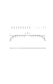
図3は、128分割された画面を示した図である。 FIG. 3 is a diagram showing a screen divided into 128 parts.
図4は、水平成分の信号の周辺光量落ち補正の様子を示した図である。 FIG. 4 is a diagram showing how the peripheral light amount drop correction is performed on the horizontal component signal.
図5は、垂直成分の信号の周辺光量落ち補正の様子を示した図である。 FIG. 5 is a diagram showing how the peripheral light amount drop correction is performed on the vertical component signal.
有効画面内を例えば、図3に示したように、垂直8画素、水平16画素、合わせて、128画素に分割し、水平成分、垂直成分、それぞれで周辺光量落ち量を算出する。 For example, as shown in FIG. 3, the effective screen is divided into 128 pixels in total of 8 vertical pixels and 16 horizontal pixels, and the amount of peripheral light loss is calculated for each of the horizontal and vertical components.
水平成分の周辺光量落ち補正は、図4に示したように、16分割した水平成分の中心2ブロックで、輝度平均値を算出する(A)。 As shown in FIG. 4, in the horizontal component peripheral light amount drop correction, a luminance average value is calculated for two central blocks of 16 horizontal components (A).
算出されたAを用いて、他の分割されたブロックの輝度値と比較し、それぞれのブロックと中心輝度の輝度差を算出する(a−A,b−A,c−A,d−A,e−A,f−A,g−A,h−A,I−A,j−A,k−A,l−A,m−A,n−A)。そして、算出された各ブロックと中心輝度との輝度差を補正するための補正ゲイン量を用いて、水平成分の信号の周辺光量落ち補正を行う。 Using the calculated A, it compares with the luminance value of the other divided blocks, and calculates the luminance difference between each block and the central luminance (a-A, b-A, c-A, d-A, e-A, f-A, g-A, h-A, IA, j-A, k-A, l-A, m-A, n-A). Then, the peripheral light amount drop correction of the horizontal component signal is performed using the correction gain amount for correcting the calculated luminance difference between each block and the central luminance.
補正された水平成分の信号を水平成分補正量制限回路106に出力し、例えば、a−Aが予め備えた基準値以上であるか否かの判定を行い、基準値以上であれば、基準値を用いて周辺光量落ち補正を行う。
The corrected horizontal component signal is output to the horizontal component correction
このように基準値以上の補正を行なわないことで、画面周辺部のS/N劣化を防止する。 Thus, S / N deterioration of the peripheral portion of the screen is prevented by not performing correction beyond the reference value.
水平成分の信号の周辺光量落ち補正と同様に、図5に示したように、8分割した垂直成分の中心2ブロックで、輝度平均値を算出する(B)。 As in the case of the peripheral light amount drop correction for the horizontal component signal, as shown in FIG. 5, the luminance average value is calculated with the two central blocks of the vertical component divided into eight (B).
算出されたBを用いて、他の分割されたブロックの輝度値と比較し、それぞれのブロックと中心輝度の差を算出する(o−B,p−B,q−B,r−B,s−B,t−B)。 Using the calculated B, it compares with the luminance value of the other divided blocks, and calculates the difference between each block and the central luminance (o-B, p-B, q-B, r-B, s -B, t-B).
そして、算出された各ブロックと中心輝度との輝度差を補正するための補正ゲイン量を用いて、垂直成分の信号の周辺光量落ち補正を行う。 Then, the peripheral light amount drop correction of the vertical component signal is performed using the correction gain amount for correcting the calculated luminance difference between each block and the central luminance.
補正された垂直成分の信号を垂直成分補正量制限回路107に出力し、例えば、o−Bが予め備えた基準値以上であるか否かの判定を行い、基準値以上であれば、基準値を用いて周辺光量落ち補正を行う。
The corrected vertical component signal is output to the vertical component correction
このように基準値以上の補正を行なわないことで、画面周辺部のS/N劣化を防止する。 Thus, S / N deterioration of the peripheral portion of the screen is prevented by not performing correction beyond the reference value.
次に、周辺光量落ち補正を行なう際の、タイミング判定動作について図6を用いて説明する。 Next, a timing determination operation when the peripheral light amount drop correction is performed will be described with reference to FIG.
図6は、絞り値の状態を判定するためのCPU9内部の回路についての構成図である。 FIG. 6 is a block diagram of a circuit inside the CPU 9 for determining the state of the aperture value.
109は、カメラ信号処理回路7から出力され、輝度レベル検波部8を介して入力された信号(Y信号)から露出値Evを算出する露出値算出回路である。
An exposure
110は、予め備えた露出制御用の制御プログラムと算出された露出値Evに基づき、現在制御されている撮像装置の制御パラメータが絞り値であるか否かを判定するパラメータ判定回路である。
111は、予め備えた露出制御用の制御プログラムと算出された露出値Evに基づき、現在の撮像装置の各種制御パラメータ(絞り値、シャッタースピード値、感度等)の値を出力する露出状態出力回路である。 Reference numeral 111 denotes an exposure state output circuit that outputs values of various control parameters (aperture value, shutter speed value, sensitivity, etc.) of the current image pickup device based on a control program for exposure control provided in advance and the calculated exposure value Ev. It is.
パラメータ判定回路110が、現在絞りを制御することで露出制御を行っていると判定した場合には、絞り制御テーブル112に、現在の絞り制御パラメータ等を出力する。
If the
なお、絞り制御テーブル112は、現在の制御パラメータの他に、絞り値が安定状態であるか否かの情報と、安定状態であった場合に安定状態になってからどれくらいの時間が経過しているかという情報も受け取ることになる。 In addition to the current control parameters, the aperture control table 112 includes information on whether or not the aperture value is in a stable state, and how much time has elapsed since the stable state in the stable state. You will also receive information about whether or not.
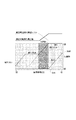
図7に上記した露出制御用の制御プログラムの一例を示す。 FIG. 7 shows an example of the control program for exposure control described above.
図7においては、簡単に表現するために、絞りと感度との関係のみを示している。斜め線になっているところが、現在制御されている制御パラメータを示している。 In FIG. 7, only the relationship between the aperture and the sensitivity is shown for simple representation. The diagonal line indicates the control parameter currently being controlled.
つまり、絞り値がF1.8より小さく(明るく)なると、絞りの制御は行われず、感度を上げる制御をすることで露出値Evを制御している。 That is, when the aperture value is smaller (brighter) than F1.8, the aperture value is not controlled, and the exposure value Ev is controlled by controlling the sensitivity.
そして、図7において、比較的小絞り側では周辺光量落ちの影響は見受けられないが、網掛け部分のエリアにおいて絞りが制御されている間は周辺光量落ちの影響が顕著になることを示している。 FIG. 7 shows that the effect of a decrease in the amount of peripheral light is not observed on the relatively small aperture side, but the effect of the decrease in the amount of peripheral light is significant while the aperture is controlled in the shaded area. Yes.
116は予め設定された基準値と絞り制御テーブル112からの出力信号から算出した絞り値の安定時間とを比較することにより、絞り値が安定状態であるか否かを判定する、絞り安定度判定回路であり、第1の判定手段の一例である。
A diaphragm
なお、絞り値の安定時間とは、絞り値の変化量が予め定められた範囲内にある場合を安定状態とみなし、安定状態とみなされている時間を計測することで得られる時間のことである。 The aperture value stabilization time is the time obtained by measuring the time when the aperture value change amount is within a predetermined range as the stable state and measuring the time considered as the stable state. is there.
絞り値が安定状態であると判定された場合には、周辺光量補正回路6に、周辺光量落ち補正ON信号を出力する。 When it is determined that the aperture value is in a stable state, a peripheral light amount drop correction ON signal is output to the peripheral light amount correction circuit 6.
絞り安定度判定回路116にて、絞り値が安定状態でないと判定された場合、つまり絞り値が変動状態であると判定されると、周辺光量補正回路6に周辺光量落ち補正OFF信号を出力する。
If the aperture
絞り値の安定状態を判定する理由は、絞り値が安定していない、即ち絞り値が変動していると、周辺光量補正を行っても、適切な補正の効果が出ない、或いは間違った補正を行ってしまうことがあるからである。そのため本発明では、絞り値の安定時間が所定時間を越えた場合に、安定している(変動していない)とみなして、補正を行うようにしている。 The reason for determining the stable state of the aperture value is that the aperture value is not stable, that is, if the aperture value fluctuates, even if the peripheral light amount correction is performed, the effect of the appropriate correction does not appear, or incorrect correction This is because there is a case where it is done. For this reason, in the present invention, when the aperture value stabilization time exceeds a predetermined time, it is assumed that the aperture value is stable (not fluctuated) and correction is performed.
同様に、パラメータ判定回路110は、ND制御テーブル113と、シャッター制御テーブル114と、AGC制御テーブル115にも、それぞれの現在の制御パラメータ等を出力する。
Similarly, the
そして、ND制御テーブル113、シャッター制御テーブル114、AGC制御テーブル115は、入力された各種制御パラメータを制御パラメータに対応する制御値にそれぞれ変換して、レンズ1、固体撮像素子3、AFE4にそれぞれ出力する。
The ND control table 113, the shutter control table 114, and the AGC control table 115 convert various input control parameters into control values corresponding to the control parameters, respectively, and output them to the
また、パラメータ判定回路110が、現在絞り以外を制御することで露出制御を行っていると判定した場合には、絞り制御テーブル112に、現在の絞り制御パラメータ等を出力する。
If the
そして、絞り安定度判定回路116にて判定を行わずに、直接、周辺光量補正回路6に周辺光量落ち補正ON信号を出力する。
Then, without making a determination in the diaphragm
これは、パラメータ判定回路110が、現在絞り以外を制御することで露出制御を行っていると判定しているので、絞り値は当然安定している(絞り値の変動はない)ものとみなせるからである。
This is because the
しかし、絞り安定度判定回路116にて絞り安定度の判定を行ってから(当然安定しているとみなされるが)、周辺光量補正回路6に信号を送るようにしても良い。
However, a signal may be sent to the peripheral light amount correction circuit 6 after the diaphragm
同様に、パラメータ判定回路110は、ND制御テーブル113と、シャッター制御テーブル114と、AGC制御テーブル115にも、それぞれの現在の制御パラメータ等を出力する。
Similarly, the
そして、ND制御テーブル113、シャッター制御テーブル114、AGC制御テーブル115は、入力された各種制御パラメータを制御パラメータに対応する制御値にそれぞれ変換して、レンズ1、固体撮像素子3、AFE4にそれぞれ出力する。
The ND control table 113, the shutter control table 114, and the AGC control table 115 convert various input control parameters into control values corresponding to the control parameters, respectively, and output them to the
次に、周辺光量落ち補正の動作フローについて、図8を用いて説明する。 Next, the operation flow of the peripheral light amount drop correction will be described with reference to FIG.
図8は、周辺光量落ち補正の動作フローチャートである。 FIG. 8 is an operation flowchart of the peripheral light amount drop correction.
ステップS100にて、撮影者が被写体撮影を開始する。 In step S100, the photographer starts photographing the subject.
ステップS101にて、CPU9は、被写体撮影中の現在の絞り値を取得する。なお、撮像素子に光信号(被写体像)が入力されている間は、絞り制御テーブル112は、リアルタイムの絞り値(制御値)を常時出力することが可能に構成されているものとする。 In step S101, the CPU 9 acquires the current aperture value during shooting of the subject. It is assumed that the aperture control table 112 is configured to always output a real-time aperture value (control value) while an optical signal (subject image) is input to the image sensor.
ステップS102にて、CPU9は、ステップS101で取得した現在の絞り値における、被写体撮影中の絞り値の安定時間の計測を開始する。 In step S102, the CPU 9 starts measuring the stable time of the aperture value during subject shooting at the current aperture value acquired in step S101.
ステップS103にて、CPU9は、ステップS102で計測された絞り値の安定時間と予め設定された基準値(例えば50V)とを比較する。 In step S103, the CPU 9 compares the stabilization time of the aperture value measured in step S102 with a preset reference value (for example, 50V).
ステップS103での比較の結果、絞り値の安定時間が50Vより小さいと判定された場合は、絞り値が安定していないとみなし、CPU9は処理をステップS110に進める。そして、CPU9は、周辺光量落ち補正動作は行わないという指令を周辺光量補正回路6へ送る。なお、絞りが駆動している、つまり安定状態でない時に、周辺光量落ち補正を行わない状態を第2の状態の一例とする。 As a result of the comparison in step S103, if it is determined that the aperture value stabilization time is less than 50V, the aperture value is regarded as not stable, and the CPU 9 advances the process to step S110. Then, the CPU 9 sends to the peripheral light amount correction circuit 6 a command not to perform the peripheral light amount drop correction operation. Note that a state where the peripheral light amount drop correction is not performed when the diaphragm is driven, that is, not in a stable state, is an example of the second state.
ステップS103での比較の結果、絞り値の安定時間が50V以上であると判定された場合は、絞り値が安定しているとみなし、CPU9は処理をステップS104に進める。 As a result of the comparison in step S103, if it is determined that the aperture value stabilization time is 50 V or more, the CPU 9 regards the aperture value as stable, and the CPU 9 advances the process to step S104.
ステップS104では、CPU9は、現状の絞り値に対する周辺光量落ち補正データをメモリ10から取得する。 In step S <b> 104, the CPU 9 acquires peripheral light amount drop correction data for the current aperture value from the memory 10.
ステップS105では、CPU9は、ステップS104にて取得した周辺光量落ち補正データを周辺光量補正回路6に転送し、周辺光量補正回路6は周辺光量落ち補正を行う。なお、絞りが駆動していない、つまり安定状態である時に、周辺光量落ち補正を行っている状態を第1の状態の一例とする。 In step S105, the CPU 9 transfers the peripheral light amount correction data acquired in step S104 to the peripheral light amount correction circuit 6, and the peripheral light amount correction circuit 6 performs peripheral light amount correction. Note that a state in which the peripheral light amount drop correction is performed when the diaphragm is not driven, that is, in a stable state is an example of the first state.
ステップS106では、CPU9は、現在の絞り値を取得する。 In step S106, the CPU 9 acquires the current aperture value.
ステップS107では、ステップS101で取得した絞り値とステップS106にて取得した絞り値とを比較して変化があるか否かの判定を行う。 In step S107, the aperture value acquired in step S101 is compared with the aperture value acquired in step S106 to determine whether there is a change.
絞り値の比較の結果、絞り値の差が予め定められた設定値以上であれば変化したとみなし、絞り値の差が予め定められた設定値より小さい場合には変化してないとみなす。 As a result of the comparison of the aperture values, if the aperture value difference is equal to or larger than a predetermined set value, it is considered that the aperture value has changed. If the aperture value difference is smaller than the predetermined set value, it is regarded that the aperture value has not changed.
ステップS107にて、絞り値に変化があった場合には、ステップS109にて周辺光量補正回路6は、動作している周辺光量落ち補正の動作を停止し、ステップS102に戻り、絞り値の安定時間の計測を開始する。 If there is a change in the aperture value in step S107, the peripheral light amount correction circuit 6 stops the operation of correcting the peripheral light amount drop in operation in step S109, and returns to step S102 to stabilize the aperture value. Start measuring time.
ステップS107にて、絞り値に変化がなかった場合には、ステップS108にて周辺光量補正回路6は、周辺光量落ち補正の動作を継続する。そして、所定時間経過したらステップS106からの処理を繰り返す。 If the aperture value has not changed in step S107, the peripheral light amount correction circuit 6 continues the peripheral light amount drop correction operation in step S108. When the predetermined time has elapsed, the processing from step S106 is repeated.
以上説明したように、本発明の第1の実施形態によれば、被写体撮影中の絞り値の安定状態を判定して、周辺光量落ち補正のON/OFF切替を行なっている。そうすることで、周辺光量落ち補正の過不足を防止し、安定的な周辺光量落ち補正を行うことを可能にしている。 As described above, according to the first embodiment of the present invention, the stable state of the aperture value during shooting of the subject is determined, and ON / OFF switching of the peripheral light amount drop correction is performed. By doing so, it is possible to prevent excessive and insufficient peripheral light amount drop correction and to perform stable peripheral light amount drop correction.
なお、本実施形態においては、絞り値が安定していないと判定されると、それ以降周辺光量落ち補正を行わない処理フローになっているが、それに限られるわけではない。 In the present embodiment, when it is determined that the aperture value is not stable, the processing flow in which the peripheral light amount drop correction is not performed thereafter is not limited thereto.
周辺光量落ち補正動作は行わないという指令が周辺光量補正回路6へ送られてから、所定時間経過後、再び絞り値の安定時間を計測し、安定していれば周辺光量落ち補正を行うことにしてもよい。 After a command that the peripheral light amount drop correction operation is not performed is sent to the peripheral light amount correction circuit 6, after a predetermined time has passed, the stabilization time of the aperture value is measured again, and if it is stable, the peripheral light amount drop correction is performed. May be.
なお、本実施形態では、絞り値の変化が所定範囲内にある場合を安定状態とみなしているが、安定状態とみなすための変化量を絞りが開放側から小絞り側に変化する際と、小絞り側から開放側に変化する際とで変えても良い。 In the present embodiment, the case where the change in the aperture value is within a predetermined range is regarded as a stable state, but when the aperture changes from the open side to the small aperture side, the amount of change to be regarded as a stable state, It may be changed when changing from the small aperture side to the open side.
具体的には、開放側から小絞り側へ変化する際には、過補正になるので、安定状態とみなす絞り値の変化量を、補正不足になる小絞り側から開放側へ変化する際より小さく設定する。 Specifically, over-correction occurs when changing from the open side to the small-aperture side, so the amount of change in the aperture value that is regarded as a stable state is greater than when changing from the small-aperture side, which is under-corrected, to the open side. Set smaller.
これは、補正不足と異なり、過補正は補正をやりすぎ画質を極端に落とすことが考えられるからである。
また、本実施形態において、第2の状態の時には、補正を行わないとしているが、第1の状態の時に比べて弱めの補正をかけるようにしてもよい。絞りが安定状態にない状態の時にも、このように過補正にならない程度に補正をかけることで、補正を全くかけていない状態よりも画像の質を向上させることができる。
This is because unlike overcorrection, overcorrection can be overcorrected and the image quality can be drastically reduced.
In the present embodiment, correction is not performed in the second state, but weak correction may be applied as compared to the first state. Even when the aperture is not in a stable state, the image quality can be improved as compared with a state in which no correction is performed by performing correction to such an extent that over-correction is not performed.
<第2の実施形態>
以下、本発明の第2の実施形態について説明する。なお、撮像装置の構成について第1の実施形態と同様の構成については説明を割愛する。
<Second Embodiment>
Hereinafter, a second embodiment of the present invention will be described. In addition, about the structure of an imaging device, the structure similar to 1st Embodiment is abbreviate | omitted description.
続いて本第2の実施形態における撮像装置の構成について図9を用いて説明する。 Next, the configuration of the imaging apparatus according to the second embodiment will be described with reference to FIG.
本実施形態では防振振り角(シフト量)が所定の基準値より大きいか否かで、周辺光量落ち補正を行うか否かを判定している。これは、防振振り角が基準値より大きい、つまり、光軸の位置の変化が大きい場合は、周辺光量補正を行っても適切な補正の効果が出ない、或いは間違った補正を行ってしまうことがあるからである。 In the present embodiment, it is determined whether or not the peripheral light amount drop correction is performed based on whether or not the image stabilization swing angle (shift amount) is larger than a predetermined reference value. This is because if the image stabilization swing angle is larger than the reference value, that is, if the change in the position of the optical axis is large, even if the peripheral light amount correction is performed, the effect of the appropriate correction is not obtained, or incorrect correction is performed. Because there are things.
そのため本発明では、防振振り角が所定の基準値以下の場合に、補正を行うようにしている。 Therefore, in the present invention, correction is performed when the image stabilization swing angle is equal to or smaller than a predetermined reference value.
図9は、撮像装置が備えるレンズ内部に備えた防振機能を具備した撮像装置のブロック図である。なお、防振機能とは、被写体撮影中のユーザーの手ぶれによって発生する画像のぶれを補正するための手段である(これより、防振機能という)。 FIG. 9 is a block diagram of an imaging apparatus having an image stabilization function provided in a lens included in the imaging apparatus. Note that the image stabilization function is a means for correcting image blur caused by a user's camera shake during subject shooting (hereinafter referred to as an image stabilization function).
同図において、14はレンズ1の後段に備えられ、CPU9からの制御信号に応じて画像のぶれを補正するためにレンズ位置を変動させるレンズシフト部である。
In the figure, reference numeral 14 denotes a lens shift unit which is provided in the rear stage of the
15は画像のぶれの補正量を算出するために、撮像装置内に備えたレンズの位置情報を検出し、そのレンズの位置情報をCPU9に出力するレンズ位置検出部である。 Reference numeral 15 denotes a lens position detection unit that detects position information of a lens provided in the imaging apparatus and outputs the position information of the lens to the CPU 9 in order to calculate a correction amount of image blur.
CPU9では、レンズの位置情報に基づき、画像のぶれ量を算出し防振補正角を算出する。 The CPU 9 calculates the image blur amount and the image stabilization angle based on the lens position information.
レンズシフト部14は、算出された防振補正角に基づきレンズのシフト制御を行なうことで手ぶれによる画像のブレを補正する。本発明においては、CPU9、レンズシフト部14、レンズ位置検出部15の機能により防振手段としての役割を担う。 The lens shift unit 14 corrects image blur due to camera shake by performing lens shift control based on the calculated image stabilization correction angle. In the present invention, the functions of the CPU 9, the lens shift unit 14, and the lens position detection unit 15 serve as a vibration isolating means.
また、上記では光学防振の構成について説明したが、それとは異なり、電子防振時は、固体撮像素子の有効画素の切り出し領域を変化させる。 In addition, the configuration of optical image stabilization has been described above, but unlike that, the cutout region of the effective pixel of the solid-state image sensor is changed during electronic image stabilization.
そのため、電子防振時の防振角検出は、例えば、CPU9が切り出し画素の中心のベクトル値を算出し、それぞれの画素のベクトルから、動きベクトル量を算出することで、防振角を算出する。 Therefore, for example, the CPU 9 calculates the image stabilization angle by calculating the vector value of the center of the cut-out pixel and calculating the motion vector amount from the vector of each pixel. .
次に、防振機能を具備した撮像装置における周辺光量落ち補正の動作フローについて、図10を用いて説明する。 Next, the operation flow of the peripheral light amount drop correction in the image pickup apparatus having the image stabilization function will be described with reference to FIG.
図10は、防振機能を具備した撮像装置における周辺光量落ち補正の動作フローチャートである。 FIG. 10 is an operation flowchart of the peripheral light amount drop correction in the image pickup apparatus having the image stabilization function.
本実施形態において。ステップS100からステップS102までの処理の説明については第1の実施形態と同じであるためその説明を省略する。 In this embodiment. Since the description of the processing from step S100 to step S102 is the same as that of the first embodiment, the description thereof is omitted.
ステップS103での比較の結果、絞り値の安定時間が50Vより長いと判定された場合は、絞り値が安定しているとみなし、CPU9は処理をステップS120に進める。 As a result of the comparison in step S103, when it is determined that the stable time of the aperture value is longer than 50V, the CPU 9 regards that the aperture value is stable and advances the processing to step S120.
ステップS120では、CPU9は、現在の防振振り角を取得する。 In step S120, the CPU 9 acquires the current image stabilization angle.
ステップS121では、CPU9は、ステップS120で取得した現在の防振振り角と予め設定された基準値(例えば1°)とを比較する。 In step S121, the CPU 9 compares the current image stabilization angle acquired in step S120 with a preset reference value (for example, 1 °).
ステップS121にて、防振振り角が1°より大きいと判定した場合には、CPU9は処理をステップS110に進める。そして、CPU9は、周辺光量落ち補正動作は行わないという指令を周辺光量補正回路6へ送る。このように、絞りが安定状態であっても、防振振り角が1°より大きく、絞りの駆動と防振機能の駆動のうちいずれか一方でも周辺光量落ち補正に影響を与える状態を第2の状態の一例とする。 If it is determined in step S121 that the image stabilization swing angle is greater than 1 °, the CPU 9 advances the process to step S110. Then, the CPU 9 sends to the peripheral light amount correction circuit 6 a command not to perform the peripheral light amount drop correction operation. In this way, even when the diaphragm is in a stable state, the vibration-proof swing angle is larger than 1 °, and the second state in which any one of the drive of the diaphragm and the drive of the vibration-proof function has an influence on the peripheral light amount drop correction. An example of the state is as follows.
ステップS121にて、防振振り角が1°以下であると判定した場合には、CPU9はメモリ10から周辺光量落ち補正データを取得し、処理をステップS105へ進め周辺光量落ち補正を行なう。 If it is determined in step S121 that the image stabilization swing angle is 1 ° or less, the CPU 9 acquires peripheral light amount drop correction data from the memory 10 and proceeds to step S105 to perform peripheral light amount drop correction.
このように、絞りが安定状態であり、防振振り角が1°以下であり、絞りの駆動と防振機能の駆動が共に周辺光量落ち補正に影響を与えない程度である状態を第1の状態の一例とする。 As described above, the first state is a state where the diaphragm is in a stable state, the vibration-proof swing angle is 1 ° or less, and both the drive of the diaphragm and the drive of the vibration-proof function do not affect the peripheral light amount drop correction. An example of the state.
ここで、周辺光量落ち補正量は、現在の絞り値に対応した補正量を防振振り角分だけ、水平あるいは、垂直にシフトした値とする。 Here, the peripheral light amount drop correction amount is a value obtained by shifting the correction amount corresponding to the current aperture value horizontally or vertically by an amount corresponding to the anti-vibration angle.
次に、ステップS106にて、CPU9は、現在の絞り値を取得する。 Next, in step S106, the CPU 9 acquires the current aperture value.
ステップS107では、ステップS101で取得した絞り値とステップS106にて取得した絞り値とを比較して変化があるか否かの判定を行う。 In step S107, the aperture value acquired in step S101 is compared with the aperture value acquired in step S106 to determine whether there is a change.
絞り値の比較の結果、絞り値の差が予め定められた設定値以上であれば変化したとみなし、絞り値の差が予め定められた設定値より小さい場合には変化してないとみなす。 As a result of the comparison of the aperture values, if the aperture value difference is equal to or larger than a predetermined set value, it is considered that the aperture value has changed. If the aperture value difference is smaller than the predetermined set value, it is regarded that the aperture value has not changed.
ステップS107にて、絞り値に変化があった場合には、ステップS109にて周辺光量補正回路6は、動作している周辺光量落ち補正の動作を停止し、ステップS102に戻り、絞り値の安定時間の計測を開始する。 If there is a change in the aperture value in step S107, the peripheral light amount correction circuit 6 stops the operation of correcting the peripheral light amount drop in operation in step S109, and returns to step S102 to stabilize the aperture value. Start measuring time.
ステップS107にて、絞り値に変化がなかった場合には、ステップS122にてCPU9は、現在の防振振り角を取得する。 If there is no change in the aperture value in step S107, the CPU 9 acquires the current image stabilization angle in step S122.
そして、ステップS123にて、CPU9は、ステップS122で取得した現在の防振振り角と予め設定された基準値(例えば1°)とを比較する。 In step S123, the CPU 9 compares the current image stabilization angle acquired in step S122 with a preset reference value (for example, 1 °).
ステップS123にて、防振振り角が1°より大きいと判定した場合には、CPU9は処理をステップS109に進める。そして、ステップS109にて周辺光量補正回路6は、動作している周辺光量落ち補正の動作を停止し、ステップS102に戻り、絞り値の安定時間の計測を開始する。 If it is determined in step S123 that the image stabilization swing angle is greater than 1 °, the CPU 9 advances the process to step S109. Then, in step S109, the peripheral light amount correction circuit 6 stops the operation of correcting the peripheral light amount decrease, returns to step S102, and starts measuring the aperture value stabilization time.
ステップS123にて、防振振り角が1°以下であると判定した場合には、ステップS108にて周辺光量補正回路6は、周辺光量落ち補正の動作を継続する。そして、所定時間経過したらステップS106からの処理を繰り返す。 If it is determined in step S123 that the image stabilization swing angle is 1 ° or less, the peripheral light amount correction circuit 6 continues the peripheral light amount drop correction operation in step S108. When the predetermined time has elapsed, the processing from step S106 is repeated.
以上説明したように、本発明の第2の実施形態によれば、絞り値の変化に加え、防振振り角の変化も加味して、周辺光量落ち補正のON/OFF切替を行なっている。そうすることで、撮像装置に防振機能が具備された場合でも、周辺光量落ち補正の過不足を防止し、安定的な周辺光量落ち補正を行うことを可能にしている。 As described above, according to the second embodiment of the present invention, the ON / OFF switching of the peripheral light amount drop correction is performed in consideration of the change in the vibration reduction angle in addition to the change in the aperture value. By doing so, even when the image pickup apparatus is provided with an anti-vibration function, it is possible to prevent excessive and insufficient peripheral light amount drop correction and to perform stable peripheral light amount drop correction.
なお、本実施形態においては、絞り値の変化があるか否かの判定を行ってから、防振振り角の変化の判定を行っているが、先に防振振り角の変化の判定を行っても問題はない。 In this embodiment, after determining whether or not there is a change in the aperture value, the change in the image stabilization swing angle is determined. However, the change in the image stabilization swing angle is determined first. There is no problem.
また、絞り値の変化の判定と防振振り角の変化の判定を並行に行い、それぞれの判定結果を加味して周辺光量落ち補正を行うか否かの判断をしてもよい。 Further, the determination of the change in the aperture value and the determination of the change in the vibration proof swing angle may be performed in parallel, and it may be determined whether or not the peripheral light amount drop correction is performed in consideration of the respective determination results.
1 レンズ
2 絞り
3 固体撮像素子
4 AFE
5 TG
6 周辺光量補正回路
7 カメラ信号処理回路
8 輝度レベル検波部
9 CPU
10 メモリ
11 ビデオ信号処理回路
12 記録部
13 モニター
14 レンズシフト部
15 レンズ位置検出部
100 画面分割回路
101 水平/垂直成分分離回路
102 水平成分補正中心検出回路
103 垂直成分補正中心検出回路
104 水平成分周辺光量補正回路
105 垂直成分周辺光量補正回路
106 水平成分補正量制限回路
107 垂直成分補正量制限回路
108 合成回路
109 露出値算出回路
110 パラメータ判定回路
111 露出状態出力回路
112 絞り制御テーブル
113 ND制御テーブル
114 シャッター制御テーブル
115 AGC制御テーブル
116 絞り安定度判定回路
DESCRIPTION OF
5 TG
6 Peripheral light amount correction circuit 7 Camera signal processing circuit 8 Luminance level detection unit 9 CPU
DESCRIPTION OF SYMBOLS 10 Memory 11 Video signal processing circuit 12
Claims (9)
開口径を変化させて前記撮像手段の撮像面への入射光量を調整する絞り手段と、
前記撮像手段により取得した画像データに対して周辺光量落ち補正を行う補正手段と、
を有し、
前記補正手段は、前記絞り手段の開口径を所定値以上の変化量で変化させている際に取得した画像データに対してよりも、前記開口径を前記所定値以上の変化量で変化させていない際に取得した画像データに対して強く前記周辺光量落ち補正を行い、前記開口径を小絞り側に変化させるときは前記開口径を開放側に変化させるときよりも前記所定値を小さくすることを特徴とする撮像装置。 Imaging means for capturing an image of a subject and acquiring image data;
A diaphragm unit that adjusts the amount of light incident on the imaging surface of the imaging unit by changing an aperture diameter;
Correction means for performing peripheral light amount drop correction on the image data acquired by the imaging means;
Have
Said correction means, said aperture than the opening diameter on the image data obtained when the is varied by a predetermined value or more variation means, have the aperture diameter is changed by a change amount of the predetermined value or more There line the peripheral light amount drop correction strongly on the acquired image data when no time for changing the aperture diameter on the small aperture side is smaller the predetermined value than when changing the opening diameter on the open side An imaging apparatus characterized by that.
開口径を変化させて前記撮像手段の撮像面への入射光量を調整する絞り手段と、
画像のぶれを補正するぶれ補正手段と、
前記撮像手段により取得した画像データに対して周辺光量落ち補正を行う補正手段と、
を有し、
前記補正手段は、前記絞り手段の開口径を第1の所定値以上の変化量で変化させている際に取得した画像データに対してよりも、前記開口径を前記第1の所定値以上の変化量で変化させていなくて前記ぶれ補正手段により第2の所定値以上の補正量でぶれ補正を行っていない際に取得した画像データに対して強く前記周辺光量落ち補正を行うことを特徴とする撮像装置。 Imaging means for capturing an image of a subject and acquiring image data;
A diaphragm unit that adjusts the amount of light incident on the imaging surface of the imaging unit by changing an aperture diameter;
Image stabilization means for correcting image blur ;
Correction means for performing peripheral light amount drop correction on the image data acquired by the imaging means;
Have,
The correction means has the opening diameter larger than the first predetermined value than the image data acquired when the opening diameter of the diaphragm means is changed by a change amount not smaller than the first predetermined value. The marginal light amount drop correction is strongly performed on image data acquired when the blur correction unit does not perform blur correction with a correction amount equal to or greater than a second predetermined value without being changed by a change amount. An imaging device.
前記撮像手段により取得した画像データに対して周辺光量落ち補正を行う補正ステップを有し、
前記補正ステップは、前記絞り手段の開口径を所定値以上の変化量で変化させている際に取得した画像データに対してよりも、前記開口径を前記所定値以上の変化量で変化させていない際に取得した画像データに対して強く前記周辺光量落ち補正を行い、前記開口径を小絞り側に変化させるときは前記開口径を開放側に変化させるときよりも前記所定値を小さくすることを特徴とする撮像装置の制御方法。 An imaging apparatus control method comprising: an imaging unit that captures an image of a subject to acquire image data; and an aperture unit that changes an aperture diameter to adjust an amount of light incident on an imaging surface of the imaging unit.
A correction step of performing peripheral light amount drop correction on the image data acquired by the imaging means;
Said correction step, said aperture than the opening diameter on the image data obtained when the is varied by a predetermined value or more variation means, have the aperture diameter is changed by a change amount of the predetermined value or more There line the peripheral light amount drop correction strongly on the acquired image data when no time for changing the aperture diameter on the small aperture side is smaller the predetermined value than when changing the opening diameter on the open side And a method of controlling the imaging apparatus.
前記撮像手段により取得した画像データに対して周辺光量落ち補正を行う補正ステップを有し、A correction step of performing peripheral light amount drop correction on the image data acquired by the imaging means;
前記補正ステップは、前記絞り手段の開口径を第1の所定値以上の変化量で変化させている際に取得した画像データに対してよりも、前記開口径を前記第1の所定値以上の変化量で変化させていなくて前記ぶれ補正手段により第2の所定値以上の補正量でぶれ補正を行っていない際に取得した画像データに対して強く前記周辺光量落ち補正を行うことを特徴とする撮像装置の制御方法。In the correcting step, the aperture diameter is set to be equal to or larger than the first predetermined value than to the image data acquired when the aperture diameter of the aperture means is changed by a change amount equal to or larger than the first predetermined value. The marginal light amount drop correction is strongly performed on image data acquired when the blur correction unit does not perform blur correction with a correction amount equal to or greater than a second predetermined value without being changed by a change amount. Control method for imaging apparatus.
Priority Applications (2)
| Application Number | Priority Date | Filing Date | Title |
|---|---|---|---|
| JP2007133888A JP4958635B2 (en) | 2007-05-21 | 2007-05-21 | Imaging apparatus and control method thereof |
| US12/107,673 US7982773B2 (en) | 2007-05-21 | 2008-04-22 | Imaging apparatus capable of capturing an image with reduced light falloff at edges and method for controlling the same |
Applications Claiming Priority (1)
| Application Number | Priority Date | Filing Date | Title |
|---|---|---|---|
| JP2007133888A JP4958635B2 (en) | 2007-05-21 | 2007-05-21 | Imaging apparatus and control method thereof |
Publications (3)
| Publication Number | Publication Date |
|---|---|
| JP2008289036A JP2008289036A (en) | 2008-11-27 |
| JP2008289036A5 JP2008289036A5 (en) | 2010-06-24 |
| JP4958635B2 true JP4958635B2 (en) | 2012-06-20 |
Family
ID=40072018
Family Applications (1)
| Application Number | Title | Priority Date | Filing Date |
|---|---|---|---|
| JP2007133888A Expired - Fee Related JP4958635B2 (en) | 2007-05-21 | 2007-05-21 | Imaging apparatus and control method thereof |
Country Status (2)
| Country | Link |
|---|---|
| US (1) | US7982773B2 (en) |
| JP (1) | JP4958635B2 (en) |
Families Citing this family (7)
| Publication number | Priority date | Publication date | Assignee | Title |
|---|---|---|---|---|
| JP2008058445A (en) * | 2006-08-30 | 2008-03-13 | Canon Inc | Lens drive device, image blur correction device, and imaging apparatus |
| US8314865B2 (en) * | 2009-12-23 | 2012-11-20 | Nokia Corporation | Lens shading correction |
| US8547440B2 (en) * | 2010-01-29 | 2013-10-01 | Nokia Corporation | Image correction for image capturing with an optical image stabilizer |
| JP4922440B2 (en) * | 2010-07-08 | 2012-04-25 | 株式会社東芝 | 3D video output device, 3D video display device, 3D video output method |
| JP2015144327A (en) * | 2014-01-31 | 2015-08-06 | 株式会社 日立産業制御ソリューションズ | imaging device |
| JP6795961B2 (en) * | 2016-12-12 | 2020-12-02 | キヤノン株式会社 | Image processing device, control method of image processing device, and program |
| CN111381414B (en) * | 2018-12-29 | 2021-11-30 | 武汉华星光电半导体显示技术有限公司 | Optical compensation method and device for OLED (organic light emitting diode) under-screen camera |
Family Cites Families (11)
| Publication number | Priority date | Publication date | Assignee | Title |
|---|---|---|---|---|
| JPH0955886A (en) * | 1995-08-11 | 1997-02-25 | Canon Inc | Image pickup device |
| US20040201707A1 (en) * | 1998-03-12 | 2004-10-14 | Kazuhiro Noguchi | Variable magnification lens having image stabilizing function |
| JP3591357B2 (en) * | 1999-02-10 | 2004-11-17 | 松下電器産業株式会社 | Image motion compensation device |
| JP3854754B2 (en) * | 1999-06-30 | 2006-12-06 | キヤノン株式会社 | Imaging apparatus, image processing apparatus and method, and memory medium |
| JP4724287B2 (en) * | 2000-10-26 | 2011-07-13 | キヤノン株式会社 | camera |
| JP2003110936A (en) | 2001-09-27 | 2003-04-11 | Matsushita Electric Ind Co Ltd | Image pickup device |
| JP2004317650A (en) * | 2003-04-14 | 2004-11-11 | Fuji Photo Film Co Ltd | Camera |
| JP2006165784A (en) | 2004-12-03 | 2006-06-22 | Canon Inc | Image pickup device |
| JP4980024B2 (en) * | 2005-10-07 | 2012-07-18 | Hoya株式会社 | Image blur correction device |
| JP2007114311A (en) * | 2005-10-18 | 2007-05-10 | Pentax Corp | Image blur correction device and image blur correction method for imaging apparatus |
| JP4536641B2 (en) * | 2005-11-02 | 2010-09-01 | ルネサスエレクトロニクス株式会社 | Image blur correction apparatus, image blur correction method, and image blur correction program |
-
2007
- 2007-05-21 JP JP2007133888A patent/JP4958635B2/en not_active Expired - Fee Related
-
2008
- 2008-04-22 US US12/107,673 patent/US7982773B2/en not_active Expired - Fee Related
Also Published As
| Publication number | Publication date |
|---|---|
| JP2008289036A (en) | 2008-11-27 |
| US7982773B2 (en) | 2011-07-19 |
| US20080291299A1 (en) | 2008-11-27 |
Similar Documents
| Publication | Publication Date | Title |
|---|---|---|
| JP4594257B2 (en) | Digital imaging device | |
| JP5347707B2 (en) | Imaging apparatus and imaging method | |
| WO2015151386A1 (en) | Image-capturing device, method for outputting image data, and program | |
| JP4958635B2 (en) | Imaging apparatus and control method thereof | |
| JP2009201094A (en) | Imaging apparatus and imaging method | |
| JP2010074313A (en) | Imaging apparatus and method for controlling the same | |
| JP5780764B2 (en) | Imaging device | |
| JP5223686B2 (en) | Imaging apparatus and imaging method | |
| JP2006262220A (en) | Imaging apparatus | |
| JP2010178164A (en) | Imaging apparatus | |
| JP2008209577A (en) | Camera | |
| US9420223B2 (en) | Image recording device that records moving image, method of controlling the same, and storage medium | |
| JP5948997B2 (en) | Imaging apparatus and imaging method | |
| US7619681B2 (en) | Image-capturing device that, when it is determined that a control value of an exposure-control exceeds a corresponding predetermined value, adjusts the control value to a value not exceeding the corresponding predetermined value, then sets the control value again based on the result of comparing luminance data obtained after an adjustment and a predetermined target luminance value, and method for controlling same | |
| JP2010068046A (en) | Imaging apparatus | |
| JP2010103700A (en) | Imaging device and imaging method | |
| JP5003348B2 (en) | Electronic camera | |
| JP2006253970A (en) | Imaging apparatus, shading correction data generating method, and program | |
| JP2012134745A (en) | Image signal processing device | |
| JP2004328606A (en) | Imaging device | |
| JP2010093780A (en) | Imaging apparatus and imaging method | |
| JP2006013731A (en) | Imaging device, white balance control method, and device for adjusting quantity of light | |
| JP2010271507A (en) | Imaging device, exposure adjustment method, and program | |
| JP4415196B2 (en) | Imaging apparatus and imaging method | |
| JP2009188879A (en) | Digital camera |
Legal Events
| Date | Code | Title | Description |
|---|---|---|---|
| RD04 | Notification of resignation of power of attorney |
Free format text: JAPANESE INTERMEDIATE CODE: A7424 Effective date: 20100201 |
|
| A521 | Request for written amendment filed |
Free format text: JAPANESE INTERMEDIATE CODE: A523 Effective date: 20100511 |
|
| A621 | Written request for application examination |
Free format text: JAPANESE INTERMEDIATE CODE: A621 Effective date: 20100511 |
|
| RD01 | Notification of change of attorney |
Free format text: JAPANESE INTERMEDIATE CODE: A7421 Effective date: 20100630 |
|
| A977 | Report on retrieval |
Free format text: JAPANESE INTERMEDIATE CODE: A971007 Effective date: 20111101 |
|
| A131 | Notification of reasons for refusal |
Free format text: JAPANESE INTERMEDIATE CODE: A131 Effective date: 20111122 |
|
| A521 | Request for written amendment filed |
Free format text: JAPANESE INTERMEDIATE CODE: A523 Effective date: 20120120 |
|
| TRDD | Decision of grant or rejection written | ||
| A01 | Written decision to grant a patent or to grant a registration (utility model) |
Free format text: JAPANESE INTERMEDIATE CODE: A01 Effective date: 20120221 |
|
| A01 | Written decision to grant a patent or to grant a registration (utility model) |
Free format text: JAPANESE INTERMEDIATE CODE: A01 |
|
| A61 | First payment of annual fees (during grant procedure) |
Free format text: JAPANESE INTERMEDIATE CODE: A61 Effective date: 20120319 |
|
| FPAY | Renewal fee payment (event date is renewal date of database) |
Free format text: PAYMENT UNTIL: 20150330 Year of fee payment: 3 |
|
| R151 | Written notification of patent or utility model registration |
Ref document number: 4958635 Country of ref document: JP Free format text: JAPANESE INTERMEDIATE CODE: R151 |
|
| LAPS | Cancellation because of no payment of annual fees |