JP4958599B2 - Head-mounted video display device - Google Patents
Head-mounted video display device Download PDFInfo
- Publication number
- JP4958599B2 JP4958599B2 JP2007089044A JP2007089044A JP4958599B2 JP 4958599 B2 JP4958599 B2 JP 4958599B2 JP 2007089044 A JP2007089044 A JP 2007089044A JP 2007089044 A JP2007089044 A JP 2007089044A JP 4958599 B2 JP4958599 B2 JP 4958599B2
- Authority
- JP
- Japan
- Prior art keywords
- observer
- head
- occipital
- display device
- arm
- Prior art date
- Legal status (The legal status is an assumption and is not a legal conclusion. Google has not performed a legal analysis and makes no representation as to the accuracy of the status listed.)
- Expired - Fee Related
Links
Images


Classifications
-
- G—PHYSICS
- G02—OPTICS
- G02B—OPTICAL ELEMENTS, SYSTEMS OR APPARATUS
- G02B27/00—Optical systems or apparatus not provided for by any of the groups G02B1/00 - G02B26/00, G02B30/00
- G02B27/01—Head-up displays
- G02B27/017—Head mounted
- G02B27/0176—Head mounted characterised by mechanical features
-
- G—PHYSICS
- G02—OPTICS
- G02B—OPTICAL ELEMENTS, SYSTEMS OR APPARATUS
- G02B27/00—Optical systems or apparatus not provided for by any of the groups G02B1/00 - G02B26/00, G02B30/00
- G02B27/01—Head-up displays
- G02B27/017—Head mounted
-
- G—PHYSICS
- G02—OPTICS
- G02B—OPTICAL ELEMENTS, SYSTEMS OR APPARATUS
- G02B27/00—Optical systems or apparatus not provided for by any of the groups G02B1/00 - G02B26/00, G02B30/00
- G02B27/01—Head-up displays
- G02B27/017—Head mounted
- G02B27/0172—Head mounted characterised by optical features
-
- G—PHYSICS
- G02—OPTICS
- G02B—OPTICAL ELEMENTS, SYSTEMS OR APPARATUS
- G02B27/00—Optical systems or apparatus not provided for by any of the groups G02B1/00 - G02B26/00, G02B30/00
- G02B27/01—Head-up displays
- G02B27/0101—Head-up displays characterised by optical features
- G02B2027/0138—Head-up displays characterised by optical features comprising image capture systems, e.g. camera
-
- G—PHYSICS
- G02—OPTICS
- G02B—OPTICAL ELEMENTS, SYSTEMS OR APPARATUS
- G02B27/00—Optical systems or apparatus not provided for by any of the groups G02B1/00 - G02B26/00, G02B30/00
- G02B27/01—Head-up displays
- G02B27/0179—Display position adjusting means not related to the information to be displayed
- G02B2027/0187—Display position adjusting means not related to the information to be displayed slaved to motion of at least a part of the body of the user, e.g. head, eye
-
- G—PHYSICS
- G02—OPTICS
- G02B—OPTICAL ELEMENTS, SYSTEMS OR APPARATUS
- G02B7/00—Mountings, adjusting means, or light-tight connections, for optical elements
- G02B7/002—Mounting on the human body
Description
本発明は、観察者の頭部に装着し、観察者の眼前に映像を表示する頭部装着型の映像表示装置に関し、特に、観察者の頭部への装着のための構造に関する。 The present invention relates to a head-mounted image display device that is mounted on an observer's head and displays an image in front of the observer's eyes, and more particularly to a structure for mounting on an observer's head.
近年、観察者の頭部に装着し、液晶等の映像表示素子に表示された映像を拡大し、観察者の眼前に表示することで、大画面映像の観察を可能とした頭部装着型の映像表示装置が開発されている。 In recent years, a head-mounted type that can be mounted on an observer's head, and can display a large screen image by enlarging the image displayed on a liquid crystal display device and displaying it in front of the viewer's eyes. Video display devices have been developed.
特許文献1に開示されている映像表示装置においては、図6に示すように、装置本体1の外装フレーム2の内側に、観察者の左右それぞれの眼に対応した映像を表示する二次元映像表示素子であるLCD3が左右一対配置されている。また、それぞれのLCD3の背後にはLCD3を照明する一対のバックライト4が配置され、LCD3の下方にはLCD3からの映像を両眼Eにそれぞれ拡大して導く一対のプリズム5が配置されている。そして、LCD3に表示された映像は、観察者Mの両眼Eの前にそれぞれの観察光軸Lを介して導かれ、両プリズム5を通る間に拡大されて両眼Eの前に浮かぶようにそれぞれ投影される。
In the video display device disclosed in
また、上述のような映像表示装置を観察者の頭部に装着するための構造(以下、頭部装着構造)が特許文献2及び特許文献3に記載されている。例えば、特許文献3には図7に示すような構成が開示されている。特許文献2及び特許文献3のいずれにおいても、観察者の頭部左右にサイドフレームを配置し、該サイドフレームに後頭部に当接される後頭部パッド部材を設けて、観察者の頭部に押圧する構成となっている。サイドフレームには、上記後頭部パッド部材の前後位置を調節するための調節機構が設けられており、観察者の頭部の大きさに合わせて後頭部パッド部材の位置を調節することにより、映像表示装置が観察者の頭部に固定される。
しかしながら、特許文献2や特許文献3に開示されている頭部装着構造では、後頭部パッド部材が接続されてなるサイドフレーム部材が、観察者の眼球位置とほぼ同じ高さから水平方向に延びるように配置されている。そのため、後頭部パッド部材が観察者の後頭部に当接する位置は、後頭部の上側になってしまう。このように観察者の頭部上方を締め付ける構成では、映像表示装置が頭から抜けてしまうような感覚になり良好な装着感が得られないという課題がある。
However, in the head-mounted structure disclosed in
観察者に対して良好な装着感を提供するためには、特許文献4に開示されているように、観察者の頭部の下側、盆の窪と呼ばれる部分を押圧すると、観察者は、装着状態で不快な感じを与えられることなく、しっかりと固定できる。観察者の盆の窪の周辺部分を押圧する構成としては、特許文献5に開示されているように、盆の窪の部分を押圧するパッドを含むアーム部材を、頭頂部を通過するフレームに取り付ける構成が開示されている。
In order to provide a good wearing feeling for the observer, as disclosed in Patent Document 4, when the lower part of the observer's head, a portion called a depression in the tray is pressed, It can be firmly fixed without giving an uncomfortable feeling when worn. As disclosed in
しかしながら、特許文献5の構成では、後頭部パッドが形成された軸部分に過大な力がかかるため、頭頂部を通過するフレームとアーム部材とを連結する回転軸周りを強固に設計しなくてはならない。また、アーム部材に着目すると力のかかる作用点と支点との距離が長いためアーム部材が撓んでしまい、頭部を押圧する力が設計どおり得られないという課題も有している。また、フレームやアーム部材の強度を上げると、各部材の重量が増してしまい、良好な装着感の妨げとなる。
However, in the configuration of
本発明は上記の課題に鑑みてなされたものであり、上記部材に要求される強度の課題を解決し、軽量で良好な装着感を得ることが可能な頭部装着型の映像表示装置を提供することを目的とする。 The present invention has been made in view of the above-described problems, and provides a head-mounted image display device that solves the problem of strength required for the above-described members and is lightweight and can provide a good wearing feeling. The purpose is to do.
上記の目的を達成するための本発明の一態様による頭部装着型の映像表示装置は以下の構成を備える。すなわち、
頭部装着型の映像表示装置であって、
映像表示素子と接眼光学系を内包し、当該映像表示装置を装着した観察者の前頭部を押圧するように設けられた前頭部押圧部材を有するケース部材と、
前記ケース部材より、装着時の観察者の頭頂部方向へ延びる頭頂部支持部材であって、該観察者の頭頂部を押圧するように設けられた頭頂部押圧部材を有する頭頂部支持部材と、
前記ケース部材より、装着時の観察者の側頭部方向へ延び、長さを調整可能なバンド部材を有する側頭部支持部材と、
前記頭頂部支持部材と回動可能に連結する回動部及び前記バンド部材と連結する連結部を有し、装着時の観察者の後頭部側を下方向へ延びるアーム部材と、該観察者の後頭部を押圧するように前記アーム部材の前記連結部を挟んで前記回動部とは反対側の端部に設けられた後頭部押圧部材とを有する後頭部支持部材とを備え、
前記バンド部材の長さの調整に応じて前記連結部が前記アーム部材を前記回動部を中心として回動させる。
In order to achieve the above object, a head-mounted image display device according to an aspect of the present invention has the following arrangement. That is,
A head-mounted image display device,
A case member having a forehead pressing member that includes an image display element and an eyepiece optical system and is provided so as to press the forehead of an observer wearing the image display device;
A head support member extending from the case member toward the top of the observer at the time of wearing, the top support member having a top pressing member provided to press the top of the observer; and
From the case member, the temporal support member having a band member that extends in the direction of the temporal region of the observer at the time of wearing and can adjust the length;
An arm member has a connecting portion connecting the pivot portion and the band member, extending the back head side of the attachment when the observer downward to linked to the top of the head support member and rotation, occipital of the observer the the rotating unit across the connecting portion of the arm member to press a back of the head supporting member having a back head pressing member provided at the opposite end, and
In response to the adjustment of the length of the band member, the connecting portion rotates the arm member around the rotating portion .
本発明によれば、各部材に要求される強度が低減されるとともに、良好な装着感を得ることが可能となる。 According to the present invention, it is possible to reduce the strength required for each member and obtain a good wearing feeling.
以下、添付の図面を参照して本発明の好適な実施形態を説明する。 Hereinafter, preferred embodiments of the present invention will be described with reference to the accompanying drawings.
図1は、第1実施形態による映像表示システムの構成例を示すブロック図である。表示信号生成部101は、ヘッドマウントディスプレイ(HMD)301内の映像表示部106に表示させるためのCG等の映像信号を生成する。表示信号生成部101は、通常はPCなどのコンピュータで構成されている。表示信号生成部101にて生成された表示信号は、表示信号処理部102に送られる。表示信号処理部102は、表示信号生成部101で生成された表示信号をHMD301に伝送可能な信号形態に処理する。
FIG. 1 is a block diagram illustrating a configuration example of a video display system according to the first embodiment. The display
撮像カメラ103は、CCD等の撮像素子と撮像レンズとにより構成され、外界映像を撮影する。なお、撮像カメラ103の撮像方向は、観察者の視線方向と略一致になるように構成されており、観察者と同じ視線の映像が得られるようになっている。撮像カメラ103によって撮影された映像は、撮像信号処理部104に送られ、HMD301内の映像表示部に表示可能な形に信号処理される。
The
表示信号生成部101にて生成された画像と、撮像カメラ103にて撮影された画像は、画像重畳部105にて重畳され、HMD301本体内の映像表示部に表示される。
The image generated by the display
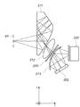
図2は、第1実施形態における頭部装着型の映像表示装置であるところの、HMD301の映像表示部を光軸に平行な面で切断した断面図である。図2において、液晶表示素子202は、入射された直線偏光光線の偏光方向を変えて反射させることで2次元の映像を表示する反射型の液晶表示素子である。光源ユニット220は、上記反射型の液晶表示素子202を照明する光源として機能する。光源ユニット220から射出された光線は、ハーフミラー213で反射され、液晶表示素子202に入射する。反射型の液晶表示素子202では、表示された映像情報に応じて入射光の偏光方向を変化させ、入射光を反射させる。液晶表示素子202で反射された光線は、再びハーフミラー213を透過し、偏光板205を透過することで、観察可能な映像となる。偏光板205を透過した光線は、レンズ212、接眼プリズム211によって拡大され、観察者の眼球EPに射出される。ハーフミラー213、偏光板205、レンズ212、接眼プリズム211は接眼光学系を形成する。
FIG. 2 is a cross-sectional view of the image display unit of the
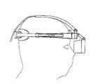
図3は、本実施形態によるHMD301の外観を示す斜視図である。また、図4は、HMD301を中心で切断した断面図を示す。これらの図を用い、後頭部パッドで観察者の頭部を押圧する構成について詳述する。
FIG. 3 is a perspective view showing an appearance of the
観察者がHMD301を装着する際には、頭頂部押圧部材としての頭頂パッド302、後頭部押圧部材としての後頭部パッド303、側頭部押圧部材としての側面部パッド304、前頭部押圧部材としてのフロントパッド305が観察者の頭部に接触する。
When the observer wears the
HMD本体表示部306は、その内部に図2にて説明した光学ユニットを左右両眼に対し、各々1台ずつ配置されている。即ち、HMD本体表示部306は、映像表示素子としての液晶表示素子202と図2に示した接眼光学系を内包したケース部材にて構成されている。また、HMD本体表示部306には、HMD301を装着した観察者の前頭部を押圧するようにフロントパッド305が設けられている。
In the HMD main
HMD本体表示部306の左右両側にはサイドフレーム307が配置され、これらは後頭部ユニット308に接続される。即ち、サイドフレーム307は、HMD本体表示部306を形成する上記ケース部材より、装着時の観察者の側頭部方向へ延びる側頭部支持部材として機能する。サイドフレーム307には、装着時の観察者の側頭部を押圧するための側面部パッド304が設けられている。
また、後頭部ユニット308の内部には、HMD本体表示部306とコントローラユニット(不図示)間の信号を中継するための中継基板が配置されている。なお、この中継基板は、後頭部ユニット308内に配置することに限定されるわけではない。HMD本体表示部306側に中継基板を配置して全ての機能を集約させても良いが、このような構成ではHMD本体表示部306が非常に重くなってしまう。HMD本体表示部306が重くなってしまうと、HMDを装着する観察者は前側につんのめっているように感じてしまい、快適な装着感を得ることができない。そこで、本実施形態では、HMD301全体の重量バランスを考慮して、前後に重量を分散させることにより、HMD301の重心位置を、観察者の頭の中心位置に近づける構成としている。即ち、中継基板を後頭部ユニット308内に配置し、重量配分の最適化を図っている。
In addition, a relay board for relaying signals between the HMD main
本実施形態では、HMD本体表示部306と後頭部ユニット308間は、上述のサイドフレーム307以外に、頭頂フレーム309でも接続されている。頭頂フレーム309には、頭頂パッド302が取り付けられており、観察者の頭頂部を支持する。頭頂パッド302を支持する軸にはネジ溝が切られており、つまみ310を回すことで頭頂パッド302を上下に動かすことが可能である。この構成により、頭頂パッド302を各個人の頭のサイズに合わせて上下させて、観察者にとって見やすい位置に調節することができる。即ち、本実施形態のHMD301は、HMD本体表示部306を形成する上記ケース部材より、装着時の観察者の頭頂部方向へ延びる頭頂部支持部材としての頭頂フレーム309を有する。そして、この頭頂フレーム309には、装着時の観察者の頭頂部を押圧するように頭頂パッド302が設けられている。
In this embodiment, the HMD main
頭頂フレーム309には、更に、後頭部アーム311が回動可能に接続されており、その回動中心である回動部309aは、頭頂フレーム309の後方に設けられている。後頭部アーム311の、頭頂フレーム309との接続部と反対側の端部には、後頭部パッド303が接続されている。後頭部パッド303は、装着時に観察者の後頭部を押圧する。また、サイドフレーム307には、装着時に、観察者の頭部サイズに合わせて観察者の頭部を締め付けるための、長さを調整可能なヘッドバンド312が配置されている。後頭部アーム311は、ヘッドバンド312とも連結されている。即ち、後頭部アーム部材は、頭頂部支持部材としての頭頂フレーム309と回動可能に連結する回動部と、バンド部材としてのヘッドバンド312と連結する連結部を有する後頭部支持部材である。なお、この後頭部支持部材は、装着時の観察者の後頭部側より下方向へ延びるように設けられており、該観察者の後頭部を押圧するための後頭部パッド303を有する。そして、ヘッドバンド312の長さの調整に応じて後頭部アーム311は回動部309aを中心として回動し、この回動により後頭部パッド303が観察者の後頭部を押圧する。
Further, a
以下、図4を参照して、後頭部パッド303で観察者の頭部を押圧する構成について更に詳述する。
Hereinafter, with reference to FIG. 4, the structure which presses an observer's head with the
本実施形態のHMD301において、後頭部アーム311の回転中心、即ち回動部309aの位置は、観察者の後頭部の端点より後ろ側に設置されていることが望ましい。
In the
上述したように、HMD301のサイドフレーム307の内部には、観察者の頭部を締め付けて、装着するためのヘッドバンド312が配置されている。ヘッドバンド312には、観察者がバンドを動かすためのつまみ部314が設けられており、観察者はこのつまみ部314を引っ張ることでヘッドバンド312を前後方向に駆動させることができる。この構成により、ヘッドバンド312は、観察者の頭部サイズに応じてその長さを調整することが可能となっている。
As described above, inside the
また、上述したように、ヘッドバンド312は後頭部アーム311と接続されている。後頭部アーム311の、ヘッドバンド312と接続される連結部には、長穴311aが形成されている。そして、ヘッドバンド312の後ろ側に設けられた軸部313がこの長穴311aと係合するように構成されている。この構成により、ヘッドバンド312を動かすことで、ヘッドバンド312に係合された後頭部アーム311が回動部309aを中心として回動されることになる。そして、この回動により、後頭部アーム311に取り付けられた後頭部パッド303が観察者の後頭部に押圧される。
Further, as described above, the
なお、後頭部パッド303を観察者の頭部にしっかりと押さえつけるように締め付け、緩んでしまうことを防ぐ機構としては、ラック部にギアを噛ませて引っ張り上げ、逆転防止のためのラッチ部を形成した構成などが考えられる。もちろん構成はこの方法に限定されるわけではなく、緩み防止のための機構がついていれば周知のいかなる構成も採用可能であることは言うまでもない。
As a mechanism to prevent the loose
また、このとき、ヘッドバンド312に設けられた軸部313と係合する、後頭部アーム311に設けられた長穴311aは、長穴形状を有している。このため、ヘッドバンド312に対する後頭部アーム311の動きをガイドする機能を持たせることができる。即ち、長穴311aと軸部313との係合により、両者は一方向への相対的な位置変化が可能となっている。その結果、後頭部アーム311がねじれて後頭部パッド303による均一な押圧力が得られなくなること、あるいは、後頭部アーム311の動きがこじってしまい、動かなくなるといった問題の発生を防ぐことが可能となる。より詳細には、長穴311aと軸部313が係合することで後頭部アーム311がねじれることなく回動部309a周りの回転運動だけを行えるようになる。ヘッドバンドを移動させるためのつまみ314は左右両側にあり、均等に引っ張れば問題ないが、片側だけを引っ張る動作が行われると、後頭部アーム311はねじれの力を受ける。そのため、後頭部パッドの左右の位置がずれ、観察者に対して左右均等にあたらなくなる恐れがある。また、後頭部アーム311がねじれることで、回動部309aの軸をこじってしまい後頭部パッド303が駆動しなくなる恐れがある。これらの問題に対して、長穴311aと軸部313が係合することで後頭部アーム311のねじれを規制し、良好な駆動を提供できる。なお、連結部において長穴311aを用いたが、細長の溝形状を用いることも可能であることはいうまでもない。
At this time, the
また、後頭部パッド303にかかる力の反力は、ヘッドバンド312と後頭部アーム311とが係合されている軸部313の部分で受けており、後頭部アーム311の回転中心軸には過大な力がかからないようになっている。このため、回動部309aを強固に作る必要がなくなり、装置全体の軽量化を実現できる。このように、本実施形態によれば、材料自体の強度をそれほど強くすることなく、観察者の後頭部を押圧する部分でのねじれ、たわみを防ぎ、快適な装着感を提供することができる。
The reaction force of the force applied to the
続いて、後頭部パッド303で観察者の頭部を押圧する状態について詳述する。本実施形態のHMD301では、頭頂フレーム309上に設けられた後頭部アーム311の回転中心位置である回動部309aは、観察者の後頭部の端点より後ろ側としている。このような位置に後頭部アーム311の回転中心を配置すると、後頭部アーム311が回転したときの後頭部パッド303の軌跡は、下凸の円弧上になる。そして、このような軌跡で後頭部パッド303が観察者の後頭部を押圧すると、後頭部パッド303は、観察者の後頭部に対して下側から(即ち、後頭部の下部分から)押し上げるように接触することになる。
Subsequently, a state where the observer's head is pressed with the
以上のような構成により、後頭部パッド303により発生する押圧力は、観察者の頭部を押し上げるような力として作用することになる。この力の反作用は、HMD301を押し下げ、観察者の頭部に押し付けるように作用する。従って、このHMD301を下方向に押し付ける力によって、装着時におけるHMD301のぐらつきを防ぐことができ、観察者の頭部にHMD301をしっかり固定できるため、観察者は快適な装着感を得ることができる。
With the above configuration, the pressing force generated by the
図5は、HMD301を観察者の頭頂から垂直下向き方向に見た図である。図5に示すように、後頭部パッド303は、上記垂直下向の軸周り(頭頂パッド302による装着時の押圧方向の軸周り)に円弧形状を描くような形状になっている。このような形状にすることで、観察者の後頭部を押圧する際に、円弧形状の両端部が観察者に先に当たり、この部分が撓んでバネ力が発生する。このバネ力は、後頭部パッドの両端部を、観察者の頭部中心方向に押圧するように機能する。後頭部パッド303の円弧部分の両端2ヶ所で観察者の頭部を中心方向に押圧するため、後頭部パッド303はぐらつくことなく安定する。
FIG. 5 is a view of the
また、後頭部パッド303が押圧される部分には、『盆の窪』と呼ばれるツボがある。後頭部パッド303は、この盆の窪と呼ばれるツボの周辺部を押圧するため、観察者は後頭部パッド303が押圧されることによる不快感をあまり感じずにすむという利点も有している。より具体的には、後頭部パッド303を頭頂部から見てR75以下くらいの曲率半径で形成すると、後頭部パッド303の両端部が観察者に先に当たり、盆の窪の周辺部を押圧でき、より快適な装着感を提供できる。
In addition, there is an acupuncture point called “Bon's depression” in the portion where the
以上、詳述したとおり、本実施形態のHMD301では、観察者の後頭部を押圧する後頭部パッド303が後頭部アーム311に接続され、後頭部アーム311の回転中心が観察者の後頭部の端点より後ろ側の頭頂フレーム上に設置される。このような構成により、観察者がHMD301を装着すると、観察者の後頭部を押し上げるように後頭部パッド303が当接するので、快適な装着感を得ることが可能となる。
As described above, in the
さらには、後頭部パッド303は、観察者の頭頂から下に向かう垂直な軸に対して円弧を描くような形状になっている。このような形状にすることで、観察者の後頭部を押圧する際に、観察者の『盆の窪』の周辺部を、観察者の頭部の中心方向に押圧するように機能する。そのため、後頭部パッド303はぐらつくことなく安定して観察者に押圧されるとともに、観察者に快適な装着感を提供することが可能となる。
Further, the
Claims (4)
映像表示素子と接眼光学系を内包し、当該映像表示装置を装着した観察者の前頭部を押圧するように設けられた前頭部押圧部材を有するケース部材と、
前記ケース部材より、装着時の観察者の頭頂部方向へ延びる頭頂部支持部材であって、該観察者の頭頂部を押圧するように設けられた頭頂部押圧部材を有する頭頂部支持部材と、
前記ケース部材より、装着時の観察者の側頭部方向へ延び、長さを調整可能なバンド部材を有する側頭部支持部材と、
前記頭頂部支持部材と回動可能に連結する回動部及び前記バンド部材と連結する連結部を有し、装着時の観察者の後頭部側を下方向へ延びるアーム部材と、該観察者の後頭部を押圧するように前記アーム部材の前記連結部を挟んで前記回動部とは反対側の端部に設けられた後頭部押圧部材とを有する後頭部支持部材とを備え、
前記バンド部材の長さの調整に応じて前記連結部が前記アーム部材を前記回動部を中心として回動させることを特徴とする頭部装着型の映像表示装置。 A head-mounted image display device,
A case member having a forehead pressing member that includes an image display element and an eyepiece optical system and is provided so as to press the forehead of an observer wearing the image display device;
A head support member extending from the case member toward the top of the observer at the time of wearing, the top support member having a top pressing member provided to press the top of the observer; and
From the case member, the temporal support member having a band member that extends in the direction of the temporal region of the observer at the time of wearing and can adjust the length;
An arm member has a connecting portion connecting the pivot portion and the band member, extending the back head side of the attachment when the observer downward to linked to the top of the head support member and rotation, occipital of the observer the the rotating unit across the connecting portion of the arm member to press a back of the head supporting member having a back head pressing member provided at the opposite end, and
A head-mounted image display device, wherein the connecting portion rotates the arm member around the rotating portion in accordance with the adjustment of the length of the band member .
前記連結部は、前記軸部と係合し、前記軸部が前記アーム部の長手方向に沿って移動可能な溝形状、あるいは穴形状を有することを特徴とする請求項1に記載の頭部装着型の映像表示装置。 The band member has a shaft portion for engaging with the arm member,
2. The head according to claim 1, wherein the connecting portion engages with the shaft portion, and the shaft portion has a groove shape or a hole shape that is movable along a longitudinal direction of the arm portion. Wearable video display device.
Priority Applications (3)
| Application Number | Priority Date | Filing Date | Title |
|---|---|---|---|
| JP2007089044A JP4958599B2 (en) | 2007-03-29 | 2007-03-29 | Head-mounted video display device |
| US12/055,783 US8237626B2 (en) | 2007-03-29 | 2008-03-26 | Head-mounted display |
| US13/542,364 US20120268352A1 (en) | 2007-03-29 | 2012-07-05 | Head-mounted display |
Applications Claiming Priority (1)
| Application Number | Priority Date | Filing Date | Title |
|---|---|---|---|
| JP2007089044A JP4958599B2 (en) | 2007-03-29 | 2007-03-29 | Head-mounted video display device |
Publications (3)
| Publication Number | Publication Date |
|---|---|
| JP2008252319A JP2008252319A (en) | 2008-10-16 |
| JP2008252319A5 JP2008252319A5 (en) | 2010-05-20 |
| JP4958599B2 true JP4958599B2 (en) | 2012-06-20 |
Family
ID=39793400
Family Applications (1)
| Application Number | Title | Priority Date | Filing Date |
|---|---|---|---|
| JP2007089044A Expired - Fee Related JP4958599B2 (en) | 2007-03-29 | 2007-03-29 | Head-mounted video display device |
Country Status (2)
| Country | Link |
|---|---|
| US (2) | US8237626B2 (en) |
| JP (1) | JP4958599B2 (en) |
Families Citing this family (18)
| Publication number | Priority date | Publication date | Assignee | Title |
|---|---|---|---|---|
| JP4958599B2 (en) * | 2007-03-29 | 2012-06-20 | キヤノン株式会社 | Head-mounted video display device |
| JP5268801B2 (en) * | 2009-06-26 | 2013-08-21 | キヤノン株式会社 | Head-mounted display device |
| GB2474083B (en) * | 2009-10-05 | 2015-12-23 | Keeler Ltd | Improvements in and relating to ophthalmic instruments |
| JP2012058530A (en) | 2010-09-09 | 2012-03-22 | Seiko Epson Corp | Shutter spectacles and image display system |
| EP3117263B1 (en) * | 2014-03-14 | 2018-05-09 | Sony Interactive Entertainment Inc. | Methods and systems tracking head mounted display (hmd) and calibrations for hmd headband adjustments |
| US10108016B2 (en) | 2014-08-20 | 2018-10-23 | Microsoft Technology Licensing, Llc | Headband comfort and fit adjustment mechanisms |
| JP6146422B2 (en) * | 2015-01-06 | 2017-06-14 | ブラザー工業株式会社 | Image display device and head mounted display |
| EP4250883A3 (en) | 2015-02-27 | 2023-11-29 | Sony Interactive Entertainment Inc. | Head-mounted display |
| EP3196687B1 (en) * | 2016-01-20 | 2020-03-11 | Canon Kabushiki Kaisha | Head mounted device |
| JP6686504B2 (en) * | 2016-02-15 | 2020-04-22 | セイコーエプソン株式会社 | Head-mounted image display device |
| JP6686503B2 (en) * | 2016-02-15 | 2020-04-22 | セイコーエプソン株式会社 | Head-mounted image display device |
| CN205826967U (en) * | 2016-06-22 | 2016-12-21 | 北京蚁视科技有限公司 | A kind of interpupillary distance self adaptation head-mounted display apparatus |
| US10901224B2 (en) * | 2017-04-28 | 2021-01-26 | Intel Corporation | Neck mounted computing device with display connectivity |
| US10539792B1 (en) * | 2017-05-19 | 2020-01-21 | Facebook Technologies, Llc | Apparatus, system, and method for adjusting head-mounted-display straps |
| CN109752849B (en) * | 2017-11-03 | 2021-05-18 | 宏达国际电子股份有限公司 | Head-mounted display device |
| US10905186B2 (en) * | 2018-05-03 | 2021-02-02 | Htc Corporation | Head-mounted display device |
| CN110824704B (en) * | 2018-08-13 | 2023-03-14 | 宏达国际电子股份有限公司 | Head-mounted display device |
| CN111983810A (en) * | 2020-08-20 | 2020-11-24 | 义乌工商职业技术学院 | A glasses device for AR teaching |
Family Cites Families (16)
| Publication number | Priority date | Publication date | Assignee | Title |
|---|---|---|---|---|
| JPH09179061A (en) * | 1995-10-23 | 1997-07-11 | Olympus Optical Co Ltd | Head mounted type video display device |
| JPH09304724A (en) * | 1996-05-15 | 1997-11-28 | Sony Corp | Optical visual device |
| JPH10142551A (en) * | 1996-11-06 | 1998-05-29 | Olympus Optical Co Ltd | Head mounted picture display device |
| JP3884850B2 (en) * | 1997-12-11 | 2007-02-21 | キヤノン株式会社 | Video display device |
| US6388640B1 (en) * | 1998-01-09 | 2002-05-14 | Canon Kabushiki Kaisha | Head mount display |
| JP3102427B1 (en) * | 1999-05-18 | 2000-10-23 | 住友電気工業株式会社 | Polycrystalline diamond tools |
| JP2001069428A (en) * | 1999-08-26 | 2001-03-16 | Olympus Optical Co Ltd | Head mount display device |
| JP3880294B2 (en) * | 2000-07-19 | 2007-02-14 | キヤノン株式会社 | Head mounting mechanism and head mounting device using the same |
| JP3576985B2 (en) * | 2001-02-28 | 2004-10-13 | キヤノン株式会社 | Position adjustment mechanism and head mounted display device |
| WO2004061519A1 (en) * | 2002-12-24 | 2004-07-22 | Nikon Corporation | Head mount display |
| JP2005027867A (en) | 2003-07-14 | 2005-02-03 | Hideo Nishina | Griddle apparatus |
| JP4447999B2 (en) * | 2004-10-01 | 2010-04-07 | キヤノン株式会社 | Head mounting device and head mounting system |
| JP4402018B2 (en) * | 2005-07-04 | 2010-01-20 | キヤノン株式会社 | Head-mounted device |
| JP2007049684A (en) * | 2005-07-13 | 2007-02-22 | Canon Inc | Mounting mechanism and head mounting type image display device |
| JP4958599B2 (en) * | 2007-03-29 | 2012-06-20 | キヤノン株式会社 | Head-mounted video display device |
| JP5004752B2 (en) * | 2007-10-26 | 2012-08-22 | キヤノン株式会社 | Head-mounted device |
-
2007
- 2007-03-29 JP JP2007089044A patent/JP4958599B2/en not_active Expired - Fee Related
-
2008
- 2008-03-26 US US12/055,783 patent/US8237626B2/en not_active Expired - Fee Related
-
2012
- 2012-07-05 US US13/542,364 patent/US20120268352A1/en not_active Abandoned
Also Published As
| Publication number | Publication date |
|---|---|
| US20120268352A1 (en) | 2012-10-25 |
| US20080238815A1 (en) | 2008-10-02 |
| JP2008252319A (en) | 2008-10-16 |
| US8237626B2 (en) | 2012-08-07 |
Similar Documents
| Publication | Publication Date | Title |
|---|---|---|
| JP4958599B2 (en) | Head-mounted video display device | |
| US5371556A (en) | Spectacle type retina direct display apparatus | |
| JP5594258B2 (en) | Head mounted display | |
| WO2004017120A1 (en) | Image display device | |
| JP5589992B2 (en) | Head mounted display | |
| US11194165B2 (en) | Wearable display device | |
| JP2007243649A (en) | Head-mounted type video display device | |
| JPH08166557A (en) | Head mounted display device | |
| JP2009092808A (en) | Helmet-mounted display device | |
| US11467413B2 (en) | Wearable display device | |
| JPH10293544A (en) | Head-mount type video display device | |
| JP4258950B2 (en) | Video display device | |
| WO2013027714A1 (en) | Head-mounted display | |
| JP5614386B2 (en) | Head mounted display | |
| JP6428808B2 (en) | Head mounted display | |
| JP5363390B2 (en) | Head-mounted image display device | |
| JPH08251510A (en) | Head mount type video display device | |
| JP6164231B2 (en) | Head mounted display and image display device | |
| JP5648603B2 (en) | Head mounted display | |
| JP5838880B2 (en) | Head mounted display | |
| JPH11133349A (en) | Mead-mounted type display device | |
| JP2001209000A (en) | Video display device | |
| JP3383733B2 (en) | Head-mounted display | |
| JP2008134471A (en) | Display device | |
| JP2003307701A (en) | Mechanism for adjusting width between eyes and personal viewer device using the same |
Legal Events
| Date | Code | Title | Description |
|---|---|---|---|
| A521 | Written amendment |
Free format text: JAPANESE INTERMEDIATE CODE: A523 Effective date: 20100329 |
|
| A621 | Written request for application examination |
Free format text: JAPANESE INTERMEDIATE CODE: A621 Effective date: 20100329 |
|
| A977 | Report on retrieval |
Free format text: JAPANESE INTERMEDIATE CODE: A971007 Effective date: 20120309 |
|
| TRDD | Decision of grant or rejection written | ||
| A01 | Written decision to grant a patent or to grant a registration (utility model) |
Free format text: JAPANESE INTERMEDIATE CODE: A01 Effective date: 20120316 |
|
| A01 | Written decision to grant a patent or to grant a registration (utility model) |
Free format text: JAPANESE INTERMEDIATE CODE: A01 |
|
| A61 | First payment of annual fees (during grant procedure) |
Free format text: JAPANESE INTERMEDIATE CODE: A61 Effective date: 20120319 |
|
| FPAY | Renewal fee payment (event date is renewal date of database) |
Free format text: PAYMENT UNTIL: 20150330 Year of fee payment: 3 |
|
| LAPS | Cancellation because of no payment of annual fees |