JP4956424B2 - Apparatus and method for performing coordinate measurements - Google Patents
Apparatus and method for performing coordinate measurements Download PDFInfo
- Publication number
- JP4956424B2 JP4956424B2 JP2007513713A JP2007513713A JP4956424B2 JP 4956424 B2 JP4956424 B2 JP 4956424B2 JP 2007513713 A JP2007513713 A JP 2007513713A JP 2007513713 A JP2007513713 A JP 2007513713A JP 4956424 B2 JP4956424 B2 JP 4956424B2
- Authority
- JP
- Japan
- Prior art keywords
- clock signal
- time
- unit
- measuring
- sampling clock
- Prior art date
- Legal status (The legal status is an assumption and is not a legal conclusion. Google has not performed a legal analysis and makes no representation as to the accuracy of the status listed.)
- Expired - Fee Related
Links
Images


Classifications
-
- G—PHYSICS
- G01—MEASURING; TESTING
- G01B—MEASURING LENGTH, THICKNESS OR SIMILAR LINEAR DIMENSIONS; MEASURING ANGLES; MEASURING AREAS; MEASURING IRREGULARITIES OF SURFACES OR CONTOURS
- G01B21/00—Measuring arrangements or details thereof, where the measuring technique is not covered by the other groups of this subclass, unspecified or not relevant
- G01B21/02—Measuring arrangements or details thereof, where the measuring technique is not covered by the other groups of this subclass, unspecified or not relevant for measuring length, width, or thickness
- G01B21/04—Measuring arrangements or details thereof, where the measuring technique is not covered by the other groups of this subclass, unspecified or not relevant for measuring length, width, or thickness by measuring coordinates of points
- G01B21/045—Correction of measurements
Abstract
Description
本発明は、ワークピースの座標測定を行うための装置および方法に関する。 The present invention relates to an apparatus and method for measuring the coordinates of a workpiece.
数値制御された工作機械、特にフライス盤において、自動座標測定を行うために、切換プローブヘッドを使用することが多い。このようなプローブヘッドは、測定子が例えばワークピースの表面のような障害物に接触した際に、切換事象を引起す測定子を自由にできる。代表的な自動測定に関する適用分野は、ワークピースの整向、基準点の設定、品質管理のためのワークピースの測定並びに三次元ワークピースの表面のデジタル化である。 In a numerically controlled machine tool, especially a milling machine, a switching probe head is often used to perform automatic coordinate measurement. Such a probe head frees the probe that causes a switching event when the probe contacts an obstacle, such as the surface of a workpiece. Typical areas of application for automated measurements are workpiece orientation, reference point setting, workpiece measurement for quality control, and 3D workpiece surface digitization.
測定を行うために、プローブヘッドは工具に代わって工具スピンドル内に挿入される。これによりプローブヘッドは工作機械を数値制御することにより様々な座標軸内に位置決めすることができる。座標測定を行うために、プローブヘッドは数値制御により制御された状態で、ワークピースの表面に達するまでワークピースに向って移動する。この過程は接触過程と呼ばれる。接触過程時に、プローブヘッドの空間位置は測定されるべき座標軸において、数値制御のサイクルタイムから決定される時間間隔に連続的に、位置測定装置を用いて測定され、位置の値を数値制御部転送する。位置の値は数値制御により、内部制御回路のための位置実測値として必要である。通常のサイクルタイムは例えば長さが50μsである。 In order to make measurements, the probe head is inserted into the tool spindle instead of the tool. Thereby, the probe head can be positioned in various coordinate axes by numerically controlling the machine tool. To perform coordinate measurements, the probe head moves toward the workpiece until it reaches the surface of the workpiece, as controlled by numerical control. This process is called a contact process. During the contact process, the spatial position of the probe head is measured on the coordinate axis to be measured using a position measuring device continuously at a time interval determined from the cycle time of numerical control, and the position value is transferred to the numerical controller. To do. The position value is necessary as an actual position value for the internal control circuit by numerical control. The normal cycle time is, for example, 50 μs in length.
この手順の場合位置の値は固定した時間間隔で時間的に不連続に確定されるので、これに対して切換事象は非同期に現れ、接触速度が高いほどあるいはサイクルタイムが長いほど一層大きくなる測定誤差が生じる。この測定誤差は工作機械の共通の測定誤差に積算される。例えば先に挙げたサイクルタイムが50μsで接触速度が1m/minであると、約0.83μmの最大位置誤差が生じる。これはプローブヘッドが1m/minの接触速度の場合に50μsで戻る距離に相当する。この大きさの別の位置誤差は多くの場合受入れられない。 In the case of this procedure, the position value is determined discontinuously in time at fixed time intervals, on the other hand, the switching event appears asynchronously, a measurement that increases as the contact speed increases or the cycle time increases. An error occurs. This measurement error is added to the common measurement error of machine tools. For example, when the cycle time mentioned above is 50 μs and the contact speed is 1 m / min, a maximum position error of about 0.83 μm occurs. This corresponds to the distance that the probe head returns in 50 μs when the contact speed is 1 m / min. Another position error of this magnitude is often unacceptable.
サイクルタイムは従来技術により知られているような数値制御により影響を受けないので、時間的に不連続な作動モードにより生じる別の位置誤差を軽減するための唯一の可能性は大抵の場合、接触速度を落とすことである。しかしながらこれによりスループットはわずかになり、従ってコストは上がる。 Since cycle time is not affected by numerical control as known from the prior art, the only possibility to reduce another position error caused by temporally discontinuous operating modes is in most cases contact To slow down. However, this reduces throughput and therefore increases costs.
特許文献1には高い接触速度と小さい位置誤差の間の妥協が記載されている。これには第一接触が高い接触速度で行われ、プローブヘッドが短い区間で引き続いて、ワークピース表面から遠ざかり、接触が低い接触速度でもって繰り返される、座標測定を行うための方法が提案されている。第二接触の際に接触速度が低いことにより、高い精度が得られる。この方法の短所は、数値制御のプログラムに高い要求が出され、消費時間が二度の方向転換によりほんのわずかばかり増えることである。
本発明の課題は、高い精度と関連して接触速度が高い、座標測定を行うための方法を提供することである。 The object of the present invention is to provide a method for performing coordinate measurements with a high contact speed associated with high accuracy.
この課題は、請求項1による方法により解決される。この方法の有利な詳細内容は請求項1に依存した従属請求項からわかる。
This problem is solved by the method according to
さらに本発明の課題は、ワークピースの座標の測定が高い接触速度でもって同時に精度が高い場合に行うことができる、座標測定を行うための装置を提供することである。 It is a further object of the present invention to provide an apparatus for performing coordinate measurements that can be performed when workpiece coordinates are measured with high contact speed and at the same time high accuracy.
この課題は請求項6による座標測定を行うための装置により解決される。座標測定を行うためのこの装置の有利な詳細内容は請求項6に従属した請求項から明らかになる。 This problem is solved by a device for measuring coordinates according to claim 6. Advantageous details of this device for making coordinate measurements will become apparent from the claims dependent on claim 6.
ワークピースが接触する際切換信号を発生させる走査プローブと、プローブヘッドの相対位置が測定可能である、各測定されるべき座標軸用の位置測定ユニットと、制御クロック信号の時間間隔で時間的に不連続に作動する処理ユニットとを備えた座標測定を行うための装置を提案する。座標測定を行うために、位置測定の値はサンプリングクロック発生器により発生し、かつ処理ユニットの制御クロック信号よりも高い周波数を備えたサンプリングクロック信号の時間間隔で測定される。位置測定値は位置データメモリ部内に記憶される。時間測定ユニットにおいて、時間間隔Δtは制御クロック信号のパルスと切換するプローブヘッドでの切換信号の発生の間で確定される。最後に測定された時間間隔Δtに基づき、処理ユニットあるいは位置測定ユニットにおいて切換信号の発生の時点に最も近いデータメモリ部内の位置の値が確定される。 A scanning probe that generates a switching signal when the workpiece contacts, a position measuring unit for each coordinate axis to be measured that can measure the relative position of the probe head, and a time interval between control clock signals. A device for performing coordinate measurements with a processing unit that operates continuously is proposed. In order to make coordinate measurements, the value of the position measurement is generated by a sampling clock generator and measured at the time interval of the sampling clock signal with a higher frequency than the control clock signal of the processing unit. The position measurement value is stored in the position data memory unit. In the time measuring unit, the time interval Δt is determined between the generation of a switching signal at the probe head that switches with the pulse of the control clock signal. Based on the last measured time interval Delta] t, the value of the position of the nearest data memory unit at the time of occurrence of the switching signal in the processing unit or the position measurement unit is determined.
サンプリングクロック発生器と位置の値の記憶に関する位置メモリ部が位置測定ユニット内に設けられていると特に有利である。なぜなら位置測定ユニットから処理ユニットへ転送しなければならない位置の値の数が著しく減少するからである。このことは位置測定ユニットと処理ユニット間のデータ転送がシリアルインタフェースを介して行われると特に有効である。 It is particularly advantageous if a position memory unit for storing the sampling clock generator and the position value is provided in the position measuring unit. This is because the number of position values that must be transferred from the position measurement unit to the processing unit is significantly reduced. This is particularly effective when data transfer between the position measuring unit and the processing unit is performed via a serial interface.
さらにその時点が処理ユニットの制御クロック信号に対して測定される切換事象の発生と位置測定値の間の正確な時間的関連付けを提供するために、サンプリングクロック信号を制御クロック信号と同期させると特に有利である。 In addition, the sampling clock signal is particularly synchronized with the control clock signal in order to provide an accurate temporal association between the occurrence of the switching event and the position measurement whose time is measured relative to the control clock signal of the processing unit. It is advantageous.
本発明の別の長所並びに詳細は、図に基づいた座標測定を行うための装置及び座標測定を行うための方法の以下の記載内容から明らかになる。 Further advantages and details of the present invention will become apparent from the following description of the apparatus and the method for performing coordinate measurements based on the figures.
図1は本発明による座標測定装置の好ましい実施例のブロック図を示す。装置は測定子12を備えたプローブヘッド10、測定されるべき各座標軸線のための位置測定ユニット20、ならびに処理ユニット30から構成されている。
FIG. 1 shows a block diagram of a preferred embodiment of a coordinate measuring device according to the invention. The apparatus comprises a
測定子12がワークピースと接触する際に振り出すと、プローブヘッド10は切換信号を発生させる。切換信号は切換導線11を経由して処理ユニット30に達し、接触過程が終了されていることを信号で伝える。切換導線11は、従来のケーブル接続であっても、赤外線転送区間であってもよい。
If the
処理ユニット30は原則的に数値制御システムである。数値制御システムは、プローブヘッド10の位置決めを行う駆動部を制御するのに適した別の制御回路を含んでいる。このような数値制御システムは公知であり、かつ本願発明の対象ではない。従って以下に本発明と関連している機能だけを説明するにとどめる。
The
処理ユニット30内には、制御クロック発生器31と、制御ユニット33と、時間測定ユニット34が設けられている。
In the
制御クロック発生器31により、制御ユニット33は制御クロック信号32を用いて時間基盤(Zeitbasis)を任意に処理することができる。この時間基盤は、どの周波数で制御ユニット33内の制御回路を作動させるか、あるいはどの時間間隔により、位置測定値が位置測定ユニット20に要求されるかを確定する。制御クロック信号32の周期はサイクルタイムとも呼ばれる。
The
制御ユニット33は接触動作を制御する。位置測定値の要求及び転送に関して、制御ユニットは第一データ転送チャンネル35を経由して位置測定ユニット20と接続している。この好ましい実施形態において、データ転送はシリアル方式で行われる。
The
時間測定ユニット34は制御クロック周期の開始とプローブヘッド10の切換事象との間の時間Δtを測定するために使用される。制御クロック周期の開始としてこの場合通常、制御クロック信号32の立上り側面あるいは立下り側面のどちらかが選択される。時間測定ユニット34は第二データ転送チャンネル36を経由して制御ユニット33と接続している。さらに時間測定ユニットにはプローブヘッド10の切換信号が切換導線11を経由して供給される。第二データ転送チャンネル36を経由して、時間測定ユニット34は制御ユニット33により各制御クロック周期の開始までリセットされ、かつ新たに開始される。さらに第二データ転送チャンネル36を経由して、切換事象があったことが制御ユニット33に信号で伝えられ、かつその時間Δtが伝達される。
The
位置測定ユニット20は、位置測定装置21と、サンプリングクロック発生器22と、位置データメモリ部24と、インタフェースユニット25とで構成されている。図1には位置測定ユニット20を一つだけ示してあるが、当業者にとって、測定されるべき座標軸の数に応じて、複数の位置測定ユニット20が必要であることは明らかである。
The
サンプリングクロック発生器22と同様、位置データメモリ部24も位置測定ユニット20内に設けられていることは特に有利である。なぜならこのことにより処理ユニット30まで転送しなければならない位置の値の数が削減されるからである。この長所は特に、位置測定ユニット20と処理ユニット30の間のデータ交換がシリアルインタフェースを介して行われる場合に効力を発する。データ転送レートが例えば2Mバイトであると、位置の値のシリアル転送は32ビット幅で少なくとも16μsかかる。処理ユニット30のサイクルタイムとして先にすでにふれた50μsが前提とされた場合、制御クロック信号32の周期に応じて、最大でも二つの別の位置の値が測定される。この制限は図1で提案した位置測定ユニット20の構成により回避される。
As with the
位置測定装置21以外に、デジタル方式の位置データを自由に扱える公知の位置測定装置を使用してもよい。サンプリングクロック発生器22により、時間ラスター(Raster)を予め設定するサンプリングクロック信号23が発生し、このサンプリングクロック信号において位置の値は、接触過程時に位置測定装置21から要求される。この際サンプリングクロック信号23は制御クロック信号32よりも高い周波数を有する。この場合サンプリングクロック信号23の周波数にとって、制御クロック信号32の周波数の整数倍の量が選択され場合に特に有利である。さらに両クロック信号間の正確な時間関係を提供するために、サンプリングクロック信号23を制御クロック信号32と同期させることは有利である。
In addition to the
インタフェースユニット25は第一データ転送チャンネル35を経由して制御ユニット33と接続している。インタフェースユニット25を経由して、位置の値は位置データメモリ部24からか、あるいは位置測定装置21から直接要求され、かつ制御ユニット33へ転送される。さらにインタフェースユニットにより、サンプリングクロック発生器22は同期信号26を自由に使用でき、インタフェースユニットに第一データ転送チャンネル35を経由して対応するコマンドが伝達されると、検出と位置の値のメモリは停止する。
The
位置データは位置データメモリ部24内に記憶される。位置データメモリ部24は、
少なくとも接触経過の終了後、接触時間点に時間的に最も近くにある位置の値が、位置データメモリ部24内にあるように、多数のメモリセルを備えている。もはや必要とされない位置の値を含むメモリセルは上書きされる。従って位置データメモリ部24が周期的に上書き可能なリングメモリとして構成されていると、すなわちメモリされるべき位置の値が、最も古く、もはや必要ではない位置データメモリ部24内の位置の値を上書きすると有利である。
The position data is stored in the position
A plurality of memory cells are provided so that the value of the position closest in time to the contact time point is in the position
位置データメモリ部24のためのメモリ必要条件の確定を以下の例で説明する。サンプリングクロック信号23の周波数が制御クロック信号32の周波数の10倍に相当し、処理ユニット30と位置測定ユニット20の間の伝達が、制御クロック信号32の周期の間隔で時間的に不連続に行われた場合、制御クロック周期毎に10個の位置の値をメモリしなければならない。このことはプローブヘッド10からの切換信号が二つの伝達時点間のどの任意の時点に対しても発生してよいことにその根拠がある。したがって処理ユニット30が位置測定ユニット20に最後にアクセスして以降測定された、位置データメモリ部24内の位置の値はどれでも、切換信号の発生の時点に最も近い値になり得る。
The determination of the memory requirements for the position
接触する際プローブヘッド10は処理ユニット30により制御された状態で、測定されるべきワークピースを目指して移動する。この際制御ユニット33により、制御クロック信号32の周期の時間的間隔で連続的に第一データ転送チャンネル35とインタフェースユニット25を経由して、位置測定装置21からの位置の値が要求される。制御ユニット33は駆動部を制御するための制御回路用の位置実測値としてこの位置の値を必要とする。位置データ要求があった場合、インタフェースユニット25は、サンプリングクロック信号23を同期信号26を経由して制御クロック信号32と同期させる。さらに制御ユニット33により、第二データ転送チャンネル36を経由して各々の制御クロック周期の開始まで時間測定ユニット34がリセットされ、かつ新たに開始される。これに平行して、サンプリングクロック信号23の周期の時間的間隔で、位置の値が測定され、かつ位置データメモリ部24内に記憶される。
In contact, the
測定子12がワークピースと接触する際に振り出されると、プローブヘッド10は処理ユニット30に切換導線11上で信号を送る。従って制御ユニット33は駆動部を停止させ、制御クロック周期の開始と切換事象の間の期間Δtは時間測定ユニット34において保持される。さらにまた別の位置データが全く必要とされないことが位置測定ユニット20に伝達されねばならない。このことは例えば図1において、コマンド語の転送によりインタフェースユニット25に至る第一データ転送チャンネル35を経由して行うことができる。これに対する代替え案として、切換導線11を位置測定ユニット20と別に接続し、サンプリングクロック発生器22を切換事象の際に停止させてもよい。
When the
時間間隔Δtと、クロック信号32とサンプリングクロック信号23の間の公知の時間的関係とを用いて、制御ユニット33において、位置データメモリ部24内の、切換事象の発生の時点に最も近い位置のちが確定され、かつ引続く処理のために第一データ転送チャンネル35とインタフェースユニット25を経由して制御ユニット33に転送される。
Time interval Delta] t, by using the known temporal relationship between a
切換事象に最も近い位置の値を確定する際に、切換信号の到着までの所要時間を処理ユニット30に含めるのが特に有利である。このことは切換導線11が電気的導線としてではなく、ワイヤレスの転送区間として形成されている場合には特に有効である。このワイヤレスの転送区間の場合切換信号は例えば赤外線パルスにより転送される。切換信号の転送時間は例えば制御ユニット内に記憶することができる。信号転送時間は本発明の対象ではない。
In determining the value of the position closest to the switching event, it is particularly advantageous to include in the
図2は座標測定を行うための本発明による装置の他の実施形態のブロック図を示す。図1に示した例とは異なり、位置測定ユニット20は各々、図2では評価ユニット27をさらに備えている。その他の構造は図1のものに各々対応している。同じ構成部品は同じ参照符号を備えている。これらの参照符号に関して説明は省略する。
FIG. 2 shows a block diagram of another embodiment of an apparatus according to the invention for performing coordinate measurements. Unlike the example shown in FIG. 1, each of the
プローブヘッド10が切換導線11を経由して処理ユニット30に信号を送ると、すなわちプローブヘッドがワークピースの表面に達すると、この実施形態では、接触時点に最も近い位置の値は、処理ユニット30において制御ユニットにより確定されるのではなく、位置測定ユニット20において評価ユニット27により確定される。この目的で、制御ユニット33は時間測定ユニット34により測定された時間間隔Δtを第一データ転送チャンネル35とインタフェースユニット25を経由して評価ユニット27へ転送する。評価ユニットは時間間隔Δtに基づき、接触時点に最も近い位置データメモリ部24内の位置の値を確定し、かつ位置の値を処理ユニット30へ転送する。
When the
切換信号の転送時間はこの実施形態では、制御ユニット33が測定された時間間隔Δtを包絡線遅延分だけ補正しかつ補正された値を評価ユニット27に転送することによってか、あるいは評価ユニット27が包絡線遅延を結果の確認の際に一緒に含めることにより考慮してもよい。
In this embodiment, the transfer time of the switching signal is determined by the
このことにより接触過程時に性能を利用される制御ユニット33が著しく負荷を軽減されるのはこの方法において特に有利である。
It is particularly advantageous in this way that this greatly reduces the load on the
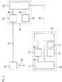
図3は最終的に本発明の第三実施形態のブロック図を示す。前述の例と比較すると、時間測定ユニット34はもはや処理ユニット30内には設けられていない。その代わりに位置測定ユニット20には各々時間測定ユニット34が設けられている。図2の実施形態におけるのと同様に、位置測定ユニット20は図3の例においても評価ユニット27を備えている。他の構造は図1の各々に対応しており、従ってこの構造は再度説明しない。同じ構成部材は同じ参照符号を備えている。
FIG. 3 finally shows a block diagram of the third embodiment of the present invention. Compared to the previous example, the
切換導線11はプローブヘッド10を経由して切換信号を分配し、各時間測定ユニット34と接続し、制御ユニット33と処理ユニット内で接続している。この場合時間測定ユニット34への接続は、切換信号が生じる際時間測定を停止させるために使用される。制御ユニット33は切換導線11を経由して、接触過程が終了し、それと同時に駆動部が停止し、接触で起きた事象に属した位置の値が位置測定ユニット20に要求されることを通知される。この実施形態において切換導線11は空間的に互いに分離して設けられた多数の構成部材と接続しているので、接続が電気的導線を経由してではなく、コードレスの転送区間を経由して行われると特に有利である。適切なコードレスの転送区間は、例えば高周波送信ユニット及び高周波受信ユニット、あるいは赤外線送信機及び赤外線受信機により形成される。
The switching
位置測定ユニット20内において、同期信号26はサンプリングクロック発生器22だけでなく時間測定ユニット34にも供給されている。これにより時間測定ユニット34は各位置データ要求の際にリセット可能である。さらに位置データ要求は制御クロック信号32の時間間隔で時間的に不連続に行われるので、従って時間測定ユニット34内では制御クロック信号32のパルスと切換信号の発生の間の時間間隔Δtも切換するプローブヘッド10において測定可能である。
In the
時間測定ユニット34は評価ユニット27と第二データ転送チャンネル36を経由して接続している。第二データ転送チャンネルを経由して時間測定ユニット34により測定される時間間隔Δtは評価ユニット27へ転送可能である。この情報により、切換信号の発生の時点に切換するプローブヘッド10に最も近い位置の値を確定することが評価ユニット27には可能である。さらにこの実施例において、評価ユニット27が切換事象に最も近い位置の値を確定する際、切換信号の所要時間を考慮するのは有利である。結果として生じる位置の値は、自動的にあるいは処理ユニット30の要求に応じて評価ユニット27からインタフェースユニット25と第一データ転送チャンネル35を経由して制御ユニット33へ転送することができる。
The
この実施形態においては時間間隔Δtの検出も位置測定ユニット20において行われるので、処理ユニット30は前述の例と比較してなおさらに負荷を軽減される。
In this embodiment, since the detection of the time interval Δt is also performed in the
図4は制御クロック信号32と、サンプリングクロック信号23と、プローブヘッド10の切換導線11の間の時間的関係における、座標を測定するための本発明による方法の簡素化された時間ダイヤグラムを示す。この例においてサンプリングクロック信号23は制御クロック信号32の10倍の周波数を有する。
FIG. 4 shows a simplified time diagram of the method according to the invention for measuring coordinates in the time relationship between the
時点t 1 において、制御クロック周期は制御クロック信号32の立上がり側面でもって始まる。この時点において、時間測定ユニット34は第二データ転送チャンネル36を経由してリセットされ、新たに開始される。制御ユニット33により第一データ転送チャンネル35とインタフェースユニット25を経由して、位置測定ユニット20からの位置の値が要求される。位置データ要求と同時に、サンプリングクロック信号23は制御クロック信号32と同期信号26を介して同期される。引き続いて時点t 1 ,t 2 ,...t 10 において、位置測定ユニット20の位置測定装置21において位置の値が各々測定され、位置データメモリ部24内に記憶される。
At time t 1 , the control clock period begins with the rising side of
接触時点t k において、切換導線上でのレベルの変動は測定子12とワークピースの接触を信号で知らせる。従って時間測定ユニット34での時間測定は停止され、制御クロック信号32の立上がり側面に対する切換信号の正確な時点は測定された時間間隔Δtの形式で自由に使用できる。時間間隔Δtは第二データ転送チャンネル36を経由して制御ユニット33へ転送され、この制御ユニット33は引き続き切換事象の発生に最も近い位置の値を確定する。図4の例の場合、時点t 9 において測定された位置の値が接触時点tkに最も近く、従って接触過程の結果である。最後にこの位置の値は第一データ転送チャンネル35を経由して制御ユニット33へ転送され、そこでさらに処理される。
In the contact time t k, the variation in the level of at switching換導line informs the signal contact of the
位置データメモリ部24内の位置の値には正確な測定時点t1,t2,...t10が所属しているので、結果の精度は補間法によりさらに改善することができる。そのために位置の値が予め必要であり、接触時点tkによる位置の値並びに時間間隔Δtの値が予め必要である。接触過程時のプローブヘッド10の送り速度が一定であると推定できるので、線形の関係が二つの位置に値間に判明し、この線形関係を介して正確な位置の値が時間間隔Δtの経過に応じて補間することができる。
The position values in the position
これに類似して、結果の精度を補外法により、接触時点tkに最も近い確定された位置の値と、時間間隔Δtと、公知の接触速度とを使用して改善することが可能である。 Similar to this, the extrapolation results accuracy, the value of the closest determined position in contact point t k, can be improved by using time and interval Delta] t, a known contact speed is there.
記載したワークピースの座標を測定するための装置、並びに座標を測定するための方法の実施形態は本発明の範囲内で変形可能であるのは自明であり、かつ様々な要求に適合することができる。 It will be appreciated that embodiments of the apparatus for measuring the coordinates of the workpiece described and the method for measuring the coordinates can be modified within the scope of the present invention and meet various requirements. it can.
Claims (10)
制御クロック信号(32)を発生する制御クロック発生器(31)と、
この制御クロック信号(32)より高い周波数を備えたサンプリングクロック信号(23)を発生するサンプリングクロック発生器(22)と、
このサンプリングクロック信号に基づいて測定された位置の値を記憶する位置データメモリ部(24)と、
制御クロック周期の開始から、プローブヘッド(10)の測定子(12)がワークピースに接触するまでの時間(Δt)を測定する時間測定ユニット(34)とを備えた装置を使用して、ワークピースの座標測定を行なうための方法において、
上記記憶された位置の値と上記測定された時間(Δt)に基づいて、切換信号の発生の時点に最も近くにある位置の値を確定する方法。 A method for measuring the coordinates of a workpiece,
A control clock generator (31) for generating a control clock signal (32);
A sampling clock generator (22) for generating a sampling clock signal (23) having a higher frequency than the control clock signal (32);
A position data memory unit (24) for storing a position value measured based on the sampling clock signal;
Using a device comprising a time measuring unit (34) for measuring the time (Δt) from the start of the control clock period until the probe (12) of the probe head (10) contacts the workpiece, In a method for measuring the coordinates of a piece,
A method for determining a position value closest to the time of generation of the switching signal based on the stored position value and the measured time (Δt).
制御クロック信号(32)を発生する前記制御クロック発生器(31)と、
この制御クロック信号(32)より高い周波数を備えたサンプリングクロック信号(23)を発生する前記サンプリングクロック発生器(22)と、
このサンプリングクロック信号に基づいて測定された位置の値を記憶する前記位置データメモリ部(24)と、
制御クロック周期の開始から、プローブヘッド(10)の測定子(12)がワークピースに接触するまでの時間(Δt)を測定する前記時間測定ユニット(34)とを備えていることを特徴とする装置。In an apparatus for measuring the coordinates of a workpiece using the method according to any one of claims 1 to 5,
The control clock generator for generating a control clock signal (32) and (31),
The sampling clock generator for generating a sampling clock signal having a frequency higher than the control clock signal (32) (23) and (22),
The position data memory unit for storing the values of the measured position on the basis of the sampling clock signal (24),
From the start of the control clock cycle, the feeler of the probe head (10) (12) is characterized in that it comprises a time until the workpiece contacting said time measuring unit for measuring the (Delta] t) (34) apparatus.
Applications Claiming Priority (5)
| Application Number | Priority Date | Filing Date | Title |
|---|---|---|---|
| DE102004026022 | 2004-05-27 | ||
| DE102004026022.2 | 2004-05-27 | ||
| DE102005011285.4 | 2005-03-11 | ||
| DE102005011285A DE102005011285A1 (en) | 2004-05-27 | 2005-03-11 | Apparatus and method for coordinate measurement |
| PCT/EP2005/003966 WO2005119173A1 (en) | 2004-05-27 | 2005-04-15 | Device and method for coordinate measurement |
Publications (3)
| Publication Number | Publication Date |
|---|---|
| JP2008500520A JP2008500520A (en) | 2008-01-10 |
| JP2008500520A5 JP2008500520A5 (en) | 2011-09-29 |
| JP4956424B2 true JP4956424B2 (en) | 2012-06-20 |
Family
ID=34965083
Family Applications (1)
| Application Number | Title | Priority Date | Filing Date |
|---|---|---|---|
| JP2007513713A Expired - Fee Related JP4956424B2 (en) | 2004-05-27 | 2005-04-15 | Apparatus and method for performing coordinate measurements |
Country Status (6)
| Country | Link |
|---|---|
| US (1) | US7367133B2 (en) |
| EP (1) | EP1754019B1 (en) |
| JP (1) | JP4956424B2 (en) |
| AT (1) | ATE427476T1 (en) |
| DE (2) | DE102005011285A1 (en) |
| WO (1) | WO2005119173A1 (en) |
Families Citing this family (14)
| Publication number | Priority date | Publication date | Assignee | Title |
|---|---|---|---|---|
| GB0518078D0 (en) * | 2005-09-06 | 2005-10-12 | Renishaw Plc | Signal transmission system |
| DE102006054978A1 (en) * | 2006-11-22 | 2008-05-29 | Dr. Johannes Heidenhain Gmbh | probe |
| GB0703423D0 (en) * | 2007-02-22 | 2007-04-04 | Renishaw Plc | Calibration method and apparatus |
| GB0900878D0 (en) * | 2009-01-20 | 2009-03-04 | Renishaw Plc | Method for optimising a measurement cycle |
| JP5276488B2 (en) * | 2009-03-20 | 2013-08-28 | 株式会社森精機製作所 | Workpiece measuring apparatus and method for machine tool |
| JP5424676B2 (en) * | 2009-03-13 | 2014-02-26 | キヤノン株式会社 | Image processing device |
| US20100269232A1 (en) * | 2009-04-17 | 2010-10-21 | Richard Kenton Workman | Scanning Probe Microscope that Outputs Metadata with Image |
| CN102814707B (en) * | 2012-08-14 | 2015-02-18 | 西安理工大学 | Device and method for determining trigger stroke of trigger sensor |
| DE102013219277A1 (en) * | 2013-09-25 | 2015-03-26 | Dr. Johannes Heidenhain Gmbh | Position measuring device and method for checking a working clock signal |
| US10215547B2 (en) * | 2016-06-24 | 2019-02-26 | Mitutoyo Corporation | Method for operating a coordinate measuring machine |
| GB201700879D0 (en) | 2017-01-18 | 2017-03-01 | Renishaw Plc | Machine tool apparatus |
| DE102018204696A1 (en) | 2018-03-27 | 2019-10-02 | Carl Zeiss Industrielle Messtechnik Gmbh | Method and device for detecting an object by means of a movable sensor |
| DE102019122650A1 (en) * | 2019-08-22 | 2021-02-25 | M & H Inprocess Messtechnik Gmbh | Measuring system |
| DE102019122655A1 (en) | 2019-08-22 | 2021-02-25 | M & H Inprocess Messtechnik Gmbh | Measuring system |
Family Cites Families (18)
| Publication number | Priority date | Publication date | Assignee | Title |
|---|---|---|---|---|
| JPS5782707A (en) * | 1980-11-10 | 1982-05-24 | Toyoda Mach Works Ltd | Method and device for measuring curved surface shape |
| US4484118A (en) | 1981-08-29 | 1984-11-20 | Toshiba Kikai Kabushiki Kaisha | Method and apparatus for measuring a workpiece |
| JPS58127110A (en) * | 1981-10-07 | 1983-07-28 | Toshiba Mach Co Ltd | Measuring method and apparatus |
| JPH057526Y2 (en) * | 1987-08-05 | 1993-02-25 | ||
| US5189806A (en) | 1988-12-19 | 1993-03-02 | Renishaw Plc | Method of and apparatus for scanning the surface of a workpiece |
| GB8908854D0 (en) * | 1989-04-19 | 1989-06-07 | Renishaw Plc | Method of and apparatus for scanning the surface of a workpiece |
| DE4245012B4 (en) * | 1992-04-14 | 2004-09-23 | Carl Zeiss | Method for measuring shaped elements on a coordinate measuring machine |
| IT1279590B1 (en) * | 1995-05-11 | 1997-12-16 | Marposs Spa | SYSTEM AND METHOD OF TRANSMISSION OF SIGNALS VIA ETHER BETWEEN A CONTROL HEAD AND A REMOTE RECEIVER |
| DE19525592A1 (en) * | 1995-07-13 | 1997-01-16 | Zeiss Carl Fa | Procedure for coordinate measurement on workpieces |
| JPH10132549A (en) * | 1996-10-25 | 1998-05-22 | Ricoh Co Ltd | Form measuring device |
| EP0858015B1 (en) * | 1997-02-10 | 2003-05-07 | Mitutoyo Corporation | Measuring method and measuring instrument with a trigger probe |
| DE19929557B4 (en) * | 1999-06-18 | 2006-01-19 | Dr. Johannes Heidenhain Gmbh | Method and circuit for setting a switching threshold of a key switch |
| US6704684B2 (en) | 1999-10-22 | 2004-03-09 | Carl-Zeiss-Stiftung | Method for determining measuring points on a workpiece and a measuring system therefor |
| DE10050795C2 (en) | 1999-12-23 | 2002-11-07 | Klingelnberg Gmbh | Method and device for scanning on a coordinate measuring machine |
| DE10020842A1 (en) * | 2000-04-28 | 2001-10-31 | Zeiss Carl | Coordinate measuring machine or machine tool |
| EP1734426B1 (en) * | 2001-02-02 | 2008-07-02 | Renishaw plc | Machine tool probe configured by stylus deflection |
| GB0308149D0 (en) * | 2003-04-09 | 2003-05-14 | Renishaw Plc | Probe for sensing the position of an object |
| DE102004035926A1 (en) * | 2004-07-23 | 2006-03-16 | Dr. Johannes Heidenhain Gmbh | probe |
-
2005
- 2005-03-11 DE DE102005011285A patent/DE102005011285A1/en not_active Withdrawn
- 2005-04-15 AT AT05733655T patent/ATE427476T1/en not_active IP Right Cessation
- 2005-04-15 JP JP2007513713A patent/JP4956424B2/en not_active Expired - Fee Related
- 2005-04-15 US US11/597,445 patent/US7367133B2/en active Active
- 2005-04-15 DE DE502005007000T patent/DE502005007000D1/en active Active
- 2005-04-15 EP EP05733655A patent/EP1754019B1/en not_active Not-in-force
- 2005-04-15 WO PCT/EP2005/003966 patent/WO2005119173A1/en active Application Filing
Also Published As
| Publication number | Publication date |
|---|---|
| EP1754019A1 (en) | 2007-02-21 |
| DE102005011285A1 (en) | 2005-12-15 |
| DE502005007000D1 (en) | 2009-05-14 |
| WO2005119173A1 (en) | 2005-12-15 |
| JP2008500520A (en) | 2008-01-10 |
| ATE427476T1 (en) | 2009-04-15 |
| US20070245584A1 (en) | 2007-10-25 |
| US7367133B2 (en) | 2008-05-06 |
| EP1754019B1 (en) | 2009-04-01 |
Similar Documents
| Publication | Publication Date | Title |
|---|---|---|
| JP4956424B2 (en) | Apparatus and method for performing coordinate measurements | |
| JP2008500520A5 (en) | ||
| CN100461049C (en) | Machine tool workpiece inspection system | |
| US11674789B2 (en) | Machine tool apparatus | |
| RU2561248C2 (en) | Method to optimise measurement cycle of contact device of position control | |
| KR101606043B1 (en) | High precision synchronized measured value acquisition | |
| EP3260811B1 (en) | Method for operating a coordinate measuring machine | |
| JP5389969B2 (en) | Method and apparatus for serial data transmission between a position measurement system and a processing unit | |
| JPH06194384A (en) | Method and apparatus for scanning surface of machined material | |
| JP5351301B2 (en) | Numerical control system that measures time by IO unit | |
| JP4807908B2 (en) | Method for serial data transmission between a position measuring device system and a processing unit | |
| CN100483070C (en) | Device and method for coordinate measurement | |
| JPH07266194A (en) | Tool cutting edge measurement compensator | |
| JP4139226B2 (en) | Method for operating a position measuring device and a position measuring device suitable for this method | |
| JP6879845B2 (en) | Data transmission equipment and methods | |
| JPH05245639A (en) | Method and device for correcting welding position | |
| CN102195805A (en) | Communication apparatus and communication method | |
| US9213499B2 (en) | Method for transferring data between a position-measuring device and an associated processing unit and position-measuring device therefor | |
| JPH045326B2 (en) | ||
| JP4280531B2 (en) | Serial data transmission method and device between position measuring device and processing unit | |
| JPH0426690B2 (en) |
Legal Events
| Date | Code | Title | Description |
|---|---|---|---|
| A621 | Written request for application examination |
Free format text: JAPANESE INTERMEDIATE CODE: A621 Effective date: 20071212 |
|
| RD04 | Notification of resignation of power of attorney |
Free format text: JAPANESE INTERMEDIATE CODE: A7424 Effective date: 20100517 |
|
| A131 | Notification of reasons for refusal |
Free format text: JAPANESE INTERMEDIATE CODE: A131 Effective date: 20110308 |
|
| A601 | Written request for extension of time |
Free format text: JAPANESE INTERMEDIATE CODE: A601 Effective date: 20110607 |
|
| A602 | Written permission of extension of time |
Free format text: JAPANESE INTERMEDIATE CODE: A602 Effective date: 20110614 |
|
| A601 | Written request for extension of time |
Free format text: JAPANESE INTERMEDIATE CODE: A601 Effective date: 20110707 |
|
| A602 | Written permission of extension of time |
Free format text: JAPANESE INTERMEDIATE CODE: A602 Effective date: 20110714 |
|
| A524 | Written submission of copy of amendment under article 19 pct |
Free format text: JAPANESE INTERMEDIATE CODE: A524 Effective date: 20110808 |
|
| A131 | Notification of reasons for refusal |
Free format text: JAPANESE INTERMEDIATE CODE: A131 Effective date: 20110927 |
|
| A521 | Request for written amendment filed |
Free format text: JAPANESE INTERMEDIATE CODE: A523 Effective date: 20111226 |
|
| TRDD | Decision of grant or rejection written | ||
| A01 | Written decision to grant a patent or to grant a registration (utility model) |
Free format text: JAPANESE INTERMEDIATE CODE: A01 Effective date: 20120214 |
|
| A01 | Written decision to grant a patent or to grant a registration (utility model) |
Free format text: JAPANESE INTERMEDIATE CODE: A01 |
|
| A61 | First payment of annual fees (during grant procedure) |
Free format text: JAPANESE INTERMEDIATE CODE: A61 Effective date: 20120316 |
|
| R150 | Certificate of patent or registration of utility model |
Ref document number: 4956424 Country of ref document: JP Free format text: JAPANESE INTERMEDIATE CODE: R150 Free format text: JAPANESE INTERMEDIATE CODE: R150 |
|
| FPAY | Renewal fee payment (event date is renewal date of database) |
Free format text: PAYMENT UNTIL: 20150323 Year of fee payment: 3 |
|
| R250 | Receipt of annual fees |
Free format text: JAPANESE INTERMEDIATE CODE: R250 |
|
| R250 | Receipt of annual fees |
Free format text: JAPANESE INTERMEDIATE CODE: R250 |
|
| R250 | Receipt of annual fees |
Free format text: JAPANESE INTERMEDIATE CODE: R250 |
|
| R250 | Receipt of annual fees |
Free format text: JAPANESE INTERMEDIATE CODE: R250 |
|
| R250 | Receipt of annual fees |
Free format text: JAPANESE INTERMEDIATE CODE: R250 |
|
| LAPS | Cancellation because of no payment of annual fees |