JP4954825B2 - Dust collector - Google Patents
Dust collector Download PDFInfo
- Publication number
- JP4954825B2 JP4954825B2 JP2007206416A JP2007206416A JP4954825B2 JP 4954825 B2 JP4954825 B2 JP 4954825B2 JP 2007206416 A JP2007206416 A JP 2007206416A JP 2007206416 A JP2007206416 A JP 2007206416A JP 4954825 B2 JP4954825 B2 JP 4954825B2
- Authority
- JP
- Japan
- Prior art keywords
- dust
- water
- cyclone
- amount
- moisture
- Prior art date
- Legal status (The legal status is an assumption and is not a legal conclusion. Google has not performed a legal analysis and makes no representation as to the accuracy of the status listed.)
- Expired - Fee Related
Links
Images


Abstract
Description
この発明は、一般的には集塵装置に関し、特定的には、たとえば、湿式電気掃除機に応用されるように、水を供給して塵埃を捕集する集塵装置に関するものである。 The present invention generally relates to a dust collector, and more particularly to a dust collector that collects dust by supplying water so as to be applied to, for example, a wet vacuum cleaner.
従来から、電気掃除機は乾式電気掃除機と湿式電気掃除機とに分類され、サイクロン式電気掃除機では、乾式サイクロン電気掃除機と湿式サイクロン電気掃除機とがある。 Conventionally, the vacuum cleaner is classified into a dry type vacuum cleaner and a wet type vacuum cleaner, and in the cyclone type vacuum cleaner, there are a dry type cyclone vacuum cleaner and a wet type cyclone vacuum cleaner.
サイクロン式電気掃除機においては、塵埃を含む吸気を円筒形のサイクロン集塵室の円周接線方向に送り込み、その遠心力によって気体である空気と固体である塵埃とを分離し、吸気中から塵埃を除去する。 In a cyclonic vacuum cleaner, the intake air containing dust is sent in the circumferential tangential direction of the cylindrical cyclone dust collecting chamber, and the centrifugal force separates the air that is gas and the dust that is solid. Remove.
たとえば、特許第3158044号公報(特許文献1)に記載の湿式サイクロン電気掃除機は、超音波振動手段によって水を霧化する霧化部を備えており、霧化部で霧化された霧化水を吸引用モータの吸引力によってサイクロン集塵室の吸気管側に導入するように構成されている。このように構成されているので、霧化水をサイクロン集塵室内上方より螺旋状に降下するように供給して、塵埃を含む空気と霧化水とが混じり合い、塵埃に霧化水が吸着し、塵埃の凝集性を高め、微細塵を効率よく捕集することができる、と上記の公報には記載されている。
近年、アスベストなどに挙げられるサブミクロンサイズの微細塵に対する関心が高まっており、微細塵を捕集することが要望されている。このような背景により、電気掃除機によってサブミクロンサイズの微細な塵埃を捕集することが期待されている。 In recent years, interest in submicron-sized fine dust such as asbestos has increased, and there is a demand for collecting fine dust. With such a background, it is expected that submicron-sized fine dust will be collected by a vacuum cleaner.
従来の湿式サイクロン電気掃除機では、サブミクロンサイズの粒子を主にHEPAフィルタ(High Efficiency Particle Air Filter)で捕集している。HEPAフィルタ等の別のフィルタを用いてサブミクロンサイズの微細塵を捕集するためには、フィルタの目を細かくしなければならない。しかし、フィルタの目を細かくすれば、吸気において圧力損失が増加することに伴って電力消費量が増加し、またHEPAフィルタの掃除などのユーザに対するメンテナンスの負担が増加するとともに、電気掃除機本来の吸引力の効率が悪くなるという問題がある。 In the conventional wet cyclone vacuum cleaner, submicron-sized particles are mainly collected by a HEPA filter (High Efficiency Particle Air Filter). In order to collect fine dust of submicron size using another filter such as a HEPA filter, the eyes of the filter must be made fine. However, if the filter is made finer, the power consumption increases as the pressure loss increases in the intake air, and the maintenance burden on the user such as cleaning the HEPA filter increases. There is a problem that the efficiency of the suction force is deteriorated.
また、従来の湿式サイクロン電気掃除機では、超音波振動手段によって水を霧化する。超音波振動手段による水の霧化では、霧化された水の粒子径が5μm〜70μmの範囲でばらつくので、現在求められているレベルのサブミクロンサイズの微細な塵埃を凝集して捕集することが困難である。 Moreover, in the conventional wet cyclone vacuum cleaner, water is atomized by the ultrasonic vibration means. In the atomization of water by ultrasonic vibration means, the particle diameter of the atomized water varies in the range of 5 μm to 70 μm, so that submicron-sized fine dust of the level currently required is aggregated and collected. Is difficult.
さらに、従来の湿式サイクロン電気掃除機における超音波振動手段を用いた水の霧化では、霧化された水の粒子径が5μm〜70μmの範囲でばらつくので、相対的に大きな粒子径の水粒子が、サイクロン集塵室の内壁に吸着し、サイクロン集塵室内に水分が残留する。このため、サイクロン集塵室内で菌の繁殖やカビの発生、異臭が発生するなどの問題がある。この問題に対処するために、ユーザは掃除後にサイクロン集塵室内に残留した水分を取り除かなければならない。また、ユーザにとっては外部からではサイクロン集塵室内に水が残留しているか、塵埃がまだ湿っているかがわからないので、掃除を行うタイミングがわかりづらい。このため、菌の繁殖やカビの発生、異臭が発生してしまうこと、必要以上にサイクロン集塵室を掃除することによるユーザーへの負担の増加、メンテナンス時間の増加という問題がある。 Furthermore, in the atomization of water using the ultrasonic vibration means in the conventional wet cyclone vacuum cleaner, the particle diameter of the atomized water varies in the range of 5 μm to 70 μm. However, it is adsorbed on the inner wall of the cyclone dust collecting chamber, and moisture remains in the cyclone dust collecting chamber. For this reason, there are problems such as the propagation of fungi, generation of mold, and off-flavor in the cyclone dust collection chamber. In order to deal with this problem, the user must remove moisture remaining in the cyclone dust chamber after cleaning. In addition, it is difficult for the user to know from the outside whether the water remains in the cyclone dust collection chamber or whether the dust is still wet. For this reason, there are problems such as growth of fungi, generation of mold, generation of a strange odor, an increase in burden on the user by cleaning the cyclone dust collection chamber more than necessary, and an increase in maintenance time.
この問題を解決するために、電子加熱等の加熱方法を用いて乾燥させるという対策が考えられる。 In order to solve this problem, a measure of drying using a heating method such as electronic heating can be considered.
しかしながら、この対策では、電子加熱等の加熱手段を用いるため、電力消費量が増加し、電気代の増加などのユーザへの負担、ひいては地球環境の悪化にもつながる。 However, since this measure uses a heating means such as electronic heating, the power consumption increases, leading to a burden on the user such as an increase in electricity bills, and further to deterioration of the global environment.
また、従来の電気掃除機は、吸引用送風機によって吸引された塵埃を含む空気は、モータを冷却するために、モータの回転部とブラシ部を通過し、熱を掃除機本体の外部へ排出するように構成されている。このため、上述のように電子加熱等で加熱を行う場合、加熱された気流がモータ部分を通過するため、モータの十分な冷却が行われず、モータ性能の低下によって吸い込み仕事率が低下し、これに伴って掃除効率が低下し、電気代の増加などのユーザへの負担、さらにモータ寿命の短縮を引き起こす等の問題がある。 In addition, in the conventional vacuum cleaner, the air containing dust sucked by the suction blower passes through the rotating part and the brush part of the motor to cool the motor, and discharges the heat to the outside of the cleaner main body. It is configured as follows. For this reason, when heating by electronic heating or the like as described above, since the heated airflow passes through the motor portion, the motor is not sufficiently cooled, and the suction work rate is reduced due to the reduction in motor performance. As a result, there are problems such as a reduction in cleaning efficiency, a burden on the user such as an increase in electricity bills, and a reduction in motor life.
なお、従来の湿式サイクロン電気掃除機では、水分を供給するために水分供給部としての給水タンクに常に貯水しておかなければならない。このため、掃除後に給水タンク内の水を使い切っていない場合、余った水は菌の繁殖やカビの発生、異臭の発生を引き起こしてしまう。これにより、掃除をするたびに給水タンクに水を入れ、掃除後に水を捨てるという手間がかかり、ユーザへの負担が大きくなる。また、必要以上の水を給水タンクに貯水した状態で掃除を行うため、電気掃除機本体の重量は重くなり、掃除を行う際に、取り回しがしづらくなるなどの操作性の悪化により、ユーザへの負担が大きくなる。さらに、掃除に使用しなかった水は無駄になり、水道代の増加、ひいては地球環境の悪化にもつながるという問題がある。 In addition, in the conventional wet cyclone vacuum cleaner, in order to supply a water | moisture content, it must always be stored in the water supply tank as a water | moisture-content supply part. For this reason, if the water in the water supply tank is not used up after cleaning, excess water causes the growth of fungi, the generation of mold, and the generation of a strange odor. Thereby, it takes time and effort to put water into the water supply tank every time cleaning is performed and to discard the water after cleaning, which increases the burden on the user. Also, since cleaning is performed with more water than necessary in the water supply tank, the weight of the vacuum cleaner body becomes heavy, and it becomes difficult for the user to handle when cleaning. The burden of. Furthermore, there is a problem that water that has not been used for cleaning is wasted, leading to an increase in water bills and eventually to deterioration of the global environment.
そこで、この発明の目的は、水を供給して塵埃を捕集する集塵装置において、サブミクロンサイズの微細塵を捕集することができ、かつ、ユーザへの負担を増大させることなく、供給される水の後処理を容易に行うことが可能な集塵装置を提供することである。 Accordingly, an object of the present invention is to collect sub-micron-sized fine dust in a dust collector that collects dust by supplying water, and does not increase the burden on the user. Another object of the present invention is to provide a dust collector capable of easily performing aftertreatment of water.
この発明に従った集塵装置は、本体と、塵埃を含む空気を本体の外から内部に流入させるための流通路と、この流通路に接続するように本体内に配置され、流通路に吸気を発生させる送風機と、流通路に配置され、送風機によって発生した吸気から塵埃を分離して捕集するサイクロン集塵部と、水を霧状にして、サイクロン集塵部が配置される位置よりも上流側の流通路に、サブミクロン粒子のサイクロン捕集率を高めるために平均粒子径が10μm以下の水粒子を供給する水粒子供給部とを備える。 A dust collecting device according to the present invention is disposed in a main body, a flow passage for allowing dust-containing air to flow from the outside to the inside of the main body, and connected to the flow passage. Than the position where the cyclone dust collecting part is arranged in the flow path, the cyclone dust collecting part separating and collecting the dust from the intake air generated by the blower, and the water being atomized A water particle supply unit that supplies water particles having an average particle diameter of 10 μm or less is provided in the upstream flow passage to increase the cyclone collection rate of submicron particles .
このように、集塵部が配置される位置よりも上流側の流通路に、平均粒子径が10μm以下の水粒子を供給することにより、少なくとも外径が0.5μm以上1.0μm以下の微粒子からなる塵だけでなく、外径が0.5μm以下の微粒子からなる塵も捕集することができる。また、供給される水は平均粒子径が10μm以下の水粒子からなるので、運転中に供給された水は蒸発または乾燥によって除去されやすいので、水の後処理をより容易に行うことができる。 In this way, by supplying water particles having an average particle diameter of 10 μm or less to the flow path upstream from the position where the dust collecting portion is disposed, fine particles having an outer diameter of at least 0.5 μm or more and 1.0 μm or less. It is possible to collect not only dust consisting of but also dust consisting of fine particles having an outer diameter of 0.5 μm or less. Further, since the supplied water is composed of water particles having an average particle diameter of 10 μm or less, the water supplied during operation is easily removed by evaporation or drying, so that the post-treatment of water can be performed more easily.
この発明の集塵装置は、塵埃の量を検知する塵埃量検知部をさらに備え、塵埃量検知部は、検知された塵埃の量に基づいて、水粒子供給部が供給する水の量を決定することが好ましい。 Dust collector of the present invention further includes a dust amount detection section for detecting the amount of dusts, dust amount detection section, based on the amount of detected dust, water particles supply unit amount of water to be supplied It is preferable to determine.
このように、塵埃量検知部が、検知された塵埃の量に基づいて、水粒子供給部が供給する水の量を決定することによって、塵埃の量に応じて水粒子供給部が供給する水の量を最適化することができるので、必要以上の水を水粒子供給部に貯水する必要がない。これにより、塵埃から水を蒸発または乾燥によってより短い期間で除去することができるので、水の後処理をより容易に行うことができる。また、貯水によって集塵装置本体の重量は重くなることがなく、たとえば、本発明の集塵装置を電気掃除機に適用した場合、掃除を行う際に、取り回しがしづらくなるなどの操作性が悪化することがないので、ユーザへの負担が少なくなる。また、水粒子供給部に不要な水が余ることがないので、水を無駄にすることがなく、水道代の増加によるユーザへの経済的負担が少なくなり、ひいては地球環境の悪化を防ぐことができる。 In this way, the dust amount detection unit determines the amount of water supplied by the water particle supply unit based on the detected amount of dust, so that the water particle supply unit supplies water according to the amount of dust. Therefore, it is not necessary to store more water than necessary in the water particle supply unit. Thereby, water can be removed from the dust in a shorter period by evaporation or drying, so that the water can be post-treated more easily. In addition, the weight of the dust collector main body does not increase due to water storage.For example, when the dust collector of the present invention is applied to an electric vacuum cleaner, the operability such as difficulty in handling when cleaning is performed. Since it does not deteriorate, the burden on the user is reduced. In addition, since unnecessary water is not left in the water particle supply unit, water is not wasted, the economic burden on the user due to the increase in water bills is reduced, and the global environment is prevented from deteriorating. it can.
この発明の集塵装置は、集塵部が配置される位置よりも下流側に配置され、気流に含まれる水分の量を検出することにより乾燥状態を検知する乾燥状態検知部をさらに備え、水粒子供給部が水粒子を供給した後、乾燥状態検知部が乾燥状態を検知するまでの間、水粒子供給部による水粒子の供給を停止することが好ましい。 The dust collector of the present invention further includes a dry state detection unit that is disposed on the downstream side of the position where the dust collection unit is disposed, and that detects the dry state by detecting the amount of moisture contained in the airflow, It is preferable that the supply of water particles by the water particle supply unit is stopped after the particle supply unit supplies water particles until the dry state detection unit detects the dry state.
このように構成することにより、集塵部内に水分が残留するのを防止することができる。このため、塵埃と、塵埃が通過する流通路や集塵部の内壁等の経路内を乾燥することができるので、集塵部内で菌の繁殖やカビの発生、異臭の発生等を防止することができる。 By comprising in this way, it can prevent that a water | moisture content remains in a dust collection part. For this reason, it is possible to dry the dust and the passage such as the flow path through which the dust passes and the inner wall of the dust collecting part, so that the growth of fungi, the generation of mold, the generation of a strange odor, etc. in the dust collecting part can be prevented. Can do.
以上のようにこの発明によれば、水を供給して塵埃を捕集する集塵装置において、サブミクロンサイズの微細塵を捕集することができ、かつ、ユーザへの負担を増大させることなく、供給される水の後処理を容易に行うことが可能になる。 As described above, according to the present invention, in a dust collector that collects dust by supplying water, submicron-sized fine dust can be collected and without increasing the burden on the user. The post-treatment of the supplied water can be easily performed.
以下、この発明の実施の形態を図面に基づいて説明する。 Hereinafter, embodiments of the present invention will be described with reference to the drawings.
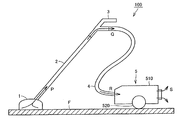
図1は、この発明の集塵装置の一例として電気掃除機の概略的な構成を示す図である。 FIG. 1 is a diagram showing a schematic configuration of a vacuum cleaner as an example of the dust collector of the present invention.
図1に示すように、電気掃除機100の吸込口1は床面F上の塵埃を吸気とともに吸い込む。吸込口1の出口側には真直な円筒状の吸引パイプ2の一端が接続されている。吸引パイプ2の他端には、取手を有し、中途にて若干折れ曲がった接続パイプ3の一端が接続されている。接続パイプ3の他端には、折り曲げ自在のサクションホース4の一端が接続されている。さらに、サクションホース4の他端には、電気掃除機100の本体部5が接続されている。
As shown in FIG. 1, the
本体部5は、略直方体をなす筐体510と、筐体510の側面に回転自在に設けられ、筐体510を床面F上にて移動自在に支持する車輪520を備えており、筐体510内には後述の集塵部、吸引用送風機、電気集塵機、コードリール、吸引用送風機の通電を制御する制御回路等が収容されている。
The
なお、図1においては、塵埃を含んだ気流の流れが矢印で示されている。矢印Pで示すように吸込口1から流入した気流は、吸引パイプ2を通じて、矢印Qで示すように接続パイプ3、サクションホース4の順に吸引経路を流れた後、矢印Rで示すように本体部5内に吸引されて塵埃を除去され、モータを冷却した後に矢印Sで示すように本体部5の外部へ排気される。吸込口1、吸引パイプ2、接続パイプ3およびサクションホース4は、塵埃を含む空気を本体部5の外から内部に流入するための流通路の一部を構成する。
In addition, in FIG. 1, the flow of the airflow containing dust is shown by the arrow. The airflow flowing in from the
集塵部としては、集塵袋方式とサイクロン方式が知られている。 As the dust collection unit, a dust bag method and a cyclone method are known.
集塵部としてサイクロン集塵部を備えた電気掃除機においては、掃除機本体内のサイクロン集塵部による遠心分離によって塵埃を分離捕集し、塵埃が捕集され、清浄になった空気を掃除機本体外部へ排気する。また、サイクロン集塵部は、外径が数μm未満の塵埃に対しては原理的に集塵効率が低下するため、微細な塵埃は捕集されずに排出される。そのため、吸引用送風機の一例であるブラシモータに塵埃が入り込むのを防止するための高性能集塵フィルタをブラシモータの上流に配置している。 In a vacuum cleaner equipped with a cyclone dust collecting part as a dust collecting part, the dust is separated and collected by centrifugal separation by the cyclone dust collecting part in the vacuum cleaner body, and the dust is collected and cleaned. Exhaust outside the machine. Further, since the dust collection efficiency of the cyclone dust collecting portion is reduced in principle for dust having an outer diameter of less than several μm, fine dust is discharged without being collected. Therefore, a high-performance dust collection filter for preventing dust from entering a brush motor, which is an example of a suction blower, is disposed upstream of the brush motor.
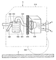
図2は、図1に示す電気掃除機がサイクロン式電気掃除機である場合の本体部の構成を模式的に示す図である。 FIG. 2 is a diagram schematically showing the configuration of the main body when the vacuum cleaner shown in FIG. 1 is a cyclonic vacuum cleaner.
図2に示すように、サイクロン式電気掃除機では、筐体510内には、吸引用送風機の一例であるブラシモータ部530と、ブラシモータ部530の上流側に配置されたHEPAフィルタ540と、集塵部の一例であるサイクロン集塵部550とが配置されている。ブラシモータ部530は、流通路の一部を構成するサクションホース4に連通するように接続され、筐体内510内に配置されて、サクションホース4を通じる流通路に吸気を発生させる。サイクロン集塵部550は、流通路に配置され、ブラシモータ部530によって発生した吸気から塵埃を分離して捕集する。
As shown in FIG. 2, in the cyclone type vacuum cleaner, in the
サイクロン集塵部550は、集積室551と、集積室551の上流側に配置された入口筒552と、集積室551の下流側に配置された外筒553と、外筒553の下流側に接続された連絡筒554とから構成される。吸引経路としての流通路の一部を構成するサクションホース4は入口筒552に接続されている。外筒553と集積室551の内部の空間は連通するように形成されている。流通路の一部を構成する連絡筒554は、HEPAフィルタ540を介してブラシモータ部530に接続されている。
The cyclone
サイクロン集塵部550に流入した塵埃を含む吸気は、入口筒552から集積室551へ流入する。集積室551へ流入した吸気は、集積室551が円筒形状であるため旋回気流となり、中心軸近傍の強制渦領域とその外周側の準自由渦領域とを形成しながら、その経路構造と重力とにより下向きに流れていく。このとき、遠心力が塵埃に作用するため、例えば外径が3μm以上の塵埃は集積室551の内壁に押し付けられて吸気から分離され、下降する気流に沿って集積室551に集められる。その後、気流は上昇に転じ、外筒553、連絡筒554を通じて、HEPAフィルタ540へ流入する。
The intake air including the dust that has flowed into the cyclone
サイクロン集塵部550は、数μm以上の塵埃に対しては高い捕集効率を有しているが、これ以下の大きさの塵埃の捕集についてはあまり効果的ではない。そのため、HEPAフィルタ540によってサイクロン集塵部550で捕集できない微細な塵埃を捕集する。
The cyclone
この発明の実施の形態では、図2に示すように、サイクロン集塵部550が配置される位置よりも上流側の流通路に、この例では、入口筒552に連通するように水粒子供給部としての水分供給部560が配置されている。この水分供給部560により、サイクロン集塵部550に捕集された塵埃に水分が付加される。水分供給部560は、水を霧状にして平均粒径が50μm以下の水粒子を供給する。この発明の実施の形態の電気掃除機100では、このように限定された粒径の水粒子が水分供給部560により塵埃に付加されることは、発明者が鋭意検討し、以下の実験の結果による知見に基づいてなされるものである。
In the embodiment of the present invention, as shown in FIG. 2, the water particle supply unit communicates with the flow path upstream of the position where the cyclone
図10は、本発明の集塵装置の構成の基礎となる実験結果として、図2に示される電気掃除機の本体部において同量の水分が水分供給部560から供給された場合の供給される水分の平均粒子径[μm]と、外径が0.1〜0.2μm、0.2〜0.3μm、0.3〜0.5μm、0.5〜1.0μmのそれぞれの範囲の微細な塵の粒子がサイクロン集塵部550で捕集される割合との関係を示す図である。横軸は供給する水粒子の平均粒子径を対数表記したものであり、縦軸はサイクロン集塵部550における塵埃の捕集率を無次元化したものである。この実験結果を得るための測定は、JIS C 9802に規定された家庭用電気掃除機の性能測定法に基づいてなされたものである。微細な塵の粒子の数を測定するパーティクルカウンタは、外径が0.1μm以上の粒子の数を測定可能なRION社製の型番KC-18を用いた。
FIG. 10 shows an experimental result that is the basis of the configuration of the dust collector of the present invention. In the case where the same amount of water is supplied from the
図10に示す実験結果から、同量の水分を供給する場合、水分の平均粒子径が小さいほど、サイクロン捕集率が高くなる傾向が得られることがわかる。サブミクロンサイズの塵埃の捕集率は、供給する水分の平均粒子径が小さくなるほど顕著に高まる傾向が得られている。 From the experimental results shown in FIG. 10, it can be seen that when the same amount of water is supplied, the cyclone collection rate tends to increase as the average particle size of the water decreases. The collection rate of submicron-size dust tends to increase remarkably as the average particle diameter of the supplied water decreases.
供給する水分の平均粒子径が50〜10μmの場合、特に0.5μm以上のサブミクロン粒子のサイクロン捕集率が向上しており、サブミクロン粒子のサイクロン捕集率が大きく高まる。 When the average particle diameter of the supplied water is 50 to 10 μm, the cyclone collection rate of submicron particles of 0.5 μm or more is particularly improved, and the cyclone collection rate of submicron particles is greatly increased.
供給する水分の平均粒子径が10μm以下の場合、0.5μm以上の微粒子はもちろんのこと、捕集することが非常に困難な0.5μm以下のサブミクロン粒子のサイクロン捕集率も著しく向上しており、サブミクロン粒子のサイクロン捕集率が著しく高まる。 When the average particle size of the supplied water is 10 μm or less, the cyclone collection rate of submicron particles of 0.5 μm or less, which is very difficult to collect, as well as fine particles of 0.5 μm or more is remarkably improved. The cyclone collection rate of submicron particles is significantly increased.
上記の実験結果は次のように推定される。 The above experimental results are estimated as follows.
供給する水分の平均粒子径がサブミクロンサイズの塵埃に近づくほど、水粒子の質量の大きさも塵埃に近づくため、水粒子に作用する遠心力の大きさも塵埃に近づく。このため、サイクロン集塵部550内において、供給する水分が通る軌道と塵埃が通る軌道が近くなり、塵埃との接触確率が高くなるため、水分による凝集の効果も高くなり、サイクロン捕集率が向上する。
The closer the average particle diameter of the water to be supplied is to sub-micron size dust, the closer the mass of water particles is to dust, and the closer the centrifugal force acting on the water particles is to dust. For this reason, in the cyclone
また、供給する水分の平均粒子径が小さいほど、水分量に対する水の表面積の割合が高くなり、塵埃と水表面との接触確率が高くなるため、水分による凝集の効果も高くなり、サイクロン捕集率が向上する。 In addition, the smaller the average particle size of the supplied water, the higher the ratio of the surface area of the water to the amount of water, and the higher the probability of contact between the dust and the water surface. The rate is improved.
さらに、粉体や微粒子では粒径が小さくなるほど、内部の分子・原子に対する表面の分子・原子の割合が増えてくるため、濡れ・吸着・凝集に表面エネルギーの影響が大きくなる。このため、供給する水分の粒子径が小さいほど、表面エネルギーの影響が大きくなり、サブミクロンサイズの塵埃への濡れ・吸着・凝集効果が高まり、サイクロン捕集率が向上するものと考えられる。 Furthermore, since the ratio of surface molecules / atoms to internal molecules / atoms increases as the particle size of powders and fine particles becomes smaller, the influence of surface energy on wetting / adsorption / aggregation increases. For this reason, it is considered that the smaller the particle size of the supplied water, the greater the influence of surface energy, the higher the effect of wetting, adsorbing and agglomerating with submicron-sized dust, and the improvement of the cyclone collection rate.
さらにまた、微細な塵埃は、付加した水分による液架橋力により凝集が促進される。微細な塵埃は、元々、分子間力やファンデルワールス力等により凝集しやすい性質を有しており、一度水分の助力によって凝集すると、水分が乾燥したとしても分散することはないものと考えられる。 Furthermore, aggregation of fine dust is promoted by a liquid crosslinking force due to the added water. Fine dust originally has the property of easily agglomerating due to intermolecular force, van der Waals force, etc., and once agglomerated with the help of moisture, it is considered that the moisture will not disperse even if dried. .
なお、上記の実験結果は、サイクロン式電気掃除機を用いた場合の結果であるが、遠心力を利用しない、たとえば、集塵袋方式のダイレクト集塵式電気掃除機を用いた場合においても、上記と同様の結果が得られるものと考えられる。 In addition, although the above experimental results are the results when using a cyclone type vacuum cleaner, the centrifugal force is not used, for example, even when using a dust bag type direct dust collecting type vacuum cleaner, It is considered that the same result as above can be obtained.
以上の実験結果に基づいて、この発明の集塵装置の一例である電気掃除機の各実施形態を説明する。 Based on the above experimental result, each embodiment of the vacuum cleaner which is an example of the dust collector of this invention is described.
(実施形態1)
本実施形態においては、図2に示される電気掃除機の本体部において水分供給部560から供給される水分は、平均粒子径10μm以下に霧化された水である。
(Embodiment 1)
In the present embodiment, the water supplied from the
平均粒子径10μm以下の水を噴霧するための方法としては、たとえば、遠心式加湿、ブロア2流体ノズル方式、圧搾空気汎用2流体方式、圧搾空気ドライフォグ用2流体方式などの霧化能力(噴霧量)が2000ミリリットル/時間程度の市販の水噴霧装置を採用すればよい。たとえば、圧搾空気汎用2流体方式で、空気圧が0.3MPa程度の圧縮空気を用いて加圧した水をノズルの小さな穴から空気中に噴霧することによって、水を平均粒子径10μm以下に霧化する。 As a method for spraying water having an average particle diameter of 10 μm or less, for example, atomization ability (spraying) such as centrifugal humidification, blower two-fluid nozzle method, compressed air general-purpose two-fluid method, compressed air dry fog two-fluid method, etc. What is necessary is just to employ | adopt the commercially available water spray apparatus whose quantity is about 2000 milliliters / hour. For example, water is atomized to an average particle size of 10 μm or less by spraying water pressurized with compressed air with a compressed air pressure of about 0.3 MPa into the air through a small hole in the nozzle using a compressed air general-purpose two-fluid system. To do.
本発明の集塵装置の一例である実施形態1の電気掃除機によれば、サブミクロン粒子のサイクロン捕集率が著しく高まる。0.5μm以上の微粒子はもちろんのこと、捕集することが非常に困難な0.5μm以下のサブミクロン粒子のサイクロン捕集率も著しく向上する。これにより、人体に悪影響を及ぼすといわれる幅広い範囲のサブミクロン粒子(特により微細なサブミクロン粒子)の排出量を大幅に抑制でき、さらに健康によいサイクロン式電気掃除機が得られる。
According to the vacuum cleaner of
また、サブミクロン粒子をサイクロン集塵部において捕集できるため、HEPAフィルタへの負担が軽減され、圧力損失の増加に伴う電力消費量の増加がなく、HEPAフィルタの掃除を行う頻度が低下するため、ユーザへの負担が軽減するとともに、メンテナンスの効率を高めることができる。 In addition, since submicron particles can be collected in the cyclone dust collecting section, the burden on the HEPA filter is reduced, there is no increase in power consumption accompanying an increase in pressure loss, and the frequency of cleaning the HEPA filter is reduced. The burden on the user can be reduced, and the maintenance efficiency can be increased.
さらに、供給された水分は平均粒子径10μm以下であるので、運転中に供給された水分は蒸発しやすく、乾燥しやすい。このため、蒸発しやすく乾燥しやすいサイクロン式電気掃除機が得られる。 Furthermore, since the supplied water has an average particle size of 10 μm or less, the water supplied during operation is easily evaporated and easily dried. For this reason, the cyclonic vacuum cleaner which is easy to evaporate and is easy to dry is obtained.
さらにまた、塵埃中の水分は、一定時間の運転の内にある程度乾燥によって除去されていくため、サイクロン集塵部に水分が残留し難く、サイクロン集塵部内で菌の繁殖やカビの発生、異臭が発生するなどの問題を起こし難い湿式サイクロン電気掃除機が得られる。また、塵埃中の水分は、一定時間の運転の内にある程度乾燥によって除去されていくため、サイクロン集塵部に水分が残留し難いので、掃除後に水分を取り除くというメンテナンスを軽減することが可能なサイクロン電気掃除機が得られる。 Furthermore, since moisture in the dust is removed by drying to some extent during a certain period of operation, moisture hardly remains in the cyclone dust collection unit, causing bacterial growth, mold generation, and offensive odor in the cyclone dust collection unit. A wet-type cyclone vacuum cleaner that is unlikely to cause problems such as the occurrence of water is obtained. In addition, since moisture in the dust is removed by drying to some extent during operation for a certain period of time, it is difficult for moisture to remain in the cyclone dust collection part, so maintenance that removes moisture after cleaning can be reduced. A cyclone vacuum cleaner is obtained.
(実施形態2)
本発明の実施形態2では、図2に示される電気掃除機の本体部の構成において、供給される水を平均粒子径10μm以下で、かつ、最大粒子径50μm以下に霧化し、いわゆるドライフォグといわれるサイズの水を供給する。
(Embodiment 2)
In
平均粒子径10μm以下で、かつ、最大粒子径50μm以下の水を噴霧するための方法としては、たとえば、圧搾空気ドライフォグ用2流体方式などの霧化能力(噴霧量)が2000ミリリットル/時間程度の市販の水噴霧装置を採用すればよい。たとえば、圧搾空気ドライフォグ用2流体方式で、空気圧が0.3MPa程度の圧縮空気を用いて加圧した水をノズルの小さな穴から空気中に噴霧することによって、水を平均粒子径10μm以下で、かつ、最大粒子径50μm以下に霧化する。その他の構成は、実施形態1と同様である。 As a method for spraying water having an average particle size of 10 μm or less and a maximum particle size of 50 μm or less, for example, the atomization capability (spray amount) of a two-fluid system for compressed air dry fog is about 2000 ml / hour. A commercially available water spray device may be employed. For example, in a two-fluid system for compressed air dry fog, water that is pressurized with compressed air having an air pressure of about 0.3 MPa is sprayed into the air from a small hole in the nozzle, so that the water has an average particle size of 10 μm or less. And atomized to a maximum particle size of 50 μm or less. Other configurations are the same as those of the first embodiment.
この場合、平均粒子径10μm以下かつ最大粒子径50μm以下に霧化した水を供給することにより、水粒子はサイクロン集塵部550の内壁等の塵埃が通過する経路内を濡らさない。
In this case, by supplying water atomized to an average particle size of 10 μm or less and a maximum particle size of 50 μm or less, the water particles do not get wet in the path through which dust passes, such as the inner wall of the cyclone
ここで、「濡れ」とは固体表面上に接触した液体の広がりを意味する。「濡れる」過程では、固体の表面が液体に接触し、固液の界面を生成するので、これらの接触面積と付着エネルギー、表・界面自由エネルギーや接触角等様々な要因が「濡れ」に関わってくる。水の場合、弾性率を一定とすると、粒子径が小さくなるほど、接触面積と付着エネルギーが小さくなり、濡れ難くなる。 Here, “wetting” means the spread of the liquid in contact with the solid surface. In the “wetting” process, the surface of the solid comes into contact with the liquid and creates a solid-liquid interface, so various factors such as contact area and adhesion energy, surface / interface free energy and contact angle are related to “wetting”. Come. In the case of water, if the elastic modulus is constant, the smaller the particle diameter, the smaller the contact area and adhesion energy, and the less likely it is to get wet.
ドライフォグ領域の水の場合、水の粒子径が非常に小さいため、接触面積と付着エネルギーが非常に小さく、水粒子は固体表面に付着しないため、固体表面を濡らさない。このため、水粒子はサイクロン集塵部550の内壁等の塵埃が通過する経路内を濡らさない。
In the case of water in the dry fog region, since the particle size of water is very small, the contact area and the adhesion energy are very small, and the water particles do not adhere to the solid surface, so that the solid surface is not wetted. For this reason, the water particles do not get wet in the path through which dust passes, such as the inner wall of the cyclone
しかしながら、粉体や微粒子では粒径が小さくなるほど、内部の分子・原子に対する表面の分子・原子の割合が増えてくるため、濡れ・吸着・凝集に表面エネルギーの影響が大きくなる。このため、ドライフォグ領域の水とサブミクロン領域の塵の粒子との接触の場合、接触面積と付着エネルギー、表・界面自由エネルギーや接触角等よりも、表面エネルギーの影響が支配的となり、濡れ・吸着・凝集が起こる。 However, in powder and fine particles, the smaller the particle size, the greater the ratio of surface molecules / atoms to internal molecules / atoms, so that the influence of surface energy on wetting / adsorption / aggregation increases. For this reason, in the case of contact between water in the dry fog region and dust particles in the submicron region, the influence of the surface energy is more dominant than the contact area, adhesion energy, surface / interface free energy, contact angle, etc.・ Adsorption and aggregation occur.
本発明の実施形態2の電気掃除機によれば、水粒子はサイクロン集塵部550の内壁等の塵埃が通過する経路内を濡らさないため、塵埃のみに効率よく水分を付加することができ、実施形態1よりもさらに凝集効果が高まり、サブミクロンサイズの粒子の捕集効率がさらに高まる。
According to the vacuum cleaner of
また、供給した水分によってサイクロン集塵部の内壁等の塵埃が通過する経路内が濡れることがないため、塵埃が壁面等へ付着してスラリー状になる等の問題が発生しない。そのため、非常に清潔な湿式サイクロン電気掃除機が得られる。 Further, since the inside of the path through which the dust passes, such as the inner wall of the cyclone dust collecting portion, is not wetted by the supplied water, there is no problem of dust adhering to the wall surface or the like and becoming a slurry. Therefore, a very clean wet cyclone vacuum cleaner is obtained.
さらに、供給した水分によってサイクロン集塵部の内壁等の塵埃が通過する経路内が濡れることがないので、無駄なく塵埃を凝集させるための水分を供給できる。このため、供給水分量を節約することができる。これにより、水の入れ替え等の回数が減るなど、メンテナンスに必要な時間を節約することが可能な湿式サイクロン電気掃除機が得られる。 Furthermore, since the inside of the path | route where dust passes, such as the inner wall of a cyclone dust collection part, does not get wet with the supplied water | moisture content, the water | moisture content for agglomerating dust can be supplied without waste. For this reason, the amount of supplied water can be saved. Thereby, the wet cyclone vacuum cleaner which can save the time required for maintenance, such as reducing the frequency | count of replacement | exchange of water etc., is obtained.
さらにまた、供給した水分によってサイクロン集塵部550の内壁等の塵埃が通過する経路内が濡れることがないので、塵埃の水分は一定時間の運転の内にさらに乾燥しやすくなり、サイクロン集塵部550に水分がさらに残留し難く、サイクロン集塵部550内で菌の繁殖やカビの発生、異臭が発生するなどの問題をさらに起こし難い湿式サイクロン電気掃除機が得られる。
Furthermore, since the inside of the path through which the dust passes, such as the inner wall of the cyclone
(実施形態3)
本発明の実施形態3では、図2に示される電気掃除機の本体部5において水分供給部560から平均粒子径50μm以下の水を供給する。
(Embodiment 3)
In Embodiment 3 of this invention, the water of the average particle diameter of 50 micrometers or less is supplied from the water | moisture-
平均粒子径50μm以下の水を噴霧するための方法としては、たとえば、遠心式加湿、ブロア2流体ノズル方式、圧搾空気汎用2流体方式、圧搾空気ドライフォグ用2流体方式などの霧化能力(噴霧量)が2000ミリリットル/時間程度の市販の噴霧装置を採用すればよい。たとえば、圧搾空気汎用2流体方式で、空気圧が0.3MPa程度の圧縮空気を用いて加圧した水をノズルの小さな穴から空気中に噴霧することによって、水を平均粒子径50μm以下に霧化する。その他の構成は、実施形態1と同様である。 As a method for spraying water having an average particle size of 50 μm or less, for example, atomization ability (spraying) such as centrifugal humidification, blower two-fluid nozzle method, compressed air general-purpose two-fluid method, compressed air dry fog two-fluid method, etc. What is necessary is just to employ | adopt the commercially available spraying apparatus whose quantity is about 2000 milliliters / hour. For example, water is atomized to an average particle diameter of 50 μm or less by spraying water pressurized with compressed air with an air pressure of about 0.3 MPa into the air through a small hole in the nozzle using a compressed air general-purpose two-fluid system. To do. Other configurations are the same as those of the first embodiment.
この場合、実施形態1よりも、霧化する水分の平均粒子径が大きいため、噴霧装置は、その構成が簡単なものになり、かつ安価になる。 In this case, since the average particle diameter of the water to be atomized is larger than that of the first embodiment, the spray device has a simple configuration and is inexpensive.
本発明の実施形態3の電気掃除機によれば、サブミクロン粒子のサイクロン捕集率が高まり、特に0.5μm以上のサブミクロン粒子のサイクロン捕集率が向上する。 According to the vacuum cleaner of Embodiment 3 of the present invention, the cyclone collection rate of submicron particles is increased, and in particular, the cyclone collection rate of submicron particles of 0.5 μm or more is improved.
また、安価で実施が容易な構成で実施形態1に近い効果を得ることができる。外径が0.5μm以上のサブミクロン粒子のサイクロン捕集率において実施形態1とほぼ同等の効果を達成できる。 In addition, an effect close to that of the first embodiment can be obtained with an inexpensive and easy-to-implement configuration. In the cyclone collection rate of sub-micron particles having an outer diameter of 0.5 μm or more, substantially the same effect as in the first embodiment can be achieved.
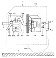
(実施形態4)
図3は、本発明の実施形態4に係る電気掃除機の本体部の構成を模式的に示す図である。
(Embodiment 4)
FIG. 3 is a diagram schematically showing the configuration of the main body of the electric vacuum cleaner according to Embodiment 4 of the present invention.
図3に示すように、本実施形態は、水分供給部560により、サイクロン集塵部550に捕集された塵埃に水分が付加される。塵埃量検知部570が、集塵部としてのサイクロン集塵部550に配置され、塵埃の量を検知する。サイクロン集塵部550に付加される水分量は、塵埃量検知部570により推定された塵埃量から算出される水分量である。その他の構成は、実施形態1と同様である。
As shown in FIG. 3, in the present embodiment, moisture is added to the dust collected by the cyclone
塵埃量検知部570は、サイクロン集塵部550内に捕集されたゴミ容積を検出し、ゴミ容積から塵埃量を推定する。具体的には、一例として、サイクロン集塵部550においてダストカップの底面から集積された塵埃の高さを、赤外線発光素子と受光部とからなるセンサによって検出し、その検出された塵埃の高さと、ダストカップの容積とに基づいて塵埃量(重量)を算出する。
The
水分量は、以下の実験結果に基づいて算出する。 The water content is calculated based on the following experimental results.
塵埃1g当たり1ミリリットルの水分を付加した場合、流量1.5m3/minの空気を7分間、集塵部に流すこと、すなわち、10.5m3の空気で十分に乾燥させること(乾燥率[%]=(水分付加前の塵埃重量)/(水分付加後の塵埃重量)=90[%]の場合に相当する)ができた。この結果に基づいて、上記で算出された塵埃量に対して、十分に乾燥可能な水分の付加量を算出する。 When 1 milliliter of water is added per 1 g of dust, air having a flow rate of 1.5 m 3 / min is allowed to flow through the dust collecting part for 7 minutes, that is, sufficiently dried with 10.5 m 3 air (drying rate [ %] = (Weight of dust before adding water) / (weight of dust after adding water) = 90 [%]. Based on this result, the amount of moisture that can be sufficiently dried is calculated with respect to the amount of dust calculated above.
このようにして塵埃量から算出される水分量は、付加した水分を電気掃除機内を流れる気流により一定時間(一回の掃除あたりの電気掃除機使用時間である7分以内)で乾燥することができ、また塵埃を水分により凝集することができる最適な水分量である。 Thus, the amount of moisture calculated from the amount of dust can be dried for a certain period of time (within 7 minutes, which is the duration of use of the vacuum cleaner per cleaning) by the airflow flowing through the vacuum cleaner. This is the optimum amount of moisture that can be aggregated with moisture.
この実施形態によれば、水分供給部560より供給される水分が塵埃量に応じた最適な水分量であるので、より短い乾燥期間で塵埃の乾燥を行うことができる。
According to this embodiment, since the moisture supplied from the
また、水分供給部560より供給される水分が塵埃量に応じた最適な水分量であるため、必要以上の水分を貯水する必要がない。このため、電気掃除機本体の重量が重くなることはなく、掃除を行う際に、取り回しがし難くなるなどの操作性の悪化がなく、ユーザへの負担も少ない湿式サイクロン電気掃除機が得られる。
In addition, since the water supplied from the
さらに、水分供給部560より供給される水分が塵埃量に応じた最適な水分量であるため、水分を供給する水分供給部560に常に貯水しておく必要がない。このため、多量の水が水分供給部560に余ることがなく、水を無駄にすることなく、水道代の増加によるユーザの経済的負担、ひいては地球環境の悪化を防ぐことができる。
Furthermore, since the water supplied from the
(実施形態5)
図4は、本発明の実施形態5に係る電気掃除機の本体部の構成を模式的に示す図である。
(Embodiment 5)
FIG. 4 is a diagram schematically showing the configuration of the main body of the electric vacuum cleaner according to
図4に示すように、本実施形態では、塵埃量検知部570が集塵部としてのサイクロン集塵部550よりも上流側の流通路である吸引経路、この例ではサクションホース4に配置されている。その他の構成は、実施形態1と同様である。
As shown in FIG. 4, in this embodiment, the dust
塵埃量検知部570は、例えば、赤外線発光素子と受光部からなり、サイクロン集塵部550より上流の吸引経路を通過する気流に含まれる塵埃を検出する。サンプリング時間ごとの塵埃検出の出力を積算することによって、吸引した塵埃の量を推定する。サイクロン集塵部550に付加される水分量は、塵埃量検知部570により推定された塵埃量から算出される水分量である。塵埃の量と水分量の算出方法は、実施形態4と同様である。
The dust
なお、上述した塵埃量検知部570は赤外線発光素子と受光部とからなる構成に限定されることなく、例えば、赤外線レーザなどを用いた構成を採用してもよい。
In addition, the dust
この実施形態によれば、吸引経路を通過する気流に含まれる塵埃を検出することにより、吸引した塵埃量を推定することができる。実施形態4と同様の効果が得られる。また、塵埃量検知部570は、サイクロン集塵部550内に配置されていないので、サイクロン集塵部550内に塵埃検知部570を配置する実施形態4の場合に比べて、気流が複雑に流れていないので、塵埃量検知部570にゴミが詰まる等による精度低下や、塵埃推定量の誤差の拡大、ゴミが詰まった場合のメンテナンス等を行う必要がない。
According to this embodiment, the amount of sucked dust can be estimated by detecting dust contained in the airflow passing through the suction path. The same effect as in the fourth embodiment can be obtained. Further, since the dust
(実施形態6)
図5は、本発明の実施形態6に係る電気掃除機の本体部の構成を模式的に示す図である。
(Embodiment 6)
FIG. 5 is a diagram schematically illustrating the configuration of the main body of the electric vacuum cleaner according to the sixth embodiment of the present invention.
図5に示すように、この実施形態では、乾燥状態検知部580は、集塵部としてのサイクロン集塵部550が配置される位置よりも下流側に配置され、気流に含まれる水分量を検出することにより、乾燥状態を検知する。その他の構成は、実施形態1と同様である。
As shown in FIG. 5, in this embodiment, the dry
この実施形態によれば、水分供給部560から供給される水分は、塵埃の量に基づいて算出する必要はないので、塵埃量検知部が不要である。
According to this embodiment, the moisture supplied from the
乾燥状態検知部580は、例えば、湿度センサを用いて構成され、外部の湿度とサイクロン集塵部550の下流側の気流の湿度とを比較することによって、乾燥状態を検知する。そして、水分供給部560が水をサイクロン集塵部550に集積した塵埃に供給した後、乾燥状態検知部580が乾燥状態を検知するまでの間、水分供給部560による水の供給を停止する。
The dry
これにより、サイクロン集塵部550内に水分が残留しないとともに、塵埃と、サイクロン集塵部550等の塵埃が通過する経路内とを乾燥することができる。また、乾燥状態検知部580の出力により、乾燥時間を制御することができる。
Accordingly, moisture does not remain in the cyclone
なお、乾燥状態検知部580は、湿度センサを用いた構成に限定されず、サーミスタや、気流中の水分量を検出することが可能なその他の装置で構成されてもよい。
In addition, the dry
乾燥状態検知部580は、本実施形態のように配置される場合に限定されるものではなく、サイクロン集塵部550よりも下流側であれば、モータよりも上流側に配置されてもよい。
The dry
この実施形態によれば、塵埃と、サイクロン集塵部550等の塵埃が通過する経路内を確実に乾燥することができるため、サイクロン集塵部550に水分が残留せず、サイクロン集塵部550内で菌の繁殖やカビの発生、異臭が発生するなどの問題を起こさない湿式サイクロン電気掃除機が得られる。
According to this embodiment, since the inside of the path through which the dust and the dust such as the
また、掃除後にサイクロン集塵部550に水が残留しないため、掃除後に水分を取り除くというメンテナンスを必要としないサイクロン電気掃除機が得られる。
Moreover, since water does not remain in the cyclone
さらに、塵埃量検知部を構成する赤外線発光デバイスなどよりも、乾燥状態検知部を構成する湿度センサなどの方が安価であり、本実施形態では塵埃量検知部が必要でないため、製造コストを抑えることができる。 In addition, the humidity sensor that constitutes the dry state detection unit is cheaper than the infrared light emitting device that constitutes the dust amount detection unit, and the dust amount detection unit is not necessary in this embodiment, thereby reducing the manufacturing cost. be able to.
さらにまた、乾燥状態検知部の出力により、乾燥時間を制御することができるため、より効率的に、より精度よく、水分供給後の乾燥を行うことができる。 Furthermore, since the drying time can be controlled by the output of the dry state detection unit, the drying after the moisture supply can be performed more efficiently and more accurately.
(実施形態7)
図6は、本発明の実施形態7に係る電気掃除機の本体部の構成を模式的に示す図である。
(Embodiment 7)
FIG. 6 is a diagram schematically illustrating the configuration of the main body of the electric vacuum cleaner according to the seventh embodiment of the present invention.
図6に示すように、この実施形態では、塵埃量検知部570をサイクロン集塵部550内に配置し、乾燥状態検知部580をサイクロン集塵部550が配置される位置よりも下流側に配置する。その他の構成は、実施形態1と同様である。塵埃量検知部570の機能は実施形態4で説明したものと同様であり、乾燥状態検知部580の機能は実施形態6で説明したものと同様である。
As shown in FIG. 6, in this embodiment, the dust
この実施形態によれば、供給された水分は、塵埃量から算出された最適水分量がサイクロン集塵部550に供給され、乾燥状態検知部580により、水分供給後に気流の乾燥状態を検知することができるため、より効率的に、より精度よく、水分供給後の乾燥を行うことができる。すなわち、実施形態6で達成される作用効果をさらに効果的に達成することができる。
According to this embodiment, the supplied water is supplied to the cyclone
(実施形態8)
図7は、本発明の実施形態8に係る電気掃除機の本体部の構成を模式的に示す図である。
(Embodiment 8)
FIG. 7 is a diagram schematically illustrating the configuration of the main body of the electric vacuum cleaner according to the eighth embodiment of the present invention.
図7に示すように、塵埃量検知部570をサイクロン集塵部550が配置される位置よりも上流側の流通路に配置し、乾燥状態検知部580をサイクロン集塵部550が配置される位置よりも下流側に配置する。その他の構成は、実施形態1と同様である。塵埃量検知部570の機能は実施形態4で説明したものと同様であり、乾燥状態検知部580の機能は実施形態6で説明したものと同様である。
As shown in FIG. 7, the dust
この実施形態によれば、塵埃量から算出された最適水分量がサイクロン集塵部550に供給され、乾燥状態検知部580により、水分供給後に気流の乾燥状態を検知することができるため、より効率的に、より精度よく、水分供給後の乾燥を行うことができる。
According to this embodiment, the optimum moisture amount calculated from the dust amount is supplied to the cyclone
また、実施形態7の場合のようにサイクロン集塵部550内に塵埃検知部570を配置する場合は、気流が複雑に流れているため、塵埃量検知部570にゴミが詰まる等による精度の低下や、塵埃推定量の誤差の拡大、ゴミが詰まった場合のメンテナンス等を行う必要があるが、実施形態8によれば、これらの問題を解消することができ、実施形態7よりも乾燥効果をさらに高めることができる。
Further, when the
(実施形態9)
図8は、本発明の実施形態9に係る電気掃除機の本体部の構成を模式的に示す図である。
(Embodiment 9)
FIG. 8 is a diagram schematically illustrating the configuration of the main body of the electric vacuum cleaner according to the ninth embodiment of the present invention.
図8に示すように、サイクロン集塵部550に加えて、HEPAフィルタ591を含む集塵部590がモータの下流側に配置される。また、乾燥状態検知部580をサイクロン集塵部550が配置される位置よりも下流側に配置する。その他の構成は、実施形態8と同様である。
As shown in FIG. 8, in addition to the cyclone
この実施形態においては、集塵部590が、モータの下流にあるため、モータの熱によって温められた気流によって乾燥される。また、乾燥状態検知部580は、サイクロン集塵部550を流通する空気の乾燥状態も合わせて検知を行う。
In this embodiment, since the
この実施形態によれば、モータの熱によって温められた気流によって乾燥を行うため、乾燥の効率が飛躍的に高まる。 According to this embodiment, since the drying is performed by the air current warmed by the heat of the motor, the efficiency of drying is dramatically increased.
(実施形態10)
図9は、本発明の一つの実施形態として電気掃除機の本体部に適用される水分供給部の構成を模式的に示す図である。
(Embodiment 10)
FIG. 9 is a diagram schematically illustrating a configuration of a moisture supply unit applied to the main body of the electric vacuum cleaner as one embodiment of the present invention.
図9に示すように、水分供給部560は、水分結露部561と、水分結露部561で得られた水分を流通させる水分流通路562と、水分を計量する水分計量部563と、水分供給管565と、水分供給管565の内部に配置された弁564と、水分を霧化する霧化部566とから構成される。
As shown in FIG. 9, the
水分結露部561は、電子冷却、例えばペルチェ素子等を用いることにより、空気を冷却し、空気中の水分を結露し、水分を取得する。水分結露部561によって得られた水分は、水分計量部563によって計量され、弁564が開くことにより、供給される水分量を制御し、霧化部566へ水分を供給する。霧化部566は、図2に示すように入口筒552に連通するように接続される。
The moisture
水分計量部563は、例えば、赤外線発光素子と受光部からなるセンサによって水の高さを検出し、水分容積を算出する。
For example, the
水分計量部563で算出された水分量が、実施形態4にて算出した最適水分量に達すると、弁564を開放するように構成されている。
The
なお、水分供給の手段としては、モータの吸気圧力を利用してもよく、あるいは、例えば、マイクロポンプ等によって構成された、少量の水分を供給するための装置を用いて、実施形態4にて算出された最適水分量を供給してもよい。 In addition, as a means for supplying water, the intake pressure of the motor may be used, or, for example, using a device for supplying a small amount of water configured by a micropump or the like in the fourth embodiment. You may supply the calculated optimal moisture content.
上記のように構成された水分供給部560を用いることにより、ユーザが給水することなく、サイクロン集塵部に供給する水分を得ることができる。
By using the
また、水分を供給する水分供給部に常に貯水しておく必要がないため、多量の水が水分供給部に余ることがなく、菌の繁殖やカビの発生、異臭の発生を引き起こすことがない湿式サイクロン電気掃除機が得られる。 In addition, since it is not necessary to always store water in the moisture supply section that supplies moisture, a large amount of water does not remain in the moisture supply section, and wet processing that does not cause bacterial growth, generation of mold, and generation of off-flavors A cyclone vacuum cleaner is obtained.
さらに、水分を供給する水分供給部に常に貯水しておく必要がないことにより、貯水部分を取り付ける必要がないため、電気掃除機本体の重量が重くなることはなく、掃除を行う際に、取り回しがし難くなるなどの操作性の悪化がなく、ユーザへの負担も少ない湿式サイクロン電気掃除機が得られる。また、製造コストを抑えることができる。 In addition, since it is not necessary to always store water in the water supply part that supplies water, there is no need to attach a water storage part, so the weight of the vacuum cleaner body does not increase, and it is handled when cleaning. Thus, a wet-type cyclonic vacuum cleaner that does not deteriorate the operability such as being difficult to remove and has a low burden on the user can be obtained. Moreover, manufacturing cost can be suppressed.
さらにまた、ユーザが水を供給する必要がないため、掃除をするたびに、水分供給部に水を入れ、掃除後に水を捨てるという手間のかからない湿式サイクロン電気掃除機が得られる。水を給水する必要がないため、水を無駄にすることなく、水道代の増加によるユーザの経済負担、ひいては地球環境の悪化を防ぐことができる。 Furthermore, since there is no need for the user to supply water, a time-saving wet-type cyclonic vacuum cleaner can be obtained in which water is put into the moisture supply unit every time cleaning is performed and the water is discarded after cleaning. Since there is no need to supply water, it is possible to prevent the user from burdening the economy due to an increase in water bills, and thus the deterioration of the global environment, without wasting water.
(実施形態11)
実施形態11は、本発明の構成が、集塵装置の一例として空気清浄機に適用された場合の作用効果について説明する。
(Embodiment 11)
Embodiment 11 demonstrates the effect when the structure of this invention is applied to an air cleaner as an example of a dust collector.
最大粒子径50μm以下かつ平均粒子径10μm以下に霧化された水を供給することにより、高性能集塵フィルタにおいても完全には捕集できないサブミクロン粒子のサイクロン捕集率が著しく高まる。特に捕集が非常に困難な0.5μm以下の領域のサブミクロン粒子の捕集率が著しく向上する。これにより、人体に悪影響を及ぼすといわれるサブミクロン粒子を大幅に捕集でき、さらに健康によい空気清浄機が得られる。 By supplying water atomized to a maximum particle size of 50 μm or less and an average particle size of 10 μm or less, the cyclone collection rate of submicron particles that cannot be completely collected even in a high-performance dust collection filter is remarkably increased. In particular, the collection rate of submicron particles in the region of 0.5 μm or less which is very difficult to collect is remarkably improved. As a result, submicron particles, which are said to have an adverse effect on the human body, can be largely collected, and a healthier air cleaner can be obtained.
微細な塵埃は、付加した水分による液架橋力により凝集が促進される。微細な塵埃は、元々、分子間力やファンデルワールス力等により凝集しやすい性質を有しており、一度水分の助力によって凝集すると、水分が乾燥したとしても分散することはないと考えられる。これにより、高性能集塵フィルタにおいても完全には捕集できない微細な塵埃の捕集率の高い空気清浄機が得られる。 Aggregation of fine dust is promoted by the liquid crosslinking force caused by the added water. Fine dust originally has the property of easily agglomerating due to intermolecular force, van der Waals force, etc., and once agglomerated by the assistance of moisture, it is considered that the moisture does not disperse even if dried. Thereby, an air cleaner having a high collection rate of fine dust that cannot be completely collected even by a high-performance dust collection filter can be obtained.
また、上記の効果により、集塵部に捕集された塵埃を取り除く場合に起こる再飛散を抑制することができる。 In addition, the above-described effect can suppress re-scattering that occurs when dust collected in the dust collection unit is removed.
綿ゴミのような比較的比重の軽いゴミの場合、水分の付加により圧縮が促進されるため、より多くの綿ゴミを集塵部に捕集することができる。一度、水分の助力によって圧縮された綿ゴミは、水分が乾燥しても、圧縮された状態がある程度保持されると考えられる。これにより、集塵部により多くの塵埃を捕集することができる空気清浄機が得られる。 In the case of dust having a relatively low specific gravity such as cotton dust, compression is promoted by the addition of moisture, so that more cotton dust can be collected in the dust collecting portion. It is considered that the cotton dust once compressed with the help of moisture retains the compressed state to some extent even when the moisture is dried. Thereby, the air cleaner which can collect many dusts by a dust collection part is obtained.
上述した電気掃除機の実施形態のように、供給される水分を塵埃量から算出された最適水分量にすることにより、供給された水分は一定時間内に乾燥によって除去されるため、集塵部に水分が残留せず、集塵部内で菌の繁殖やカビの発生、異臭が発生するなどの問題を起こさない空気清浄機が得られる。 As in the embodiment of the vacuum cleaner described above, the supplied moisture is removed by drying within a certain time by setting the supplied moisture to the optimum moisture amount calculated from the dust amount. Thus, an air purifier can be obtained in which moisture does not remain in the dust collecting section and does not cause problems such as the growth of fungi, the generation of mold, and the generation of off-flavors.
また、供給される水分を塵埃量から算出された最適水分量にすることにより、供給された水分は、一定時間内に空気清浄機内を流れる気流によって乾燥されるため、電子加熱等の加熱方法を必要としない。このため、電力消費量の増加がなく、電気代の増加などのユーザへの負担、ひいては地球環境の悪化を引き起こすことのない、経済的で環境にもやさしい空気清浄機が得られる。 In addition, by making the supplied moisture the optimum moisture amount calculated from the amount of dust, the supplied moisture is dried by the airflow flowing in the air purifier within a certain time, so a heating method such as electronic heating is used. do not need. For this reason, there is no increase in power consumption, and it is possible to obtain an economical and environmentally friendly air purifier that does not cause a burden on the user such as an increase in electricity bills, and thus does not deteriorate the global environment.
さらに、供給された水分は、一定時間内に空気清浄機内を流れる気流によって乾燥されるため、電子加熱等の加熱方法を必要としないので、電子加熱等で加熱を行う場合に発生していた問題が解消される。すなわち、加熱された気流がモータ部分を通過するためにモータの十分な冷却が行われないことによる問題として、モータ性能の低下による吸い込み仕事率の低下に伴う掃除効率の低下、それによる電気代の増加などのユーザへの負担、さらにモータ寿命の短縮を引き起こす等の問題を引き起こさない空気清浄機が得られる。 Furthermore, since the supplied moisture is dried by the airflow flowing in the air purifier within a certain time, a heating method such as electronic heating is not required, and thus a problem that has occurred when heating is performed by electronic heating or the like. Is resolved. That is, as the problem that the motor is not sufficiently cooled because the heated airflow passes through the motor portion, the cleaning efficiency is reduced due to the reduction of the suction work rate due to the reduction of the motor performance, and the electricity cost is thereby reduced. It is possible to obtain an air cleaner that does not cause problems such as a burden on the user such as an increase and a reduction in motor life.
以上の実施形態では、本発明の集塵装置が適用される例として、電気掃除機、空気清浄機について説明したが、少なくとも、送風機を用いて吸気から塵埃を分離する集塵装置を備えたものであれば、種々の機器に本発明の集塵装置を適用することができる。また、本発明の集塵装置は、サイクロン式電気掃除機だけでなく、集塵袋式電気掃除機にも適用することができ、上述した作用効果と同様の作用効果を達成することができる。 In the above embodiment, the vacuum cleaner and the air cleaner have been described as examples to which the dust collector of the present invention is applied, but at least a dust collector that separates dust from the intake air using a blower is provided. If so, the dust collector of the present invention can be applied to various devices. Moreover, the dust collector of this invention can be applied not only to a cyclone type vacuum cleaner but also to a dust bag type vacuum cleaner, and can achieve the same effects as the above-described effects.
以上に開示された実施の形態はすべての点で例示であって制限的なものではないと考慮されるべきである。本発明の範囲は、以上の実施の形態ではなく、特許請求の範囲によって示され、特許請求の範囲と均等の意味および範囲内でのすべての修正と変形を含むものである。 The embodiment disclosed above should be considered as illustrative in all points and not restrictive. The scope of the present invention is shown not by the above embodiments but by the scope of claims, and includes all modifications and variations within the meaning and scope equivalent to the scope of claims.
100:電気掃除機、4:サクションホース、5:本体部、510:筐体、530:ブラシモータ部、550:サイクロン集塵部、560:水分供給部、561:水分結露部、570:塵埃量検知部、580:乾燥状態検知部。 100: Vacuum cleaner, 4: Suction hose, 5: Main body part, 510: Housing, 530: Brush motor part, 550: Cyclone dust collecting part, 560: Water supply part, 561: Water condensation part, 570: Dust amount Detection unit, 580: Drying state detection unit.
Claims (3)
塵埃を含む空気を前記本体の外から内部に流入させるための流通路と、
前記流通路に接続するように前記本体内に配置され、前記流通路に吸気を発生させる送風機と、
前記流通路に配置され、前記送風機によって発生した吸気から塵埃を分離して捕集するサイクロン集塵部と、
水を霧状にして、前記サイクロン集塵部が配置される位置よりも上流側の前記流通路に、サブミクロン粒子のサイクロン捕集率を高めるために平均粒子径が10μm以下の水粒子を供給する水粒子供給部とを備える、集塵装置。 The body,
A flow path for allowing air containing dust to flow from the outside to the inside of the main body;
A blower disposed in the main body so as to be connected to the flow passage, and generating intake air in the flow passage;
A cyclone dust collecting part that is arranged in the flow passage and separates and collects dust from intake air generated by the blower;
In order to increase the cyclone collection rate of submicron particles , water particles having an average particle size of 10 μm or less are formed in the water passage in the upstream side of the position where the cyclone dust collecting portion is arranged. A dust collector comprising a water particle supply unit for supplying.
前記塵埃量検知部は、検知された塵埃の量に基づいて、前記水粒子供給部が供給する水の量を決定する、請求項1に記載の集塵装置。 It further includes a dust amount detection unit for detecting the amount of dust,
The dust collection device according to claim 1, wherein the dust amount detection unit determines an amount of water supplied by the water particle supply unit based on the detected amount of dust.
前記水粒子供給部が水粒子を供給した後、前記乾燥状態検知部が乾燥状態を検知するまでの間、前記水粒子供給部による水粒子の供給を停止する、請求項1または請求項2に記載の集塵装置。 It further includes a dry state detection unit that is disposed downstream of the position where the dust collection unit is disposed and detects the dry state by detecting the amount of moisture contained in the airflow,
After the water particle feeding section is supplied with water particles, until the dryness detecting unit detects the dry state to stop the supply of the water particles by the water particle supply section, to claim 1 or claim 2 The dust collector described.
Priority Applications (1)
| Application Number | Priority Date | Filing Date | Title |
|---|---|---|---|
| JP2007206416A JP4954825B2 (en) | 2007-08-08 | 2007-08-08 | Dust collector |
Applications Claiming Priority (1)
| Application Number | Priority Date | Filing Date | Title |
|---|---|---|---|
| JP2007206416A JP4954825B2 (en) | 2007-08-08 | 2007-08-08 | Dust collector |
Publications (3)
| Publication Number | Publication Date |
|---|---|
| JP2009039253A JP2009039253A (en) | 2009-02-26 |
| JP2009039253A5 JP2009039253A5 (en) | 2009-12-03 |
| JP4954825B2 true JP4954825B2 (en) | 2012-06-20 |
Family
ID=40440676
Family Applications (1)
| Application Number | Title | Priority Date | Filing Date |
|---|---|---|---|
| JP2007206416A Expired - Fee Related JP4954825B2 (en) | 2007-08-08 | 2007-08-08 | Dust collector |
Country Status (1)
| Country | Link |
|---|---|
| JP (1) | JP4954825B2 (en) |
Families Citing this family (9)
| Publication number | Priority date | Publication date | Assignee | Title |
|---|---|---|---|---|
| JP2010273755A (en) * | 2009-05-27 | 2010-12-09 | Panasonic Corp | Vacuum cleaner |
| KR101035729B1 (en) | 2010-12-29 | 2011-05-19 | 주식회사 제이텍 | Complex apparatus for coal fine dust collecting |
| JP2012200385A (en) | 2011-03-25 | 2012-10-22 | Panasonic Corp | Electric vacuum cleaner |
| JP5793653B2 (en) * | 2011-12-19 | 2015-10-14 | パナソニックIpマネジメント株式会社 | Electric vacuum cleaner |
| JP5796163B2 (en) * | 2011-12-20 | 2015-10-21 | パナソニックIpマネジメント株式会社 | Electric vacuum cleaner |
| JP5796164B2 (en) * | 2011-12-21 | 2015-10-21 | パナソニックIpマネジメント株式会社 | Electric vacuum cleaner |
| JP6552785B2 (en) * | 2013-11-11 | 2019-07-31 | 東芝ライフスタイル株式会社 | Electric vacuum cleaner |
| KR101892653B1 (en) | 2013-11-11 | 2018-08-28 | 도시바 라이프스타일 가부시키가이샤 | Electric vacuum cleaner |
| JP6496341B2 (en) * | 2017-03-22 | 2019-04-03 | スチールプランテック株式会社 | Gas component measuring device |
Family Cites Families (5)
| Publication number | Priority date | Publication date | Assignee | Title |
|---|---|---|---|---|
| JP3158044B2 (en) * | 1996-03-25 | 2001-04-23 | シャープ株式会社 | Cyclone wet vacuum cleaner |
| JP2001321301A (en) * | 2000-05-17 | 2001-11-20 | Matsushita Electric Ind Co Ltd | Rechargeable vacuum cleaner |
| JP2005131509A (en) * | 2003-10-29 | 2005-05-26 | Unisem Co Ltd | Waste gas treatment and waste gas treatment method |
| JP4356458B2 (en) * | 2004-01-13 | 2009-11-04 | パナソニック株式会社 | Electric vacuum cleaner |
| JP2006175043A (en) * | 2004-12-22 | 2006-07-06 | Sanyo Electric Co Ltd | Vacuum cleaner, and antimicrobial device, suction tool and connecting hose for the cleaner |
-
2007
- 2007-08-08 JP JP2007206416A patent/JP4954825B2/en not_active Expired - Fee Related
Also Published As
| Publication number | Publication date |
|---|---|
| JP2009039253A (en) | 2009-02-26 |
Similar Documents
| Publication | Publication Date | Title |
|---|---|---|
| JP4954825B2 (en) | Dust collector | |
| US20140182453A1 (en) | Centrifugal wet type cleaner | |
| JP2012200385A (en) | Electric vacuum cleaner | |
| JP3158044B2 (en) | Cyclone wet vacuum cleaner | |
| JP2008518777A (en) | Wet air purifier | |
| JP2009039253A5 (en) | ||
| CN102660931A (en) | Road suction-sweeping vehicle suitable for various road surfaces and operating sites | |
| JP2009039252A (en) | Dust catcher | |
| JP2574603Y2 (en) | Air cleaner | |
| JP5012683B2 (en) | Electric vacuum cleaner | |
| JP4978675B2 (en) | Electric vacuum cleaner | |
| JP5289365B2 (en) | Electric vacuum cleaner | |
| CN202027517U (en) | Vacuum cleaner | |
| CN105772240A (en) | Tangential-injection cyclone dust collector | |
| CN106731409B (en) | A kind of pretreatment air inlet of wet scrubber | |
| JP2009178271A (en) | Electric vacuum cleaner and dust collecting method using the same | |
| CN208742211U (en) | A kind of domestic garbage pyrolysis furnace exhaust cooling device | |
| CN102793515A (en) | Cyclone dust collector flow channel structure | |
| CN102197975B (en) | Electric dust collector | |
| CN101669800A (en) | Filter for dust collecting bucket of dust catcher | |
| CN209174152U (en) | A kind of kiln hood hot wind cyclone dust separator having air-cleaning function | |
| CN101721179A (en) | Steam dust collecting cylinder | |
| CN207838624U (en) | A kind of explosion-proof dust wet-type dust collector head of Wind Volume | |
| JP2012235862A (en) | Vacuum cleaner | |
| CN103463922A (en) | Water film dust collector |
Legal Events
| Date | Code | Title | Description |
|---|---|---|---|
| A521 | Written amendment |
Free format text: JAPANESE INTERMEDIATE CODE: A523 Effective date: 20091021 |
|
| A621 | Written request for application examination |
Free format text: JAPANESE INTERMEDIATE CODE: A621 Effective date: 20091021 |
|
| A977 | Report on retrieval |
Free format text: JAPANESE INTERMEDIATE CODE: A971007 Effective date: 20110929 |
|
| A131 | Notification of reasons for refusal |
Free format text: JAPANESE INTERMEDIATE CODE: A131 Effective date: 20111004 |
|
| A521 | Written amendment |
Free format text: JAPANESE INTERMEDIATE CODE: A523 Effective date: 20111129 |
|
| TRDD | Decision of grant or rejection written | ||
| A01 | Written decision to grant a patent or to grant a registration (utility model) |
Free format text: JAPANESE INTERMEDIATE CODE: A01 Effective date: 20120221 |
|
| A01 | Written decision to grant a patent or to grant a registration (utility model) |
Free format text: JAPANESE INTERMEDIATE CODE: A01 |
|
| A61 | First payment of annual fees (during grant procedure) |
Free format text: JAPANESE INTERMEDIATE CODE: A61 Effective date: 20120314 |
|
| R150 | Certificate of patent or registration of utility model |
Free format text: JAPANESE INTERMEDIATE CODE: R150 |
|
| FPAY | Renewal fee payment (event date is renewal date of database) |
Free format text: PAYMENT UNTIL: 20150323 Year of fee payment: 3 |
|
| LAPS | Cancellation because of no payment of annual fees |