JP4952995B2 - Image display system, image display method, and image display program - Google Patents
Image display system, image display method, and image display program Download PDFInfo
- Publication number
- JP4952995B2 JP4952995B2 JP2006514702A JP2006514702A JP4952995B2 JP 4952995 B2 JP4952995 B2 JP 4952995B2 JP 2006514702 A JP2006514702 A JP 2006514702A JP 2006514702 A JP2006514702 A JP 2006514702A JP 4952995 B2 JP4952995 B2 JP 4952995B2
- Authority
- JP
- Japan
- Prior art keywords
- image
- face
- display
- data
- display device
- Prior art date
- Legal status (The legal status is an assumption and is not a legal conclusion. Google has not performed a legal analysis and makes no representation as to the accuracy of the status listed.)
- Active
Links
Images


Classifications
-
- G—PHYSICS
- G09—EDUCATION; CRYPTOGRAPHY; DISPLAY; ADVERTISING; SEALS
- G09G—ARRANGEMENTS OR CIRCUITS FOR CONTROL OF INDICATING DEVICES USING STATIC MEANS TO PRESENT VARIABLE INFORMATION
- G09G5/00—Control arrangements or circuits for visual indicators common to cathode-ray tube indicators and other visual indicators
- G09G5/36—Control arrangements or circuits for visual indicators common to cathode-ray tube indicators and other visual indicators characterised by the display of a graphic pattern, e.g. using an all-points-addressable [APA] memory
-
- H—ELECTRICITY
- H04—ELECTRIC COMMUNICATION TECHNIQUE
- H04N—PICTORIAL COMMUNICATION, e.g. TELEVISION
- H04N7/00—Television systems
- H04N7/18—Closed-circuit television [CCTV] systems, i.e. systems in which the video signal is not broadcast
-
- G—PHYSICS
- G06—COMPUTING; CALCULATING OR COUNTING
- G06F—ELECTRIC DIGITAL DATA PROCESSING
- G06F3/00—Input arrangements for transferring data to be processed into a form capable of being handled by the computer; Output arrangements for transferring data from processing unit to output unit, e.g. interface arrangements
-
- G—PHYSICS
- G09—EDUCATION; CRYPTOGRAPHY; DISPLAY; ADVERTISING; SEALS
- G09G—ARRANGEMENTS OR CIRCUITS FOR CONTROL OF INDICATING DEVICES USING STATIC MEANS TO PRESENT VARIABLE INFORMATION
- G09G5/00—Control arrangements or circuits for visual indicators common to cathode-ray tube indicators and other visual indicators
-
- H—ELECTRICITY
- H04—ELECTRIC COMMUNICATION TECHNIQUE
- H04N—PICTORIAL COMMUNICATION, e.g. TELEVISION
- H04N5/00—Details of television systems
- H04N5/222—Studio circuitry; Studio devices; Studio equipment
- H04N5/262—Studio circuits, e.g. for mixing, switching-over, change of character of image, other special effects ; Cameras specially adapted for the electronic generation of special effects
-
- H—ELECTRICITY
- H04—ELECTRIC COMMUNICATION TECHNIQUE
- H04N—PICTORIAL COMMUNICATION, e.g. TELEVISION
- H04N7/00—Television systems
- H04N7/18—Closed-circuit television [CCTV] systems, i.e. systems in which the video signal is not broadcast
- H04N7/181—Closed-circuit television [CCTV] systems, i.e. systems in which the video signal is not broadcast for receiving images from a plurality of remote sources
-
- G—PHYSICS
- G09—EDUCATION; CRYPTOGRAPHY; DISPLAY; ADVERTISING; SEALS
- G09G—ARRANGEMENTS OR CIRCUITS FOR CONTROL OF INDICATING DEVICES USING STATIC MEANS TO PRESENT VARIABLE INFORMATION
- G09G2320/00—Control of display operating conditions
- G09G2320/02—Improving the quality of display appearance
- G09G2320/0261—Improving the quality of display appearance in the context of movement of objects on the screen or movement of the observer relative to the screen
-
- G—PHYSICS
- G09—EDUCATION; CRYPTOGRAPHY; DISPLAY; ADVERTISING; SEALS
- G09G—ARRANGEMENTS OR CIRCUITS FOR CONTROL OF INDICATING DEVICES USING STATIC MEANS TO PRESENT VARIABLE INFORMATION
- G09G2340/00—Aspects of display data processing
- G09G2340/04—Changes in size, position or resolution of an image
- G09G2340/0407—Resolution change, inclusive of the use of different resolutions for different screen areas
- G09G2340/0414—Vertical resolution change
-
- G—PHYSICS
- G09—EDUCATION; CRYPTOGRAPHY; DISPLAY; ADVERTISING; SEALS
- G09G—ARRANGEMENTS OR CIRCUITS FOR CONTROL OF INDICATING DEVICES USING STATIC MEANS TO PRESENT VARIABLE INFORMATION
- G09G2340/00—Aspects of display data processing
- G09G2340/04—Changes in size, position or resolution of an image
- G09G2340/0407—Resolution change, inclusive of the use of different resolutions for different screen areas
- G09G2340/0421—Horizontal resolution change
-
- G—PHYSICS
- G09—EDUCATION; CRYPTOGRAPHY; DISPLAY; ADVERTISING; SEALS
- G09G—ARRANGEMENTS OR CIRCUITS FOR CONTROL OF INDICATING DEVICES USING STATIC MEANS TO PRESENT VARIABLE INFORMATION
- G09G2340/00—Aspects of display data processing
- G09G2340/14—Solving problems related to the presentation of information to be displayed
- G09G2340/145—Solving problems related to the presentation of information to be displayed related to small screens
Description
本発明は、画像表示システム、画像表示方法および画像表示プログラムに関し、特に監視に用いる画像表示システム、画像表示方法および画像表示プログラムに関する。 The present invention relates to an image display system, an image display method, and an image display program, and more particularly to an image display system, an image display method, and an image display program used for monitoring.
人間の視界は有限であり、一人の人が短時間で全方位を視覚的に捉えることは不可能である。人の視界を超える範囲(以下、広範囲と呼ぶ)を視覚的に捉えることがその人に要求される場合、特殊な監視システムが必要になる。この特殊なシステムに用いられる技術としては、広範囲撮影用の撮影装置(以下、広範囲撮影装置と呼ぶ)を使用して監視対象の画像を撮影し、その撮影された画像を視界内に収まるように加工した画像(以下、広範囲画像と呼ぶ)によって広範囲の観察を可能にする技術が知られている。 The human field of view is finite, and it is impossible for one person to visually grasp all directions in a short time. When the person is required to visually capture a range exceeding the human field of view (hereinafter referred to as a wide area), a special monitoring system is required. As a technique used in this special system, an image to be monitored is photographed using a photographing device for wide-range photographing (hereinafter referred to as a wide-range photographing device), and the photographed image falls within the field of view. There is known a technique that enables wide-range observation with a processed image (hereinafter referred to as a wide-range image).
広範囲撮影装置には、パノラマカメラなどの単一の装置で広範囲の撮影が可能な撮影装置が存在する。また、複数の撮影装置で撮影された画像を組み合わせて広範囲画像にする広範囲撮影装置なども存在する。観察者は、表示装置に表示されている広範囲画像を見ることで、その視界を越える範囲を視覚的に捉えることが可能になる。 As the wide range photographing apparatus, there is a photographing apparatus capable of photographing a wide range with a single device such as a panoramic camera. There is also a wide range imaging device that combines images captured by a plurality of imaging devices to form a wide range image. By observing a wide range image displayed on the display device, the observer can visually grasp the range exceeding the field of view.
広範囲画像を十分な画像サイズや解像度で表示させる場合、画像表示に必要な表示装置の画面サイズが大きくなってしまう。そのため、広範囲画像を用いて監視対象を監視するには、その広範囲画像の表示が可能な大型の表示装置が要求される。 When displaying a wide-range image with a sufficient image size and resolution, the screen size of the display device necessary for image display becomes large. Therefore, in order to monitor a monitoring target using a wide range image, a large display device capable of displaying the wide range image is required.
大型の表示装置を設置することが困難な場合には、上述の広範囲画像の画像サイズを縮小して(解像度を低くして)小型の表示装置に表示させる技術が存在する。縮小画像を使用して監視を実行することで、より小規模なシステムであっても広範囲の観察を可能にする技術が知られている。この技術により、システムの構築にかかるコストを低減することができる。加えて、限られた空間で広範囲を監視するシステムの構築が可能である。 When it is difficult to install a large display device, there is a technique for reducing the image size of the above-described wide-range image (lowering the resolution) and displaying the image on a small display device. A technique is known that enables observation over a wide range even in a smaller system by executing monitoring using a reduced image. This technique can reduce the cost for system construction. In addition, it is possible to construct a system that monitors a wide area in a limited space.
広範囲画像を縮小して表示する場合、その縮小された画像(以下、縮小表示画像と呼ぶ)からは、監視に必要な情報を得ることが困難になる場合がある。このような場合に、縮小表示画像の特定の領域(以下、特定領域と呼ぶ)の解像度を高くしたり、拡大表示したりすることで、所望の情報量を得ることを可能にする技術が知られている。 When a wide-range image is reduced and displayed, it may be difficult to obtain information necessary for monitoring from the reduced image (hereinafter referred to as a reduced display image). In such a case, a technology is known that makes it possible to obtain a desired amount of information by increasing the resolution of a specific area (hereinafter referred to as a specific area) of a reduced display image or by enlarging it. It has been.
そのような技術として、例えば、特開平5−139209号公報に視覚情報提供装置が開示されている。この視覚情報提供装置は、第1生成手段と、第1表示手段と、第2生成手段と、第2表示手段と、提示手段と、切り替え信号発生手段と、画像制御装置とを具備する。第1生成手段は、第1の視覚情報を生成する。第1表示手段は、前記第1の視覚情報を第1の画像として表示する。第2生成手段は、右目用の情報と左目用の情報とからなる第2の視覚情報を生成する。第2表示手段は、前記第2の視覚情報を3次元の第2の画像として表示する。提示手段は、前記第1および第2の画像を単独にまたは重ねて提示可能である。切り替え信号発生手段は、該提示手段において提示する画像の選択切り替え信号を出力する。画像制御装置は、前記切り替え信号に基づいて前記提示手段を制御する。 As such a technique, for example, a visual information providing apparatus is disclosed in Japanese Patent Laid-Open No. 5-139209. The visual information providing apparatus includes a first generation unit, a first display unit, a second generation unit, a second display unit, a presentation unit, a switching signal generation unit, and an image control device. The first generation means generates first visual information. The first display means displays the first visual information as a first image. The second generation means generates second visual information including right-eye information and left-eye information. The second display means displays the second visual information as a three-dimensional second image. The presenting means can present the first and second images alone or in a superimposed manner. The switching signal generating means outputs a selection switching signal for images to be presented by the presenting means. The image control device controls the presenting means based on the switching signal.
その拡大表示を実行するためには上述の特定領域を選択する必要がある。従来、その選択動作は、表示装置外部に備えられた切替スイッチを操作して行われていた。外部に切替スイッチを備えていないシステムでは、観察者が見ている画面上の特定部分(以下、視点と呼ぶ)を検出して、その視点に対応する領域を特定領域としている。特開平5−139209号公報では、上述のように、高解像度の表示装置と低解像度の表示装置の二つを重ねて用いている。観察者の視線の方向を検出して、視線方向の領域の画像を高解像表示装置で、その周辺の領域を低解像表示装置で表示している。 In order to execute the enlarged display, it is necessary to select the specific area. Conventionally, the selection operation has been performed by operating a changeover switch provided outside the display device. In a system that does not include an external changeover switch, a specific portion (hereinafter referred to as a viewpoint) on the screen that an observer is viewing is detected, and an area corresponding to the viewpoint is set as the specific area. In JP-A-5-139209, as described above, a high-resolution display device and a low-resolution display device are used in an overlapping manner. The direction of the line of sight of the observer is detected, and the image of the area in the line of sight is displayed on the high resolution display device and the surrounding area is displayed on the low resolution display device.
上述の視線方向を検出するシステムでは、視線方向を特定するために、観察者の視線を検出する眼球方向(視線)検出センサが必要である。視線検出センサは、例えば、観察者の頭部に装着され、その動きに応答して頭部の傾きを検出し、その傾きから視点を特定する。他の例としては、眼鏡をかけるように観察者に装着され、その眼球の動きに応答して視点を特定する。後者を用いている技術として、例えば、特開平9−305156号公報がある。 In the above-described system for detecting the line-of-sight direction, an eyeball direction (line-of-sight) detection sensor for detecting the line of sight of the observer is necessary to specify the line-of-sight direction. For example, the gaze detection sensor is mounted on the head of the observer, detects the tilt of the head in response to the movement, and identifies the viewpoint from the tilt. As another example, the viewer wears glasses and identifies the viewpoint in response to the movement of the eyeball. As a technique using the latter, for example, there is JP-A-9-305156.
特開平9−305156号公報は、映像表示方法及び装置を開示している。この映像表示方法は、精細な映像を高速で生成して表示する映像表示方法である。表示すべき映像全体にわたって通常の精度で映像の生成を行い、眼球方向検出手段を用いて視線を連続的に検出し、各瞬間の視野の中心が前記映像上のどの位置に相当するかを計算し、その計算の結果に基づいて当該視野の中心付近の映像を、表示画素数を多くする高解像度と表示色の数や階調を多くする高再現性のうち少なくとも1つを用いて生成することを特徴とする。 Japanese Patent Application Laid-Open No. 9-305156 discloses a video display method and apparatus. This video display method is a video display method for generating and displaying fine video at high speed. Generate video with normal accuracy over the entire video to be displayed, detect eye gaze continuously using eyeball direction detection means, and calculate which position on the video the center of the visual field at each moment corresponds to Then, based on the calculation result, an image near the center of the visual field is generated using at least one of high resolution that increases the number of display pixels and high reproducibility that increases the number of display colors and gradation. It is characterized by that.
特開平5−139209号公報に記載の技術では、画像表示の高速化のため、眼球方向検出により求めた視線方向の領域のみ高解像度の画像を生成するようにしている。特開平5−139209号公報及び特開平9−305156号公報に記載の技術は、観察者の視線方向を眼球運動推定手段により自動的に検出し、その視線方向の領域を高解像で表示する。それにより、スイッチ操作などを行わずとも自動的にその観察者の必要とする部分を高解像度で表示している。 In the technique described in Japanese Patent Laid-Open No. 5-139209, a high-resolution image is generated only in the region in the line-of-sight direction obtained by detecting the eyeball direction in order to increase the speed of image display. The techniques described in Japanese Patent Laid-Open Nos. 5-139209 and 9-305156 automatically detect the observer's line-of-sight direction by eye movement estimation means, and display the area in the line-of-sight direction with high resolution. . As a result, a portion required by the observer is automatically displayed at a high resolution without any switch operation.
観察者の視野に入りきらない広範囲の画像や多視点の画像を、観察者の視野内に適切に提示する技術が望まれている。さらに、眼球の動きを検知するための特殊な装置を観察者に装着させること無く、観察者の視野に入りきらない広範囲の画像や多視点の画像を観察者の視野内に適切に提示する技術が望まれている。 There is a demand for a technique that appropriately displays a wide range of images and multi-viewpoint images that do not fit in the viewer's field of view within the viewer's field of view. Furthermore, a technology that appropriately presents a wide range of images and multi-viewpoint images that do not fit within the viewer's field of view without wearing a special device for detecting eye movements. Is desired.
関連する技術として特開2000−59665号公報に撮像装置が開示されている。この撮像装置は、1つの撮像部の左右両側に2つの撮像部が配置される3つの撮像部からなる。この撮像装置は、中央の撮像部の光軸に対して、左側の撮像部と右側の撮像部の光軸が交差する角度が同一角度で、光軸の交差点が同一点となるような光軸の関係である。上記光軸の交差点位置より被写体側に近づく方向で、上記光軸の交差点から各撮像部の前側主点までの距離が同一距離となるような位置に3つの撮像部が位置する。 As a related technique, Japanese Patent Application Laid-Open No. 2000-59665 discloses an imaging device. This imaging device includes three imaging units in which two imaging units are arranged on the left and right sides of one imaging unit. This imaging device has an optical axis such that the optical axis of the left imaging unit and the right imaging unit intersect at the same angle with respect to the optical axis of the central imaging unit, and the intersection of the optical axes is the same point. It is a relationship. Three imaging units are located at positions where the distance from the intersection of the optical axes to the front principal point of each imaging unit is the same distance in the direction closer to the subject side than the position of the optical axis intersection.
特開平8−116556号公報に画像処理方法および装置が開示されている。この画像処理方法は、複数の異なる直線上に配置された複数の視点位置から得られた画像を入力する多視点画像入力ステップと、上記画像を見ている観察者の目の位置および見ている方向を検出する視点検出ステップと、上記視点検出ステップにより検出された視点位置から見える画像を多視点画像データから再構成する画像再構成ステップと、上記再構成された画像を画像出力装置を介して出力する画像出力ステップとを備えたことを特徴とする。 Japanese Patent Application Laid-Open No. 8-116556 discloses an image processing method and apparatus. This image processing method includes a multi-viewpoint image input step for inputting images obtained from a plurality of viewpoint positions arranged on a plurality of different straight lines, and the position of the eyes of an observer viewing the image A viewpoint detection step for detecting a direction, an image reconstruction step for reconstructing an image seen from the viewpoint position detected by the viewpoint detection step from multi-viewpoint image data, and the reconstructed image via an image output device And an image output step for outputting.
本発明の目的は、人の視界に入りきらない広範囲の画像や、多視点から撮影された画像から、必要な情報量を適切に表示装置に提示する画像表示システム及び画像表示方法を提供することにある。 An object of the present invention is to provide an image display system and an image display method for appropriately displaying a necessary amount of information on a display device from a wide range of images that cannot be seen by humans and images taken from multiple viewpoints. It is in.
さらに、本発明の目的は、眼球運動や頭部の傾斜を検知するための特殊な装置を人に装着させること無く、その人の視界に入りきらない広範囲の画像や多視点から撮影された画像をその人の視界内に適切に提示させ、その画像から必要な情報量を適切に抽出できる画像表示システム及び画像表示方法を提供することにある。 Furthermore, an object of the present invention is to provide a wide range of images and images taken from multiple viewpoints that do not fit in the person's field of view without wearing a special device for detecting eye movements and head tilt. It is an object to provide an image display system and an image display method that can appropriately present a necessary amount of information from the image.
さらに、本発明の目的は、人間は意識的に注視している部分以外の領域も間欠的に見るために無意識に視点を移動させているが、この無意識な視点移動に惑わされず、人間が意識的に必要としている領域を安定して表示できる画像表示システム及び画像表示方法を提供することにある。 Furthermore, the object of the present invention is to move the viewpoint unconsciously in order to intermittently see the area other than the part where the human is consciously gazing. An object of the present invention is to provide an image display system and an image display method capable of stably displaying a necessary area.
上記課題を解決するために本発明の画像表示システムは、画像表示装置と、画像生成装置と、顔画像撮影装置と、顔正面点検出装置とを備える。画像生成装置は、画像表示装置で表示される表示画像の表示画像データを生成する。表示画像は複数の領域を有する。顔画像撮影装置は、表示画像を見るヒトの顔画像を撮影する。顔正面点検出装置は、顔画像から顔画像データを生成し、顔画像データに基づいて表示画像上におけるヒトの顔の正面に位置する点としての顔正面点を検出する。画像生成装置は、複数の領域から顔正面点に対応する特定領域を特定して、特定領域に対応する画像が提供する情報量を増加させて表示画像データを生成する。 In order to solve the above problems, an image display system of the present invention includes an image display device, an image generation device, a face image photographing device, and a face front point detection device. The image generation device generates display image data of a display image displayed on the image display device. The display image has a plurality of areas. The face image capturing device captures a face image of a person who views the display image. The face front point detection device generates face image data from the face image, and detects a face front point as a point located in front of the human face on the display image based on the face image data. The image generation device specifies a specific region corresponding to the face front point from a plurality of regions, and generates display image data by increasing the amount of information provided by the image corresponding to the specific region.
上記の画像表示システムにおいて、顔正面点検出装置は、新たな顔正面点を検出することが好ましい。画像生成装置は、新たな顔正面点が特定領域から遷移した場合、新たな領域を特定し、新たな領域に対応する画像が提供する情報量を増加させて新たな表示画像データを生成することが好ましい。 In the above image display system, the face front point detection device preferably detects a new face front point. When a new face front point transitions from a specific area, the image generation apparatus specifies a new area and increases the amount of information provided by an image corresponding to the new area to generate new display image data Is preferred.
上記の画像表示システムにおいて、画像生成装置は、画像が提供する情報量の増加を、画像表示装置で表示されるときの画像の表示サイズを相対的に大きくすることで行うことが好ましい。 In the image display system, the image generation device preferably increases the amount of information provided by the image by relatively increasing the display size of the image when displayed on the image display device.
上記の画像表示システムにおいて、画像生成装置は、画像が提供する情報量の増加を、画像表示装置で表示されるときの画像の解像度を、相対的に高くすることで行うことが好ましい。 In the above image display system, the image generation device preferably increases the amount of information provided by the image by relatively increasing the resolution of the image when displayed on the image display device.
上記の画像表示システムにおいて、画像生成装置は、ヒトの視界の範囲を超える範囲の画像を撮影する広範囲撮影装置で撮影された広範囲画像を表示画像に構成することが好ましい。画像表示装置は、広範囲画像で構成された表示画像データを、複数の領域に対応させヒトの視界の範囲内に入るように表示することが好ましい。 In the above image display system, it is preferable that the image generation device configures a wide-range image captured by a wide-range image capturing device that captures an image in a range exceeding the range of human vision as a display image. The image display device preferably displays the display image data composed of a wide range image so as to correspond to a plurality of regions so as to fall within the range of the human visual field.
上記の画像表示システムにおいて、画像生成装置は、広範囲撮影装置としての複数の撮影装置で撮影された複数の画像を、表示画像に合成することが好ましい。画像表示装置は、ヒトの視界の範囲内に入るように、複数の領域に対応して表示画像データを表示することが好ましい。 In the above image display system, it is preferable that the image generation device synthesizes a plurality of images photographed by a plurality of photographing devices as a wide range photographing device into a display image. The image display device preferably displays the display image data corresponding to a plurality of regions so as to fall within the range of the human visual field.
上記の画像表示システムにおいて、画像生成装置は、情報記憶部を有することが好ましい。情報記憶部は、画像表示装置の情報を示す表示装置データと、顔画像撮影装置の情報を示す顔画像撮影装置データを記憶する。顔正面点検出装置は、顔画像に基づいて3次元画像処理を実行して顔画像データを生成し、顔画像データと表示装置データおよび顔画像撮影装置データに基づいて顔正面点を検出することが好ましい。 In the above image display system, the image generation device preferably includes an information storage unit. The information storage unit stores display device data indicating information of the image display device and face image capturing device data indicating information of the face image capturing device. The face front point detection device performs three-dimensional image processing based on the face image to generate face image data, and detects the face front point based on the face image data, display device data, and face image photographing device data. Is preferred.
上記課題を解決するために本発明の画像表示方法は、(a)画像表示装置で表示される表示画像の表示画像データを生成するステップと、表示画像は複数の領域を有し、(b)表示画像を見るヒトの顔画像を撮影するステップと、(c)顔画像から顔画像データを生成し、顔画像データに基づいて表示画像上におけるヒトの顔の正面に位置する点をヒトの顔正面点として検出するステップと、(d)複数の領域から顔正面点に対応する特定領域を特定して、特定領域に対応する画像が提供する情報量を増加させて表示画像データを生成するステップと、(e)表示画像データを画像表示装置で表示するステップとを具備する。 In order to solve the above problems, an image display method of the present invention includes (a) a step of generating display image data of a display image displayed on an image display device, and the display image has a plurality of regions, (b) A step of photographing a human face image for viewing the display image; and (c) generating face image data from the face image, and defining a point located in front of the human face on the display image based on the face image data. Detecting as a front point; and (d) specifying a specific area corresponding to the face front point from a plurality of areas, and generating display image data by increasing an amount of information provided by an image corresponding to the specific area And (e) displaying the display image data on the image display device.
上記の画像表示方法において、(f)新たな顔正面点を検出するステップと、(g)新たな顔正面点が特定領域から遷移した場合、新たな特定領域を特定し、新たな特定領域に対応する画像が提供する情報量を増加させて新たな表示画像データを生成するステップとをさらに具備することが好ましい。 In the above image display method, (f) a step of detecting a new face front point, and (g) when a new face front point transitions from the specific area, the new specific area is specified, and the new specific area is set. Preferably, the method further includes the step of generating new display image data by increasing the amount of information provided by the corresponding image.
上記の画像表示方法において、画像が提供する情報量の増加は、画像表示装置で表示されるときの画像の表示サイズを相対的に大きくすることで行うことが好ましい。 In the above image display method, it is preferable to increase the amount of information provided by the image by relatively increasing the display size of the image when displayed on the image display device.
上記の画像表示方法において、画像が提供する情報量の増加は、画像表示装置で表示されるときの画像の解像度を、相対的に高くすることで行うことが好ましい。 In the above image display method, it is preferable to increase the amount of information provided by the image by relatively increasing the resolution of the image when displayed on the image display device.
上記の画像表示方法において、(a)ステップは、(a1)ヒトの視界の範囲を超える範囲の画像を撮影する広範囲撮影装置で撮影された広範囲画像を表示画像に構成するステップを備えることが好ましい。(e)ステップは、(e1)広範囲画像で構成された表示画像データを、複数の領域に対応させヒトの視界の範囲内に入るように表示するステップを備えることが好ましい。 In the above image display method, it is preferable that the step (a) includes the step (a1) of forming a wide range image captured by a wide range imaging apparatus that captures an image in a range exceeding the range of the human visual field into a display image. . The step (e) preferably includes a step (e1) of displaying display image data composed of a wide-range image so as to correspond to a plurality of regions so as to fall within the range of the human visual field.
上記の画像表示方法において、(a1)ステップは、(a11)広範囲撮影装置としての複数の撮影装置で撮影された複数の画像を、表示画像に合成するステップを備えることが好ましい。複数の領域の各々は、複数の画像の各々に対応する。(e1)ステップは、(e11)ヒトの視界の範囲内に入るように、複数の領域に対応して表示画像データを表示するステップを備えることが好ましい。 In the above image display method, the step (a1) preferably includes a step (a11) of combining a plurality of images photographed by a plurality of photographing devices as a wide range photographing device with a display image. Each of the plurality of regions corresponds to each of the plurality of images. The step (e1) preferably includes a step (e11) of displaying display image data corresponding to a plurality of regions so as to fall within the range of the human field of view.
上記の画像表示方法において、(c)ステップは、(c1)画像表示装置の情報を示す表示装置データと、顔画像を撮影する顔画像撮影装置の情報を示す顔画像撮影装置データを読み出すステップと、(c2)顔画像に基づいて3次元画像処理を実行して顔画像データを生成し、顔画像データと表示装置データおよび顔画像撮影装置データに基づいて顔正面点を検出するステップとを備えることが好ましい。 In the above image display method, the step (c) includes (c1) a step of reading display device data indicating information on the image display device and face image capturing device data indicating information on the face image capturing device that captures a face image. (C2) performing three-dimensional image processing based on the face image to generate face image data, and detecting a face front point based on the face image data, display device data, and face image photographing device data. It is preferable.
上記課題を解決するために本発明のプログラムは、(h)画像表示装置で表示される表示画像の表示画像データを生成するステップと、表示画像は複数の領域を有し、(i)表示画像を見るヒトの顔画像から顔画像データを生成し、顔画像データに基づいて表示画像上におけるヒトの顔の正面に位置する点をヒトの顔正面点として検出するステップと、(j)複数の領域から顔正面点に対応する特定領域を特定して、特定領域に対応する画像が提供する情報量を増加させて表示画像データを生成するステップと、(k)表示画像データを画像表示装置へ出力するステップとを具備する方法をコンピュータで実行可能である。 In order to solve the above problems, a program of the present invention includes (h) a step of generating display image data of a display image displayed on an image display device, the display image having a plurality of areas, and (i) a display image. Generating face image data from a human face image that is viewed, and detecting, as a human face front point, a point located in front of the human face on the display image based on the face image data; Specifying a specific area corresponding to the face front point from the area and increasing the amount of information provided by the image corresponding to the specific area to generate display image data; and (k) displaying image data to the image display device. A method comprising the steps of outputting on a computer.
上記のプログラムにおいて、(l)新たな顔正面点を検出するステップと、(m)新たな顔正面点が特定領域から遷移した場合、新たな特定領域を特定し、新たな特定領域に対応する画像が提供する情報量を増加させて新たな表示画像データを生成するステップとをさらに具備することが好ましい。 In the above program, (l) a step of detecting a new face front point, and (m) when a new face front point transitions from the specific area, the new specific area is specified and the new specific area is dealt with. Preferably, the method further includes generating new display image data by increasing an amount of information provided by the image.
上記のプログラムにおいて、画像が提供する情報量の増加は、画像表示装置で表示されるときの画像の表示サイズを相対的に大きくすることで行うことが好ましい。 In the above program, it is preferable to increase the amount of information provided by the image by relatively increasing the display size of the image when displayed on the image display device.
上記のプログラムにおいて、画像が提供する情報量の増加は、画像表示装置で表示されるときの画像の解像度を、相対的に高くすることで行うことが好ましい。 In the above program, it is preferable to increase the amount of information provided by the image by relatively increasing the resolution of the image when displayed on the image display device.
上記のプログラムにおいて、(h)ステップは、(h1)ヒトの視界の範囲を超える範囲の画像を撮影する広範囲撮影装置で撮影された広範囲画像を表示画像に構成するステップを備えることが好ましい。(k)ステップは、(k1)広範囲画像で構成された表示画像データが、複数の領域に対応させヒトの視界の範囲内に入るように表示されるように、表示画像データを画像表示装置へ出力するステップを備えることが好ましい。 In the above program, the (h) step preferably includes (h1) a step of constructing a wide-range image captured by a wide-range imaging device that captures an image in a range exceeding the range of human visual field into a display image. (K) Step: (k1) Display image data is displayed on the image display device so that display image data composed of a wide range image is displayed so as to correspond to a plurality of regions and fall within the range of the human field of view. It is preferable to provide the step to output.
上記のプログラムにおいて、(h1)ステップは、(h11)広範囲撮影装置としての複数の撮影装置で撮影された複数の画像を、表示画像に合成するステップを備えることが好ましい。複数の領域の各々は、複数の画像の各々に対応する。(k1)ステップは、(k11)ヒトの視界の範囲内に入り、複数の領域に対応して表示画像データを表示されるように、表示画像データを画像表示装置へ出力するステップを備えることが好ましい。 In the above program, the (h1) step preferably includes (h11) a step of combining a plurality of images photographed by a plurality of photographing devices as a wide-range photographing device with a display image. Each of the plurality of regions corresponds to each of the plurality of images. The step (k1) includes the step of (k11) outputting the display image data to the image display device so that the display image data is displayed corresponding to the plurality of regions within the range of the human field of view. preferable.
上記のプログラムにおいて、(i)ステップは、(i1)画像表示装置の情報を示す表示装置データと、顔画像を撮影する顔画像撮影装置の情報を示す顔画像撮影装置データを読み出すステップと、(i2)顔画像に基づいて3次元画像処理を実行して顔画像データを生成し、顔画像データと表示装置データおよび顔画像撮影装置データに基づいて顔正面点を検出するステップとを備えることが好ましい。 In the above program, (i) step includes (i1) a step of reading display device data indicating information of the image display device and face image capturing device data indicating information of the face image capturing device that captures the face image; i2) performing three-dimensional image processing based on the face image to generate face image data, and detecting a face front point based on the face image data, the display device data, and the face image photographing device data. preferable.
本発明によると、人の視界に入りきらない広範囲の画像や、多視点から撮影された画像から、必要な情報量を適切に表示装置に提示する画像表示システムを提供することが可能になる。 ADVANTAGE OF THE INVENTION According to this invention, it becomes possible to provide the image display system which shows a required amount of information to a display apparatus appropriately from the wide range image which cannot enter into a human visual field, or the image image | photographed from multiple viewpoints.
さらに、本発明によると、眼球運動や頭部の傾斜を検知するための特殊な装置を人に装着させること無く、その人の視界に入りきらない広範囲の画像や多視点から撮影された画像をその人の視野内に適切に提示させ、その画像から必要な情報量を適切に抽出することが可能になる。 Furthermore, according to the present invention, a wide range of images and images taken from multiple viewpoints that do not fit in the person's field of view can be obtained without wearing a special device for detecting eye movement and head tilt. It is possible to appropriately present in the person's field of view and to appropriately extract the necessary amount of information from the image.
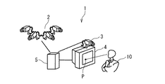
以下に、本発明の画像表示システムの実施の形態について図面を参照して説明する。図1は、本発明の画像表示システムの実施の形態の構成を示す概念図である。本実施の形態における画像表示システム1は、監視対象画像撮影装置2と、顔画像撮影装置3と、画像表示装置4と、コンピュータ5を備えている。監視対象画像撮影装置2とコンピュータ5とは互いに電気的に接続されている。コンピュータ5は、監視対象画像撮影装置2から出力されるデータを受信している。顔画像撮影装置3とコンピュータ5とは互いに電気的に接続されている。コンピュータ5は、顔画像撮影装置3から出力されるデータを受信している。画像表示装置4はコンピュータ5に電気的に接続されている。コンピュータ5から送信される表示画像データを受信して画像を表示している。監視対象画像撮影装置2、顔画像撮影装置3、画像表示装置4、及びコンピュータ5の接続は、所定のネットワークを介して行われていても良い。
Embodiments of an image display system according to the present invention will be described below with reference to the drawings. FIG. 1 is a conceptual diagram showing a configuration of an embodiment of an image display system of the present invention. The image display system 1 according to the present embodiment includes a monitoring target
観察者10は、画像表示装置4に表示されている画像を観察する。図1に示されている顔正面点Pは、観察者10が画像表示装置4に表示されている画像を見ているとき、その顔の正面に位置する画像表示装置4の画面上の部分を示している。本発明において、観察者10に対する制限は存在しない。つまり、本発明によれば、観察者10は、画像表示システム1の技術に関する詳しい知識を有することなく、画像表示システム1を利用することが可能である。
The
監視対象画像撮影装置2は、人の視界の範囲を超える範囲(以下、広範囲と呼ぶ。)の画像を撮影する。光学カメラやCCDカメラに例示される。監視対象画像撮影装置2は、複数の撮影装置によって構成されている。それにより、複数の地点から特定の地点を観察する多視点監視を実行することも可能になる。監視対象画像撮影装置2で撮影された観察対象の画像は、観察画像データに変換されコンピュータ5に送信される。本発明の監視対象画像撮影装置2は、この構成に限定されない。例えば、特定の地点から広範囲の観察を行う場合、パノラマカメラのような広範囲の撮影が可能な単一の撮影装置によって構成されていても良い。
The monitoring target
顔画像撮影装置3は、観察者10の顔画像を撮影する。光学カメラやCCDカメラに例示される。顔画像撮影装置3は、撮影した顔画像を顔画像データにしてコンピュータ5に送信する。顔画像撮影装置3は、観察者10の顔の位置に対して、相対的な位置が特定できる場所に設置されていることが望ましい。または、画像表示装置4の所定の位置を原点として、顔画像撮影装置3の座標を特定することで顔画像撮影装置3の設置位置を特定しても良い。
The face
コンピュータ5は、監視対象画像撮影装置2と顔画像撮影装置3とから送信される画像データ(観察画像データ/顔画像データ)に基づいてデータ処理を実行する。ワークステーションやパーソナルコンピュータに例示される。コンピュータ5は、受信した画像データ(観察画像データ/顔画像データ)に応答して所定のプログラムを実行して画像処理を行う。コンピュータ5は、画像処理により生成された表示画像データを画像表示装置4へ出力する。画像表示装置4は、コンピュータ5から送信される表示画像データを表示する。CRTや液晶ディスプレイに例示される。
The computer 5 executes data processing based on image data (observation image data / face image data) transmitted from the monitoring target
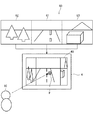
図2は、本発明の画像表示システム実施の形態の動作を示す概念図である。ここでは、監視対象画像撮影装置2は第1〜第3の3台の撮影装置を使用して観察対象を撮影しているものとする。例えば、各撮影装置が概ね水平挟角90度の視野角を有している場合、上述の3台の撮影装置によって水平角270度の観察が可能になる。
FIG. 2 is a conceptual diagram showing the operation of the embodiment of the image display system of the present invention. Here, it is assumed that the monitoring target
監視対象画像撮影装置2は、3台の撮影装置を使用して観察対象を撮影する。そして、複数の画像データを取得する。複数の画像データとしての第1画像データG1、第2画像データG2および第3画像データG3の各々は、その第1〜第3の撮影装置で撮影されたそれぞれの画像を示している。監視対象画像撮影装置2は、撮影された複数の画像データをコンピュータ5へ送信する。
The monitoring target
コンピュータ5は、送信された複数の画像データに基づいて、一つの基準画像データG0を生成する。また、顔画像撮影装置3は観察者10の顔画像を撮影してその顔画像データをコンピュータ5に送信する。コンピュータ5は、受信した顔画像データに応答して所定の演算を実行し、顔正面点Pを算出する。
The computer 5 generates one reference image data G0 based on the transmitted plurality of image data. Further, the face
コンピュータ5は、基準画像データG0と顔正面点Pとに基づいて、表示画像データを生成して画像表示装置4に送信する。図2の例では、コンピュータ5は、基準画像データG0と顔正面点Pとから、観察者10が第1画像データG1に注目していると判断する。コンピュータ5は、第1画像データG1を高解像度や表示領域を大きくして表示できるような表示画像データを生成する。このとき、第2画像データG2および第3画像データG3は低解像度や狭い表示領域となる。コンピュータ5は、生成された表示画像データを画像表示装置4に送信する。画像表示装置4は、受信した表示画像データに基づいて、第1画像データG1が拡大表示(高解像度表示)されている表示画像40を表示画面に表示する。観察者10は、表示された表示画像40によって、観察者10個人の視野の範囲を超える範囲に存在する観察対象の観察を実行することが可能になる。
The computer 5 generates display image data based on the reference image data G0 and the face front point P, and transmits the display image data to the
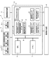
以下に、本発明の画像表示システムの実施の形態について、より詳細に説明する。図3は、本発明の画像表示システムの実施の形態の詳細な構成を示すブロック図である。図1の説明で述べたように、本実施の形態の画像表示システム1は、監視対象画像撮影装置2、顔画像撮影装置3、画像表示装置4、およびコンピュータ5を備えている。以下の説明では、前述の図1の構成と同様な部分に関しては詳細な説明を省略する。監視対象画像撮影装置2は、複数の撮影装置(2−1〜2−n)で構成されている。監視対象画像撮影装置2は、複数の撮影装置(2−1〜2−n)をそれぞれ任意の位置に設置することで、広範囲の監視や多視点からの監視を実行することが可能になる。
Hereinafter, embodiments of the image display system of the present invention will be described in more detail. FIG. 3 is a block diagram showing a detailed configuration of the embodiment of the image display system of the present invention. As described in the description of FIG. 1, the image display system 1 of the present embodiment includes the monitoring target
コンピュータ5は、CPU6とメモリ7と記憶装置8とを備えている。コンピュータ5は、ネットワーク(図示されず)に接続されていても良い。CPU6、メモリ7、及び記憶装置8は、バス9を介して互いに接続されている。CPU6は、コンピュータ5に少なくとも一つ備えられている演算処理装置である。CPU6は、コンピュータ5に内蔵または外付けされている装置の制御を行うための命令や、入力されたデータに対する演算処理を実行して、その演算処理結果を出力する。
The computer 5 includes a
メモリ7は、コンピュータ5に備えられている情報記憶装置である。メモリ7は、RAMのような半導体記憶装置に例示される。CPU6からの命令に応答して所定のデータを記憶する。記憶装置8は、コンピュータ5に備えられている大容量記憶装置である。記憶装置8は、HDDに例示され、不揮発性の記憶領域を有する。本実施の形態に用いられる電子データ(11〜14)やコンピュータプログラム(21〜24)を格納している。
The
記憶装置8に格納された電子データは、表示装置データ11、顔画像撮影装置データ12、顔姿勢初期データ13およびレイアウトデータ14を含む。表示装置データ11、顔画像撮影装置データ12、顔姿勢初期データ13およびレイアウトデータ14の各々は、画像表示システム1の動作を実行するために使用される。
The electronic data stored in the
表示装置データ11は、画像表示装置4に関する情報を示すデータである。そのデータは、画像を表示画面に表示するために必要な、画像表示装置4の表示画面サイズや表示可能解像度などの情報に例示される。
The display device data 11 is data indicating information related to the
顔画像撮影装置データ12は、顔画像撮影装置3の設置位置を示すデータである。そのデータは、顔画像撮影装置3で撮影された画像データから顔姿勢データ(観察者10の視線方向を特定するためのデータ)を算出するために必要な、顔画像撮影装置3の設置位置に関する情報に例示される。
The face image photographing
顔姿勢初期データ13は、顔姿勢データを算出するために使用される初期データである。そのデータは、観察者10が画像表示装置4の表示画面の左隅を注視している顔画像データを顔姿勢初期データ13に例示される。予め顔姿勢初期データ13を格納しておくことで、顔正面点Pの算出に要する情報処理量を低減することが可能になる。観察者10と画像表示装置4の特定点との相対的な距離を顔姿勢初期データ13として格納しても良い。
The face posture
レイアウトデータ14は、監視対象画像を画像表示装置4に表示する場合の表示レイアウトに関するデータである。監視対象の画像(広範囲画像または多視点画像)は、監視対象画像撮影装置2で撮影された画像をコンピュータ5で画像処理を実行することで生成される。コンピュータ5は、生成された監視対象画像を画像表示装置4に表示する場合、顔正面点Pに対応する領域を特定する。コンピュータ5は、その特定された領域を高解像で表示可能なように表示データを生成する。したがって、レイアウトデータ14に設定を変更することで、画像表示装置4での表示形態を任意に変更することが可能になる。
The
記憶装置8に格納されたコンピュータプログラムは、基準画像データ生成プログラム21、顔姿勢データ生成プログラム22、顔正面点検出プログラム23および表示画像データ生成プログラム24を含む。基準画像データ生成プログラム21、顔姿勢データ生成プログラム22、顔正面点検出プログラム23および表示画像データ生成プログラム24の各々は、画像表示システム1の動作を実行するために使用される。
The computer programs stored in the
基準画像データ生成プログラム21は、監視対象画像撮影装置2から送信された監視対象の画像データ(例示:図2のG1〜G3)に基づいて、表示画像データ生成のための基準となる基準画像データ(例示:図2のG0)を生成する。例えば、基準画像データ生成プログラム21は、複数の撮影装置(2−1〜2−n)で撮影された画像にオーバーラップが存在しているとき、オーバーラップのないシームレスな画像に対応する基準画像データを生成する。
The reference image
顔姿勢データ生成プログラム22は、顔画像撮影装置3から送信された顔画像データと顔姿勢初期データ13と表示装置データ11とに基づいて、観察者10に関する現在の顔姿勢データ(観察者10の視線方向を特定するためのデータ)を生成する。
The face posture
顔正面点検出プログラム23は、顔姿勢データ生成プログラム22で生成された顔姿勢データと表示装置データ11と顔画像撮影装置データ12とに基づいて、画像表示装置4の表示画面上の顔正面点Pを算出する。
The face front
表示画像データ生成プログラム24は、基準画像データ生成プログラム21で生成された基準画像データと顔正面点検出プログラム23で算出された顔正面点Pとレイアウトデータ14とに基づいて、表示画像データを生成する。
The display image
なお、本発明の作用効果を得るために、必ずしも上述の各データや各プログラムが全て要求されることは無い。例えば、より高性能なコンピュータ5を使用している場合などでは、顔姿勢データ生成プログラム22がレイアウトデータ14を使用せずに表示画像データを生成する構成であってもよい。その場合でも、本発明の作用効果に影響はない。
In order to obtain the operational effects of the present invention, the above-described data and programs are not necessarily required. For example, when using a higher-performance computer 5, the face posture
次に、本発明の画像表示システムの実施の形態の動作について説明する。図4は、本発明の画像表示システムの実施の形態の動作を示すフローチャートである。以下の動作において、必要とされるデータは記憶装置8に予め格納されているとして説明する。
Next, the operation of the embodiment of the image display system of the present invention will be described. FIG. 4 is a flowchart showing the operation of the embodiment of the image display system of the present invention. In the following operation, it is assumed that necessary data is stored in the
画像表示システム1が起動され、画像表示装置4が監視対象画像を表示する。表示されている画像は、監視対象画像撮影装置2によって所定の時間間隔で連続的に撮影され、コンピュータ5で所定の画像処理が実行された基準画像データである。基準画像データは、連続的に更新されている。観察者10は、その表示されている画像を肉眼で見る。
The image display system 1 is activated and the
ステップS101において、顔画像撮影装置3は、観察者10の顔画像を撮影する。この撮影が実行される時間間隔は、観察者10の顔正面点移動を十分に検出できる程度に短い間隔で行われる。顔画像撮影装置3は、撮影された顔画像を顔画像データとしてデータ処理可能な形式に形式変換して、ネットワークを介してコンピュータ5に送信する。
In step S <b> 101, the face
ステップS102において、コンピュータ5は、顔画像撮影装置3から送信される顔画像データに応答して、顔姿勢データ生成プログラム22を起動する。コンピュータ5のCPU6は、顔姿勢データ生成プログラム22の起動に応答して、顔姿勢初期データ13と表示装置データ11とを読み込む。そして、顔姿勢初期データ13と顔画像データと表示装置データ11とに基づいて、観察者10の現在の顔姿勢データを算出する。この処理を行う技術の一例として、「『3Dアピアランスモデルを用いた高速・高精度な顔姿勢推定』(2004年 電子情報通信学会総合大会論文集 D−12−99)」に記載の顔姿勢推定技術を利用可能である。この顔姿勢推定技術を顔姿勢データ生成プログラム22に含ませることにより、顔画像撮影装置3に対する観察者10の顔姿勢を算出できる。したがって、顔画像撮影装置3と画像表示装置4と間の位置関係を予め求めておくことにより、画像表示装置4に対する観察者10の顔姿勢データを演算で求めることができる。コンピュータ5は顔姿勢データの算出完了に応答してステップS103の処理に進む。
In step S <b> 102, the computer 5 activates the face posture
ステップS103において、コンピュータ5は顔正面点検出プログラム23を起動する。コンピュータ5のCPU6は、顔正面点検出プログラム23の起動に応答して、更に、顔画像撮影装置データ12を読み込む。そして、顔姿勢データと表示装置データ11と顔画像撮影装置データ12とに基づいて、顔正面点Pを特定する。コンピュータ5は顔正面点Pの特定完了に応答してステップS103の処理に進む。
In step S <b> 103, the computer 5 activates the face front
ステップS104において、コンピュータ5は、表示画像データ生成プログラム24を起動する。コンピュータ5のCPU6は、表示画像データ生成プログラム24の起動に応答して、監視対象画像撮影装置2が撮影しコンピュータ5で画像処理された基準画像データと顔正面点Pとレイアウトデータ14とに基づいて表示画像データを生成する。表示画像データは、顔正面点Pに対応する表示領域(高解像度表示領域)に高解像度画像が表示されるように生成されている。コンピュータ5は、表示画像データの生成完了に応答してステップS105の処理に進む。
In step S <b> 104, the computer 5 activates the display image
ステップS105において、ステップ104の実行の間に顔正面点Pが移動したかどうかの判断が実行される。例えば、ステップS103のようなプロセスを再実行し、前回特定した顔正面点と今回特定した顔正面点とが同じであれば、移動していないと判定する。その判断の結果、顔正面点の移動が検出されなかった場合(ステップS105:NO)、コンピュータ5は、ステップS104で生成された表示画像データを、ネットワークを介して画像表示装置4へ送信する。表示画像データ生成後に、顔正面点移動を検出した場合(ステップS105:YES)、処理はステップS106に進む。
In step S105, it is determined whether or not the face front point P has moved during the execution of step 104. For example, if the process as in step S103 is performed again and the face front point specified last time is the same as the face front point specified this time, it is determined that the face has not moved. As a result of the determination, if the movement of the face front point is not detected (step S105: NO), the computer 5 transmits the display image data generated in step S104 to the
ステップS106において、コンピュータ5は、検出された移動後の顔正面点P(ステップS105で算出したもの)に関するデータ(以下、顔正面点データという)の読み込みを実行する。顔正面点データとしては、画像表示装置4の画面内の座標に例示される。
In step S106, the computer 5 executes reading of data (hereinafter referred to as face front point data) relating to the detected face front point P after movement (calculated in step S105). The face front point data is exemplified by coordinates in the screen of the
ステップS107において、コンピュータ5は、顔正面点データの読み込み完了に応答して、表示画像データ(ステップS104で生成されたもの)の読み込みを実行する。顔正面点データと表示画像データの各々の読み込み完了に応答して、処理はステップS108に進む。 In step S107, the computer 5 reads the display image data (generated in step S104) in response to the completion of reading the face front point data. In response to the completion of reading each of the face front point data and the display image data, the process proceeds to step S108.
ステップS108において、コンピュータ5は顔正面点Pが、読込んだ表示画像データの高解像度表示領域に対応しているかどうかの判断を実行する。その判断の結果、現在の表示画像データに対応させた場合、高解像度で画像が表示される領域(高解像度表示領域)と顔正面点Pとが対応していなかった場合(ステップS108:YES)、処理はステップS101に戻り、新たな表示画像データの生成が行われる。ステップS108で顔正面点Pは移動していたけれども、高解像度で画像が表示される領域から外れていなかった場合(ステップS108:NO)、コンピュータ5は、ステップS104で生成された表示画像データをネットワークを介して画像表示装置4に送信し、処理はステップS109に進む。
In step S108, the computer 5 determines whether the face front point P corresponds to the high-resolution display area of the read display image data. As a result of the determination, when it is made to correspond to the current display image data, the area where the image is displayed at high resolution (high resolution display area) and the face front point P do not correspond (step S108: YES). The processing returns to step S101, and new display image data is generated. If the face front point P has moved in step S108 but has not deviated from the area where the image is displayed with high resolution (step S108: NO), the computer 5 displays the display image data generated in step S104. The image data is transmitted to the
ステップS109において、画像表示装置4は、コンピュータ5から送信された表示画像データを受信し、その表示画像データに対応する画像を表示画面に表示する。この動作を繰り返すことで、画像表示システム1は、観察者10の顔正面点移動に追従して観察者10が注目している箇所に対応する領域を自動的に高解像度で表示することができる。
In step S109, the
なお、上記動作において、ステップS105〜ステップS108を省略することも可能である。その場合、画像表示の実行、更新がより迅速になる。 In the above operation, steps S105 to S108 can be omitted. In that case, the execution and update of the image display become quicker.
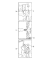
次に、本発明の画像表示システムの具体的な利用について説明する。図5は、画像表示システム1を車両の運行に適用した場合の構成を示す図である。車両30は、画像表示システム1を備えている移動体である。図5は、その車両30が交差点Pに侵入する様子を示している。図5を参照すると、車両30の左前近傍に二輪車B1が走行し、車両30の進行方向に対して右前方の道路に自動車C1が存在している。車両30には、監視対象画像撮影装置2(2−1〜2−3)と顔画像撮影装置3と画像表示装置4とコンピュータ5とが備えられている。また、観察者10(車両30の運転者)は、画像表示装置4の表示されている画像を見ながら車両の運行を行っている。第1画像撮影装置2−1は視野R1に対応する範囲の外部画像を撮影している。第2画像撮影装置2−2は視野R2に対応する範囲の外部画像を撮影している。第3画像撮影装置2−3は視野R3に対応する範囲の外部画像を撮影している。顔画像撮影装置3は、車両30内部に設置され、観察者10の顔画像を常時撮影している。
Next, specific use of the image display system of the present invention will be described. FIG. 5 is a diagram showing a configuration when the image display system 1 is applied to vehicle operation. The
第1画像撮影装置2−1〜第3画像撮影装置2−3は、撮影した外部画像を電子データ化する。そして、コンピュータ5で情報処理が可能な形式に形式変換して、車両30内部のネットワーク(図示されず)を介してコンピュータ5に送信する。同様に、顔画像撮影装置3は、撮影した顔画像を電子データ化する。そして、コンピュータ5で情報処理が可能な形式に形式変換して、ネットワークを介してコンピュータ5に送信する。コンピュータ5は受信した外部画像データと顔画像データとに基づいて画像処理を実行し、表示画像データを生成する。生成された表示画像データは、上述のネットワークを介して画像表示装置4に送信される。
The first image capturing device 2-1 to the third image capturing device 2-3 convert the captured external image into electronic data. Then, it is converted into a format that can be processed by the computer 5 and transmitted to the computer 5 via a network (not shown) inside the
図6は、第1画像撮影装置2−1〜第3画像撮影装置2−3で撮影された外部画像データを例示する図である。第1画像データG1は第1画像撮影装置2−1で撮影された画像データを示している。同様に第2画像G2データは第2画像撮影装置2−2で撮影された画像データを示し、第3画像データG3は、第3画像撮影装置2−3で撮影された画像データを示している。 FIG. 6 is a diagram illustrating external image data captured by the first image capturing device 2-1 to the third image capturing device 2-3. The first image data G1 indicates image data captured by the first image capturing device 2-1. Similarly, the second image G2 data indicates image data captured by the second image capturing device 2-2, and the third image data G3 indicates image data captured by the third image capturing device 2-3. .
図7は、上述の第1画像データG1〜第3画像データG3から表示画像データ40(40a、40b)を生成する動作を示した図である。基準外部画像データG0は、第1画像データG1〜第3画像データG3に基づいて生成された基準画像データである。図7に示されている基準画像データG0は、各画像データ(G1〜G3)を結合させて生成され、各々の画像データ(第1画像データG1〜第3画像データG3)の相対位置を特定している。なお、基準画像データG0の情報量を低減するために、各画像(G1〜G3)の横方向サイズを所定の比率で縮小した基準画像データG0を生成しても良い。生成された基準画像データG0は、顔正面点Pが検出されていない場合に画像表示装置4で表示される。システムが動作し、顔正面点Pの検出が実行されると、顔正面点データ50が生成される。顔正面点データ50は、本発明の理解を容易にするために、基準画像データG0に対応して顔正面点Pを示しているが、実際の顔正面点データは画面上の座標を示す数値データであっても良い。
FIG. 7 is a diagram showing an operation of generating display image data 40 (40a, 40b) from the first image data G1 to the third image data G3. The reference external image data G0 is reference image data generated based on the first image data G1 to the third image data G3. The reference image data G0 shown in FIG. 7 is generated by combining the image data (G1 to G3), and specifies the relative position of each image data (first image data G1 to third image data G3). is doing. In order to reduce the amount of information of the reference image data G0, reference image data G0 obtained by reducing the horizontal size of each image (G1 to G3) by a predetermined ratio may be generated. The generated reference image data G0 is displayed on the
ここで、観察者10の顔正面点Pが、図7に示されているように座標(50、50)で示される位置である場合、コンピュータ5はその座標で示される点に対応する領域を算出する。そしてコンピュータ5は、算出された領域と顔正面点データ50とに基づいて、上述の第1画像データG1に対応する画像G1aが高解像度で表示可能なように表示画像データを生成する。生成された表示画像データはネットワークを介して画像表示装置4に出力される。画像表示装置4は、コンピュータ5から供給された表示画像データに基づいて表示画像40aを画面に表示する。
Here, when the face front point P of the
観察者10が視線を移動させたことにより、顔正面点Pの位置が表示画像G1aの領域に存在しないと判断される場合を考える。コンピュータ5は、顔画像撮影装置3から送信される顔画像データに基づいて、観察者10の顔正面点移動を監視している。図7に示されているように、観察者10が視線を移動したことで顔正面点データ50の顔正面点Pの座標が、顔正面点P(5、25)を示した場合(以下、その顔正面点Pを“新たな顔正面点P”と呼ぶ。)、コンピュータ5は、その新たな顔正面点Pが表示画像G1aの領域に存在していないと判断する。
Consider a case where it is determined that the position of the face front point P does not exist in the region of the display image G1a due to the
コンピュータ5は、その判断結果に対応して、上記の新たな顔正面点Pの座標(顔正面点P(5、25))と画像表示装置4に出力している表示画像データとから、上述の第2画像データG2に対応する画像G2aが高解像度で表示可能なように、新たな表示画像データを生成する。生成された新たな表示画像データはネットワークを介して画像表示装置4に出力される。画像表示装置4は、コンピュータ5から供給された新たな表示画像データに基づいて新たな表示画像40bを画面に表示する。
Corresponding to the determination result, the computer 5 calculates the above-mentioned from the coordinates of the new face front point P (face front point P (5, 25)) and the display image data output to the
したがって、観察者10が顔を少し動かすだけで注目部分の画像が指定され、観察者10は、指定された領域の画像を高解像度で見ることができる。本発明を車両運行に用いることにより、観察者10(車両の運転者)の前方および左右の映像を死角を低減させることが可能になる。例えば、観察者10が、車両30を左折させる場合、左側に併走する二輪車B1の巻き込みを確認しなければならない。通常では観察者10は左の二輪車B1を目視するために顔を回転しなければならない。走行中に左の目視を実行することにより、前方不注意になる場合あり、また、左の目視を忘れて事故原因となることも多い。また、左側の二輪車B1に気をとられていると右側から来る自動車C1を見落とす可能性がある。
Therefore, the image of the attention portion is designated by moving the face of the observer 10 a little, and the
しかし、本発明によれば、正面向きの状態でも全体を目視可能な範囲に画像を表示する画像表示装置4に、左の二輪車B1から右の自動車C1までを含む広視野の画像が表示されている。したがって観察者10は、交差点周囲の状況を迅速に、かつ、容易に判断することができる。状況判断を正確行い、二輪車B1までの相対距離や二輪車B1大きさを確認するためには、第2画像データG2が高解像度で表示される必要がある。表示画像G1aを見ている観察者10が、表示画像G1aに表示されている二輪車B1存在に気がついた場合、顔を20〜30度(あるいはそれ以下の角度)動かすだけで、走行中に左の目視を実行した場合と同様の画像を見ることができる。また、右側の自動車C1も低解像度ながら常に表示されているため見落とす可能性が少なく、二輪車B1確認中もその存在に気づくことができる。
However, according to the present invention, an image with a wide field of view including the left motorcycle B1 to the right automobile C1 is displayed on the
なお、上記の説明では、本発明の画像表示システムを道路を走行する自動車に適用した場合について述べているが、これは、本発明の画像表示システムを適用する移動体を地上を走行する車両に限定するものではない。例えば、上記の画像表示システムと同様の構成を水上を航行する船舶などに備えることも可能である。 In the above description, the case where the image display system of the present invention is applied to an automobile traveling on a road is described. However, this applies to a vehicle that travels on the ground by applying a moving body to which the image display system of the present invention is applied. It is not limited. For example, it is possible to provide the same configuration as that of the above-described image display system in a ship navigating on the water.
本発明は、広域監視システム(複数の異なる場所に設置された監視カメラの画像を監視員が監視するシステム)に適用する場合においても、その効果を発揮する。図8は、本実施の形態を広域監視に適用した場合の構成を示す概念図である。図8に示されているように、この広域監視システムは、異なる地点を撮影する複数の撮影装置(2−1〜2−6)と、顔画像撮影装置3と、画像表示装置4と、コンピュータ5で構成されている。以下の説明において、前述した装置と同じ符号が付されている各装置は、前述のものと同様の構成を有しているものとし、その詳細な説明は省略する。
The present invention exerts its effect even when applied to a wide-area monitoring system (a system in which an observer monitors images of surveillance cameras installed at a plurality of different locations). FIG. 8 is a conceptual diagram showing a configuration when the present embodiment is applied to wide area monitoring. As shown in FIG. 8, the wide area monitoring system includes a plurality of photographing devices (2-1 to 2-6), a face
図8に示されているように、複数の撮影装置(2−1〜2−6)の各々は、一例として6箇所の異なる場所を撮影する6台の監視カメラで構成されている。各々の撮影装置は、ネットワーク(図示されず)を介してコンピュータ5に接続されている。複数の撮影装置(2−1〜2−6)は、それぞれの地点の様子を撮影した所定の画素の画像データを生成し、ネットワークを介してコンピュータ5出力する。また、顔画像撮影装置3および画像表示装置4も、そのネットワークを介してコンピュータ5に接続されている。観察者10は、画像表示装置4に表示されている画像を観察する人物である。
As shown in FIG. 8, each of the plurality of imaging devices (2-1 to 2-6) includes, as an example, six monitoring cameras that photograph six different places. Each photographing apparatus is connected to the computer 5 via a network (not shown). The plurality of photographing devices (2-1 to 2-6) generate image data of predetermined pixels that photograph the state of each point, and output the computer 5 via the network. The face
顔画像撮影装置3は、観察者10の顔を撮影する顔画像撮影装置である。顔画像撮影装置3は、上述のネットワークを介して、コンピュータ5と、画像表示装置4とに接続されている。顔画像撮影装置3によって撮影された観察者10の顔画像は、顔画像データに変換されてコンピュータ5に入力される。コンピュータ5は顔画像撮影装置3から供給された該顔画像データに基づいて観察者10の顔正面点Pを検出して顔正面点データを生成する。
The face
図9は、広域監視システムに本発明を適用した場合の動作を示す概念図である。各撮影地点に設置された撮影装置(2−1〜2−6)は、その撮影画像を電子データに変換してコンピュータ5に送信する。コンピュータ5は送信された画像データをネットワークを介して受信し、その受信に応答して基準画像データ生成プログラム21を起動する。コンピュータ5は、起動した基準画像データ生成プログラム21を実行することで基準画像データを生成する。その基準画像データは、第1画像撮影装置2−1〜2−6から送信される画像を低解像度化して並べ、画像表示装置4で表示可能な1枚の画像に統合することによって生成される。
FIG. 9 is a conceptual diagram showing an operation when the present invention is applied to a wide area monitoring system. The photographing devices (2-1 to 2-6) installed at each photographing point convert the photographed image into electronic data and transmit it to the computer 5. The computer 5 receives the transmitted image data via the network and activates the reference image
また、コンピュータ5は、顔画像撮影装置3から送信された顔画像データに基づいて顔姿勢データを生成する。生成される顔画像データは、顔姿勢データ生成プログラム22を実行することによって生成される。コンピュータ5は、顔姿勢データ生成プログラム22によって検出された顔姿勢データと、表示装置データ11の画面の位置情報を用いて、顔正面点P(顔の正面に位置する画面上の点)の位置を決定し、顔正面点Pとして出力する。さらに、顔正面点Pを含む領域に表示される監視カメラ画像の解像度を高くし、その他の監視カメラ画像の解像度を下げることによって表示画像データを生成する。
Further, the computer 5 generates face posture data based on the face image data transmitted from the face
上記の動作を具体的に説明する。広域監視システムを構成している第1画像撮影装置2−1〜第6画像撮影装置2−6は、異なる地点の画像データG1〜画像データG6を撮影する。撮影された各々の画像データ(G1〜G6)は、ネットワークを介してコンピュータ5に送信される。ここで、送信される各々の画像データの画素が360×240画素であるとし、画像表示装置4の表示可能画素サイズが360×240画素であるとする。
The above operation will be specifically described. The first image capturing device 2-1 to the sixth image capturing device 2-6 constituting the wide area monitoring system capture image data G1 to image data G6 at different points. Each photographed image data (G1 to G6) is transmitted to the computer 5 via the network. Here, it is assumed that the pixel of each image data to be transmitted is 360 × 240 pixels, and the displayable pixel size of the
コンピュータ5は、基準画像データ生成プログラム21を実行し、第1画像撮影装置2−1〜第6画像撮影装置2−6で撮影された画像を、図9の表示画像40cに示されているように、120×80画素の領域5つ(領域42〜領域46)と、約その2倍の解像度となる240×160画素の領域(領域41)ひとつに分割する。システムが動作を開始した時点(初期状態)では、コンピュータ5は、表示画像40cのように領域41を240×160画素、領域42〜領域46を120×80画素の領域に割り当てて画像表示装置4に表示させている。
The computer 5 executes the reference image
システムが動作している場合、コンピュータ5は、顔画像撮影装置3を用いて観察者10の顔画像を撮影し続ける。コンピュータ5は顔姿勢データ生成プログラム22を実行し、顔画像撮影装置3から送信される顔画像データに基づいて、観察者10の顔の3次元的な位置および向きを検出する。さらにコンピュータ5は、顔姿勢データ生成プログラム22を実行することによって算出される顔姿勢データと表示装置データ11と顔画像撮影装置データ12を用いて、顔正面点P(顔の位置から顔の向きに伸ばした直線と画像表示装置4の画面の交わる点)を顔正面点Pとして決定する。
When the system is operating, the computer 5 continues to photograph the face image of the
ここでコンピュータ5は、その顔正面点Pが領域41〜領域46のどの領域に含まれているかを判定し、顔正面点Pが含まれる領域を240×160画素の領域となるように新たな表示画像データを生成する。システム起動時点以外は、前回表示を行った時点での表示画像データに基づき、顔正面点Pがどの領域にあるかを判別する。例えば、顔正面点Pが領域46の領域内である場合、コンピュータ5は、表示画像40dに示されているように、領域46を左下の240×160画素の領域として表示画像データを生成する。その表示画像データにおいて、領域41〜領域45を120×80画素の領域とする。つまり、画像表示装置4で表示される監視対象画像は、画像データG1〜画像データG6をそれぞれ領域領域41〜領域46の解像度に変更して表示画像データが表示される。
Here, the computer 5 determines which of the
上述の例では、解像度の拡大量を2倍で一定であるとしたが、これはレイアウトデータ14の設定を変更することで任意に変更可能である。特に、顔の位置がディスプレイに近くなった場合に大きくし、遠くなった場合に小さくする、などの処理を行うことにより、視聴者が解像度の変化量を必要に応じて変えることも可能である。
In the example described above, the amount of enlargement of the resolution is assumed to be constant at twice, but this can be arbitrarily changed by changing the setting of the
このように広域監視システムに本発明を適用することによって、監視員は一度に複数地点を常時監視することができ、かつ、異常が発生した疑いがある地点を表示している画像を、視線に追従するように拡大表示させることができる。本発明により、観察者10は、スイッチ操作などを行わなくても顔をすこし動かすだけで、対象領域を高解像で表示させて確認することができるため、以上発生時に迅速に対応することができる。また、本発明により、観察者10は、特別な装置を装着することなく広域監視を実行することができる。
In this way, by applying the present invention to the wide area monitoring system, an observer can constantly monitor a plurality of points at a time, and an image displaying a point where there is a suspicion that an abnormality has occurred is displayed on the line of sight. It can be enlarged and displayed to follow. According to the present invention, since the
Claims (21)
前記画像表示装置で表示される表示画像の表示画像データを生成する画像生成装置と、
前記表示画像は複数の領域を有し、
前記表示画像を見るヒトの顔画像を撮影する顔画像撮影装置と、
前記顔画像から顔画像データを生成し、前記顔画像データに基づいて前記表示画像上における前記ヒトの顔の正面に位置する点としての顔正面点を検出する顔正面点検出装置と
を備え、
前記画像生成装置は、前記複数の領域から前記顔正面点に対応する特定領域を特定して、前記特定領域に対応する画像が提供する情報量を増加させて前記表示画像データを生成し、情報記憶部を有し、
前記情報記憶部は、前記画像表示装置の情報を示す表示装置データと、前記顔画像撮影装置の情報を示す顔画像撮影装置データを記憶し、
前記顔正面点検出装置は、前記顔画像に基づいて3次元画像処理を実行して前記顔画像データを生成し、前記顔画像データと前記表示装置データおよび前記顔画像撮影装置データに基づいて前記顔正面点を検出する
画像表示システム。An image display device;
An image generation device for generating display image data of a display image displayed on the image display device;
The display image has a plurality of regions,
A face image photographing device for photographing a human face image viewing the display image;
A face front point detection device that generates face image data from the face image and detects a face front point as a point located in front of the human face on the display image based on the face image data;
The image generation device specifies a specific region corresponding to the face front point from the plurality of regions, increases the amount of information provided by the image corresponding to the specific region, generates the display image data, Having a storage unit,
The information storage unit stores display device data indicating information of the image display device and face image capturing device data indicating information of the face image capturing device,
The face front point detection device performs three-dimensional image processing based on the face image to generate the face image data, and based on the face image data, the display device data, and the face image photographing device data An image display system that detects face front points.
前記顔正面点検出装置は、新たな顔正面点を検出し、
前記画像生成装置は、前記新たな顔正面点が前記特定領域から遷移した場合、新たな領域を特定し、前記新たな領域に対応する画像が提供する情報量を増加させて新たな表示画像データを生成する
画像表示システム。The image display system according to claim 1 ,
The face front point detection device detects a new face front point,
When the new face front point transitions from the specific area, the image generation apparatus specifies a new area, and increases the amount of information provided by the image corresponding to the new area to generate new display image data. Generate an image display system.
前記画像生成装置は、画像が提供する情報量の増加を、前記画像表示装置で表示されるときの画像の表示サイズを相対的に大きくすることで行う
画像表示システム。The image display system according to claim 1 or 2 ,
The image generation apparatus is configured to increase an amount of information provided by an image by relatively increasing a display size of the image when displayed on the image display device.
前記画像生成装置は、画像が提供する情報量の増加を、前記画像表示装置で表示されるときの画像の解像度を、相対的に高くすることで行う
画像表示システム。The image display system according to claim 1 or 2 ,
The image generation apparatus performs an increase in the amount of information provided by an image by relatively increasing the resolution of the image when displayed on the image display device.
前記画像生成装置は、前記ヒトの視界の範囲を超える範囲の画像を撮影する広範囲撮影装置で撮影された広範囲画像を前記表示画像に構成し、
前記画像表示装置は、前記広範囲画像で構成された前記表示画像データを、前記複数の領域に対応させ前記ヒトの視界の範囲内に入るように表示する
画像表示システム。The image display system according to any one of claims 1 to 4 ,
The image generation device configures a wide-range image captured by a wide-range imaging device that captures an image in a range that exceeds the range of the human field of view as the display image,
The image display device displays the display image data composed of the wide-range image so as to correspond to the plurality of regions and fall within the range of the human visual field.
前記画像生成装置は、前記広範囲撮影装置としての複数の撮影装置で撮影された複数の画像を、前記表示画像に合成し、
前記画像表示装置は、前記ヒトの視界の範囲内に入るように、前記複数の領域に対応して前記表示画像データを表示する
画像表示システム。The image display system according to claim 5 ,
The image generation device combines a plurality of images captured by a plurality of imaging devices as the wide-range imaging device with the display image,
The image display system displays the display image data corresponding to the plurality of regions so as to fall within a range of the human visual field.
(b)前記表示画像を見るヒトの顔画像を撮影するステップと、
(c)前記顔画像から顔姿勢を含む顔画像データを生成し、前記顔画像データに基づいて前記表示画像上における前記ヒトの顔の正面に位置する点を前記ヒトの顔正面点として検出するステップと、
(d)前記複数の領域から前記顔正面点に対応する特定領域を特定して、前記特定領域に対応する画像が提供する情報量を増加させて前記表示画像データを生成するステップと、
(e)前記表示画像データを前記画像表示装置で表示するステップと
を具備し、
前記(c)ステップは、
(c1)前記画像表示装置の情報を示す表示装置データと、前記顔画像を撮影する顔画像撮影装置の情報を示す顔画像撮影装置データを読み出すステップと、
(c2)前記顔画像に基づいて3次元画像処理を実行して前記顔画像データを生成し、
前記顔画像データと前記表示装置データおよび前記顔画像撮影装置データに基づいて前記顔正面点を検出するステップと
を備える
画像表示方法。(A) generating display image data of a display image displayed on the image display device, and the display image has a plurality of regions;
(B) photographing a human face image viewing the display image;
(C) generating face image data including a face posture from the face image, and detecting a point located in front of the human face on the display image as the human face front point based on the face image data Steps,
(D) specifying a specific area corresponding to the face front point from the plurality of areas, generating an amount of information provided by an image corresponding to the specific area, and generating the display image data;
(E) displaying the display image data on the image display device,
The step (c) includes:
(C1) reading display device data indicating information of the image display device, and face image capturing device data indicating information of the face image capturing device that captures the face image;
(C2) performing three-dimensional image processing based on the face image to generate the face image data;
An image display method comprising: detecting the face front point based on the face image data, the display device data, and the face image photographing device data.
(f)新たな顔正面点を検出するステップと、
(g)前記新たな顔正面点が前記特定領域から遷移した場合、新たな特定領域を特定し、前記新たな特定領域に対応する画像が提供する情報量を増加させて新たな表示画像データを生成するステップと
をさらに具備する
画像表示方法。The image display method according to claim 7 ,
(F) detecting a new face front point;
(G) When the new face front point transitions from the specific area, the new specific area is specified, and the amount of information provided by the image corresponding to the new specific area is increased to obtain new display image data. An image display method further comprising: generating.
画像が提供する情報量の増加は、前記画像表示装置で表示されるときの画像の表示サイズを相対的に大きくすることで行う
画像表示方法。The image display method according to claim 7 or 8 ,
An increase in the amount of information provided by an image is performed by relatively increasing the display size of the image when displayed on the image display device.
画像が提供する情報量の増加は、前記画像表示装置で表示されるときの画像の解像度を、相対的に高くすることで行う
画像表示方法。The image display method according to claim 7 or 8 ,
An increase in the amount of information provided by an image is performed by relatively increasing the resolution of the image when displayed on the image display device.
前記(a)ステップは、
(a1)前記ヒトの視界の範囲を超える範囲の画像を撮影する広範囲撮影装置で撮影された広範囲画像を前記表示画像に構成するステップを備え、
前記(e)ステップは、
(e1)前記広範囲画像で構成された前記表示画像データを、前記複数の領域に対応させ前記ヒトの視界の範囲内に入るように表示するステップを備える
画像表示方法。The image display method according to any one of claims 7 to 10 ,
The step (a) includes:
(A1) comprising, in the display image, a wide-range image captured by a wide-range imaging device that captures an image in a range that exceeds the range of the human visual field,
The step (e) includes:
(E1) An image display method comprising a step of displaying the display image data composed of the wide range image so as to correspond to the plurality of regions and fall within the range of the human field of view.
前記(a1)ステップは、
(a11)前記広範囲撮影装置としての複数の撮影装置で撮影された複数の画像を、前記表示画像に合成するステップを備え、
前記複数の領域の各々は、前記複数の画像の各々に対応し、
前記(e1)ステップは、
(e11)前記ヒトの視界の範囲内に入るように、前記複数の領域に対応して前記表示画像データを表示するステップを備える
画像表示方法。The image display method according to claim 11 ,
The step (a1) includes:
(A11) comprising a step of combining a plurality of images photographed by a plurality of photographing devices as the wide range photographing device with the display image;
Each of the plurality of regions corresponds to each of the plurality of images;
The step (e1) includes
(E11) An image display method comprising a step of displaying the display image data corresponding to the plurality of regions so as to fall within a range of the human visual field.
(i)前記表示画像を見るヒトの顔画像から顔画像データを生成し、前記顔画像データに基づいて前記表示画像上における前記ヒトの顔の正面に位置する点を前記ヒトの顔正面点として検出するステップと、
(j)前記複数の領域から前記顔正面点に対応する特定領域を特定して、前記特定領域に対応する画像が提供する情報量を増加させて前記表示画像データを生成するステップと、
(k)前記表示画像データを前記画像表示装置へ出力するステップと
を具備し、
前記(i)ステップは、
(i1)前記画像表示装置の情報を示す表示装置データと、前記顔画像を撮影する顔画像撮影装置の情報を示す顔画像撮影装置データを読み出すステップと、
(i2)前記顔画像に基づいて3次元画像処理を実行して前記顔画像データを生成し、
前記顔画像データと前記表示装置データおよび前記顔画像撮影装置データに基づいて前記顔正面点を検出するステップと
を備える方法をコンピュータで実行可能なプログラム。(H) generating display image data of a display image displayed on the image display device; and the display image has a plurality of regions;
(I) Face image data is generated from a human face image viewing the display image, and a point located in front of the human face on the display image based on the face image data is defined as the human face front point. Detecting step;
(J) specifying a specific area corresponding to the face front point from the plurality of areas, and generating the display image data by increasing an amount of information provided by an image corresponding to the specific area;
(K) outputting the display image data to the image display device,
The step (i)
(I1) reading display device data indicating information of the image display device, and face image capturing device data indicating information of the face image capturing device that captures the face image;
(I2) generating 3D image processing based on the face image to generate the face image data;
A computer-executable program comprising: a step of detecting the face front point based on the face image data, the display device data, and the face image photographing device data.
(l)新たな顔正面点を検出するステップと、
(m)前記新たな顔正面点が前記特定領域から遷移した場合、新たな特定領域を特定し、前記新たな特定領域に対応する画像が提供する情報量を増加させて新たな表示画像データを生成するステップと
をさらに具備するプログラム。The program according to claim 13 , wherein
(L) detecting a new face front point;
(M) When the new face front point transitions from the specific area, the new specific area is specified, and the amount of information provided by the image corresponding to the new specific area is increased to obtain new display image data. A program further comprising the step of generating.
画像が提供する情報量の増加は、前記画像表示装置で表示されるときの画像の表示サイズを相対的に大きくすることで行う
プログラム。The program according to claim 13 or 14 ,
A program for increasing the amount of information provided by an image by relatively increasing the display size of the image when displayed on the image display device.
画像が提供する情報量の増加は、前記画像表示装置で表示されるときの画像の解像度を、相対的に高くすることで行う
プログラム。The program according to claim 13 or 14 ,
A program for increasing the amount of information provided by an image by relatively increasing the resolution of the image when displayed on the image display device.
前記(h)ステップは、
(h1)前記ヒトの視界の範囲を超える範囲の画像を撮影する広範囲撮影装置で撮影された広範囲画像を前記表示画像に構成するステップを備え、
前記(k)ステップは、
(k1)前記広範囲画像で構成された前記表示画像データが、前記複数の領域に対応させ前記ヒトの視界の範囲内に入るように表示されるように、前記表示画像データを前記画像表示装置へ出力するステップを備える
プログラム。The program according to any one of claims 13 to 16 ,
The step (h) includes:
(H1) comprising, in the display image, a wide-range image captured by a wide-range imaging device that captures an image in a range that exceeds the range of the human visual field;
The step (k) includes
(K1) The display image data is displayed on the image display device so that the display image data composed of the wide range image is displayed so as to correspond to the plurality of regions and fall within the range of the human field of view. A program with steps to output.
前記(h1)ステップは、
(h11)前記広範囲撮影装置としての複数の撮影装置で撮影された複数の画像を、前記表示画像に合成するステップを備え、
前記複数の領域の各々は、前記複数の画像の各々に対応し、
前記(k1)ステップは、
(k11)前記ヒトの視界の範囲内に入り、前記複数の領域に対応して前記表示画像データを表示されるように、前記表示画像データを前記画像表示装置へ出力するステップを備える
プログラム。 The program according to claim 17 , wherein
The step (h1) includes
(H11) comprising a step of combining a plurality of images photographed by a plurality of photographing devices as the wide-range photographing device with the display image;
Each of the plurality of regions corresponds to each of the plurality of images;
The step (k1) includes
(K11) A program comprising a step of outputting the display image data to the image display device so that the display image data is displayed in correspondence with the plurality of regions within the range of the human visual field .
前記画像表示装置で表示される表示画像の表示画像データを生成する画像生成装置と、
前記表示画像は複数の領域を有し、
前記表示画像を見るヒトの顔画像を撮影する顔画像撮影装置と、
前記顔画像から顔姿勢を計算し、前記顔姿勢に基づいて前記表示画像上における前記ヒトの顔の正面に位置する点としての顔正面点を検出する顔正面点検出装置と
を備え、
前記画像生成装置は、前記複数の領域から前記顔正面点に対応する特定領域を特定して、前記特定領域に対応する画像が提供する情報量を増加させて前記表示画像データを生成し、情報記憶部を有し、
前記情報記憶部は、前記画像表示装置の情報を示す表示装置データと、前記顔画像撮影装置の情報を示す顔画像撮影装置データを記憶し、
前記顔正面点検出装置は、前記顔画像に基づいて3次元画像処理を実行して前記顔姿勢を計算し、前記顔姿勢と前記表示装置データおよび前記顔画像撮影装置データに基づいて前記顔正面点を検出する
画像表示システム。An image display device;
An image generation device for generating display image data of a display image displayed on the image display device;
The display image has a plurality of regions,
A face image photographing device for photographing a human face image viewing the display image;
A face front point detection device that calculates a face posture from the face image and detects a face front point as a point located in front of the human face on the display image based on the face posture;
The image generation device specifies a specific region corresponding to the face front point from the plurality of regions, increases the amount of information provided by the image corresponding to the specific region, generates the display image data, Having a storage unit,
The information storage unit stores display device data indicating information of the image display device and face image capturing device data indicating information of the face image capturing device,
The face front point detection device performs three-dimensional image processing based on the face image to calculate the face posture, and the face front point based on the face posture, the display device data, and the face image photographing device data. An image display system that detects points.
(b)前記表示画像を見るヒトの顔画像を撮影するステップと、
(c)前記顔画像から顔姿勢を計算し、前記顔姿勢に基づいて前記表示画像上における前記ヒトの顔の正面に位置する点を前記ヒトの顔正面点として検出するステップと、
(d)前記複数の領域から前記顔正面点に対応する特定領域を特定して、前記特定領域に対応する画像が提供する情報量を増加させて前記表示画像データを生成するステップと、
(e)前記表示画像データを前記画像表示装置で表示するステップと
を具備し、
前記(c)ステップは、
(c1)前記画像表示装置の情報を示す表示装置データと、前記顔画像を撮影する顔画像撮影装置の情報を示す顔画像撮影装置データを読み出すステップと、
(c2)前記顔画像に基づいて3次元画像処理を実行して前記顔姿勢を計算し、前記顔姿勢と前記表示装置データおよび前記顔画像撮影装置データに基づいて前記顔正面点を検出するステップと
を備える
画像表示方法。(A) generating display image data of a display image displayed on the image display device, and the display image has a plurality of regions;
(B) photographing a human face image viewing the display image;
(C) calculating a face posture from the face image and detecting a point located in front of the human face on the display image based on the face posture as the human face front point;
(D) specifying a specific area corresponding to the face front point from the plurality of areas, generating an amount of information provided by an image corresponding to the specific area, and generating the display image data;
(E) displaying the display image data on the image display device,
The step (c) includes:
(C1) reading display device data indicating information of the image display device, and face image capturing device data indicating information of the face image capturing device that captures the face image;
(C2) performing three-dimensional image processing based on the face image to calculate the face posture, and detecting the face front point based on the face posture, the display device data, and the face image photographing device data An image display method comprising:
(i)前記表示画像を見るヒトの顔画像から顔姿勢を計算し、前記顔姿勢に基づいて前記表示画像上における前記ヒトの顔の正面に位置する点を前記ヒトの顔正面点として検出するステップと、
(j)前記複数の領域から前記顔正面点に対応する特定領域を特定して、前記特定領域に対応する画像が提供する情報量を増加させて前記表示画像データを生成するステップと、
(k)前記表示画像データを前記画像表示装置へ出力するステップと
を具備し、
前記(i)ステップは、
(i1)前記画像表示装置の情報を示す表示装置データと、前記顔画像を撮影する顔画像撮影装置の情報を示す顔画像撮影装置データを読み出すステップと、
(i2)前記顔画像に基づいて3次元画像処理を実行して前記顔姿勢を計算し、前記顔姿勢と前記表示装置データおよび前記顔画像撮影装置データに基づいて前記顔正面点を検出するステップと
を備える方法をコンピュータで実行可能なプログラム。(H) generating display image data of a display image displayed on the image display device; and the display image has a plurality of regions;
(I) A face posture is calculated from a human face image viewing the display image, and a point located in front of the human face on the display image is detected as the human face front point based on the face posture. Steps,
(J) specifying a specific area corresponding to the face front point from the plurality of areas, and generating the display image data by increasing an amount of information provided by an image corresponding to the specific area;
(K) outputting the display image data to the image display device,
The step (i)
(I1) reading display device data indicating information of the image display device, and face image capturing device data indicating information of the face image capturing device that captures the face image;
(I2) performing three-dimensional image processing based on the face image to calculate the face posture, and detecting the face front point based on the face posture, the display device data, and the face image photographing device data A program that can execute a method comprising:
Priority Applications (1)
| Application Number | Priority Date | Filing Date | Title |
|---|---|---|---|
| JP2006514702A JP4952995B2 (en) | 2004-06-18 | 2005-06-08 | Image display system, image display method, and image display program |
Applications Claiming Priority (4)
| Application Number | Priority Date | Filing Date | Title |
|---|---|---|---|
| JP2004180485 | 2004-06-18 | ||
| JP2004180485 | 2004-06-18 | ||
| PCT/JP2005/010463 WO2005124735A1 (en) | 2004-06-18 | 2005-06-08 | Image display system, image display method, and image display program |
| JP2006514702A JP4952995B2 (en) | 2004-06-18 | 2005-06-08 | Image display system, image display method, and image display program |
Publications (2)
| Publication Number | Publication Date |
|---|---|
| JPWO2005124735A1 JPWO2005124735A1 (en) | 2008-07-31 |
| JP4952995B2 true JP4952995B2 (en) | 2012-06-13 |
Family
ID=35509944
Family Applications (1)
| Application Number | Title | Priority Date | Filing Date |
|---|---|---|---|
| JP2006514702A Active JP4952995B2 (en) | 2004-06-18 | 2005-06-08 | Image display system, image display method, and image display program |
Country Status (6)
| Country | Link |
|---|---|
| US (1) | US7839423B2 (en) |
| EP (1) | EP1768097A1 (en) |
| JP (1) | JP4952995B2 (en) |
| KR (1) | KR100911066B1 (en) |
| CN (1) | CN1969313A (en) |
| WO (1) | WO2005124735A1 (en) |
Families Citing this family (18)
| Publication number | Priority date | Publication date | Assignee | Title |
|---|---|---|---|---|
| JP4668803B2 (en) * | 2006-02-13 | 2011-04-13 | アルパイン株式会社 | Driving support image display control device |
| US9513699B2 (en) | 2007-10-24 | 2016-12-06 | Invention Science Fund I, LL | Method of selecting a second content based on a user's reaction to a first content |
| US9582805B2 (en) | 2007-10-24 | 2017-02-28 | Invention Science Fund I, Llc | Returning a personalized advertisement |
| US20090113297A1 (en) * | 2007-10-24 | 2009-04-30 | Searete Llc, A Limited Liability Corporation Of The State Of Delaware | Requesting a second content based on a user's reaction to a first content |
| JP4743234B2 (en) | 2008-07-02 | 2011-08-10 | ソニー株式会社 | Display device and display method |
| DE102009020328A1 (en) * | 2009-05-07 | 2010-11-11 | Bayerische Motoren Werke Aktiengesellschaft | A method for displaying differently well visible objects from the environment of a vehicle on the display of a display device |
| FR2956364B1 (en) * | 2010-02-18 | 2016-01-29 | Peugeot Citroen Automobiles Sa | DEVICE FOR AIDING THE MANEUVER OF A VEHICLE BY DISPLAYING POINTS OF VIEW FUNCTION OF THE POSITION OF THE HEAD OF THE DRIVER |
| US8463075B2 (en) * | 2010-08-11 | 2013-06-11 | International Business Machines Corporation | Dynamically resizing text area on a display device |
| JP6080346B2 (en) * | 2011-10-03 | 2017-02-15 | 株式会社日立国際電気 | Video display device |
| US10884577B2 (en) * | 2013-01-15 | 2021-01-05 | Poow Innovation Ltd. | Identification of dynamic icons based on eye movement |
| CN104919518B (en) * | 2013-01-24 | 2017-12-08 | 索尼公司 | Image display, method for displaying image and image display system |
| US11747895B2 (en) * | 2013-03-15 | 2023-09-05 | Intuitive Surgical Operations, Inc. | Robotic system providing user selectable actions associated with gaze tracking |
| CN104228684B (en) * | 2014-09-30 | 2017-02-15 | 吉林大学 | Method for eliminating dead zones of automobile A columns |
| CN106922140B (en) * | 2014-11-12 | 2019-12-03 | 三菱电机株式会社 | Display control unit and information display device |
| JP2016149651A (en) * | 2015-02-12 | 2016-08-18 | 株式会社デンソー | Display controller and display system |
| TWI547177B (en) * | 2015-08-11 | 2016-08-21 | 晶睿通訊股份有限公司 | Viewing Angle Switching Method and Camera Therefor |
| JP6449501B1 (en) * | 2018-03-28 | 2019-01-09 | Eizo株式会社 | Display system and program |
| CN113055587A (en) * | 2019-12-27 | 2021-06-29 | 财团法人工业技术研究院 | Panoramic video processing method, panoramic video processing device and panoramic video system |
Family Cites Families (23)
| Publication number | Priority date | Publication date | Assignee | Title |
|---|---|---|---|---|
| US4790028A (en) * | 1986-09-12 | 1988-12-06 | Westinghouse Electric Corp. | Method and apparatus for generating variably scaled displays |
| JPH01252993A (en) * | 1988-04-01 | 1989-10-09 | Nippon Telegr & Teleph Corp <Ntt> | Image display method |
| JP3159385B2 (en) * | 1989-11-30 | 2001-04-23 | 株式会社東芝 | Image display method and image display device |
| JP3031013B2 (en) | 1991-11-15 | 2000-04-10 | 日産自動車株式会社 | Visual information providing device |
| JPH08116556A (en) | 1994-10-14 | 1996-05-07 | Canon Inc | Image processing method and device |
| US5850352A (en) * | 1995-03-31 | 1998-12-15 | The Regents Of The University Of California | Immersive video, including video hypermosaicing to generate from multiple video views of a scene a three-dimensional video mosaic from which diverse virtual video scene images are synthesized, including panoramic, scene interactive and stereoscopic images |
| JP3272906B2 (en) * | 1995-05-29 | 2002-04-08 | シャープ株式会社 | Gaze direction detecting method and apparatus and man-machine interface apparatus including the same |
| JPH0981309A (en) * | 1995-09-13 | 1997-03-28 | Toshiba Corp | Input device |
| JPH09251342A (en) * | 1996-03-15 | 1997-09-22 | Toshiba Corp | Device and method for estimating closely watched part and device, information display device/method using the same |
| US5912721A (en) * | 1996-03-13 | 1999-06-15 | Kabushiki Kaisha Toshiba | Gaze detection apparatus and its method as well as information display apparatus |
| JPH09305156A (en) | 1996-05-16 | 1997-11-28 | Nippon Telegr & Teleph Corp <Ntt> | Video display method and device |
| JP3139959B2 (en) * | 1996-05-17 | 2001-03-05 | 鹿島建設株式会社 | Work machine operation support image system |
| US5731805A (en) * | 1996-06-25 | 1998-03-24 | Sun Microsystems, Inc. | Method and apparatus for eyetrack-driven text enlargement |
| JP2000059665A (en) | 1998-08-06 | 2000-02-25 | Mitsubishi Electric Corp | Image pickup device |
| US6292713B1 (en) * | 1999-05-20 | 2001-09-18 | Compaq Computer Corporation | Robotic telepresence system |
| JP2000347692A (en) | 1999-06-07 | 2000-12-15 | Sanyo Electric Co Ltd | Person detecting method, person detecting device, and control system using it |
| JP3298851B2 (en) * | 1999-08-18 | 2002-07-08 | 松下電器産業株式会社 | Multi-function vehicle camera system and image display method of multi-function vehicle camera |
| JP2003116125A (en) * | 2001-10-03 | 2003-04-18 | Auto Network Gijutsu Kenkyusho:Kk | Apparatus for visually confirming surrounding of vehicle |
| JP3909251B2 (en) | 2002-02-13 | 2007-04-25 | アルパイン株式会社 | Screen control device using line of sight |
| US6943799B2 (en) * | 2002-03-29 | 2005-09-13 | The Boeing Company | Gaze directed visual system |
| US20050047629A1 (en) * | 2003-08-25 | 2005-03-03 | International Business Machines Corporation | System and method for selectively expanding or contracting a portion of a display using eye-gaze tracking |
| JP4222183B2 (en) | 2003-10-29 | 2009-02-12 | 株式会社デンソー | Vehicle peripheral image display device |
| US7561143B1 (en) * | 2004-03-19 | 2009-07-14 | The University of the Arts | Using gaze actions to interact with a display |
-
2005
- 2005-06-08 KR KR1020087004520A patent/KR100911066B1/en active IP Right Grant
- 2005-06-08 CN CNA2005800200774A patent/CN1969313A/en active Pending
- 2005-06-08 WO PCT/JP2005/010463 patent/WO2005124735A1/en active Application Filing
- 2005-06-08 EP EP05748915A patent/EP1768097A1/en not_active Withdrawn
- 2005-06-08 US US11/570,863 patent/US7839423B2/en active Active
- 2005-06-08 JP JP2006514702A patent/JP4952995B2/en active Active
Also Published As
| Publication number | Publication date |
|---|---|
| US20080036790A1 (en) | 2008-02-14 |
| JPWO2005124735A1 (en) | 2008-07-31 |
| EP1768097A1 (en) | 2007-03-28 |
| US7839423B2 (en) | 2010-11-23 |
| KR100911066B1 (en) | 2009-08-06 |
| WO2005124735A1 (en) | 2005-12-29 |
| CN1969313A (en) | 2007-05-23 |
| KR20080024545A (en) | 2008-03-18 |
Similar Documents
| Publication | Publication Date | Title |
|---|---|---|
| JP4952995B2 (en) | Image display system, image display method, and image display program | |
| JP6899875B2 (en) | Information processing device, video display system, information processing device control method, and program | |
| JP6479199B2 (en) | Information processing device | |
| WO2016163183A1 (en) | Head-mounted display system and computer program for presenting real space surrounding environment of user in immersive virtual space | |
| JP7372061B2 (en) | Remote work support system | |
| US11240446B2 (en) | Imaging device, control apparatus, imaging method, and storage medium | |
| JP2017204674A (en) | Imaging device, head-mounted display, information processing system, and information processing method | |
| KR20140094116A (en) | parking assist method for vehicle through drag and drop | |
| US10359840B2 (en) | Method for operating a virtual reality system, and virtual reality system | |
| JP6649010B2 (en) | Information processing device | |
| JP6641122B2 (en) | Display device, information processing device, and control method therefor | |
| JP2015007722A (en) | Image display device | |
| KR100856966B1 (en) | Image display system, image display method and recording medium | |
| JP7247371B2 (en) | Image processing device, system, image processing method, and image processing program | |
| US11610343B2 (en) | Video display control apparatus, method, and non-transitory computer readable medium | |
| JP2009044597A (en) | Wide-angle image acquisition device | |
| JP7135378B2 (en) | Perimeter monitoring device | |
| JPH10291188A (en) | Stereogrpahic image presenting method | |
| WO2017094285A1 (en) | Distance measurement device | |
| JP2006005451A (en) | On-vehicle monitor | |
| JP2005252831A (en) | Support system for facility monitoring | |
| JP2012065010A (en) | Remote video monitoring system | |
| JP4730555B2 (en) | Radiation tomography system | |
| Kaynar et al. | AR IN VR: OMNISTEREOSCOPIC TELEPRESENCE WITH HOLOGRAMS FOR REMOTE MAINTENANCE AND COLLABORATION. | |
| JP2022053421A (en) | Display system, display method, and program for remote control |
Legal Events
| Date | Code | Title | Description |
|---|---|---|---|
| A621 | Written request for application examination |
Free format text: JAPANESE INTERMEDIATE CODE: A621 Effective date: 20080514 |
|
| A521 | Written amendment |
Free format text: JAPANESE INTERMEDIATE CODE: A523 Effective date: 20090129 |
|
| A131 | Notification of reasons for refusal |
Free format text: JAPANESE INTERMEDIATE CODE: A131 Effective date: 20110330 |
|
| A521 | Written amendment |
Free format text: JAPANESE INTERMEDIATE CODE: A523 Effective date: 20110527 |
|
| A131 | Notification of reasons for refusal |
Free format text: JAPANESE INTERMEDIATE CODE: A131 Effective date: 20111004 |
|
| A521 | Written amendment |
Free format text: JAPANESE INTERMEDIATE CODE: A523 Effective date: 20111205 |
|
| TRDD | Decision of grant or rejection written | ||
| A01 | Written decision to grant a patent or to grant a registration (utility model) |
Free format text: JAPANESE INTERMEDIATE CODE: A01 Effective date: 20120216 |
|
| A01 | Written decision to grant a patent or to grant a registration (utility model) |
Free format text: JAPANESE INTERMEDIATE CODE: A01 |
|
| A61 | First payment of annual fees (during grant procedure) |
Free format text: JAPANESE INTERMEDIATE CODE: A61 Effective date: 20120229 |
|
| R150 | Certificate of patent or registration of utility model |
Ref document number: 4952995 Country of ref document: JP Free format text: JAPANESE INTERMEDIATE CODE: R150 Free format text: JAPANESE INTERMEDIATE CODE: R150 |
|
| FPAY | Renewal fee payment (event date is renewal date of database) |
Free format text: PAYMENT UNTIL: 20150323 Year of fee payment: 3 |