JP4951258B2 - Steering column device - Google Patents
Steering column device Download PDFInfo
- Publication number
- JP4951258B2 JP4951258B2 JP2006089707A JP2006089707A JP4951258B2 JP 4951258 B2 JP4951258 B2 JP 4951258B2 JP 2006089707 A JP2006089707 A JP 2006089707A JP 2006089707 A JP2006089707 A JP 2006089707A JP 4951258 B2 JP4951258 B2 JP 4951258B2
- Authority
- JP
- Japan
- Prior art keywords
- pair
- jacket
- side brackets
- outer cylinder
- shaft
- Prior art date
- Legal status (The legal status is an assumption and is not a legal conclusion. Google has not performed a legal analysis and makes no representation as to the accuracy of the status listed.)
- Expired - Fee Related
Links
Images


Description
本発明は、ステアリングコラム装置に関し、ロアジャケットとアッパジャケットとの間の摺動部分に介在させる樹脂スリーブを剛性向上のための樹脂スペーサとして兼用することにより、部品点数を削減したものである。 The present invention relates to a steering column device, in which a resin sleeve interposed in a sliding portion between a lower jacket and an upper jacket is also used as a resin spacer for improving rigidity, thereby reducing the number of parts.
自動車の操舵機構には、ステアリングホィールを取り付けるためのステアリングコラム装置が設けられている。ステアリングコラム装置としては、特許文献1に開示されたものが知られている。即ち、車体に結合した支持ブラケットには下方へ突出する一対の支持板部が形成される一方、ステアリングシャフトを回転自在に支持するジャケットの下面には略U字形のブラケットの上部が溶接結合され、該ブラケットに形成された軸方向に長い長孔と、前記一対の支持板部に形成された上下方向に長い長孔とにチルトボルトが挿通され、該チルトボルトには前記一対の支持板部間の間隔を変更するチルトレバーが設けられている。該チルトレバーを緩めてブラケットと共にジャケットを昇降または前後移動させ、再び締め付けることにより、チルトまたはテレスコの調整が可能である。
A steering column device for attaching a steering wheel is provided in a steering mechanism of an automobile. As a steering column device, the one disclosed in
そして、ジャケットを上から被うようにして設けた逆U字形の樹脂スペーサの両端を、該ジャケットと一対の支持板部の夫々との間に介在させているので、一対の支持板部の下端部どうしの間をブラケットを介して連結するだけでなく、一対の支持板部の中間部どうしの間が隙間なく密着する構成となっており、車体左右方向でのステアリングシャフトの支持剛性が向上する。
ところが、一対の支持板部の中間部どうしの間を隙間なく密着させるために別個に樹脂スペーサを設けることから、部品点数が増加し、かつ組み付け工数が増え、製造コストが高くなる。 However, since resin spacers are separately provided to closely contact the intermediate portions of the pair of support plate portions without any gap, the number of parts increases, the number of assembly steps increases, and the manufacturing cost increases.
そこで本発明は、上記の課題を解決し、既存の部品を利用して樹脂スペーサを設けたのと同様の効果を生じさせたステアリングコラム装置を提供することを目的とする。 SUMMARY OF THE INVENTION Accordingly, an object of the present invention is to provide a steering column device that solves the above-described problems and produces an effect similar to that provided with a resin spacer using existing components.
請求項1に係る発明は、車体に結合され下方へ向かって突出する一対のサイドブラケットと、該一対のサイドブラケットの間に配置されておりロアシャフトと該ロアシャフトに対して軸方向へ相対的に移動自在なアッパシャフトとにより構成されるステアリングシャフトと、車体に結合され前記ロアシャフトを回転自在に支持するロアジャケットと、前記アッパシャフトを回転自在に支持するアッパジャケットと、該アッパジャケットの下部と前記ロアジャケットの上部とが摺動自在に重合して外筒と内筒とを構成する重合部と、前記外筒と前記内筒との間に介在させた樹脂スリーブと、前記アッパジャケットの下部に結合され長孔を有するディスタンスブラケットと、前記一対のサイドブラケットを貫通しかつ前記長孔に挿通されたチルトボルトを介して前記一対のサイドブラケット間を締め付けて前記アッパジャケットをテレスコ可能に前記一対のサイドブラケットに結合する締付手段とを備えたステアリングコラム装置において、
前記外筒には内外を貫通する一対の貫通孔を形成する一方、
前記樹脂スリーブの外周面には一対の突出部を形成し、
夫々の突出部を夫々の前記貫通孔に挿通させて前記外筒の外周面から突出させ、
前記外筒の外部へ突出する一対の突出部を前記一対のサイドブラケットの内側面に当接させたことを特徴とする。
The invention according to
While forming a pair of through-holes that penetrate the inside and outside of the outer cylinder,
A pair of protrusions are formed on the outer peripheral surface of the resin sleeve,
Each projecting portion is inserted through each of the through holes to project from the outer peripheral surface of the outer cylinder,
A pair of projecting portions projecting to the outside of the outer cylinder are brought into contact with inner side surfaces of the pair of side brackets.
この発明によれば、ロアジャケットとアッパジャケットとの重合部を構成する外筒の内部に樹脂スリーブを装着したので、テレスコ操作が行われる際にロアジャケットに対するアッパジャケットの摺動が円滑になる。また、外筒の外部へ突出する一対の突出部の夫々を一対のサイドブラケットの内側面に当接させたので、一対の突出部が外筒と一対のサイドブラケットとの間を埋める樹脂スペーサとして作用し、ステアリングシャフトの車体左右方向の支持剛性が向上する。更に、ロック時には樹脂スリーブが内筒を締め付けるように作用するため、内筒と外筒の重合部におけるガタの発生を防止できると共に、内筒の車体左右方向の支持剛性が向上する。 According to the present invention, since the resin sleeve is mounted inside the outer cylinder constituting the overlapping portion of the lower jacket and the upper jacket, the sliding of the upper jacket with respect to the lower jacket becomes smooth when a telescopic operation is performed. Further, since each of the pair of projecting portions projecting to the outside of the outer cylinder is brought into contact with the inner surfaces of the pair of side brackets, the pair of projecting sections serve as resin spacers that fill the space between the outer cylinder and the pair of side brackets. Acting, the support rigidity of the steering shaft in the left-right direction of the vehicle body is improved. Further, since the resin sleeve acts to tighten the inner cylinder when locked, it is possible to prevent the play from occurring in the overlapping portion of the inner cylinder and the outer cylinder and to improve the support rigidity of the inner cylinder in the lateral direction of the vehicle body.
請求項2に係る発明は、車体に結合され下方へ向かって突出する一対のサイドブラケットと、該一対のサイドブラケットの間に配置されておりロアシャフトと該ロアシャフトに対して軸方向へ相対的に移動自在なアッパシャフトとにより構成されるステアリングシャフトと、車体に結合され前記ロアシャフトを回転自在に支持するロアジャケットと、前記アッパシャフトを回転自在に支持するアッパジャケットと、該アッパジャケットの下部と前記ロアジャケットの上部とが摺動自在に重合して外筒と内筒とを構成する重合部と、前記外筒と前記内筒との間に介在させた樹脂スリーブと、前記アッパジャケットの下部に結合され長孔を有するディスタンスブラケットと、前記一対のサイドブラケットを貫通しかつ前記長孔に挿通されたチルトボルトを介して前記一対のサイドブラケット間を締め付けて前記アッパジャケットをテレスコ可能に前記一対のサイドブラケットに結合する締付手段とを備えたステアリングコラム装置において、
前記外筒には内外を貫通する一対の貫通孔を形成する一方、
前記樹脂スリーブには、前記樹脂スリーブを前記外筒の内部で上方へ延長した軸方向内部延長部と、該軸方向内部延長部から半径方向での外側へ延長した半径方向延長部と、該半径方向延長部の相互に180度をなす両側位置から前記外筒の外部で下方へ戻るように延長した一対の軸方向外部延長部と、夫々の該軸方向外部延長部の内周面から軸心へ向かって突出形成され前記貫通孔に嵌合される一対の突出部とを形成し、
前記軸方向外部延長部を前記一対のサイドブラケットの内側面に当接させたことを特徴とする。
According to a second aspect of the present invention, a pair of side brackets coupled to the vehicle body and projecting downward, and disposed between the pair of side brackets, are relatively axially relative to the lower shaft and the lower shaft. A steering shaft comprising a freely movable upper shaft, a lower jacket coupled to the vehicle body for rotatably supporting the lower shaft, an upper jacket for rotatably supporting the upper shaft, and a lower portion of the upper jacket And an upper portion of the lower jacket are slidably overlapped to form an outer cylinder and an inner cylinder, a resin sleeve interposed between the outer cylinder and the inner cylinder, and an upper jacket A distance bracket coupled to the lower portion and having a long hole, and a tilt penetrating the pair of side brackets and inserted into the long hole A steering column device provided with a clamping means for coupling to the pair of side brackets between the pair of side brackets the upper jacket telescopic capable tightening the through belt,
While forming a pair of through-holes that penetrate the inside and outside of the outer cylinder,
The resin sleeve is provided with axial internal extension of the resin sleeve was extended upward inside of the outer cylinder, the radial extension extending from said axial inner extension portion outwardly in the radial direction, the radius A pair of axial external extensions extended from both side positions of the directional extensions 180 degrees to return downward outside the outer cylinder, and axial centers from the inner peripheral surfaces of the respective axial external extensions Forming a pair of protrusions protruding toward and fitted into the through holes,
The axially external extension is abutted against the inner surfaces of the pair of side brackets.
この発明によれば、一対のサイドブラケットに当接する軸方向外部延長部の接触面積を大きくできるので、ステアリングシャフトの車体左右方向の支持剛性を更に向上させることができる。また、樹脂スリーブを外筒に挿入するという従来と変わらない作業で組み付けることができるため、組み付けの作業性が向上する。 According to the present invention, since the contact area of the axially extending portion that contacts the pair of side brackets can be increased, the support rigidity of the steering shaft in the left-right direction of the vehicle body can be further improved. In addition, since the resin sleeve can be assembled by the same operation as that of inserting the resin sleeve into the outer cylinder, the assembling workability is improved.
本発明に係るステアリングコラム装置によれば、ロアジャケットとアッパジャケットとの重合部を構成する外筒の内部に樹脂スリーブを装着したので、樹脂スリーブを介して重合部が摺動し、テレスコ操作が円滑に行われる。また、樹脂スリーブに形成されて外筒の外部へ突出する突出部が、外筒と一対のサイドブラケットとの間を埋める樹脂スペーサとして作用するので、従来のように外筒の外部に新たに樹脂スペーサを設ける必要がなく、部品点数が削減され、かつ組み付け工数が減り、製造コストが低くなる。 According to the steering column device of the present invention, since the resin sleeve is mounted inside the outer cylinder constituting the overlapping portion of the lower jacket and the upper jacket, the overlapping portion slides through the resin sleeve, and the telescopic operation is performed. It is done smoothly. In addition, since the protruding portion that is formed on the resin sleeve and protrudes to the outside of the outer cylinder acts as a resin spacer that fills the space between the outer cylinder and the pair of side brackets, a resin is newly added to the outside of the outer cylinder as in the past. There is no need to provide a spacer, the number of parts is reduced, the number of assembling steps is reduced, and the manufacturing cost is reduced.
以下、本発明によるステアリングコラム装置の実施の形態を説明する。
(a)実施の形態1
まず、実施の形態1を図1に示す。
Embodiments of a steering column apparatus according to the present invention will be described below.
(A)
First, the first embodiment is shown in FIG.
このステアリングコラム装置は、チルト機構部とテレスコ機構部とを、1つの操作レバーで操作できるようにしたものである。 In this steering column device, the tilt mechanism and the telescopic mechanism can be operated with a single operating lever.
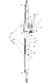
以下、ステアリングコラム装置の構成を説明する。図5に示すように、ステアリングコラム装置1は、ダッシュパネル2に設けられた挿通孔2aと、取付部3との2箇所で車体に支持されている。図4に示すように、ステアリングシャフト5は、中空のアッパシャフト5aと、該アッパシャフト5aの下部に図示しないスプライン結合部を介して軸方向へスライド自在に結合された中実のロアシャフト5bとから構成されている。そして、図5に示すようにアッパシャフト5aの上部にステアリングホィール4が取り付けられている。
Hereinafter, the configuration of the steering column device will be described. As shown in FIG. 5, the
前記ステアリングシャフト5を覆うジャケット6は、アッパジャケット6aと、該アッパジャケット6aの下部を覆うように設けられたロアジャケット6bとから構成されている。該ロアジャケット6bは、上部の第1ロアジャケット6cと、該第1ロアジャケット6cの下部に挿通された第2ロアジャケット6dとから構成されている。第1ロアジャケット6cと第2ロアジャケット6dとは、第1ロアジャケット6cの下部の内周面に突出形成した突起部7aを第2ロアジャケット6dの上部外周面に圧入嵌合することにより一体化されている。
The
アッパシャフト5aは上部に配置された軸受8aと下部に配置された軸受8bとを介してアッパジャケット6aの内部に回転自在に支持されている。ロアシャフト5bは、下部に配置された軸受8cを介して第2ロアジャケット6dの内部に回転自在に支持されている。アッパジャケット6aと第1ロアジャケット6cとの間およびアッパジャケット6aと第2ロアジャケット6dとの間には、テレスコ操作が円滑に行なわれるように樹脂スリーブ9(図4では樹脂スリーブ9は図示されていない),10が設けられている。図5に示すように、第2ロアジャケット6dの下部は、弾力性を有するブッシュ11を介してダッシュパネル2の挿通孔2aに挿入され、このブッシュ11を中心としてステアリングコラム装置1は揺動自在になっている。
The
ステアリングホイール4をアッパシャフト5aおよびアッパジャケット6aと共に上下方向にチルトさせたり、軸方向にテレスコさせることができるように、チルト・テレスコ機構部12が設けられている。以下、詳細に説明する。
A tilt /
図5に示した前記取付部3に固定される一対のサイドブラケット13,14は、図2に示すように略逆L字形に形成され、水平部分が取付座15を介して車体に離脱可能に取り付けられている。即ち、以下のように構成されている。取付座15は、孔15aに挿通させた図示しないボルトを介して車体の取付部3に結合されている。そして、取付座15の周囲に形成したスライド溝15bにサイドブラケット13,14の水平部分の内周縁13c,14cを車体前方から挿入した状態で樹脂孔15cおよび樹脂孔13d,14dに溶融した樹脂を流し込むことにより取付座15にサイドブラケット13,14が結合されている。取付座15の下面には、前記ボルトを孔34aに挿通させることによりエネルギー吸収部材34が結合されており、その先端の係合部34bがサイドブラケット13,14の切欠部13e,14eに係合している。車体の前方へ向かってサイドブラケット13,14に過大な荷重が加わったときには、樹脂孔15cおよび樹脂孔13d,14dに流し込んだ樹脂がせん断され、サイドブラケット13,14が車体前方へ向かって移動する際にエネルギー吸収部材34がガイドライン34cに沿って裂かれるように構成されている。
The pair of
サイドブラケット13,14の間には前記ステアリングシャフト5が配置されている。該ステアリングシャフト5を構成するアッパシャフト5aには、前記のようにアッパシャフト5aを回転自在に支持するアッパジャケット6aが設けられる一方、ロアシャフト5bには、該ロアシャフト5bを回転自在に支持するロアジャケット6bが設けられている。そして、アッパジャケット6aの下部がロアジャケット6bを構成する第1ロアジャケット6cの上部に挿入され、図3に示す摺動自在な重合部33を構成している。ここでは、アッパジャケット6aが重合部33の内筒を構成し、第1ロアジャケット6cが外筒を構成する。
The steering shaft 5 is disposed between the
アッパジャケット6aの下部の下面には断面略U字形のディスタンスブラケット16の上側の一対の結合部16cが溶接結合されている。該ディスタンスブラケット16の下側の両側には、ステアリングシャフト5の長さ方向に沿って長孔16a,16bが形成されている。また、前記一対のサイドブラケット13,14には、上下方向に沿って長孔13a,14aが形成されている。これらの長孔13a,14aと、長孔16a,16bとにはチルトボルト17が挿通されている。該チルトボルト17を介して一対のサイドブラケット13,14間を締め付けてディスタンスブラケット16を固定するために、締付手段18が設けられている。
A pair of
締付手段18の構成を以下に説明する。 The configuration of the tightening means 18 will be described below.
ディスタンスブラケット16の軸方向に長い長孔16aの幅寸法は前記チルトボルト17の外径寸法より少し大きく設定されている。一方、長孔16bの幅寸法はこれよりも更に大きく設定されており、長孔16bにはロックツース19の一部が嵌め込まれている。即ち、ロックツース19には突出部19a(図1)が形成され、該突出部19aには長孔16aと略同じ大きさの長孔19bが形成されている。そして、該長孔19bの外面の上下位置には、ラック状の歯19cが軸方向に沿って形成されている。ロックツース19は、突出部19aを長孔16bに嵌め込んだ状態で、ディスタンスブラケット16とサイドブラケット14との間に狭持されている。
The width dimension of the
次にサイドブラケット13,14の上下方向に長い2つの長孔13a,14aのうちの一方の長孔13aの幅寸法は、チルトボルト17の外径寸法より少し大きく設定されている。そして、他方の長孔14aの幅寸法は後述するカムツース20の突出部20a(図1)の外径寸法より少し大きく設定されている。
Next, the width dimension of one of the
カムツース20の前記突出部20a(図1)は長孔14aに嵌め込まれ、チルト位置の調整時には、カムツース20はチルトボルト17と共に上下方向にスライドし、カムツース20の両側位置がサイドブラケット14に圧接されることにより、アッパブラケット6aの上下方向位置(チルト調整位置)が決まる。そして、突出部20aの円形の面には、前記ラック状の歯19cと係合可能なラック状の歯(図示せず)が設けられ、これらの歯が噛み合うことによりアッパブラケット6aの軸方向位置(テレスコ調整位置)が決まる。そして、チルト・テレスコ調整時にロックツース19からカムツース20を強制的に離反させる略四角形の板ばね30が、サイドブラケット14とカムツース20との間に狭持されている。
The
一対のサイドブラケット13,14間の間隔を小さくしてディスタンスブラケット16を締め付けるため、サイドブラケット14の横には前記チルトボルト17が貫通した状態でカム機構22が設けられている。前記カム機構22は、前記カムツース20と一体成形された固定カム20bと、可動カム23とから構成されている。固定カム20bには、円周方向に沿って低部と、高部と、これらの低部と高部とを滑らかに繋ぐ斜面とが交互に複数組形成されている。一方、可動カム23には、固定カム20bの低部,斜面,高部に対して摺動する突出部が円周方向に沿って複数組形成されている。
In order to tighten the
可動カム23における突出部とは反対側の軸芯位置には凸部23aが形成され、該凸部23aは操作レバー21に形成された軸孔21aに異径嵌合されている。操作レバー21の軸孔21aの位置にはチルトボルト17の先端が貫通しており、該チルトボルト17にはロックナット24がねじ込まれている。ロックナット24を操作レバー21に結合し、かつ操作レバー21に対するロックナット24の回転位置を調整できるようにするため、ロックナット24が嵌まり込む六角孔25aを有するロックプレート25が設けられ、該六角孔25aを中心とする円弧状の長孔25bが形成されている。そして、該長孔25bに挿通させたボルト26が操作レバー21のねじ孔21bにねじ込まれている。操作レバー21を操作することにより、カム機構22の可動カム23を回動させることができる。
A
前記重合部33を構成する内筒と外筒との間には、前記のように樹脂スリーブ9が介在している。図3に示すように樹脂スリーブ9は、重合部33を構成する外筒としての第1ロアジャケット6cの内部に装着して設けられ、樹脂スリーブ9には樹脂スリーブ9から第1ロアジャケット6cの外部へ突出する突出部9aが設けられている。即ち、第1ロアジャケット6cの両側面には内外を貫通する貫通孔27が形成される一方、樹脂スリーブ9の外周面には円柱形の突出部9aが形成され、該突出部9aが貫通孔27に挿通されている。そして、図1に示すように貫通孔27から突出部9aの先端が突出し、該突出部9aの先端が一対のサイドブラケット13,14の内側面に当接している。このように外周面に突出部9aの形成された樹脂スリーブ9を弾性変形させて第1ロアジャケット6cの内部に挿入できるように、樹脂スリーブ9には軸方向に沿ってスリット9bが形成されている。
As described above, the
図2に示すように、第1ロアジャケット6cの上部の下面には支持ブラケット28が結合されている。支持ブラケット28は円弧状の取付部28aを有し、該取付部28aの右には前方へ向かって斜め下方へのびるフック部28bが形成され、該フック部28bの近傍には丸孔28cが形成されている。図1に示すように、フック部28bの斜め下方へのびる部分は、サイドブラケット13とディスタンスブラケット16との間に配置されており、フック部28bの先端から側方へ伸びる部分と一方のサイドブラケット13に形成されたフック部13bとの間に、保持バネ29が掛けられている。この保持バネ29は、チルト調節時に、ステアリングコラム装置1の上部がその重量によって下がらないように保持するものである。
As shown in FIG. 2, a
前記操作レバー21を回動操作することにより、固定カム20bの高部に可動カム23の突起部が位置する状態では、チルトボルト17がその先端部側へ向かって引張られるため、一対のサイドブラケット13,14によりディスタンスブラケット16が圧縮されて締付手段18を締め付けた状態となり、チルトロック状態になると共にロックツース19のラック状の歯19cとカムツース20のラック状の歯が係合し、ディスタンスブラケット16が拘束されてテレスコロック状態となる。
By rotating the
一方、操作レバー21を回動操作することにより、固定カム20bの低部に可動カム23の突起部が位置する状態では、チルトボルト17をその先端部側へ引っ張る力が解除され、ディスタンスブラケット16の圧縮が開放され、締付手段18を緩めた状態となる。これにより、板ばね30の付勢力によってロックツース19のラック状の歯19cとカムツース20のラック状の歯との係合が解除され、ディスタンスブラケット16が開放される。これによりディスタンスブラケット16は上下方向および軸方向のいずれの方向へも移動することができ、チルト調整およびテレスコ調整が可能になる。
On the other hand, when the
前記のようにディスタンスブラケット16が開放された状態でチルト調整する場合は、ステアリングホィール4を操作することにより、ディスタンスブラケット16を一対のサイドブラケット13,14間で上下方向へ移動させ、ステアリングホィール4の高さ調整を行なう。このとき、チルトボルト17は、長孔13a,14aの内部で移動し、ステアリングシャフト5は図5のブッシュ11を中心として揺動する。
When the tilt adjustment is performed with the
一方、前記のようにステアリングコラム装置が開放された状態でテレスコ調整する場合は、ステアリングホィール4を操作することにより、ディスタンスブラケット16を一対のサイドブラケット13,14間で軸方向へ移動させ、ステアリングホィール4の前後方向の調整を行なう。このとき、ディスタンスブラケット16が軸方向へ移動するので、チルトボルト17は動かないが、チルトボルト17が挿通された長孔16a,16bの部分が相対的に軸方向へ移動する。
On the other hand, when the telescopic adjustment is performed with the steering column device opened as described above, the
この発明によれば、重合部の外筒を構成する第1ロアジャケット6cの内部に樹脂スリーブ9を装着したので、テレスコ操作が行われる際に第1ロアジャケット6cに対するアッパジャケット6aの摺動が円滑に行われる。また、樹脂スリーブ9に形成され第1ロアジャケット6cの外部へ突出する突出部9aを一対のサイドブラケット13,14の内側面に当接させたので、突出部9aが第1ロアジャケット6cと一対のサイドブラケット13,14との間を埋める樹脂スペーサとして作用し、ステアリングシャフト5の車体左右方向の支持剛性が向上する。
According to the present invention, since the
この発明によれば、第1ロアジャケット6cに貫通孔27を形成し、樹脂スリーブ9に突出部9aを形成するだけなので、製作および組み立てが容易である。また、ロック時には一対のサイドブラケット13,14の内側面が突出部9aを内側へ押圧することで樹脂スリーブ9がアッパジャケット6aを締め付けるため、第1ロアジャケット6cとアッパジャケット6aとの重合部におけるアッパジャケット6aのガタの発生を防止できると共に、アッパジャケット6aの車体左右方向の支持剛性が向上する。
(b)実施の形態2
次に、実施の形態2を図6,図7に示す。実施の形態2は実施の形態1の一部を変更したものなので、同一部分には同一符号を付して説明を省略し、異なる部分のみを説明する。
According to the present invention, since the through
(B) Embodiment 2
Next, Embodiment 2 is shown in FIGS. Since the second embodiment is obtained by changing a part of the first embodiment, the same parts are denoted by the same reference numerals, the description thereof is omitted, and only different parts are described.
図のように、前記外筒を構成する第1ロアジャケット6cの内部で上方へ延長した軸方向内部延長部および半径方向の外側へ延長した半径方向延長部を構成するフランジ部32bが樹脂スリーブ32の上部に一体形成され、該フランジ部32bの相互に180度をなす両側位置から第1ロアジャケット6cの外部で下方へ戻るように延長した一対の軸方向外部延長部を構成する延長部が形成され、樹脂スリーブ32に延長部を兼用する突出部32cが形成されている。
As shown in the figure, a
この場合は、樹脂スリーブ32の外周面に突起部は存在しないので、樹脂スリーブ32の装着時に外径寸法を小さくして第1ロアジャケット6cの内部に押し込む必要はなく、実施の形態1で示すスリットは不要となる。また、樹脂スリーブ32の抜け止めとして、第1ロアジャケット6cの左右位置に貫通孔31が形成される一方、樹脂スリーブ32の突出部32cの内周面には円柱形の一対の突出部32aが軸心へ向かって突出形成されている。
In this case, since there is no protrusion on the outer peripheral surface of the
樹脂スリーブ32を第1ロアジャケット6cに装着する際には、突出部32cの先端を開いた状態で第1ロアジャケット6cの内部に樹脂スリーブ32を押し込み、一対の突出部32aを一対の貫通孔31に嵌合させる。
When the
この発明によれば、一対のサイドブラケット13,14に当接する突出部32cの面積を大きくできるので、ステアリングシャフト5の車体左右方向の支持剛性を更に向上させることができる。また、樹脂スリーブ32を第1ロアジャケット6cに挿入するという従来と変わらない作業で組み付けることができるため、組み付けの作業性が向上する。
一対のサイドブラケット13,14間での第1ロアジャケット6cの保持が強固に行われる。
According to the present invention, since the area of the protruding
The first
その他の構成,作用は実施の形態1と同じなので、説明を省略する。 Since other configurations and operations are the same as those of the first embodiment, description thereof is omitted.
なお、実施の形態1,2では、第1ロアジャケット6cの内部にアッパジャケット6aの下部が挿入されているので樹脂スリーブ32が装着される外筒は第1ロアジャケット6cとなるが、第1ロアジャケット6cをアッパジャケット6aの下部が覆う構成の場合は、樹脂スリーブ32が装着される外筒はアッパジャケット6aとなる。また、実施の形態1,2はチルト機構部とテレスコ機構部との双方を有するステアリングコラム装置に本発明を適用したものであるが、テレスコ機構部のみを有するステアリングコラム装置に本発明を適用することもできる。
In the first and second embodiments, since the lower portion of the
5…ステアリングシャフト
5a…アッパシャフト
5b…ロアシャフト
6a…アッパジャケット
6b…ロアジャケット
9…樹脂スリーブ
9a,32a…突出部
12…チルト・テレスコ機構部
13,14…サイドブラケット
16…ディスタンスブラケット
16b…長孔
17…チルトボルト
18…締付手段
27,31…貫通孔
32b…フランジ部(軸方向内部延長部,半径方向延長部)
32c…突出部(軸方向外部延長部)
33…重合部
5 ...
12 ... Tilt /
16 ... Distance bracket
16b ... long hole
17 ... Tilt bolt
18 ... Tightening means 27 , 31 ... Through
32c ... Projection (Axial external extension)
33 ... Polymerization part
Claims (2)
前記外筒には内外を貫通する一対の貫通孔を形成する一方、
前記樹脂スリーブの外周面には一対の突出部を形成し、
夫々の突出部を夫々の前記貫通孔に挿通させて前記外筒の外周面から突出させ、
前記外筒の外部へ突出する一対の突出部を前記一対のサイドブラケットの内側面に当接させたことを特徴とするステアリングコラム装置。 A pair of side brackets coupled to the vehicle body and projecting downward, and a lower shaft disposed between the pair of side brackets and an upper shaft that is movable in the axial direction relative to the lower shaft. A steering shaft configured; a lower jacket coupled to a vehicle body for rotatably supporting the lower shaft; an upper jacket for rotatably supporting the upper shaft; a lower portion of the upper jacket and an upper portion of the lower jacket; A superposed portion that slidably overlaps to form an outer cylinder and an inner cylinder, a resin sleeve interposed between the outer cylinder and the inner cylinder, and a long hole coupled to a lower portion of the upper jacket The pair of distance brackets and a pair of tilt bolts that pass through the pair of side brackets and are inserted into the long holes. A steering column device provided with a clamping means for tightening between side brackets bonded to the pair of side brackets the upper jacket telescopic capable,
While forming a pair of through-holes that penetrate the inside and outside of the outer cylinder,
A pair of protrusions are formed on the outer peripheral surface of the resin sleeve,
Each projecting portion is inserted through each of the through holes to project from the outer peripheral surface of the outer cylinder,
A steering column device, wherein a pair of projecting portions projecting to the outside of the outer cylinder are brought into contact with inner surfaces of the pair of side brackets.
前記外筒には内外を貫通する一対の貫通孔を形成する一方、
前記樹脂スリーブには、前記樹脂スリーブを前記外筒の内部で上方へ延長した軸方向内部延長部と、該軸方向内部延長部から半径方向での外側へ延長した半径方向延長部と、該半径方向延長部の相互に180度をなす両側位置から前記外筒の外部で下方へ戻るように延長した一対の軸方向外部延長部と、夫々の該軸方向外部延長部の内周面から軸心へ向かって突出形成され前記貫通孔に嵌合される一対の突出部とを形成し、
前記軸方向外部延長部を前記一対のサイドブラケットの内側面に当接させたことを特徴とするステアリングコラム装置。 A pair of side brackets coupled to the vehicle body and projecting downward, and a lower shaft disposed between the pair of side brackets and an upper shaft that is movable in the axial direction relative to the lower shaft. A steering shaft configured; a lower jacket coupled to a vehicle body for rotatably supporting the lower shaft; an upper jacket for rotatably supporting the upper shaft; a lower portion of the upper jacket and an upper portion of the lower jacket; A superposed portion that slidably overlaps to form an outer cylinder and an inner cylinder, a resin sleeve interposed between the outer cylinder and the inner cylinder, and a long hole coupled to a lower portion of the upper jacket The pair of distance brackets and a pair of tilt bolts that pass through the pair of side brackets and are inserted into the long holes. A steering column device provided with a clamping means for tightening between side brackets bonded to the pair of side brackets the upper jacket telescopic capable,
While forming a pair of through-holes that penetrate the inside and outside of the outer cylinder,
The resin sleeve is provided with axial internal extension of the resin sleeve was extended upward inside of the outer cylinder, the radial extension extending from said axial inner extension portion outwardly in the radial direction, the radius A pair of axial external extensions extended from both side positions of the directional extensions 180 degrees to return downward outside the outer cylinder, and axial centers from the inner peripheral surfaces of the respective axial external extensions Forming a pair of protrusions protruding toward and fitted into the through holes,
The steering column device according to claim 1, wherein the axially extending portion is in contact with the inner surfaces of the pair of side brackets.
Priority Applications (1)
| Application Number | Priority Date | Filing Date | Title |
|---|---|---|---|
| JP2006089707A JP4951258B2 (en) | 2006-03-29 | 2006-03-29 | Steering column device |
Applications Claiming Priority (1)
| Application Number | Priority Date | Filing Date | Title |
|---|---|---|---|
| JP2006089707A JP4951258B2 (en) | 2006-03-29 | 2006-03-29 | Steering column device |
Publications (2)
| Publication Number | Publication Date |
|---|---|
| JP2007261439A JP2007261439A (en) | 2007-10-11 |
| JP4951258B2 true JP4951258B2 (en) | 2012-06-13 |
Family
ID=38634852
Family Applications (1)
| Application Number | Title | Priority Date | Filing Date |
|---|---|---|---|
| JP2006089707A Expired - Fee Related JP4951258B2 (en) | 2006-03-29 | 2006-03-29 | Steering column device |
Country Status (1)
| Country | Link |
|---|---|
| JP (1) | JP4951258B2 (en) |
Families Citing this family (2)
| Publication number | Priority date | Publication date | Assignee | Title |
|---|---|---|---|---|
| JP5998552B2 (en) * | 2012-03-16 | 2016-09-28 | 日本精工株式会社 | Steering column device with telescopic mechanism |
| KR102124534B1 (en) * | 2014-06-12 | 2020-06-18 | 주식회사 만도 | Steering Column for Vehicle |
Family Cites Families (6)
| Publication number | Priority date | Publication date | Assignee | Title |
|---|---|---|---|---|
| JP4179049B2 (en) * | 2002-07-16 | 2008-11-12 | 日本精工株式会社 | Position-adjustable steering column device |
| AU2003252368A1 (en) * | 2002-09-04 | 2004-03-29 | Nsk Ltd. | Vehicle position adjustment type steering column device |
| JP4120375B2 (en) * | 2002-12-03 | 2008-07-16 | 日本精工株式会社 | Steering column device and manufacturing method thereof |
| JP4683456B2 (en) * | 2003-07-16 | 2011-05-18 | 日本精工株式会社 | Steering device |
| JP4390134B2 (en) * | 2003-11-05 | 2009-12-24 | 日本精工株式会社 | Steering device |
| JP4390135B2 (en) * | 2003-11-07 | 2009-12-24 | 日本精工株式会社 | Steering device |
-
2006
- 2006-03-29 JP JP2006089707A patent/JP4951258B2/en not_active Expired - Fee Related
Also Published As
| Publication number | Publication date |
|---|---|
| JP2007261439A (en) | 2007-10-11 |
Similar Documents
| Publication | Publication Date | Title |
|---|---|---|
| JP4938386B2 (en) | Movable steering device | |
| JP4932388B2 (en) | Movable steering device | |
| KR101031627B1 (en) | Steering column assembly | |
| JP3783524B2 (en) | Tilt and telescopic steering device | |
| WO2012035891A1 (en) | Steering device | |
| JP5708838B2 (en) | Steering device | |
| JP2003276614A (en) | Steering device | |
| WO2015064344A1 (en) | Steering device | |
| JP5595807B2 (en) | Steering column device | |
| JP6689692B2 (en) | Tightening device and steering device | |
| JP4791985B2 (en) | Steering column device | |
| JP2008105610A (en) | Steering device | |
| JP4951258B2 (en) | Steering column device | |
| JP2009018781A (en) | Steering column device | |
| JP2009051353A (en) | Position adjusting type steering device | |
| JP5019925B2 (en) | Steering column device | |
| US7500414B2 (en) | Steering column device for vehicle | |
| JP2009154789A (en) | Steering column unit | |
| JP2005138825A (en) | Steering column device | |
| JP2009137314A (en) | Position adjustment device for steering wheel | |
| JP5045255B2 (en) | Steering device | |
| JP2014015120A (en) | Electric power steering apparatus | |
| JP2007168625A (en) | Steering device | |
| JP2017154558A (en) | Steering device | |
| KR100375995B1 (en) | Tilting Lock for Automotive Steering Shaft |
Legal Events
| Date | Code | Title | Description |
|---|---|---|---|
| A621 | Written request for application examination |
Free format text: JAPANESE INTERMEDIATE CODE: A621 Effective date: 20081125 |
|
| A977 | Report on retrieval |
Free format text: JAPANESE INTERMEDIATE CODE: A971007 Effective date: 20110119 |
|
| A131 | Notification of reasons for refusal |
Free format text: JAPANESE INTERMEDIATE CODE: A131 Effective date: 20110802 |
|
| A521 | Written amendment |
Free format text: JAPANESE INTERMEDIATE CODE: A523 Effective date: 20110922 |
|
| TRDD | Decision of grant or rejection written | ||
| A01 | Written decision to grant a patent or to grant a registration (utility model) |
Free format text: JAPANESE INTERMEDIATE CODE: A01 Effective date: 20120306 |
|
| A01 | Written decision to grant a patent or to grant a registration (utility model) |
Free format text: JAPANESE INTERMEDIATE CODE: A01 |
|
| A61 | First payment of annual fees (during grant procedure) |
Free format text: JAPANESE INTERMEDIATE CODE: A61 Effective date: 20120312 |
|
| FPAY | Renewal fee payment (event date is renewal date of database) |
Free format text: PAYMENT UNTIL: 20150316 Year of fee payment: 3 |
|
| R150 | Certificate of patent or registration of utility model |
Free format text: JAPANESE INTERMEDIATE CODE: R150 |
|
| R250 | Receipt of annual fees |
Free format text: JAPANESE INTERMEDIATE CODE: R250 |
|
| LAPS | Cancellation because of no payment of annual fees |