JP4948596B2 - Automatic fluid supply mechanism for heated humidifier chamber - Google Patents
Automatic fluid supply mechanism for heated humidifier chamber Download PDFInfo
- Publication number
- JP4948596B2 JP4948596B2 JP2009506539A JP2009506539A JP4948596B2 JP 4948596 B2 JP4948596 B2 JP 4948596B2 JP 2009506539 A JP2009506539 A JP 2009506539A JP 2009506539 A JP2009506539 A JP 2009506539A JP 4948596 B2 JP4948596 B2 JP 4948596B2
- Authority
- JP
- Japan
- Prior art keywords
- float
- chamber
- ball
- seat
- fluid
- Prior art date
- Legal status (The legal status is an assumption and is not a legal conclusion. Google has not performed a legal analysis and makes no representation as to the accuracy of the status listed.)
- Expired - Fee Related
Links
- 239000012530 fluid Substances 0.000 title claims description 116
- 239000007788 liquid Substances 0.000 claims description 29
- 238000004891 communication Methods 0.000 claims description 6
- 230000000903 blocking effect Effects 0.000 claims description 3
- 230000000007 visual effect Effects 0.000 claims description 3
- XLYOFNOQVPJJNP-UHFFFAOYSA-N water Substances O XLYOFNOQVPJJNP-UHFFFAOYSA-N 0.000 description 24
- 238000013461 design Methods 0.000 description 5
- 238000012986 modification Methods 0.000 description 3
- 230000004048 modification Effects 0.000 description 3
- 238000005520 cutting process Methods 0.000 description 2
- 230000009977 dual effect Effects 0.000 description 2
- 230000005484 gravity Effects 0.000 description 2
- 230000002209 hydrophobic effect Effects 0.000 description 2
- 239000000463 material Substances 0.000 description 2
- 238000007789 sealing Methods 0.000 description 2
- 239000007787 solid Substances 0.000 description 2
- 229920000544 Gore-Tex Polymers 0.000 description 1
- 230000015572 biosynthetic process Effects 0.000 description 1
- -1 but not limited to Substances 0.000 description 1
- 239000002131 composite material Substances 0.000 description 1
- 238000010276 construction Methods 0.000 description 1
- 238000007796 conventional method Methods 0.000 description 1
- 230000003247 decreasing effect Effects 0.000 description 1
- 230000007812 deficiency Effects 0.000 description 1
- 230000001934 delay Effects 0.000 description 1
- 230000001419 dependent effect Effects 0.000 description 1
- 230000000694 effects Effects 0.000 description 1
- 239000011521 glass Substances 0.000 description 1
- 230000007774 longterm Effects 0.000 description 1
- 238000012423 maintenance Methods 0.000 description 1
- 238000004519 manufacturing process Methods 0.000 description 1
- 239000002184 metal Substances 0.000 description 1
- 238000000034 method Methods 0.000 description 1
- 229920003052 natural elastomer Polymers 0.000 description 1
- 229920001194 natural rubber Polymers 0.000 description 1
- 239000004033 plastic Substances 0.000 description 1
- 238000003825 pressing Methods 0.000 description 1
- 238000004513 sizing Methods 0.000 description 1
- 229920003051 synthetic elastomer Polymers 0.000 description 1
- 239000005061 synthetic rubber Substances 0.000 description 1
- 238000011144 upstream manufacturing Methods 0.000 description 1
Images


Classifications
-
- A—HUMAN NECESSITIES
- A61—MEDICAL OR VETERINARY SCIENCE; HYGIENE
- A61M—DEVICES FOR INTRODUCING MEDIA INTO, OR ONTO, THE BODY; DEVICES FOR TRANSDUCING BODY MEDIA OR FOR TAKING MEDIA FROM THE BODY; DEVICES FOR PRODUCING OR ENDING SLEEP OR STUPOR
- A61M16/00—Devices for influencing the respiratory system of patients by gas treatment, e.g. ventilators; Tracheal tubes
- A61M16/10—Preparation of respiratory gases or vapours
- A61M16/14—Preparation of respiratory gases or vapours by mixing different fluids, one of them being in a liquid phase
- A61M16/16—Devices to humidify the respiration air
- A61M16/162—Water-reservoir filling system, e.g. automatic
- A61M16/164—Water-reservoir filling system, e.g. automatic including a liquid inlet valve system
- A61M16/165—Water-reservoir filling system, e.g. automatic including a liquid inlet valve system with a float actuator
- A61M16/167—Water-reservoir filling system, e.g. automatic including a liquid inlet valve system with a float actuator acting vertically on the valve
-
- A—HUMAN NECESSITIES
- A61—MEDICAL OR VETERINARY SCIENCE; HYGIENE
- A61M—DEVICES FOR INTRODUCING MEDIA INTO, OR ONTO, THE BODY; DEVICES FOR TRANSDUCING BODY MEDIA OR FOR TAKING MEDIA FROM THE BODY; DEVICES FOR PRODUCING OR ENDING SLEEP OR STUPOR
- A61M16/00—Devices for influencing the respiratory system of patients by gas treatment, e.g. ventilators; Tracheal tubes
- A61M16/10—Preparation of respiratory gases or vapours
- A61M16/14—Preparation of respiratory gases or vapours by mixing different fluids, one of them being in a liquid phase
- A61M16/16—Devices to humidify the respiration air
- A61M16/162—Water-reservoir filling system, e.g. automatic
- A61M16/164—Water-reservoir filling system, e.g. automatic including a liquid inlet valve system
- A61M16/165—Water-reservoir filling system, e.g. automatic including a liquid inlet valve system with a float actuator
- A61M16/168—Water-reservoir filling system, e.g. automatic including a liquid inlet valve system with a float actuator having a dual float
-
- F—MECHANICAL ENGINEERING; LIGHTING; HEATING; WEAPONS; BLASTING
- F16—ENGINEERING ELEMENTS AND UNITS; GENERAL MEASURES FOR PRODUCING AND MAINTAINING EFFECTIVE FUNCTIONING OF MACHINES OR INSTALLATIONS; THERMAL INSULATION IN GENERAL
- F16K—VALVES; TAPS; COCKS; ACTUATING-FLOATS; DEVICES FOR VENTING OR AERATING
- F16K31/00—Actuating devices; Operating means; Releasing devices
- F16K31/12—Actuating devices; Operating means; Releasing devices actuated by fluid
- F16K31/18—Actuating devices; Operating means; Releasing devices actuated by fluid actuated by a float
- F16K31/20—Actuating devices; Operating means; Releasing devices actuated by fluid actuated by a float actuating a lift valve
-
- F—MECHANICAL ENGINEERING; LIGHTING; HEATING; WEAPONS; BLASTING
- F24—HEATING; RANGES; VENTILATING
- F24F—AIR-CONDITIONING; AIR-HUMIDIFICATION; VENTILATION; USE OF AIR CURRENTS FOR SCREENING
- F24F6/00—Air-humidification, e.g. cooling by humidification
- F24F6/02—Air-humidification, e.g. cooling by humidification by evaporation of water in the air
-
- A—HUMAN NECESSITIES
- A61—MEDICAL OR VETERINARY SCIENCE; HYGIENE
- A61M—DEVICES FOR INTRODUCING MEDIA INTO, OR ONTO, THE BODY; DEVICES FOR TRANSDUCING BODY MEDIA OR FOR TAKING MEDIA FROM THE BODY; DEVICES FOR PRODUCING OR ENDING SLEEP OR STUPOR
- A61M16/00—Devices for influencing the respiratory system of patients by gas treatment, e.g. ventilators; Tracheal tubes
- A61M16/10—Preparation of respiratory gases or vapours
- A61M16/1075—Preparation of respiratory gases or vapours by influencing the temperature
-
- Y—GENERAL TAGGING OF NEW TECHNOLOGICAL DEVELOPMENTS; GENERAL TAGGING OF CROSS-SECTIONAL TECHNOLOGIES SPANNING OVER SEVERAL SECTIONS OF THE IPC; TECHNICAL SUBJECTS COVERED BY FORMER USPC CROSS-REFERENCE ART COLLECTIONS [XRACs] AND DIGESTS
- Y10—TECHNICAL SUBJECTS COVERED BY FORMER USPC
- Y10T—TECHNICAL SUBJECTS COVERED BY FORMER US CLASSIFICATION
- Y10T137/00—Fluid handling
- Y10T137/0318—Processes
-
- Y—GENERAL TAGGING OF NEW TECHNOLOGICAL DEVELOPMENTS; GENERAL TAGGING OF CROSS-SECTIONAL TECHNOLOGIES SPANNING OVER SEVERAL SECTIONS OF THE IPC; TECHNICAL SUBJECTS COVERED BY FORMER USPC CROSS-REFERENCE ART COLLECTIONS [XRACs] AND DIGESTS
- Y10—TECHNICAL SUBJECTS COVERED BY FORMER USPC
- Y10T—TECHNICAL SUBJECTS COVERED BY FORMER US CLASSIFICATION
- Y10T137/00—Fluid handling
- Y10T137/6416—With heating or cooling of the system
- Y10T137/6579—Circulating fluid in heat exchange relationship
-
- Y—GENERAL TAGGING OF NEW TECHNOLOGICAL DEVELOPMENTS; GENERAL TAGGING OF CROSS-SECTIONAL TECHNOLOGIES SPANNING OVER SEVERAL SECTIONS OF THE IPC; TECHNICAL SUBJECTS COVERED BY FORMER USPC CROSS-REFERENCE ART COLLECTIONS [XRACs] AND DIGESTS
- Y10—TECHNICAL SUBJECTS COVERED BY FORMER USPC
- Y10T—TECHNICAL SUBJECTS COVERED BY FORMER US CLASSIFICATION
- Y10T137/00—Fluid handling
- Y10T137/7287—Liquid level responsive or maintaining systems
- Y10T137/7358—By float controlled valve
- Y10T137/7404—Plural floats
-
- Y—GENERAL TAGGING OF NEW TECHNOLOGICAL DEVELOPMENTS; GENERAL TAGGING OF CROSS-SECTIONAL TECHNOLOGIES SPANNING OVER SEVERAL SECTIONS OF THE IPC; TECHNICAL SUBJECTS COVERED BY FORMER USPC CROSS-REFERENCE ART COLLECTIONS [XRACs] AND DIGESTS
- Y10—TECHNICAL SUBJECTS COVERED BY FORMER USPC
- Y10T—TECHNICAL SUBJECTS COVERED BY FORMER US CLASSIFICATION
- Y10T137/00—Fluid handling
- Y10T137/7287—Liquid level responsive or maintaining systems
- Y10T137/7358—By float controlled valve
- Y10T137/742—In separate communicating float chamber
-
- Y—GENERAL TAGGING OF NEW TECHNOLOGICAL DEVELOPMENTS; GENERAL TAGGING OF CROSS-SECTIONAL TECHNOLOGIES SPANNING OVER SEVERAL SECTIONS OF THE IPC; TECHNICAL SUBJECTS COVERED BY FORMER USPC CROSS-REFERENCE ART COLLECTIONS [XRACs] AND DIGESTS
- Y10—TECHNICAL SUBJECTS COVERED BY FORMER USPC
- Y10T—TECHNICAL SUBJECTS COVERED BY FORMER US CLASSIFICATION
- Y10T137/00—Fluid handling
- Y10T137/7287—Liquid level responsive or maintaining systems
- Y10T137/7358—By float controlled valve
- Y10T137/7423—Rectilinearly traveling float
- Y10T137/7426—Float co-axial with valve or port
Landscapes
- Engineering & Computer Science (AREA)
- Health & Medical Sciences (AREA)
- General Engineering & Computer Science (AREA)
- General Health & Medical Sciences (AREA)
- Veterinary Medicine (AREA)
- Biomedical Technology (AREA)
- Heart & Thoracic Surgery (AREA)
- Hematology (AREA)
- Life Sciences & Earth Sciences (AREA)
- Animal Behavior & Ethology (AREA)
- Pulmonology (AREA)
- Public Health (AREA)
- Anesthesiology (AREA)
- Emergency Medicine (AREA)
- Mechanical Engineering (AREA)
- Chemical & Material Sciences (AREA)
- Combustion & Propulsion (AREA)
- Float Valves (AREA)
- Air Humidification (AREA)
- Check Valves (AREA)
Description
本発明は、一般に、流量および水位の自動制御装置に関し、特には、加熱式加湿器のチャンバにおける流体の液面を制御するのに特に適した流体自動供給機構に関する。 The present invention generally relates to an automatic flow rate and water level control device, and more particularly to an automatic fluid supply mechanism that is particularly suitable for controlling the fluid level in a chamber of a heated humidifier.
自動流量制御装置は、数千年とは言えないかもしれないが、少なくとも数百年にわたって存在している。自動流量制御装置の大部分は、専らリザーバまたはタンク内に所定の液面を維持するためのものである。そのような水位維持用の自動流量制御バルブは、多くの場合、所望の水位が得られたことを知らせるべく液体の表面に浮かぶ部材を取り入れている。おそらくは、最も有名な水位維持用の自動流量制御バルブは、手洗所またはトイレの貯水タンクにおいて見られる自動流量制御バルブである。水洗トイレのタンクの制御バルブは、フロートをレバーに取り付けて備えており、レバーが、水供給配管の遮断装置へと接続されている。タンク内の水が所望の水位まで上昇すると、フロートがレバーを、遮断装置を閉鎖して水の流れを遮断するように位置させる。 Automatic flow control devices may not be for thousands of years, but have existed for at least hundreds of years. The majority of automatic flow control devices are exclusively for maintaining a predetermined liquid level in a reservoir or tank. Such automatic flow control valves for maintaining the water level often incorporate a member that floats on the surface of the liquid to indicate that the desired water level has been achieved. Perhaps the most famous automatic flow control valve for maintaining the water level is the automatic flow control valve found in a lavatory or toilet water tank. The control valve of the flush toilet tank is provided with a float attached to a lever, which is connected to a shut-off device for the water supply pipe. When the water in the tank rises to the desired water level, the float positions the lever to close the shut-off device and shut off the water flow.
そのようなフロート/レバー式の制御装置は、比較的簡潔であるように見受けられるが、住宅所有者であれば承知のとおり、いくつかの問題を抱えている。さらに、フロート/レバー式の制御装置は、小規模の用途に向けた小型化にあまり適していない。さらに、提供される制御のレベルが比較的粗く、精密な水位の制御を必要とする用途に適していない。またさらに、ほぼ常に水面下にあるレバーに頼り、そのようなレバーが、少なくとも1つの位置において枢動しなければならないということが、厳しい用途にとって適切でない。このようなフロート/レバー式の制御装置を、米国特許第3049144号、同第5655232号、および同第5934881号に見つけることができる。 Such a float / lever control device appears to be relatively simple, but as homeowners know, it has several problems. Furthermore, the float / lever control device is not well suited for miniaturization for small scale applications. Furthermore, the level of control provided is relatively coarse and not suitable for applications that require precise water level control. Still further, it is not appropriate for demanding applications to rely on levers that are almost always below the surface and that such levers have to pivot in at least one position. Such float / lever control devices can be found in US Pat. Nos. 3,049,144, 5,655,232, and 5,934,881.
いくつかの自動流量制御装置は、フロート/レバー式の構成においてレバーがもたらす限界を認識し、フロートを繋ぎ止めない構成を取り入れている。そのような非繋留の構成を、米国特許第2169462号、同第2920644号、同第2928663号、および同第6129836号に見つけることができる。このような非繋留の設計の多くは、依然として、大きなサイズが必要であるという問題を抱えており、厳しい用途に適していない。 Some automatic flow control devices recognize the limitations that the lever provides in a float / lever configuration and incorporate a configuration that does not lock the float. Such non-tethered configurations can be found in U.S. Pat. Nos. 2,169,462, 2,920,644, 2,929,663, and 6,129,836. Many of these non-tethered designs still have the problem of requiring large sizes and are not suitable for demanding applications.
本発明は、2つの別個のチャンバを接続している座をまたいで協働する2つの自由運動部材を取り入れている。この構成は、自動流量制御装置の小型化ならびに堅実な動作能力を支援する一方で、リザーバ内の流体をきわめて高い精度で所定の水位に維持することができる。 The present invention incorporates two free motion members that cooperate across a seat connecting two separate chambers. This configuration supports the miniaturization of the automatic flow control device and the stable operation capability, while maintaining the fluid in the reservoir at a predetermined water level with extremely high accuracy.
本発明は、その最も一般的な構成において、種々の新規な機能によって技術水準を進歩させ、従来技術の装置の欠点の多くを新規な今までにない方法で克服する。本発明は、その最も一般的な意味で、いくつかの広く有効な構成のいずれかにて従来技術の欠点および限界を克服する。本発明は、そのような機能を実証し、新規な今までにない方法で従来の方法の欠点の多くを克服する。 The present invention advances the state of the art with a variety of novel features in its most common configuration and overcomes many of the disadvantages of prior art devices in a novel and unprecedented manner. The present invention, in its most general sense, overcomes the deficiencies and limitations of the prior art in any of several widely effective configurations. The present invention demonstrates such functionality and overcomes many of the disadvantages of conventional methods in a new and unprecedented way.
上記目的を達成するために、本発明は、加熱式加湿器のチャンバへの流体の流れを制御するための自動供給機構を含んでいる。自動供給機構は、第1の入口側チャンバと第1のフロートチャンバとを備える少なくとも第1のハウジングを画定している本体を含んでいる。第1の座は、第1の入口側チャンバと第1のフロートチャンバとの間の選択的な流体の連通を可能にする。第1のフロートチャンバに位置する第1のフロートと、第1の入口側チャンバに位置する第1のボールとが協働し、流体の第1の座の通過を許し、あるいは流体の第1の座の通過を阻止する。 To achieve the above object, the present invention includes an automatic supply mechanism for controlling the flow of fluid to the chamber of a heated humidifier. The automatic feed mechanism includes a body defining at least a first housing comprising a first inlet chamber and a first float chamber. The first seat allows selective fluid communication between the first inlet chamber and the first float chamber. The first float located in the first float chamber and the first ball located in the first inlet chamber cooperate to allow passage of the fluid through the first seat, or the fluid first Block the passage of the seat.
動作時、まず流体が、加圧下または重力によって第1の流体導入口に進入する。次いで、流体は、第1のボールが収容されている第1の入口側チャンバへと進む。流体は第1のチャンバを満たし、次いで、第1の座を通過することによって第1のフロートチャンバに進入する。次いで、流体は、側方へと移動して、第1の流体出口を介して第1のフロートチャンバを出る。次いで、流体は、一般に加湿器のチャンバを満たす。ここでは、第1のフロートが流体による作用を受けておらず、第1のフロートの重量によって、第1のボールが第1の座から離れた状態に保たれている。最終的に液面が充分に高く上昇すると、第1のボールに対する第1のフロートの作用が、第1のボールの浮力ならびに流体の圧力および/または速度からもたらされる他の流体の力によって打ち負かされるレベルまで低下する。その結果、第1のボールがボール支持部から離れるように移動し、第1のフロートの高さが上昇する。最後に、第1のボールが、第1の座に当接してシールを形成するのに充分に上昇し、流体の流れを停止させて、流体の高さを第1の所定の液面に維持する。 In operation, the fluid first enters the first fluid inlet under pressure or by gravity. The fluid then proceeds to the first inlet chamber in which the first ball is housed. The fluid fills the first chamber and then enters the first float chamber by passing through the first seat. The fluid then moves laterally and exits the first float chamber via the first fluid outlet. The fluid then generally fills the humidifier chamber. Here, the first float is not affected by the fluid, and the first ball is kept away from the first seat by the weight of the first float. Eventually, when the liquid level rises high enough, the action of the first float on the first ball is overcome by the buoyancy of the first ball and other fluid forces resulting from fluid pressure and / or velocity. The level drops to As a result, the first ball moves away from the ball support portion, and the height of the first float increases. Finally, the first ball is raised sufficiently to abut the first seat to form a seal, stopping the flow of fluid and maintaining the fluid level at the first predetermined level. To do.
さらに、本発明は、自動供給機構に冗長性またはフェイルセーフを導入すべく、第2の自動供給システムを取り入れている2連ハウジングの実施形態を含む。この実施形態においては、自動供給機構は、第1のハウジングおよび第2のハウジングの両者を画定する本体を含んでいる。第2のハウジングの構成要素は、第1のハウジングの構成要素と実質的に同一である。第2のハウジングの構成は、第1のハウジングと同一であってよく、第1のフロートチャンバのベース面の高さが第2のフロートチャンバのベース面の高さに等しくてよいが、第1のハウジングの故障を観察者に知らせるようにハウジングを構成することが好ましい。すなわち、冗長システムが機能しなければならない事態において生じる液面が、第1のシステムが適正に機能している場合に生じる液面と相違し、故障の知らせをもたらす。 Furthermore, the present invention includes a dual housing embodiment that incorporates a second automatic supply system to introduce redundancy or failsafe in the automatic supply mechanism. In this embodiment, the automatic feed mechanism includes a body that defines both a first housing and a second housing. The components of the second housing are substantially the same as the components of the first housing. The configuration of the second housing may be the same as the first housing, and the height of the base surface of the first float chamber may be equal to the height of the base surface of the second float chamber. Preferably, the housing is configured to inform the observer of the failure of the housing. That is, the liquid level that occurs in situations where the redundant system must function is different from the liquid level that occurs when the first system is functioning properly, resulting in a failure notification.
本発明によれば、2つの別個のチャンバを接続している座をまたいで協働する2つの自由運動部材を取り入れたことにより、自動流量制御装置の小型化ならびに堅実な動作能力を支援する一方で、リザーバ内の流体をきわめて高い精度で所定の水位に維持することが可能となる。 In accordance with the present invention, by incorporating two free-moving members that cooperate across a seat connecting two separate chambers, the automatic flow control device is miniaturized and supports a solid operating capability. Thus, the fluid in the reservoir can be maintained at a predetermined water level with extremely high accuracy.
本発明の実施の形態の好ましい特徴について添付の図面を参照して以下に説明する。ただし、本発明は種々の変形が可能であり、これらの実施形態に限定するものではなく、請求項によってのみ限定される。また、添付の全ての図面において、同様の構成要素に対しては同じ参照番号を付している。図面は本発明を例示的に示すものであり、本発明の範囲を限定するものではない。 Preferred features of embodiments of the present invention will be described below with reference to the accompanying drawings. However, the present invention can be modified in various ways and is not limited to these embodiments, and is limited only by the claims. In all the attached drawings, the same reference numerals are assigned to the same components. The drawings illustrate the invention by way of example and do not limit the scope of the invention.
本発明の加熱式加湿器チャンバの流体自動供給機構(10)は、技術水準における大きな前進を可能にする。本装置の好ましい実施形態は、独自かつ新規な方法で構成される部材の新規な今までにない配置であって、従来は得られなかった好ましくかつ望ましい能力を示す配置によって、これを達成する。図面に関連して以下に記載される詳細な説明は、あくまで本発明の現時点において好ましい実施形態の説明を目的とするものであり、本発明の構築または利用の唯一の形態を示しているわけではない。説明においては、設計、機能、手段、および本発明の実施の方法を、図示の実施形態に関連して記載する。しかしながら、同じまたは同等の機能および特徴を、別の実施形態によって達成することも可能であり、そのような実施形態も、本発明の技術的思想および技術的範囲に包含されることを、理解すべきである。 The heated humidifier chamber fluid auto-feed mechanism (10) of the present invention allows a significant advance in the state of the art. A preferred embodiment of the device accomplishes this by a new and unprecedented arrangement of components constructed in a unique and novel way, which exhibits a desirable and desirable capability not previously obtained. The detailed description set forth below in connection with the drawings is for purposes of illustrating the presently preferred embodiment of the invention and is not intended to represent the only form of construction or use of the invention. Absent. In the description, the design, functions, means, and methods of practicing the invention are described in connection with the illustrated embodiments. However, it will be understood that the same or equivalent functions and features may be achieved by other embodiments, and such embodiments are also encompassed within the spirit and scope of the present invention. Should.
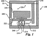
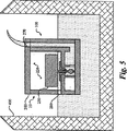
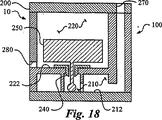
全般的に図1〜17に関して示すように、本発明は、加熱式加湿器のチャンバへの流体の流れを制御するための自動供給機構(10)である。図面が比例尺ではないことに留意されたい。実際、加熱式加湿器のチャンバにおいて使用されるであろう自動供給機構は、大いに拡大されている。さらに、導入口および排出口は、ボールが着座するまでチャンバからの空気の排出が可能であるような寸法でなければならないことを、当業者であれば理解できるであろう。また別の実施形態では、第1のチャンバに疎水性の通気孔を配置してもよい。これらの通気孔は、当業者にとって周知であり、好ましい疎水性の通気孔は、この業界において見られるGore−Tex(登録商標)である。自動供給機構(10)は、図1に示すように、第1の入口側チャンバ(210)と第1のフロートチャンバ(220)とを備える第1のハウジング(200)を少なくとも画定している本体(100)を含んでいる。第1のフロート(250)および第1のボール(230)と協働する第1の座(240)は、第1の入口側チャンバ(210)と第1のフロートチャンバ(220)との間の選択的な流体の連通を可能にする。 As shown generally with respect to FIGS. 1-17, the present invention is an automatic supply mechanism (10) for controlling the flow of fluid to a chamber of a heated humidifier. Note that the drawings are not to scale. In fact, the automatic feeding mechanism that would be used in a heated humidifier chamber is greatly expanded. Furthermore, those skilled in the art will appreciate that the inlet and outlet must be dimensioned such that air can be exhausted from the chamber until the ball is seated. In another embodiment, a hydrophobic vent may be disposed in the first chamber. These vents are well known to those skilled in the art and the preferred hydrophobic vent is Gore-Tex® found in the industry. The automatic supply mechanism (10), as shown in FIG. 1, has a body defining at least a first housing (200) comprising a first inlet chamber (210) and a first float chamber (220). (100) is included. A first seat (240) cooperating with the first float (250) and the first ball (230) is between the first inlet chamber (210) and the first float chamber (220). Allows selective fluid communication.
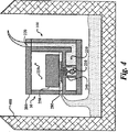
次に、自動供給機構(10)の基本動作を簡単に説明し、次いで自動供給機構(10)の種々の構成要素を詳細に開示する。さらに図1を参照すると、まず流体が、加圧下または重力によって第1の流体導入口(270)に進入する。次いで、流体は、第1のボール(230)が収容されている第1の入口側チャンバ(210)へと進む。流体が第1のチャンバ(210)を満たし、次いで、第1のフロート(250)の一部分によって部分的に封鎖されている第1の座(240)を通過することによって、第1のフロートチャンバ(220)に進入する。次いで、流体は、側方へと移動して、第1の流体出口(280)を介して第1のフロートチャンバ(220)から流出する。次いで、流体は、一般に、加湿器のチャンバ(400)を満たす。この自動供給機構(10)の最初の充填が、図4に示されている。 Next, the basic operation of the automatic supply mechanism (10) will be briefly described, and then the various components of the automatic supply mechanism (10) will be disclosed in detail. Still referring to FIG. 1, the fluid first enters the first fluid inlet (270) under pressure or by gravity. The fluid then proceeds to the first inlet chamber (210) in which the first ball (230) is housed. The fluid fills the first chamber (210) and then passes through a first seat (240) that is partially sealed by a portion of the first float (250), thereby causing the first float chamber ( 220). The fluid then moves laterally and out of the first float chamber (220) via the first fluid outlet (280). The fluid then generally fills the humidifier chamber (400). The initial filling of this automatic feed mechanism (10) is shown in FIG.
自動供給機構(10)の構造のいくつかの態様を、この機構(10)の動作の流れに移る前に、復習しておくべきである。先ず初めに、第1の入口側チャンバ(210)は、図1に最もよく示すように、第1の入口側チャンバ(210)の床または底部と考えることができる入口側チャンバベース面(212)を有している。 Some aspects of the structure of the automatic feed mechanism (10) should be reviewed before moving on to the operational flow of the mechanism (10). Initially, the first inlet chamber (210) may be considered the floor or bottom of the first inlet chamber (210), as best shown in FIG. have.
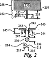
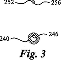
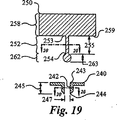
第2に、第1の座(240)は、図2の分解図に最もよく示されているように、第1のフロートチャンバ(220)へと開口している遠位端(243)と第1の入口側チャンバ(210)へと開口している近位端(244)とを備える第1の座チャネル(242)を有している。遠位端(243)から近位端(244)までの距離が、第1のチャネル長さ(245)を規定している。さらに、第1の座チャネル(242)は、図2の切断線3−3に沿って得た第1の座チャネル(242)の断面図を表している図3に示されている開口断面積(246)を有している。 Second, the first seat (240) has a distal end (243) and a first end that open to the first float chamber (220), as best shown in the exploded view of FIG. A first seat channel (242) with a proximal end (244) opening into one inlet chamber (210). The distance from the distal end (243) to the proximal end (244) defines a first channel length (245). Further, the first seat channel (242) is an open cross-sectional area shown in FIG. 3 representing a cross-sectional view of the first seat channel (242) taken along section line 3-3 of FIG. (246).
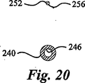
第3に、第1のフロート(250)は、図2に示すように、第1のフロートチャンバ(220)に位置するフロート部(258)と、第1の座(240)に向かって突き出して、第1の座チャネル(242)に実質的に平行であるステム部(252)とを有している。第1のフロートチャンバ(220)は、第1のフロート(250)が流体および/または第1のボール(230)の作用を受けてチャンバ(220)内で運動できるように構成されている。さらに、ステム部(252)は、第1のフロート(250)の動きにつれて第1の座チャネル(242)内を動くことができるように、第1の座(240)と協働している。ステム部(252)は、フロート部(258)への接続部に位置する遠位端(253)と、第1の座(240)に最も近い近位端(254)を有しており、遠位端(253)と近位端(254)との間の距離が、ステム長さ(255)を規定している。ステム部(252)は、第1の座チャネルの開口断面積(246)よりも小さいステム断面積(256)を有しており、ステム部(252)が第1の座チャネル(242)内にあるときでも、流体が第1の座チャネル(242)を通って流れることができる。 Third, the first float (250) protrudes toward the first seat (240) and the float portion (258) located in the first float chamber (220) as shown in FIG. And a stem portion (252) that is substantially parallel to the first seat channel (242). The first float chamber (220) is configured to allow the first float (250) to move within the chamber (220) under the action of fluid and / or the first ball (230). Further, the stem portion (252) cooperates with the first seat (240) such that it can move within the first seat channel (242) as the first float (250) moves. The stem portion (252) has a distal end (253) located at the connection to the float portion (258) and a proximal end (254) closest to the first seat (240); The distance between the distal end (253) and the proximal end (254) defines the stem length (255). The stem portion (252) has a stem cross-sectional area (256) that is smaller than the opening cross-sectional area (246) of the first seat channel, and the stem portion (252) is within the first seat channel (242). At some point, fluid can flow through the first seat channel (242).
第4に、第1のボール(230)は直径(232)を有しており、第1のボール(230)の中心が第1のフロートのステム部(252)の中心軸とほぼ同一直線上にあるように、第1の入口側チャンバ(210)に位置している。すでに述べたように、第1のボール(230)に第1のフロートのステム部(252)が作用しており、図6に見られるように、第1のフロート(250)が浮かび始めて第1のボール(230)への作用が小さくなって、第1のボール(230)がボール支持部(214)から離れて浮かび上がることができる所定の液面に達するまで、あるいは第1のボール(230)の浮力および流体の力が第1のフロート(250)の作用を上回って第1のボール(230)を第1の座(240)から離れるように動かすまで、第1のボール(230)をボール支持部(214)に押し付けている。ボール支持部(214)は、入口側チャンバベース面(212)から支持部長さ(217)だけ延びている突起であり、第1の入口側チャンバ(210)へと進入する流体が、第1のボール(230)を過ぎ、ステム部(252)の周囲で第1の座(240)を通過することによって、第1のフロートチャンバ(220)および第1の流体出口(280)へと出ることができるようにしている。最終的に、液面は、図7に見られるように、所定の第1の流体高さ(500)に達したときに、第1のボール(230)に対する第1のフロート(250)の作用が減少し、第1のボール(230)がボール支持部(214)から浮かび上がって第1の座チャネルの近位端(244)を閉じ、第1の入口側チャンバ(210)から第1のフロートチャンバ(220)への流体の流れを阻止して、流体の流れを停止させる。 Fourth, the first ball (230) has a diameter (232), and the center of the first ball (230) is substantially collinear with the central axis of the stem portion (252) of the first float. In the first inlet chamber (210). As already mentioned, the stem portion (252) of the first float acts on the first ball (230), and the first float (250) starts to float as shown in FIG. Until the first ball (230) reaches a predetermined liquid level at which the first ball (230) can float away from the ball support (214) or until the first ball (230) reaches the predetermined liquid level. ) Buoyancy and fluid forces exceed the action of the first float (250) to move the first ball (230) away from the first seat (240). It is pressed against the ball support (214). The ball support portion (214) is a protrusion that extends from the inlet side chamber base surface (212) by the length of the support portion (217), and the fluid that enters the first inlet side chamber (210) Passing the first seat (240) past the ball (230) and around the stem (252) exits to the first float chamber (220) and the first fluid outlet (280). I can do it. Eventually, the liquid level reaches the predetermined first fluid height (500), as seen in FIG. 7, and the action of the first float (250) on the first ball (230). , And the first ball (230) emerges from the ball support (214) to close the proximal end (244) of the first seat channel and from the first inlet chamber (210) to the first Blocking fluid flow to the float chamber (220) stops the fluid flow.
次に、再び動作の流れを図4を参照して説明すると、第1の入口側チャンバ(210)の最初の充填を示しており、第1のフロート(250)は、流体による作用を受けておらず、第1のフロート(250)の重量が、第1のボール(230)をボール支持部(214)に押し付けて、第1の座(240)から離れた状態に維持している。当業者であれば理解できるとおり、第1のボール(230)をボール支持部(214)に押し付けられた状態に保つために、第1のボール(230)の重量が、第1のボール(230)が完全に沈むことによって生じる浮力およびあらゆる流体の力に打ち勝たなければならない。 Next, the flow of operation will be described again with reference to FIG. 4, showing the initial filling of the first inlet chamber (210), where the first float (250) is acted upon by the fluid. In other words, the weight of the first float (250) keeps the first ball (230) away from the first seat (240) by pressing the first ball (230) against the ball support (214). As will be appreciated by those skilled in the art, the weight of the first ball (230) is sufficient to keep the first ball (230) pressed against the ball support (214). ) Must overcome the buoyancy and all fluid forces caused by the complete sinking.
次に、図5はその後の状況を示しており、今や流体が、第1の入口側チャンバ(210)を満たし、加湿器のチャンバ(400)および第1のフロートチャンバ(220)を図2に示されているフロート部の底面(259)の通常の高さまで満たしている。この流体の高さにおいて第1のフロート(250)が浮き始めるか否かは、第1のフロート(250)の構成に依存して決まる。中空の第1のフロート(250)または低密度の第1のフロート(250)は、この高さにおいて浮かぶ可能性がある一方で、中実の第1のフロート(250)または高密度の第1のフロート(250)は、浮き始めるために流体の高さがより高くなければならないであろう。しかしながら、本発明の動作は、第1のフロート(250)が実際に浮くことに依存しているのではなく、第1のボール(230)が第1の座(240)と協働して流体の流れを停止させることができるように、第1のボール(230)への作用が減少することに依存していることに、注意することが重要である。したがって、第1のフロート(250)は、釣り合いおもりとして機能し、第1のボール(230)の浮力および存在するあらゆる流体の力に対抗しさえすればよい。さらに、第1のフロート(250)および第1のボール(230)の密度、ならびに第1のフロート(250)および第1のボール(230)のサイズおよび形状は、予想される水位および圧力の範囲に対応するように変更が可能である。 Next, FIG. 5 shows the subsequent situation, where the fluid now fills the first inlet chamber (210) and the humidifier chamber (400) and the first float chamber (220) in FIG. It fills to the normal height of the bottom (259) of the float shown. Whether or not the first float (250) begins to float at this fluid level depends on the configuration of the first float (250). The hollow first float (250) or the low density first float (250) may float at this height, while the solid first float (250) or the high density first The float (250) would have to have a higher fluid height to begin to float. However, the operation of the present invention does not depend on the actual float of the first float (250), but the first ball (230) cooperates with the first seat (240) to achieve fluid flow. It is important to note that the action on the first ball (230) is dependent on decreasing so that the flow of the water can be stopped. Thus, the first float (250) functions as a counterweight and only needs to counter the buoyancy of the first ball (230) and any fluid forces present. In addition, the density of the first float (250) and the first ball (230), and the size and shape of the first float (250) and the first ball (230) are within the expected water level and pressure range. It can be changed to correspond to
図6は、第1のボール(230)がボール支持部(214)から離れるように移動し、第1のフロート(250)の高さが上昇している次の水位を示している。最後に、図7は、第1のボール(230)が第1の座(240)に当接して位置して、流体の流れを停止させ、流体の高さを第1の所定の液面(500)に維持している状態を示している。 FIG. 6 shows the next water level when the first ball (230) has moved away from the ball support (214) and the height of the first float (250) has increased. Finally, FIG. 7 shows that the first ball (230) is positioned in contact with the first seat (240) to stop the flow of fluid, and the height of the fluid is adjusted to a first predetermined level ( 500).
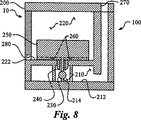
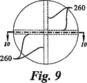
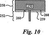
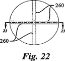
再び図1および2を参照すると、特定の一実施形態においては、入口側チャンバベース面(212)から第1の座チャネルの遠位端(243)までの垂直距離が、支持部長さ(217)、第1のボールの直径(232)、およびステム長さ(255)の合計よりも小さい。この実施形態は、フロート部の底面(259)が第1の座チャネル(242)を遮断することがないように保証し、第1のフロートチャンバ(220)への流体の流入を容易にするために、第1の座チャネルの近位端(244)とフロート部の底面(259)との間にすき間が存在することを保証する。図8、9、および10に見られる代替の実施形態においては、入口側チャンバベース面(212)から第1の座チャネルの遠位端(243)までの垂直距離が、支持部長さ(217)、第1のボールの直径(232)、およびステム長さ(255)の合計に実質的に等しく、フロート部の底面(259)に、第1の座チャネル(242)から第1のフロートチャンバ(220)への流体の流入を促進するために、少なくとも1つの流路(260)が形成されている。この実施形態においては、第1のフロート部の底面(259)が第1の座(240)に直接的に当接しうるが、流体は、第1の座チャネル(242)から出て少なくとも1つの流路(260)へと入り、第1のフロートチャンバ(220)へと導かれるため、流体の流れが妨げられることがない。 Referring again to FIGS. 1 and 2, in one particular embodiment, the vertical distance from the inlet chamber base surface (212) to the distal end (243) of the first seat channel is the support length (217). Less than the sum of the diameter of the first ball (232) and the stem length (255). This embodiment ensures that the bottom surface (259) of the float part does not block the first seat channel (242) and facilitates the inflow of fluid into the first float chamber (220). To ensure that there is a gap between the proximal end (244) of the first seat channel and the bottom surface (259) of the float. In the alternative embodiment seen in FIGS. 8, 9, and 10, the vertical distance from the inlet chamber base surface (212) to the distal end (243) of the first seat channel is the support length (217). Substantially equal to the sum of the diameter of the first ball (232) and the stem length (255), from the first seat channel (242) to the first float chamber ( 220), at least one flow path (260) is formed. In this embodiment, the bottom surface (259) of the first float portion can directly contact the first seat (240), but the fluid exits the first seat channel (242) and has at least one Since it enters the flow path (260) and is guided to the first float chamber (220), the flow of fluid is not hindered.
再び図1および2を参照すると、第1のフロート(250)、第1の座(240)、第1のボール(230)、およびボール支持部(214)の間の協働が不可欠である。すでに開示したとおり、第1のボール(230)の中心は、第1のフロートのステム部(252)の中心軸と実質的に同一直線にある。さらなる実施形態においては、ボール支持部(214)は、第1のボール(230)の中心およびステム部(252)の中心軸と実質的に同一直線にある。ボール支持部(214)は、一般に第1の入口側チャンバのベース面(212)から突き出していると説明したが、当業者であれば、第1の入口側チャンバのベース面(212)に形成された凹部であってもよく、あるいは単に第1のボール(230)の運動を制御するための狭く制限された領域であってもよいことを理解できるであろう。 Referring again to FIGS. 1 and 2, cooperation between the first float (250), the first seat (240), the first ball (230), and the ball support (214) is essential. As already disclosed, the center of the first ball (230) is substantially collinear with the central axis of the stem portion (252) of the first float. In a further embodiment, the ball support (214) is substantially collinear with the center of the first ball (230) and the central axis of the stem (252). Although it has been described that the ball support portion (214) generally protrudes from the base surface (212) of the first inlet side chamber, those skilled in the art will be able to form the base surface (212) of the first inlet side chamber. It will be appreciated that it may be a recessed portion that is formed, or simply a narrowly confined area for controlling the movement of the first ball (230).
第1のフロートのステム部(252)は、第1の座チャネル(242)に離脱可能に収容されるが、依然としてステム部(252)と座チャネル(242)との間の流体の流れを許すように設計されている。したがって、図3に見られるように、ステムの断面積(256)は、第1の座チャネルの開口の断面積(246)よりも小さくなければならない。特定の一実施形態においては、ステムの断面積(256)は、第1の座チャネルの開口の断面積(246)よりも、少なくとも10パーセント小さい。 The stem portion (252) of the first float is removably received in the first seat channel (242), but still allows fluid flow between the stem portion (252) and the seat channel (242). Designed to be Thus, as seen in FIG. 3, the stem cross-sectional area (256) must be smaller than the cross-sectional area (246) of the first seat channel opening. In one particular embodiment, the cross-sectional area (256) of the stem is at least 10 percent less than the cross-sectional area (246) of the first seat channel opening.
さらに、第1の座チャネルの遠位端(244)は、第1のボール(230)が第1の座(240)に当接して液体を通さない密封(シール)構造が形成されるように保証するため、第1のボール(230)と協働するように構成されていなければならない。したがって、特定の一実施形態においては、第1の座チャネルの近位端(244)における第1の座チャネルの開口の断面積(246)は、第1のボール(230)の最大の断面積よりも少なくとも10パーセント小さい。「ボール」という用語が使用されているが、第1のボール(230)は必ずしも球形である必要はなく、実際には、第1のフロート(250)によって変位させることが可能であって第1の座(240)に当接してシールを生成する任意の物体でよいことは、当業者であれば理解できるであろう。実際、第1のボール(230)は、これらに限られるわけではないが、円錐形あるいはフィルムまたはディスクなどの平坦な形状など、事実上あらゆる幾何学的形状であってよい。 Further, the distal end (244) of the first seat channel is such that the first ball (230) abuts the first seat (240) to form a sealing structure that prevents liquid from passing therethrough. To ensure, it must be configured to cooperate with the first ball (230). Thus, in one particular embodiment, the cross-sectional area (246) of the first seat channel opening at the proximal end (244) of the first seat channel is the maximum cross-sectional area of the first ball (230). Less than at least 10 percent. Although the term “ball” is used, the first ball (230) does not necessarily have to be spherical, and in fact can be displaced by the first float (250) Those skilled in the art will appreciate that any object that abuts the seat (240) to create a seal may be used. In fact, the first ball (230) may be virtually any geometric shape, such as, but not limited to, a conical shape or a flat shape such as a film or disk.
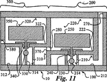
すでに図1〜10の実施形態を開示したので、次に2連ハウジングの実施形態を開示する。図11〜17を全般的に参照すると、この実施形態は、本発明の自動供給機構(10)に冗長性またはフェイルセーフを導入するための第2の自動供給システムを取り入れている。この実施形態においては、自動供給機構(10)は、第1のハウジング(200)および第2のハウジング(300)を画定する本体(100)を備えている。第2のハウジング(300)の構成要素は、第1のハウジング(200)の構成要素と実質的に同一であり、200番台ではなくて300番台の参照符号を有しており、構成要素の説明において、第1のハウジング(200)の構成要素に組み合わせられている「第1の」という言葉ではなくて、「第2の」という言葉が取り入れられている。したがって、ここで、第1のハウジング(200)に関する先の開示を繰り返すことはせず、図1、2、および3に代わる図11、12、および13ならびに第2のハウジング(300)の構成要素に関して、第1のハウジング(200)に関する先の開示を援用する。 Having already disclosed the embodiment of FIGS. 1-10, the embodiment of the dual housing will now be disclosed. Referring generally to FIGS. 11-17, this embodiment incorporates a second automatic supply system for introducing redundancy or failsafe into the automatic supply mechanism (10) of the present invention. In this embodiment, the automatic feed mechanism (10) includes a body (100) that defines a first housing (200) and a second housing (300). The components of the second housing (300) are substantially the same as the components of the first housing (200) and have reference numbers in the 300s instead of the 200s. , The term “second” is incorporated rather than the term “first” combined with the components of the first housing (200). Accordingly, the previous disclosure relating to the first housing (200) will not be repeated here, but instead of FIGS. 11, 12, and 13 and the components of the second housing (300) in place of FIGS. With respect to, the previous disclosure relating to the first housing (200) is incorporated.
第2のハウジング(300)の構成は、第1のハウジング(200)と同一であってよく、第1のフロートチャンバのベース面(222)の高さが第2のフロートチャンバのベース面(322)の高さに等しくてよいが、第1のハウジング(200)の故障を観察者に知らせるようにハウジング(200、300)を構成することが好ましい。したがって、図11および12に見られるように、第2のフロートチャンバのベース面(322)の高さが、第1のフロートチャンバのベース面(222)よりも高く、第2のボール支持部の長さ(317)が、第1のボール支持部の長さ(217)よりも大きく、したがって第1の液面(500)よりも高さの高い第2の液面(600)が設定され、第1のハウジング(200)の構成部品が適切に機能していない旨の視覚的な通知をもたらす。この実施形態においては、第1の流体出口(280)が、第2の流体導入口(370)に連通している。第1のフロートの故障を、第2のフロートチャンバのベースを高めることによって達成される高めの水位によって知らせることができる。この高めの水位を、第2のフロートの構成を変えることによって達成することも可能である。これは、浮力への影響を変化させ、したがって第2のフロートの上昇を遅らせ、チャンバ内により高い水位をもたらす。この自動供給の設計は、座の上流の直接的な流路にボールを配置するため、供給バッグ内の水位が高いことに起因する漏れに抵抗する。換言すると、典型的な設計においては、水バッグが高いほど、より大きな水圧が座へと加わり、座を封じている機構が押しのけられる可能性が大きくなる。この設計によれば、より大きな水圧がむしろ反対に作用し、ボールを座へとさらに押し付ける。結果として、加湿器のチャンバが水を受け取ることがなく、患者がバッグの水によって水浸しにならないように保証される。 The configuration of the second housing (300) may be the same as that of the first housing (200), and the height of the base surface (222) of the first float chamber is the base surface (322) of the second float chamber. ), But the housing (200, 300) is preferably configured to inform the observer of a failure of the first housing (200). Thus, as seen in FIGS. 11 and 12, the height of the base surface (322) of the second float chamber is higher than the base surface (222) of the first float chamber and the second ball support A second liquid level (600) is set, the length (317) being greater than the length (217) of the first ball support, and thus higher than the first liquid level (500); Provides a visual notification that the components of the first housing (200) are not functioning properly. In this embodiment, the first fluid outlet (280) communicates with the second fluid inlet (370). The failure of the first float can be signaled by the higher water level achieved by raising the base of the second float chamber. It is also possible to achieve this higher water level by changing the configuration of the second float. This changes the effect on buoyancy and thus delays the rise of the second float, resulting in a higher water level in the chamber. This self-feeding design places the ball in a direct flow path upstream of the seat and resists leakage due to high water levels in the supply bag. In other words, in a typical design, the higher the water bag, the more water pressure is applied to the seat and the greater the chance that the mechanism sealing the seat will be displaced. According to this design, higher water pressure acts rather the opposite, pushing the ball further onto the seat. As a result, the humidifier chamber does not receive water, ensuring that the patient is not submerged by the bag water.
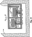
次に、動作の流れについて述べると、図14は、第1の入口側チャンバ(210)および第2の入口側チャンバ(310)の最初の充填を示しており、第1のフロート(250)および第2のフロート(350)は、流体による作用を受けておらず、第1のフロート(250)の重量が、第1のボール(230)を第1のボール支持部(214)に押し付けて、第1の座(240)から離れた状態に維持しており、第2のフロート(350)の重量が、第2のボール(330)を第2のボール支持部(314)に押し付けて、第2の座(340)から離れた状態に維持している。当業者であれば理解できるとおり、第1のボール(230)をボール支持部(214)に押し付けられた状態に保つために、第1のボール(230)の重量が、第1のボール(230)が完全に沈むことによって生じる浮力およびあらゆる流体の力に打ち勝たなければならない。 Turning now to the operational flow, FIG. 14 shows the initial filling of the first inlet side chamber (210) and the second inlet side chamber (310), the first float (250) and The second float (350) is not affected by the fluid and the weight of the first float (250) presses the first ball (230) against the first ball support (214), Maintaining a distance from the first seat (240), the weight of the second float (350) presses the second ball (330) against the second ball support (314) and It is kept away from the two seats (340). As will be appreciated by those skilled in the art, the weight of the first ball (230) is sufficient to keep the first ball (230) pressed against the ball support (214). ) Must overcome the buoyancy and all fluid forces caused by the complete sinking.
次に、図15は、第1のハウジング(200)の構成部品が適切に機能しており、第1のボール(230)が第1の座(240)を通過する流体の流れを停止させて、第1の液面(500)を維持している状況を示している。この状況において、液面は、第2のボール(330)に対する第2のフロート(350)の作用を第2のボール(330)が第2のボール支持部(314)を離れる点まで軽減するほどには充分に高まっていない。 Next, FIG. 15 shows that the components of the first housing (200) are functioning properly and the first ball (230) stops the flow of fluid through the first seat (240). The state which maintains the 1st liquid level (500) is shown. In this situation, the liquid level reduces the action of the second float (350) on the second ball (330) to the point where the second ball (330) leaves the second ball support (314). It has not increased enough.
図16は、妨害物(I)が第1のボール(230)と第1の座(240)との間に引っかかり、第1のボール(230)が第1の座(240)に当接してシールを形成することを妨げている状況を示している。そのような状況において、液面は、第2のハウジング(300)が存在しないならば、非制御の様相で上昇を続けるであろう。ここでは、液面が上昇し、図16に見られるように、第2のフロート(350)によって第2のボール(330)へと加えられる力が減少することで、第2のボール(330)の浮力によって打ち負かされて、第2のボール(330)が第2のボール支持部(314)から離れる。最終的に、液面が第2の液面(600)に達すると、第2のボール(330)が、第2の座チャネルの近位端(344)を閉じる。図17に見られる第2の液面(600)と第1の液面(500)との間の高さの差が、自動供給機構(10)が適切に機能しておらず、保守が必要である旨の知らせを、作業者へともたらす。通常の液面の変化を検出して、故障を通知するために、任意の数の聴覚、視覚、および触覚警報表示器を、自動供給機構(10)へと取り入れることができる。 FIG. 16 shows that the obstruction (I) is caught between the first ball (230) and the first seat (240), and the first ball (230) comes into contact with the first seat (240). It shows the situation preventing the formation of a seal. In such a situation, the liquid level will continue to rise in an uncontrolled manner if the second housing (300) is not present. Here, the liquid level rises and, as can be seen in FIG. 16, the force applied to the second ball (330) by the second float (350) is reduced to thereby reduce the second ball (330). The second ball (330) is separated from the second ball support (314) by being defeated by the buoyancy. Eventually, when the liquid level reaches the second liquid level (600), the second ball (330) closes the proximal end (344) of the second seat channel. The difference in height between the second liquid level (600) and the first liquid level (500) seen in FIG. 17 indicates that the automatic supply mechanism (10) is not functioning properly and requires maintenance. To the operator. Any number of audible, visual, and tactile alarm indicators can be incorporated into the automatic delivery mechanism (10) to detect normal liquid level changes and notify of failure.
添付の図面に示した加湿器のチャンバ(400)は、あくまで概念的な性質のものにすぎないことを、当業者であれば理解できるであろう。さらに、自動供給機構(10)およびその構成部品を、例えばこれらに限られるわけではないが、金属、プラスチック、ガラス、天然および合成ゴム、ならびにさまざまな種類の複合材料など、さまざまな流体における動作にとって望ましい特定の特性を反映するように選択される幅広くさまざまな材料から製造することができる。 Those skilled in the art will appreciate that the humidifier chamber (400) shown in the accompanying drawings is merely conceptual in nature. In addition, the automatic feed mechanism (10) and its components are for operation in a variety of fluids such as, but not limited to, metal, plastic, glass, natural and synthetic rubber, and various types of composite materials. It can be made from a wide variety of materials selected to reflect the specific properties desired.
本明細書に開示した好ましい実施形態について、多数の変更、変形、および変種が当業者にとって明らかであり、それらはすべて、本発明の技術的思想および技術的範囲に包含される。例えば、特定の実施形態を詳しく説明したが、先の実施形態および変形が、さまざまな種類の代替物、ならびに/あるいは追加または代替の材料、構成要素の相対配置、および寸法設定を取り入れるように変更可能であることを、当業者であれば理解できるであろう。したがって、本明細書においては、本発明のいくつかの変形例しか説明されていないが、そのような追加の変更および変形例ならびにそれらの均等物を実施することが、以下の特許請求の範囲に記載される本発明の技術的思想および技術的範囲に含まれることを、理解すべきである。 Numerous changes, modifications, and variations of the preferred embodiments disclosed herein will be apparent to those skilled in the art and are all encompassed within the spirit and scope of the present invention. For example, while specific embodiments have been described in detail, previous embodiments and variations have been modified to incorporate various types of alternatives, and / or additional or alternative materials, relative placement of components, and sizing One skilled in the art will understand that this is possible. Accordingly, while only certain modifications of the invention have been described herein, it is within the scope of the following claims to implement such additional changes and modifications and equivalents thereof. It should be understood that they are within the spirit and scope of the invention as described.
この加熱式加湿器のチャンバの自動供給機構は、レバー動作の流量制御システムに一般的に伴う諸問題を取り除く新規な流量制御装置を求める長期にわたるニーズに応えるものである。この機構は、一部には可動部品の数が少ないという理由で、製造および組み立てが容易である。単純な構成が、従来技術の自動供給装置に対する大きな前進をもたらしている。さらに、本発明の種々の構成部品を、機構の動作パラメータを調節すべく容易に交換することができ、これは従来技術にはない特徴である。 This automatic humidifier chamber supply mechanism addresses the long-term need for a new flow control device that eliminates the problems commonly associated with lever-operated flow control systems. This mechanism is easy to manufacture and assemble, partly because of the small number of moving parts. The simple configuration provides a major advance over prior art automatic feeders. Furthermore, the various components of the present invention can be easily replaced to adjust the operating parameters of the mechanism, a feature not found in the prior art.
10 自動供給機構、 100 本体、 210 入口側チャンバ、 220 フロートチャンバ、 230 ボール、 240 座、 250 フロート、 270 導入口、 280 出口 10 automatic supply mechanism, 100 body, 210 inlet side chamber, 220 float chamber, 230 ball, 240 seat, 250 float, 270 inlet, 280 outlet
Claims (11)
入口側チャンバベース面(212)を備える第1の入口側チャンバ(210)と、第1のフロートチャンバ(220)とを有する第1のハウジング(200)を画定し、前記第1の入口側チャンバ(210)は、該第1の入口側チャンバ(210)に流入する流体が通過する第1の流体導入口(270)を有し、前記第1のフロートチャンバ(220)は、該第1のフロートチャンバ(220)から流出する流体が通過する第1の流体出口(280)を有している本体(100)と、
前記第1の入口側チャンバ(210)と前記第1のフロートチャンバ(220)との間の流体の連通を促進する第1の座(240)であって、前記第1のフロートチャンバ(220)へと開口している遠位端(243)と前記第1の入口側チャンバ(210)へと開口している近位端(244)と開口断面積(246)とを有する第1の座チャネル(242)を有しており、前記遠位端(243)から前記近位端(244)までの距離が第1のチャネル長さ(245)を規定している第1の座(240)と、
前記第1のフロートチャンバ(220)に位置するフロート部(258)と、前記第1の座(240)に向かって突き出し、前記第1の座チャネル(242)に実質的に平行であるステム部(252)と、を有する第1のフロート(250)であって、前記第1のフロートチャンバ(220)は、作用を受けたときの前記フロート(250)が前記第1のフロートチャンバ(220)内を自由に動くことができるように構成されており、前記ステム部(252)は、前記第1のフロート(250)の動きにつれて前記第1の座チャネル(242)内を動くことができるように前記第1の座(240)と協働し、前記ステム部(252)は、前記フロート部(258)への接続部にある遠位端(253)と前記第1の座(240)に最も近い近位端(254)とを有しており、前記遠位端(253)と前記近位端(254)との間の距離が、ステム長さ(255)を規定しており、前記ステム部(252)が、前記第1の座チャネルの開口断面積(246)よりも小さいステム断面積(256)を有することで、前記ステム部(252)が前記第1の座チャネル(242)内にあるときに、流体が第1の座チャネル(242)を通って流れることができるように構成された第1のフロート(250)と、
直径(232)を有しており、前記第1の入口側チャンバ(210)に位置し、中心が前記ステム部(252)の中心軸と実質的に同一直線上にあるように構成されている第1のボール(230)と、を備え、
前記第1のボール(230)は、前記第1のフロートのステム部(252)による作用を受けて、前記入口側チャンバベース面(212)から支持部長さ(217)だけ延びているボール支持部(214)に押し付けられることで、前記第1の入口側チャンバ(210)に進入する流体が、前記第1のボール(230)を通過し、前記ステム部(252)の周囲の前記第1の座(240)を通過することによって前記第1のフロートチャンバ(220)および前記第1の流体出口(280)へと流出することでき、
流体レベルが所定の第1の液面(500)に達することによって、前記第1のボール(230)への前記ステム部(252)の作用が減じられ、前記第1のボール(230)が前記ボール支持部(214)から離れて浮き上がって前記第1の座チャネルの近位端(244)をシールし、前記第1の入口側チャンバ(210)から前記第1のフロートチャンバ(220)への流体の流れを阻止して、前記流体の流れを止めることができる自動供給機構(10)。An automatic supply mechanism (10) for controlling fluid flow in a chamber of a heated humidifier, comprising:
A first housing (200) having a first inlet chamber (210) with an inlet chamber base surface (212) and a first float chamber (220) is defined, said first inlet chamber (210) has a first fluid inlet (270) through which fluid flowing into the first inlet chamber (210) passes, and the first float chamber (220) A body (100) having a first fluid outlet (280) through which fluid exiting the float chamber (220) passes;
A first seat (240) that facilitates fluid communication between the first inlet chamber (210) and the first float chamber (220), the first float chamber (220); A first seat channel having a distal end (243) opening to the front, a proximal end (244) opening to the first inlet chamber (210), and an open cross-sectional area (246) A first seat (240) having a distance from the distal end (243) to the proximal end (244) defining a first channel length (245); ,
A float portion (258) located in the first float chamber (220) and a stem portion protruding toward the first seat (240) and substantially parallel to the first seat channel (242); (252), wherein the first float chamber (220) is acted upon when the float (250) is acted upon by the first float chamber (220). The stem (252) is configured to move within the first seat channel (242) as the first float (250) moves. In cooperation with the first seat (240), the stem portion (252) is connected to the distal end (253) and the first seat (240) at the connection to the float portion (258). Nearest An end (254), and a distance between the distal end (253) and the proximal end (254) defines a stem length (255), and the stem portion (252) ) Has a stem cross-sectional area (256) that is smaller than the opening cross-sectional area (246) of the first seat channel so that the stem portion (252) is in the first seat channel (242) A first float (250) configured to allow fluid to flow through the first seat channel (242);
It has a diameter (232), is located in the first inlet chamber (210), and is configured such that its center is substantially collinear with the central axis of the stem portion (252). A first ball (230),
The first ball (230) is extended by a support portion length (217) from the inlet-side chamber base surface (212) under the action of the stem portion (252) of the first float. (214), the fluid entering the first inlet-side chamber (210) passes through the first ball (230), and the first portion around the stem portion (252) is pressed. Can pass through the seat (240) to the first float chamber (220) and the first fluid outlet (280);
When the fluid level reaches a predetermined first liquid level (500), the action of the stem portion (252) on the first ball (230) is reduced, and the first ball (230) is Lifts away from the ball support (214) to seal the proximal end (244) of the first seat channel and from the first inlet chamber (210) to the first float chamber (220) An automatic supply mechanism (10) capable of stopping the flow of the fluid by blocking the flow of the fluid.
前記第2の入口側チャンバ(310)と前記第2のフロートチャンバ(320)との間の流体の連通を促進する第2の座(340)であって、前記第2のフロートチャンバ(320)へと開口している遠位端(343)と、前記第2の入口側チャンバ(310)へと開口している近位端(344)と、開口断面積(346)とを有する第2の座チャネル(342)を有しており、前記遠位端(343)から前記近位端(344)までの距離が第2のチャネル長さ(345)を規定している第2の座(340)と、
前記第2のフロートチャンバ(320)に位置するフロート部(358)と、前記第2の座(340)に向かって突き出し、前記第2の座チャネル(342)に実質的に平行であるステム部(352)と、を有する第2のフロート(350)であって、前記第2のフロートチャンバ(320)が、作用を受けたときの前記第2のフロート(350)が前記第1のフロートチャンバ(220)内を自由に動くことができるように構成されており、前記ステム部(352)が、前記第2のフロート(350)の動きにつれて前記第2の座チャネル(342)内を動くことができるように前記第2の座(340)と協働し、前記ステム部(352)が、前記フロート部(358)への接続部にある遠位端(353)と前記第2の座(340)に最も近い近位端(354)とを有しており、前記遠位端(353)と前記近位端(354)との間の距離が、ステム長さ(355)を規定しており、前記ステム部(352)が、前記第2の座チャネルの開口断面積(346)よりも小さいステム断面積(356)を有することで、前記ステム部(352)が前記第2の座チャネル(342)内にあるときに、流体が第2の座チャネル(342)を通って流れることができるように構成された第2のフロート(350)と、
直径(332)を有しており、前記第2の入口側チャンバ(310)に位置しており、中心が前記ステム部(352)の中心軸と実質的に同一直線上にあるように構成されている第2のボール(330)とをさらに備えており、
前記第2のボール(330)が、前記第2のフロートのステム部(352)による作用を受けて、前記入口側チャンバベース面(312)から支持部長さ(317)だけ延びているボール支持部(314)に押し付けられることで、前記第1の入口側チャンバ(310)に進入する流体が、前記第2のボール(330)を通過し、前記ステム部(352)の周囲の前記第2の座(340)を通過することによって前記第2のフロートチャンバ(320)および前記第2の流体出口(380)へと出ることでき、
流体レベルが所定の第2の液面(600)に達することによって、前記第2のボール(330)への前記ステム部(352)の作用が減じられ、前記第2のボール(330)が前記ボール支持部(314)から離れて浮き上がって前記第2の座チャネルの近位端(344)をシールし、前記第2の入口側チャンバ(310)から前記第2のフロートチャンバ(320)への流体の流れを阻止して、前記流体の流れを止めることができる、請求項1に記載の自動供給機構(10)。A second inlet chamber (310) located on the body (100) and having an inlet chamber base surface (312); and a second float chamber (320); The inlet chamber (310) has a second fluid inlet (370) through which fluid entering the second inlet chamber (310) passes, the second float chamber (320) being A second housing (300) having a second fluid outlet (380) through which fluid exiting the second float chamber (320) passes;
A second seat (340) that facilitates fluid communication between the second inlet chamber (310) and the second float chamber (320), the second float chamber (320) A second end having a distal end (343) that opens to the side, a proximal end (344) that opens to the second inlet chamber (310), and an open cross-sectional area (346). A second seat (340) having a seat channel (342), the distance from the distal end (343) to the proximal end (344) defining a second channel length (345); )When,
A float portion (358) located in the second float chamber (320), and a stem portion protruding toward the second seat (340) and substantially parallel to the second seat channel (342) (352), wherein the second float (350) when the second float chamber (320) is acted upon is the first float chamber. (220) configured to move freely within the second seat channel (342) as the stem (352) moves with the movement of the second float (350). In cooperation with the second seat (340) so that the stem portion (352) is connected to the distal end (353) and the second seat (at the connection to the float portion (358)). 340) most A proximal end (354), and a distance between the distal end (353) and the proximal end (354) defines a stem length (355), the stem The portion (352) has a stem cross-sectional area (356) that is smaller than the opening cross-sectional area (346) of the second seat channel, so that the stem portion (352) is in the second seat channel (342). A second float (350) configured to allow fluid to flow through the second seat channel (342) when
Having a diameter (332), located in the second inlet chamber (310), and configured such that a center is substantially collinear with a central axis of the stem portion (352). And a second ball (330),
A ball support portion in which the second ball (330) extends from the inlet-side chamber base surface (312) by a support portion length (317) under the action of the stem portion (352) of the second float. (314), the fluid entering the first inlet chamber (310) passes through the second ball (330), and the second portion around the stem portion (352). Can pass through the seat (340) to the second float chamber (320) and the second fluid outlet (380);
When the fluid level reaches a predetermined second liquid level (600), the action of the stem portion (352) on the second ball (330) is reduced, and the second ball (330) is Lifts away from the ball support (314) to seal the proximal end (344) of the second seat channel and from the second inlet chamber (310) to the second float chamber (320) The automatic supply mechanism (10) of claim 1, wherein the fluid flow can be blocked to stop the fluid flow.
1)第1のハウジング(200)と第2のハウジング(300)とを画定している本体(100)であって、
a)前記第1のハウジング(200)は、第1の入口側チャンバベース面(212)を備える第1の入口側チャンバ(210)と、第1のフロートチャンバ(220)とを有しており、前記第1の入口側チャンバ(210)は、該第1の入口側チャンバ(210)に流入する流体が通過する第1の流体導入口(270)を有し、前記第1のフロートチャンバ(220)は、該第1のフロートチャンバ(220)から流出する流体が通過する第1の流体出口(280)を有しており、
b)前記第2のハウジング(300)は、第2の入口側チャンバベース面(312)を備える第2の入口側チャンバ(310)と、第2のフロートチャンバ(320)とを有しており、前記第2の入口側チャンバ(310)は、該第2の入口側チャンバ(310)に流入する流体が通過する第2の流体導入口(370)を前記第1の流体出口(280)に連通させて有し、前記第2のフロートチャンバ(320)は、該第2のフロートチャンバ(320)から流出する流体が通過する第2の流体出口(380)を有している、本体(100)と、
2)前記第1の入口側チャンバ(210)と前記第1のフロートチャンバ(220)との間の流体の連通を促進する第1の座(240)であって、前記第1のフロートチャンバ(220)へと開口している第1のチャネル遠位端(243)と、前記第1の入口側チャンバ(210)へと開口している第1のチャネル近位端(244)と、第1の開口断面積(246)とを有する第1の座チャネル(242)を有しており、前記第1のチャネル遠位端(243)から前記第1のチャネル近位端(244)までの距離が第1のチャネル長さ(245)を規定している第1の座(240)と、
3)前記第2の入口側チャンバ(310)と前記第2のフロートチャンバ(320)との間の流体の連通を促進する第2の座(340)であって、前記第2のフロートチャンバ(320)へと開口している第2のチャネル遠位端(343)と、前記第2の入口側チャンバ(310)へと開口している第2のチャネル近位端(344)と、第2の開口断面積(346)とを有する第2の座チャネル(342)を有しており、前記第2のチャネル遠位端(343)から前記第2のチャネル近位端(344)までの距離が第2のチャネル長さ(345)を規定している第2の座(340)と、
4)前記第1のフロートチャンバ(220)に位置する第1のフロート部(258)と、前記第1の座(240)に向かって突き出し、前記第1の座チャネル(242)に実質的に平行である第1のステム部(252)と、を有する第1のフロート(250)であって、前記第1のフロートチャンバ(220)は、作用を受けたときの前記第1のフロート(250)が前記第1のフロートチャンバ(220)内を自由に動くことができるように構成されており、前記第1のステム部(252)は、前記第1のフロート(250)の動きにつれて前記第1の座チャネル(242)内を動くことができるように前記第1の座(240)と協働し、前記第1のステム部(252)は、前記フロート部(258)への接続部にある第1の遠位端(253)と前記第1の座(240)に最も近い第1の近位端(254)とを有しており、前記第1の遠位端(253)と前記第1の近位端(254)との間の距離が、第1のステム長さ(255)を規定しており、前記第1のステム部(252)は、前記第1の座チャネルの開口断面積(246)よりも小さい第1のステム断面積(256)を有することで、前記第1のステム部(252)が前記第1の座チャネル(242)内にあるときに、流体が第1の座チャネル(242)を通って流れることができるように構成された第1のフロート(250)と、
5)前記第2のフロートチャンバ(320)に位置する第2のフロート部(358)と、前記第2の座(340)に向かって突き出し、前記第2の座チャネル(342)に実質的に平行である第2のステム部(352)と、を有する第2のフロート(350)であって、前記第2のフロートチャンバ(320)は、作用を受けたときの前記第2のフロート(350)が前記第1のフロートチャンバ(220)内を自由に動くことができるように構成されており、前記第2のステム部(352)は、前記第2のフロート(350)の動きにつれて前記第2の座チャネル(342)内を動くことができるように前記第2の座(240)と協働し、前記第2のステム部(352)は、前記第2のフロート部(358)への接続部にある第2の遠位端(353)と前記第2の座(340)に最も近い第2の近位端(354)とを有しており、前記第2の遠位端(353)と前記第2の近位端(354)との間の距離が、第2のステム長さ(355)を規定しており、前記第2のステム部(352)は、前記第2の座チャネルの開口断面積(346)よりも小さい第2のステム断面積(356)を有することで、前記第2のステム部(352)が前記第2の座チャネル(342)内にあるときに、流体が第2の座チャネル(342)を通って流れることができるように構成された第2のフロート(350)と、
6)第1の直径(232)を有しており、前記第1の入口側チャンバ(210)に位置して、中心が前記第1のステム部(252)の中心軸と実質的に同一直線上にあるように構成されている第1のボール(230)、および
7)第2の直径(332)を有しており、前記第2の入口側チャンバ(310)に位置して、中心が前記第2のステム部(352)の中心軸と実質的に同一直線上にあるように構成されている第2のボール(330)と、を備えており、
前記第1のボール(230)は、前記第1のフロートのステム部(252)による作用を受けて、前記第1の入口側チャンバベース面(212)から第1の支持部長さ(217)だけ延びている第1のボール支持部(214)に押し付けられることで、前記第1の入口側チャンバ(210)に流入する流体が、前記第1のボール(230)を通過し、前記第1のステム部(252)の周囲の前記第1の座(240)を通過することによって前記第1のフロートチャンバ(220)および前記第1の流体出口(280)へと出ることができ、
流体レベルが所定の第1の液面(500)に達することによって、前記第1のボール(230)への前記第1のステム部(252)の作用が減じられ、前記第1のボール(230)が前記第1のボール支持部(214)から離れて浮き上がって前記第1の座チャネルの近位端(244)をシールし、前記第1の入口側チャンバ(210)から前記第1のフロートチャンバ(220)への流体の流れを阻止して、前記流体の流れを止めることができ、
前記第2のボール(330)は、前記第2のフロートのステム部(352)による作用を受けて、前記第2の入口側チャンバベース面(312)から第2の支持部長さ(317)だけ延びている第2のボール支持部(314)に押し付けられることで、前記第2の入口側チャンバ(310)に進入する流体が、前記第2のボール(330)を通過し、前記第2のステム部(352)の周囲の前記第2の座(340)を通過することによって前記第2のフロートチャンバ(220)および前記第2の流体出口(380)へと出ることができ、
流体レベルが所定の第2の液面(600)に達することによって、前記第2のボール(330)への前記第2のステム部(352)の作用が減じられ、前記第2のボール(330)が前記第2のボール支持部(314)から離れて浮き上がって前記第2の座チャネルの近位端(344)をシールし、前記第2の入口側チャンバ(310)から前記第2のフロートチャンバ(220)への流体の流れを阻止して、前記流体の流れを止めることができる自動供給機構(10)。In an automatic supply mechanism (10) for controlling fluid flow in a chamber of a heated humidifier,
1) a body (100) defining a first housing (200) and a second housing (300),
a) The first housing (200) has a first inlet chamber (210) with a first inlet chamber base surface (212) and a first float chamber (220). The first inlet-side chamber (210) has a first fluid inlet (270) through which a fluid flowing into the first inlet-side chamber (210) passes, and the first float chamber (210) 220) has a first fluid outlet (280) through which fluid exiting the first float chamber (220) passes;
b) The second housing (300) has a second inlet chamber (310) with a second inlet chamber base surface (312) and a second float chamber (320). The second inlet chamber (310) has a second fluid inlet (370) through which the fluid flowing into the second inlet chamber (310) passes to the first fluid outlet (280). The second float chamber (320) has a second fluid outlet (380) through which a fluid flowing out of the second float chamber (320) passes. )When,
2) a first seat (240) that facilitates fluid communication between the first inlet chamber (210) and the first float chamber (220), the first float chamber ( A first channel distal end (243) that opens to 220), a first channel proximal end (244) that opens to said first inlet chamber (210), and a first A first seat channel (242) having an open cross-sectional area (246) and a distance from the first channel distal end (243) to the first channel proximal end (244) A first seat (240) defining a first channel length (245);
3) a second seat (340) that facilitates fluid communication between the second inlet chamber (310) and the second float chamber (320), wherein the second float chamber ( 320) a second channel distal end (343) opening to the second inlet side chamber (310), a second channel proximal end (344) opening to the second inlet chamber (310), and a second A second seat channel (342) having an open cross-sectional area (346) and a distance from the second channel distal end (343) to the second channel proximal end (344) A second seat (340) defining a second channel length (345);
4) a first float portion (258) located in the first float chamber (220) and protruding towards the first seat (240) and substantially into the first seat channel (242); A first float (250) having a first stem portion (252) that is parallel to the first float chamber (220) when the first float chamber (220) is acted upon. ) Can move freely in the first float chamber (220), and the first stem portion (252) can be moved in accordance with the movement of the first float (250). Cooperating with the first seat (240) so as to be able to move in one seat channel (242), the first stem portion (252) being connected to the float portion (258) A first distal end (25 ) And a first proximal end (254) closest to the first seat (240), the first distal end (253) and the first proximal end (254) The first stem length (255) defines a first stem length (255), and the first stem portion (252) is smaller than the opening cross-sectional area (246) of the first seat channel. 1 stem cross-sectional area (256) so that when the first stem portion (252) is in the first seat channel (242), fluid passes through the first seat channel (242). A first float (250) configured to be able to flow
5) a second float portion (358) located in the second float chamber (320) and protruding towards the second seat (340) and substantially into the second seat channel (342) A second float (350) having a second stem portion (352) that is parallel to the second float chamber (320) when the second float chamber (320) is acted upon. ) Can move freely in the first float chamber (220), and the second stem portion (352) can be moved in accordance with the movement of the second float (350). Cooperating with the second seat (240) to be able to move in two seat channels (342), the second stem portion (352) is connected to the second float portion (358). Second distal end at connection 353) and a second proximal end (354) closest to the second seat (340), the second distal end (353) and the second proximal end (354). ) Defines a second stem length (355), the second stem portion (352) being smaller than the opening cross-sectional area (346) of the second seat channel Having a second stem cross-sectional area (356) allows fluid to flow through the second seat channel (342) when the second stem portion (352) is in the second seat channel (342). A second float (350) configured to be able to flow through;
6) It has a first diameter (232) and is located in the first inlet chamber (210), and its center is substantially the same axis as the central axis of the first stem portion (252). A first ball (230) configured to be in line, and 7) a second diameter (332), located in the second inlet chamber (310) and centered A second ball (330) configured to be substantially collinear with a central axis of the second stem portion (352),
The first ball (230) is affected by the stem portion (252) of the first float, and only the first support portion length (217) from the first inlet-side chamber base surface (212). By being pressed against the extending first ball support (214), the fluid flowing into the first inlet-side chamber (210) passes through the first ball (230), and the first ball support (214) Can pass through the first seat (240) around the stem (252) to the first float chamber (220) and the first fluid outlet (280);
When the fluid level reaches a predetermined first liquid level (500), the action of the first stem portion (252) on the first ball (230) is reduced, and the first ball (230) is reduced. ) Floats away from the first ball support (214) to seal the proximal end (244) of the first seat channel and from the first inlet chamber (210) to the first float Blocking the flow of fluid into the chamber (220) to stop the flow of fluid;
The second ball (330) is acted by the stem portion (352) of the second float, and only the second support portion length (317) from the second inlet-side chamber base surface (312). When pressed against the extended second ball support (314), fluid entering the second inlet chamber (310) passes through the second ball (330), and the second ball support (314). Can pass through the second seat (340) around the stem (352) to the second float chamber (220) and the second fluid outlet (380);
When the fluid level reaches a predetermined second liquid level (600), the action of the second stem portion (352) on the second ball (330) is reduced, and the second ball (330). ) Floats away from the second ball support (314) to seal the proximal end (344) of the second seat channel and from the second inlet chamber (310) to the second float An automatic supply mechanism (10) capable of stopping fluid flow by stopping fluid flow to the chamber (220).
前記第2の入口側チャンバベース面(312)から前記第2の座チャネルの遠位端(343)までの垂直距離が、前記第2の支持部長さ(317)、前記第2のボールの直径(332)、および前記第2のステム長さ(355)の合計よりも小さいことで、前記第2のフロートチャンバ(320)への流体の流入を容易にすべく、前記第2の座チャネルの近位端(344)と第2のフロート部の底面(359)との間のすき間の存在を確保する、請求項9に記載の自動供給機構(10)。The vertical distance from the first inlet chamber base surface (212) to the distal end (243) of the first seat channel is the length of the first support (217), the diameter of the first ball. (232) and less than the sum of the first stem length (255) to facilitate fluid flow into the first float chamber (220). Ensuring the presence of a gap between the proximal end (244) and the bottom surface (259) of the first float part;
The vertical distance from the second inlet chamber base surface (312) to the distal end (343) of the second seat channel is the second support length (317), the diameter of the second ball. (332), and less than the sum of the second stem lengths (355), to facilitate fluid flow into the second float chamber (320), 10. Automatic feeding mechanism (10) according to claim 9 , ensuring the presence of a gap between the proximal end (344) and the bottom surface (359) of the second float part.
前記第2のフロート(350)の重量が、流体に完全に沈められた前記第2のボール(330)によって生み出される浮力よりも大きい結果、前記所定の第2の液面(600)に達するまでの間、前記第2の入口側チャンバ(310)が流体で満たされるときに、前記第2のフロート(350)が前記第2のボール(330)へと作用して、前記第2のボール(330)を前記第2の座チャネルの近位端(344)から離れて前記第2のボール支持部(314)に当接した状態に保つ、請求項9に記載の自動供給機構(10)。Until the weight of the first float (250) reaches the predetermined first liquid level (500) as a result of being greater than the buoyancy created by the first ball (230) completely submerged in fluid During this time, when the first inlet chamber (210) is filled with fluid, the first float (250) acts on the first ball (230), and the first ball ( 230) away from the proximal end (244) of the first seat channel and in contact with the first ball support (214);
Until the weight of the second float (350) reaches the predetermined second liquid level (600) as a result of being greater than the buoyancy created by the second ball (330) fully submerged in fluid During this time, when the second inlet chamber (310) is filled with fluid, the second float (350) acts on the second ball (330), and the second ball ( The automatic feeding mechanism (10) according to claim 9 , wherein 330) is maintained in contact with the second ball support (314) away from the proximal end (344) of the second seat channel.
Applications Claiming Priority (3)
| Application Number | Priority Date | Filing Date | Title |
|---|---|---|---|
| US11/405,341 US7614420B2 (en) | 2006-04-17 | 2006-04-17 | Autofeed mechanism for heated humidifier chamber |
| US11/405,341 | 2006-04-17 | ||
| PCT/US2007/009345 WO2007123890A1 (en) | 2006-04-17 | 2007-04-16 | Autofeed mechanism for heated humidifier chamber |
Publications (3)
| Publication Number | Publication Date |
|---|---|
| JP2009533648A JP2009533648A (en) | 2009-09-17 |
| JP2009533648A5 JP2009533648A5 (en) | 2010-06-03 |
| JP4948596B2 true JP4948596B2 (en) | 2012-06-06 |
Family
ID=38440188
Family Applications (1)
| Application Number | Title | Priority Date | Filing Date |
|---|---|---|---|
| JP2009506539A Expired - Fee Related JP4948596B2 (en) | 2006-04-17 | 2007-04-16 | Automatic fluid supply mechanism for heated humidifier chamber |
Country Status (6)
| Country | Link |
|---|---|
| US (2) | US7614420B2 (en) |
| EP (1) | EP2013521A1 (en) |
| JP (1) | JP4948596B2 (en) |
| AU (1) | AU2007240898B2 (en) |
| NZ (1) | NZ572693A (en) |
| WO (1) | WO2007123890A1 (en) |
Families Citing this family (16)
| Publication number | Priority date | Publication date | Assignee | Title |
|---|---|---|---|---|
| US8113231B2 (en) * | 2007-10-23 | 2012-02-14 | Woongjin Coway Co., Ltd. | Device for controlling water level |
| DE102009011137A1 (en) | 2009-03-03 | 2010-09-09 | Seleon Gmbh | Evaporation chamber, intermediate chamber and process |
| US8347909B2 (en) * | 2009-11-11 | 2013-01-08 | Carefusion 2200, Inc. | Float valve system for a respiratory humidification system |
| US8866050B2 (en) | 2010-09-14 | 2014-10-21 | Kiinde, Llc | Baby bottle warmer and method of using same |
| CN102466290B (en) * | 2010-11-01 | 2014-09-10 | 珠海格力电器股份有限公司 | Upper water-adding type humidifier |
| US9057531B2 (en) | 2012-09-25 | 2015-06-16 | Chin-Cheng Huang | Thermal humidifier |
| DE102013100794B3 (en) * | 2013-01-28 | 2014-10-30 | Feluwa Pumpen Gmbh | pump valve |
| EP2837399B1 (en) * | 2013-08-13 | 2016-08-17 | Apex Medical Corp. | Liquid container for gas humidification and liquid storage device |
| US9155858B2 (en) | 2013-08-20 | 2015-10-13 | Apex Medical Corp. | Liquid container for gas humidification and liquid storage device |
| NO338579B1 (en) * | 2014-06-25 | 2016-09-12 | Aadnoey Bernt Sigve | Autonomous well valve |
| CN104548307B (en) | 2015-01-09 | 2017-12-22 | 北京怡和嘉业医疗科技股份有限公司 | A kind of humidification device, humidification machine and lung ventilator |
| CN105299811B (en) * | 2015-09-27 | 2017-11-21 | 张德钊 | A kind of dehumidifier water storage microwave humidifier |
| EP3441102B1 (en) * | 2017-08-10 | 2021-03-24 | Ningbo Besmed Medical Equipment Corp. | Humidification chamber having suspension type float |
| CN108578867A (en) * | 2018-05-22 | 2018-09-28 | 齐芳 | A kind of medical breathing machine humidification pot |
| CN110067890B (en) * | 2019-04-12 | 2023-12-22 | 中山市吉瑞格家居科技有限公司 | Water inlet valve arranged on bottom plate of humidifier water tank |
| TWI709517B (en) * | 2020-01-08 | 2020-11-11 | 璟鎧企業有限公司 | Two-way vent valve for inner floating roof |
Family Cites Families (29)
| Publication number | Priority date | Publication date | Assignee | Title |
|---|---|---|---|---|
| US309505A (en) * | 1884-12-16 | Milton claek | ||
| US3185302A (en) * | 1965-05-25 | Regenerant supply system for liquid treatment apparatus | ||
| US157405A (en) * | 1874-12-01 | Improvement in floats for horse-troughs | ||
| US138659A (en) * | 1873-05-06 | Improvement in float-valves for horse-troughs | ||
| US1968293A (en) * | 1933-02-18 | 1934-07-31 | Economy Electric Devices Co | Fuel feed system |
| US2169462A (en) | 1938-03-29 | 1939-08-15 | Grace Carl T De | Hydraulic brake system |
| CH263371A (en) * | 1947-11-25 | 1949-08-31 | Francioli Robert | Device for controlling the flow of a liquid. |
| US2603493A (en) * | 1950-02-06 | 1952-07-15 | Carlo F Rusconi | Automatically vented liquid flow regulating valve |
| US2691386A (en) * | 1951-04-06 | 1954-10-12 | June L Madison | Fluid level safety control valve |
| GB788168A (en) * | 1954-12-24 | 1957-12-23 | Ici Ltd | New diarylmethane derivatives, their manufacture and application |
| US2920644A (en) | 1957-03-25 | 1960-01-12 | Culligan Inc | Liquid level valve assembly |
| US2906285A (en) * | 1957-10-07 | 1959-09-29 | Capital Plating & Machine Co | Submerged valve mechanism, more particularly for water softener brine tank |
| US2904062A (en) * | 1957-11-12 | 1959-09-15 | Lindsay Company | Float valve |
| US2928663A (en) | 1958-04-28 | 1960-03-15 | Arrow Tools Inc | Automatic filling system |
| US3049144A (en) | 1959-09-10 | 1962-08-14 | Oleskow Mathew | Control valve for water softeners |
| US3095005A (en) * | 1960-12-08 | 1963-06-25 | Union Tank Car Co | Float valve mechanism |
| US3230970A (en) * | 1962-11-09 | 1966-01-25 | Head & Johnson | Flush control valve |
| JPS5226668B2 (en) * | 1972-03-04 | 1977-07-15 | ||
| US5407604A (en) * | 1994-01-26 | 1995-04-18 | Luffman; Douglas | Humidifier using a neubilizer |
| US5655232A (en) | 1995-06-07 | 1997-08-12 | Buckwalter; James K. | Fluid level control device and method |
| US5934881A (en) | 1995-10-13 | 1999-08-10 | Tlv Co., Ltd. | Snap action float valve assembly with reversible plate spring for liquid feeding device |
| JPH1030790A (en) * | 1996-07-15 | 1998-02-03 | Tlv Co Ltd | Liquid force feed device |
| DE29617077U1 (en) * | 1996-10-01 | 1997-01-09 | Drägerwerk AG, 23558 Lübeck | Humidifier system with level control for the liquid to be evaporated |
| DE19716980A1 (en) * | 1997-04-23 | 1998-10-29 | Dietmar Dipl Ing Geise | Automatic cut-off valve for pipe conduit |
| BE1011528A3 (en) * | 1997-11-04 | 1999-10-05 | Padema Naamloze Vennootschap | Brine device. |
| US6129836A (en) | 1998-07-27 | 2000-10-10 | Rswc, Inc. | Two-chamber fluid control valve and water softener incorporating same |
| US6551504B2 (en) * | 2001-07-12 | 2003-04-22 | Usf Consumer & Commercial Watergroup, Inc. | Valve for a fluid treatment system |
| GB0124706D0 (en) * | 2001-10-15 | 2001-12-05 | Binder Michael T | Valve device |
| US7000627B1 (en) * | 2004-12-02 | 2006-02-21 | Donn Charles Johnson | Toilet safety valve |
-
2006
- 2006-04-17 US US11/405,341 patent/US7614420B2/en not_active Expired - Fee Related
-
2007
- 2007-04-16 WO PCT/US2007/009345 patent/WO2007123890A1/en not_active Ceased
- 2007-04-16 NZ NZ572693A patent/NZ572693A/en not_active IP Right Cessation
- 2007-04-16 EP EP07775565A patent/EP2013521A1/en not_active Withdrawn
- 2007-04-16 AU AU2007240898A patent/AU2007240898B2/en not_active Ceased
- 2007-04-16 JP JP2009506539A patent/JP4948596B2/en not_active Expired - Fee Related
-
2009
- 2009-10-28 US US12/607,277 patent/US8033292B2/en not_active Expired - Fee Related
Also Published As
| Publication number | Publication date |
|---|---|
| US8033292B2 (en) | 2011-10-11 |
| EP2013521A1 (en) | 2009-01-14 |
| US20070240767A1 (en) | 2007-10-18 |
| AU2007240898A1 (en) | 2007-11-01 |
| US20100043886A1 (en) | 2010-02-25 |
| JP2009533648A (en) | 2009-09-17 |
| NZ572693A (en) | 2010-05-28 |
| WO2007123890A1 (en) | 2007-11-01 |
| AU2007240898B2 (en) | 2013-04-04 |
| US7614420B2 (en) | 2009-11-10 |
Similar Documents
| Publication | Publication Date | Title |
|---|---|---|
| JP4948596B2 (en) | Automatic fluid supply mechanism for heated humidifier chamber | |
| EP3268646B1 (en) | Vacuum operated valve | |
| US3797518A (en) | Adjustable height ballcock assembly | |
| US3669138A (en) | Ball cock construction including horizontal inlet mounting and anti-syphon device | |
| JP2001526759A (en) | Fill shutoff valve | |
| CA1255853A (en) | Hydrostatic ballcock assembly | |
| US10472810B2 (en) | Inflow fitting | |
| US20180328016A1 (en) | Way out valve for urinals with a more efficient seal | |
| US2681661A (en) | Valve | |
| US629464A (en) | Outlet-valve for water-tanks. | |
| US6962163B1 (en) | Dual-float snap-action flush valve | |
| US916735A (en) | Float-valve. | |
| US10942532B2 (en) | Float valve systems and methods for controlling liquid level in vessels | |
| EP1601901B1 (en) | Toilet cistern filling valve | |
| ZA200402452B (en) | Cistern inlet valve | |
| BR102017008072A2 (en) | FILLING VALVE FOR WATER STORAGE TANK | |
| JPH04312275A (en) | Ball tap | |
| WO2001020206A1 (en) | Filling stop valve | |
| AU2007230002A1 (en) | Tube siphon discharging two different quantities of flush water | |
| ZA200506863B (en) | Toilet cistern filling valve |
Legal Events
| Date | Code | Title | Description |
|---|---|---|---|
| A521 | Request for written amendment filed |
Free format text: JAPANESE INTERMEDIATE CODE: A523 Effective date: 20100414 |
|
| A621 | Written request for application examination |
Free format text: JAPANESE INTERMEDIATE CODE: A621 Effective date: 20100414 |
|
| A711 | Notification of change in applicant |
Free format text: JAPANESE INTERMEDIATE CODE: A711 Effective date: 20100601 |
|
| A521 | Request for written amendment filed |
Free format text: JAPANESE INTERMEDIATE CODE: A821 Effective date: 20100601 |
|
| TRDD | Decision of grant or rejection written | ||
| A01 | Written decision to grant a patent or to grant a registration (utility model) |
Free format text: JAPANESE INTERMEDIATE CODE: A01 Effective date: 20120207 |
|
| A01 | Written decision to grant a patent or to grant a registration (utility model) |
Free format text: JAPANESE INTERMEDIATE CODE: A01 |
|
| A61 | First payment of annual fees (during grant procedure) |
Free format text: JAPANESE INTERMEDIATE CODE: A61 Effective date: 20120306 |
|
| FPAY | Renewal fee payment (event date is renewal date of database) |
Free format text: PAYMENT UNTIL: 20150316 Year of fee payment: 3 |
|
| R150 | Certificate of patent or registration of utility model |
Ref document number: 4948596 Country of ref document: JP Free format text: JAPANESE INTERMEDIATE CODE: R150 Free format text: JAPANESE INTERMEDIATE CODE: R150 |
|
| R250 | Receipt of annual fees |
Free format text: JAPANESE INTERMEDIATE CODE: R250 |
|
| R250 | Receipt of annual fees |
Free format text: JAPANESE INTERMEDIATE CODE: R250 |
|
| R250 | Receipt of annual fees |
Free format text: JAPANESE INTERMEDIATE CODE: R250 |
|
| R250 | Receipt of annual fees |
Free format text: JAPANESE INTERMEDIATE CODE: R250 |
|
| LAPS | Cancellation because of no payment of annual fees |