JP4948005B2 - Lubricant automatic lubrication type chain - Google Patents
Lubricant automatic lubrication type chain Download PDFInfo
- Publication number
- JP4948005B2 JP4948005B2 JP2006073030A JP2006073030A JP4948005B2 JP 4948005 B2 JP4948005 B2 JP 4948005B2 JP 2006073030 A JP2006073030 A JP 2006073030A JP 2006073030 A JP2006073030 A JP 2006073030A JP 4948005 B2 JP4948005 B2 JP 4948005B2
- Authority
- JP
- Japan
- Prior art keywords
- lubricating oil
- pin
- gas
- oil cylinder
- chain
- Prior art date
- Legal status (The legal status is an assumption and is not a legal conclusion. Google has not performed a legal analysis and makes no representation as to the accuracy of the status listed.)
- Active
Links
Images


Description
本発明は、ローラチェーン、ブシュチェーン、ブシュレスローラチェーン(ブシュを用いずピンに直接ローラが外嵌されたチェーン)等の潤滑油自動給油型チェーンに関し、特に、鉄鉱石、石炭などを荷揚げするためのバケットチェーン、自動車などの重量物を搬送するための大荷重用チェーン、粉粒体のフローコンベヤチェーン等として好適に用いられる潤滑油自動給油型チェーンに関する。 The present invention relates to a lubricating oil automatic oil supply type chain such as a roller chain, a bush chain, a bushless roller chain (a chain in which a roller is directly fitted to a pin without using a bush), and in particular, unloads iron ore and coal. The present invention relates to a lubricating oil automatic lubrication type chain that is suitably used as a bucket chain for transporting, a heavy-duty chain for transporting heavy objects such as automobiles, and a flow conveyor chain for granular materials.
従来、潤滑油自動給油型チェーンとして、内プレートと外プレートを連結するピンとブシュやローラとの摺動面に潤滑油を連続して供給することによりチェーンの長寿命化を図る種々のチェーンが開発されている。例えば、ピン・ブシュ間にピンに設けた潤滑油孔から潤滑油を供給する自動給油装置付きチェーンが提案され、このチェーンは、ピン内部に潤滑油貯留室の一側部を区画する摺動可能なピストンが設けられ、このピストンをばねで付勢してピン長手方向に移動させることにより貯留室内の潤滑油を摺動面に押し出すようにしたものである(特許文献1参照。)。 Conventionally, various types of chains have been developed as lubricating oil automatic lubrication type chains that extend the life of the chain by continuously supplying lubricating oil to the sliding surfaces of the pins, bushes and rollers that connect the inner and outer plates. Has been. For example, a chain with an automatic oil supply device that supplies lubricating oil from a lubricating hole provided in the pin between the pin and bushing has been proposed, and this chain is slidable to partition one side of the lubricating oil storage chamber inside the pin A piston is provided, and this piston is urged by a spring and moved in the longitudinal direction of the pin to push out the lubricating oil in the storage chamber onto the sliding surface (see Patent Document 1).
上記自動給油装置付きチェーンは、ピンの内部に貯留された潤滑油を、バネの付勢力でピストンを移動させることにより押し出すものであるため、バネの付勢力では常に一定の圧力で潤滑油を押し出すことができず、また、粉塵などが多発する作業環境下で荷揚げ用バケットチェーンや大荷重用チェーンとして用いた場合にはピン外周面における潤滑油の消費量が多くなるため、頻繁に補給しなければならない、という補給メンテナンス上の問題がある。 The above chain with an automatic oiling device pushes out the lubricating oil stored in the pin by moving the piston with the biasing force of the spring, so that the lubricating oil is always pushed out with a constant pressure with the biasing force of the spring. In addition, when used as a lifting bucket chain or heavy load chain in a work environment where dust is frequently generated, the amount of lubricant consumed on the outer surface of the pin will increase, so it must be replenished frequently. There is a problem in replenishment maintenance.
上記問題を解決した従来の潤滑油自動給油型チェーン31は、図4に示すように、一対の内プレート32,32と一対の外プレート35,35とが、ブシュ33が外嵌されたピン36で連結されて構成される。すなわち、潤滑油自動給油型チェーン31は、一対の内プレート32にそれぞれ穿設された一対のブシュ孔32a,32aにブシュ33,33の両端が嵌着固定され、このブシュ33にはローラ34が回転自在に外嵌され、また、一対の外プレート35,35にそれぞれ穿設されたピン孔35a,35aにピン36,36の両端が嵌着固定され、このピン36,36が前記ブシュ33,33内に回転自在に内嵌されて構成される。
As shown in FIG. 4, the conventional automatic lubricating
ピン36の内部にはピン外周面に開口部36bを有する給油路36aが形成され、このピン36の端部に徐放ガス圧により潤滑油Mを給油路36aに押し出す自動給油装置37が着脱自在に装着されている。この自動給油装置37は、潤滑油Mを給油路36aに供給する潤滑油貯留室38と、摺動自在のピストン39と、ガス充填室40と、ガス充填室40にガスを徐放するガス発生機構41とを備え、このガス発生機構41は、電気化学式ジェネレータ41aと発生ガス調整手段41bとを備えたものである(特許文献2参照。)。なお、図4における符号42は防塵保護用カバーである。
上記従来の潤滑油自動給油型チェーン31は、図4に示されているように、ピン36内に形成された給油路36aに潤滑油Mが常に満たされた状態の下で開口部36bから流出するものであるため、自動給油装置37に設けられた潤滑油貯留室38の潤滑油が枯渇した場合でも、ピン36内部の給油路36aにかなりの量の潤滑油Mが残ってしまう、という問題があり、また、自動給油装置37がピン36の一方側端部に装着される構造であるため、潤滑油貯留室38が小形となり潤滑油貯留量を多くすることができない、という問題があり、さらに、自動給油装置37の着脱時に給油路36aに残っている潤滑油Mの漏れ出しが生じる、という問題がある。また、この潤滑油自動給油型チェーン31を荷揚げ用バケットチェーン、大荷重用チェーン等の大型のコンベヤチェーンに用いた場合、ピン外周面の摺動部における潤滑油の消費量が多くなるため、潤滑油貯留室38が大形でないと頻繁に補給しなければならない、という補給メンテナンス上の問題がある。
As shown in FIG. 4, the conventional lubricating oil automatic oil
そこで、本発明は、前述したような従来の問題点を解決し、貯留室に貯留されている潤滑油をピン内部に殆ど残さないようにして、ピン外周面に供給することができ、また、貯留室に貯留する潤滑油の油量を多くして、潤滑油の頻繁な補給を回避することができる潤滑油自動給油型チェーンを提供することを目的とする。 Therefore, the present invention solves the conventional problems as described above, can be supplied to the outer peripheral surface of the pin, leaving almost no lubricating oil stored in the storage chamber inside the pin, An object of the present invention is to provide an automatic lubricating oil supply type chain that can increase the amount of lubricating oil stored in a storage chamber and avoid frequent replenishment of lubricating oil.
請求項1に係る本発明は、内プレートと外プレートとが、ブシュ及び/又はローラが外嵌されたピンで連結され、該ピンの長手方向略々中央部にピン内部からピン外周面に開口する給油孔が形成され、該給油孔からピン外周面に潤滑油を供給可能とした潤滑油自動給油型チェーンにおいて、前記ピン内部には、ピンの一方側端部が開口しピン長手方向略々中央に底部を有する中空部がピン長手方向に亘って形成されると共に、該底部に前記給油孔に連通する潤滑油流入口を有する凹嵌部が形成され、前記中空部には、該中空部長さに略々匹敵する長さの潤滑油ボンベが着脱可能に装着され、前記潤滑油ボンベの先端には、潤滑油流出口を有する突出部が形成され、該突出部が前記凹嵌部に密着嵌合され、前記潤滑油ボンベは、摺動自在なピストンで仕切られたガス充填室と、潤滑油貯留室とを備えると共に、後端部に該ガス充填室にガスを徐放するガス発生器を備え、前記ガス発生器には、乾電池式のガスジェネレータが設けられ、該ガスジェネレータより徐々に発生したガスを前記ガス充填室に供給し、該ガス充填室に蓄積されたガスのガス圧により前記ピストンを移動させ、前記潤滑油ボンベには、前記潤滑油貯留室の潤滑油が枯渇したことを表示する表示機構が備えられ、前記表示機構は、前記ピストンと連動可能に設けられて前記ガスジェネレータの乾電池に接続された接点と、前記潤滑油ボンベの先端に設けられて前記乾電池に接続された接点との接触通電により、前記潤滑油ボンベに設けられたパイロットランプが点灯される機構である潤滑油自動給油型チェーン、という構成により前記課題を解決したものである。 In the first aspect of the present invention, the inner plate and the outer plate are connected by a pin on which a bush and / or a roller are externally fitted, and the pin opens from the inside of the pin to the outer peripheral surface of the pin at a substantially central portion in the longitudinal direction. In the automatic lubricating oil supply type chain, in which the lubricating oil can be supplied from the lubricating hole to the outer peripheral surface of the pin, one end of the pin is opened inside the pin and the longitudinal direction of the pin is approximately A hollow portion having a bottom portion at the center is formed over the longitudinal direction of the pin, and a concave fitting portion having a lubricating oil inflow port communicating with the oil supply hole is formed at the bottom portion. A lubricating oil cylinder having a length approximately equal to the length of the lubricating oil cylinder is detachably mounted, and a protruding portion having a lubricating oil outlet is formed at the tip of the lubricating oil cylinder, and the protruding portion is in close contact with the recessed fitting portion. The lubricating oil cylinder is fitted with a slidable piston. A gas filling chamber partitioned by a gas chamber and a lubricating oil storage chamber, and a gas generator for gradually releasing gas into the gas filling chamber at the rear end, the gas generator having a dry cell type gas A generator is provided, and the gas gradually generated from the gas generator is supplied to the gas filling chamber, and the piston is moved by the gas pressure of the gas accumulated in the gas filling chamber. A display mechanism for indicating that the lubricating oil in the lubricating oil storage chamber has been depleted, and the display mechanism is connected to the piston and connected to the dry battery of the gas generator; and the lubricating oil cylinder A lubricating oil automatic oil supply type chain that is a mechanism in which a pilot lamp provided in the lubricating oil cylinder is lit by contact energization with a contact provided at the tip of the battery and connected to the dry cell; and Cormorant is obtained by solving the above problems by configuration.
請求項1に係る本発明のチェーンによれば、チェーンを構成するピンの内部には、ピンの一方側端部が開口しピン長手方向略々中央に底部を有する中空部がピン長手方向に亘って形成され、該中空部長さに略々匹敵する長さの潤滑油ボンベが装着されるので、潤滑油ボンベの長さを長くでき、その結果、潤滑油ボンベ内にかなりの量の潤滑油を貯留することができ、頻繁な潤滑油補給を回避することができる。 According to the chain of the present invention according to claim 1, a hollow portion having an opening at one end of the pin and having a bottom portion substantially in the center in the pin longitudinal direction extends in the pin longitudinal direction. Since the lubricating oil cylinder having a length substantially equal to the hollow portion length is mounted, the length of the lubricating oil cylinder can be increased, and as a result, a considerable amount of lubricating oil can be placed in the lubricating oil cylinder. It can be stored and frequent lubrication oil supply can be avoided.
また、中空部の底部にピン内部の給油孔に連通する潤滑油流入口を有する凹嵌部が形成され、中空部には潤滑油ボンベが着脱可能に装着され、潤滑油ボンベの先端には、潤滑油流出口を有する突出部が形成され、突出部が凹嵌部に密着嵌合されているので、潤滑油ボンベをカートリッジタイプのものとすることができ、潤滑油ボンベの交換のみで潤滑油の補給ができ、補給メンテナンスの向上を図ることができる。 In addition, a concave fitting portion having a lubricating oil inlet communicating with an oil supply hole inside the pin is formed at the bottom of the hollow portion, a lubricating oil cylinder is detachably attached to the hollow portion, and the tip of the lubricating oil cylinder is Since the protruding portion having the lubricating oil outlet is formed and the protruding portion is closely fitted to the concave fitting portion, the lubricating oil cylinder can be made of a cartridge type, and the lubricating oil can be changed by simply replacing the lubricating oil cylinder. Can be replenished, and replenishment maintenance can be improved.
また、潤滑油ボンベは、摺動自在なピストンで仕切られたガス充填室と、潤滑油貯留室とを備えると共に、後端部にガス充填室にガスを徐放するガス発生器を備え、ガス発生器には、乾電池式のガスジェネレータが設けられ、ガスジェネレータより徐々に発生したガスをガス充填室に供給し、ガス充填室に蓄積されたガスのガス圧によりピストンを移動させるので、ガス発生器から徐放されるガス圧のピストン移動により、潤滑油ボンベ内の潤滑油が枯渇するまで潤滑油を一定の圧力でピン外周面の摺動部に供給することができる。また、潤滑油をピン外周面に安定して供給できるため、潤滑油消費量の多いバケットチェーンや自動車などの重量物を昇降搬送するための大荷重用チェーンとして好適に用いることができる。 The lubricating oil cylinder includes a gas filling chamber partitioned by a slidable piston and a lubricating oil storage chamber, and a gas generator that gradually releases gas into the gas filling chamber at the rear end, and a gas The generator is equipped with a dry cell type gas generator, and the gas generated gradually from the gas generator is supplied to the gas filling chamber, and the piston is moved by the gas pressure of the gas accumulated in the gas filling chamber. By moving the piston of the gas pressure gradually released from the container, the lubricating oil can be supplied to the sliding portion of the outer peripheral surface of the pin at a constant pressure until the lubricating oil in the lubricating oil cylinder is exhausted. Further, since the lubricating oil can be stably supplied to the outer peripheral surface of the pin, it can be suitably used as a heavy-duty chain for lifting and transporting heavy objects such as bucket chains and automobiles that consume a large amount of lubricating oil.
また、潤滑油ボンベには、潤滑油貯留室の潤滑油が枯渇したことを表示する表示機構が備えられ、この表示機構は、ピストンと連動可能に設けれた接点と、潤滑油ボンベの先端に設けられた接点との接触通電により、パイロットランプが点灯される機構であることにより、チェーン走行中においても潤滑油ボンベ内の潤滑油が枯渇したことを速やかに判別することができる。 Also, the lubricating oil cylinder is provided with a display mechanism for indicating that the lubricating oil in the lubricating oil storage chamber has been depleted, and this indicating mechanism is provided at the contact point provided in conjunction with the piston and at the tip of the lubricating oil cylinder. Since the pilot lamp is lit by contact energization with the provided contact, it is possible to quickly determine that the lubricating oil in the lubricating oil cylinder has been exhausted even during chain travel.
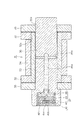
本発明の実施例を図1〜図3に基づいて説明する。図1は潤滑油自動給油型チェーンの要部を示す概略断面図、図2は潤滑油ボンベを装着する前のピンの断面図、図3は潤滑油ボンベの断面図である。 An embodiment of the present invention will be described with reference to FIGS. FIG. 1 is a schematic cross-sectional view showing a main part of a lubricating oil automatic supply chain, FIG. 2 is a cross-sectional view of a pin before mounting a lubricating oil cylinder, and FIG. 3 is a sectional view of the lubricating oil cylinder.
図1に示すように、潤滑油自動給油型チェーン1は、一対の内プレート2,2と一対の外プレート5,5とが、ブシュ3が外嵌されたピン6で連結されて構成される。すなわち、潤滑油自動給油型チェーン1は、一対の内プレート2にそれぞれ穿設された一対のブシュ孔2a,2aにブシュ3,3の両端が嵌着固定され、このブシュ3にはローラ4が適宜に回転自在に外嵌され、また、一対の外プレート5,5にそれぞれ穿設されたピン孔5a,5aにピン6,6の両端が嵌着固定され、このピン6,6は前記ブシュ3,3内に回転自在に嵌挿されて構成される。
As shown in FIG. 1, the lubricating oil automatic oil supply type chain 1 is configured by connecting a pair of inner plates 2 and 2 and a pair of
図2に示すように、ピン6の長手方向略々中央部にピン内部からピン外周面6aに開口する給油孔7が形成され、給油孔7からピン外周面6aに潤滑油Mを供給可能となっている。また、ピン6の内部には、ピン6の一方側端部が開口しピン長手方向略々中央に底部8を有する中空部9がピン長手方向に亘って形成されると共に、この底部8に前記給油孔7に連通する潤滑油流入口10aを有する凹嵌部10が形成されている。
As shown in FIG. 2, an
前記中空部9には、中空部長さに略々匹敵する長さの潤滑油ボンベ11が着脱可能に装着される。潤滑油ボンベ11の先端には潤滑油流出口12aを有する突出部12が形成され、潤滑油ボンベ11が中空部9に装着されたとき、突出部12が凹嵌部10に密着嵌合し、突出部12の潤滑油流出口12aと凹嵌部10の潤滑油流入口10aとが接続され、後記する潤滑油貯留室15と給油孔7とが連通する。この場合、潤滑油流出口12a、又は突出部12が嵌合する近傍の給油孔17に逆流防止弁を取り付けるようにしても構わない。なお、図2あるいは図3における符号10b、12bはそれぞれねじ部である。
A lubricating
前記潤滑油ボンベ11は、摺動自在なピストン13で仕切られたガス充填室14と、潤滑油貯留室15とを備えると共に、後端部に該ガス充填室14にガスを徐放する徐放機能付のガス発生器16を備えている。
The lubricating
ガス発生器16はガス流出口16aを備え、ガス発生器16には、一般に市販されている乾電池式のガスジェネレータ17が設けられる。このガスジェネレータ17は、ガス発生物質18及び乾電池19で構成される。乾電池19の陰極側、陽極側にはそれぞれコード20a,20bが接続され、コード20aは、ピストン13に取り付けられた接点13aに接続され、コード20bは、パイロットランプ21介在させて潤滑油ボンベ11の先端に取り付けられた接点11aに接続される。上記のガス発生物質は、例えばマグネシウム、リチウム等を含む水素吸蔵合金などの物質で発熱により水素を発生させるものである。
The
ガスジェネレータ17で徐々に発生した水素ガスをガス流出口16aからガス充填室14に供給し、ガス充填室14に蓄積されたガスのガス圧によりピストン13を移動させることにより、潤滑油貯留室15内の潤滑油Mを給油孔7からピン外周面6aに供給する。この場合、ピストン13が移動して潤滑油貯留室15内の潤滑油Mが押し出され枯渇すると、ピストン13に取り付けられた接点13aと潤滑油ボンベ11の先端に取り付けられた接点11aとが接触し、パイロットランプ21が点灯する。
Hydrogen gas gradually generated by the
上記構成からなる本発明の潤滑油自動給油型チェーンは、以下のような格別の効果を奏する。潤滑油自動給油型チェーン1を構成するピン6の内部には、ピン6の一方側端部が開口しピン長手方向略々中央に底部8を有する中空部9がピン長手方向に亘って形成されているので、ピンの中空部9に装着する潤滑油ボンベ11の長さを中空部長さに略々匹敵する長さにすることができ、その結果、潤滑油貯留室15が大きくなるため潤滑油ボンベ内にかなりの量の潤滑油Mを貯留することができ、頻繁な潤滑油補給を回避することができる。
The lubricating oil automatic oil supply type chain of the present invention having the above-described configuration has the following special effects. Inside the
また、中空部9の底部8にピン内部の給油孔7に連通する潤滑油流入口10aを有する凹嵌部10が形成され、中空部9には潤滑油ボンベ11が着脱可能に装着され、潤滑油ボンベ11の先端には、潤滑油流出口12aを有する突出部12が形成され、ねじ部10b、12bを介して突出部12が凹嵌部10に密着嵌合されているので、潤滑油ボンベ11をカートリッジタイプのものとすることができ、潤滑油ボンベ11の交換のみで潤滑油Mの補給ができ、補給メンテナンスの向上を図ることができる。
Further, a concave
潤滑油ボンベ11は、摺動自在なピストン13で仕切られたガス充填室14と、潤滑油貯留室15とを備えると共に、後端部にガス充填室14にガスを徐放する徐放機能付のガス発生器16を備え、ガス発生器16には、乾電池式のガスジェネレータ17が設けられ、ガスジェネレータ17より徐々に発生したガスをガス充填室14に供給し、ガス充填室14に蓄積されたガスのガス圧によりピストン13を移動させるので、ガス発生器16から徐放されるガス圧のピストン13移動により、潤滑油ボンベ11内の潤滑油Mが枯渇するまで潤滑油Mを一定の圧力でピン外周面6aの摺動部に供給することができる。また、潤滑油自動給油型チェーン1は、潤滑油Mをピン外周面6aに安定して供給できるため、潤滑油消費量の多いバケットチェーンや自動車などの重量物を昇降搬送するための大荷重用チェーンとして好適に用いることができる。
The lubricating
潤滑油ボンベ11には、潤滑油貯留室15の潤滑油Mが枯渇したことを表示する表示機構が備えられ、この表示機構は、ピストン13と連動可能に設けられた接点13aと、潤滑油ボンベ11の先端に設けられた接点11aとの接触通電により、パイロットランプ21が点灯される機構であることにより、チェーン走行中においても潤滑油ボンベ11内の潤滑油Mが枯渇したことを速やかに判別することができる。
The lubricating
1 潤滑油自動給油型チェーン 2 内プレート
2a ブシュ孔 3 ブシュ
4 ローラ 5 外プレート
5a ピン孔 6 ピン
6a ピン外周面 7 給油孔
8 底部 9 中空部
10 凹嵌部 10a 潤滑油流入口
10b ねじ部 11 潤滑油ボンベ
11a 接点 12 突出部
12a 潤滑油流出口 12b ねじ部
13 ピストン 13a 接点
14 ガス充填室 15 潤滑油貯留室
16 ガス発生器 16a ガス流出口
17 ガスジェネレータ 18 ガス発生物質
19 乾電池 20a,20b コード
21 パイロットランプ M 潤滑油
DESCRIPTION OF SYMBOLS 1 Lubricant automatic oil supply type chain 2 Inner plate 2a Bushing hole 3 Bushing 4
Claims (1)
前記ピン内部には、ピンの一方側端部が開口しピン長手方向略々中央に底部を有する中空部がピン長手方向に亘って形成されると共に、該底部に前記給油孔に連通する潤滑油流入口を有する凹嵌部が形成され、
前記中空部には、該中空部長さに略々匹敵する長さの潤滑油ボンベが着脱可能に装着され、
前記潤滑油ボンベの先端には、潤滑油流出口を有する突出部が形成され、該突出部が前記凹嵌部に密着嵌合され、
前記潤滑油ボンベは、摺動自在なピストンで仕切られたガス充填室と、潤滑油貯留室とを備えると共に、後端部に該ガス充填室にガスを徐放するガス発生器を備え、
前記ガス発生器には、乾電池式のガスジェネレータが設けられ、該ガスジェネレータより徐々に発生したガスを前記ガス充填室に供給し、該ガス充填室に蓄積されたガスのガス圧により前記ピストンを移動させ、
前記潤滑油ボンベには、前記潤滑油貯留室の潤滑油が枯渇したことを表示する表示機構が備えられ、
前記表示機構は、前記ピストンと連動可能に設けられて前記ガスジェネレータの乾電池に接続された接点と、前記潤滑油ボンベの先端に設けられて前記乾電池に接続された接点との接触通電により、前記潤滑油ボンベに設けられたパイロットランプが点灯される機構であることを特徴とする潤滑油自動給油型チェーン。 The inner plate and the outer plate are connected by a pin on which a bush and / or a roller are fitted, and an oil supply hole that opens from the inside of the pin to the outer peripheral surface of the pin is formed at a substantially central portion in the longitudinal direction of the pin. In the lubricating oil automatic lubrication type chain that can supply lubricating oil from the hole to the pin outer peripheral surface,
Inside the pin, a hollow portion having an opening at one end of the pin and having a bottom portion approximately in the center in the longitudinal direction of the pin is formed over the longitudinal direction of the pin, and the lubricating oil communicating with the oil supply hole at the bottom portion A recessed fitting portion having an inflow port is formed,
The hollow part is detachably mounted with a lubricating oil cylinder having a length approximately equal to the length of the hollow part,
At the tip of the lubricating oil cylinder, a protruding portion having a lubricating oil outlet is formed, and the protruding portion is closely fitted to the recessed fitting portion,
The lubricating oil cylinder includes a gas filling chamber partitioned by a slidable piston, a lubricating oil storage chamber, and a gas generator that gradually releases gas into the gas filling chamber at a rear end portion.
The gas generator is provided with a dry cell type gas generator, and gas generated gradually from the gas generator is supplied to the gas filling chamber, and the piston is driven by the gas pressure of the gas accumulated in the gas filling chamber. Move
The lubricating oil cylinder is provided with a display mechanism for displaying that the lubricating oil in the lubricating oil reservoir is depleted,
The display mechanism is connected to the piston connected to the dry battery of the gas generator, and the contact mechanism is connected to the dry battery connected to the dry battery and connected to the dry battery. An automatic lubricating oil supply chain characterized in that a pilot lamp provided in a lubricating oil cylinder is turned on.
Priority Applications (1)
| Application Number | Priority Date | Filing Date | Title |
|---|---|---|---|
| JP2006073030A JP4948005B2 (en) | 2006-03-16 | 2006-03-16 | Lubricant automatic lubrication type chain |
Applications Claiming Priority (1)
| Application Number | Priority Date | Filing Date | Title |
|---|---|---|---|
| JP2006073030A JP4948005B2 (en) | 2006-03-16 | 2006-03-16 | Lubricant automatic lubrication type chain |
Publications (2)
| Publication Number | Publication Date |
|---|---|
| JP2007246234A JP2007246234A (en) | 2007-09-27 |
| JP4948005B2 true JP4948005B2 (en) | 2012-06-06 |
Family
ID=38590926
Family Applications (1)
| Application Number | Title | Priority Date | Filing Date |
|---|---|---|---|
| JP2006073030A Active JP4948005B2 (en) | 2006-03-16 | 2006-03-16 | Lubricant automatic lubrication type chain |
Country Status (1)
| Country | Link |
|---|---|
| JP (1) | JP4948005B2 (en) |
Cited By (2)
| Publication number | Priority date | Publication date | Assignee | Title |
|---|---|---|---|---|
| CN104454885A (en) * | 2014-12-10 | 2015-03-25 | 苏州市顺仪五金有限公司 | Automatic oil outlet and return bolt |
| CN104454891A (en) * | 2014-12-10 | 2015-03-25 | 苏州市顺仪五金有限公司 | Automatic oil outlet bolt |
Families Citing this family (2)
| Publication number | Priority date | Publication date | Assignee | Title |
|---|---|---|---|---|
| JP4700092B2 (en) * | 2008-10-01 | 2011-06-15 | 株式会社椿本チエイン | Automatic oiling chain |
| CN113879800B (en) * | 2021-09-10 | 2023-05-09 | 绩溪徽腾机械有限公司 | Chain pin shaft with high static load bending strength |
Family Cites Families (5)
| Publication number | Priority date | Publication date | Assignee | Title |
|---|---|---|---|---|
| JPS6272998A (en) * | 1985-09-24 | 1987-04-03 | Hitachi Seiki Co Ltd | Lubricating oil monitor device |
| JPS62163729U (en) * | 1986-04-08 | 1987-10-17 | ||
| JPH0437652U (en) * | 1990-07-24 | 1992-03-30 | ||
| JPH07277479A (en) * | 1994-04-01 | 1995-10-24 | Riyuube Kk | Automatic continuous lubrication device for conveyor chain |
| JP4180164B2 (en) * | 1998-11-05 | 2008-11-12 | 株式会社椿本チエイン | Chain with automatic lubricator |
-
2006
- 2006-03-16 JP JP2006073030A patent/JP4948005B2/en active Active
Cited By (2)
| Publication number | Priority date | Publication date | Assignee | Title |
|---|---|---|---|---|
| CN104454885A (en) * | 2014-12-10 | 2015-03-25 | 苏州市顺仪五金有限公司 | Automatic oil outlet and return bolt |
| CN104454891A (en) * | 2014-12-10 | 2015-03-25 | 苏州市顺仪五金有限公司 | Automatic oil outlet bolt |
Also Published As
| Publication number | Publication date |
|---|---|
| JP2007246234A (en) | 2007-09-27 |
Similar Documents
| Publication | Publication Date | Title |
|---|---|---|
| JP4948005B2 (en) | Lubricant automatic lubrication type chain | |
| JP4700092B2 (en) | Automatic oiling chain | |
| JP4931820B2 (en) | Seal chain with greasing device | |
| BRPI0601341A (en) | piston type compressor | |
| JP4180164B2 (en) | Chain with automatic lubricator | |
| JP2012233538A (en) | Grease injection device and crawler belt tensile force adjustment device using the same | |
| CN212028337U (en) | Oil-supplementing type retainer | |
| JP5285341B2 (en) | Tensioning device | |
| CN106715927B (en) | Hydraulic cylinder | |
| KR102173573B1 (en) | Pressurized drive for automatic oil injector | |
| KR100809112B1 (en) | Ball joint | |
| JP2007278203A (en) | Valve | |
| CN208982500U (en) | A kind of self-lubricating oily bearing | |
| CN212155470U (en) | Novel wear-resisting bearing bush | |
| KR20070001043U (en) | Balljoint | |
| KR101467536B1 (en) | roller for combustion gate | |
| CN215158239U (en) | Scraper device of anti-return slag conveyor | |
| PT2321215E (en) | Attachment for forklift trucks or shovel loaders | |
| CN217808482U (en) | Hydraulic capstan with good lubricating property | |
| CN220500848U (en) | Guiding wheel with self-lubricating function | |
| CN216129965U (en) | Spherical support capable of supplementing silicone grease | |
| CN219866207U (en) | Wear-resisting planetary gasket | |
| CN218720513U (en) | Lubricating grease compensation mechanism applied to rack and pinion steering gear | |
| CN202301695U (en) | Wear-resistant self lubrication nitrogen gas spring | |
| CN111775645A (en) | Sliding plate seat with lubricating grease groove |
Legal Events
| Date | Code | Title | Description |
|---|---|---|---|
| A621 | Written request for application examination |
Free format text: JAPANESE INTERMEDIATE CODE: A621 Effective date: 20080311 |
|
| A977 | Report on retrieval |
Free format text: JAPANESE INTERMEDIATE CODE: A971007 Effective date: 20110210 |
|
| A131 | Notification of reasons for refusal |
Free format text: JAPANESE INTERMEDIATE CODE: A131 Effective date: 20110607 |
|
| A521 | Written amendment |
Free format text: JAPANESE INTERMEDIATE CODE: A523 Effective date: 20110726 |
|
| TRDD | Decision of grant or rejection written | ||
| A01 | Written decision to grant a patent or to grant a registration (utility model) |
Free format text: JAPANESE INTERMEDIATE CODE: A01 Effective date: 20120306 |
|
| A01 | Written decision to grant a patent or to grant a registration (utility model) |
Free format text: JAPANESE INTERMEDIATE CODE: A01 |
|
| A61 | First payment of annual fees (during grant procedure) |
Free format text: JAPANESE INTERMEDIATE CODE: A61 Effective date: 20120306 |
|
| FPAY | Renewal fee payment (event date is renewal date of database) |
Free format text: PAYMENT UNTIL: 20150316 Year of fee payment: 3 |
|
| R150 | Certificate of patent or registration of utility model |
Ref document number: 4948005 Country of ref document: JP Free format text: JAPANESE INTERMEDIATE CODE: R150 Free format text: JAPANESE INTERMEDIATE CODE: R150 |