JP4947094B2 - Projector and optical apparatus - Google Patents
Projector and optical apparatus Download PDFInfo
- Publication number
- JP4947094B2 JP4947094B2 JP2009138939A JP2009138939A JP4947094B2 JP 4947094 B2 JP4947094 B2 JP 4947094B2 JP 2009138939 A JP2009138939 A JP 2009138939A JP 2009138939 A JP2009138939 A JP 2009138939A JP 4947094 B2 JP4947094 B2 JP 4947094B2
- Authority
- JP
- Japan
- Prior art keywords
- light
- color
- light source
- source unit
- unit
- Prior art date
- Legal status (The legal status is an assumption and is not a legal conclusion. Google has not performed a legal analysis and makes no representation as to the accuracy of the status listed.)
- Expired - Fee Related
Links
Images


Description
本発明は、プロジェクタ及び光学装置、特に、光源部として固体発光素子を用いるプロジェクタに関するものである。 The present invention relates to a projector and an optical device, and more particularly to a projector using a solid light emitting element as a light source unit.
プロジェクタは、コンピュータ等からの画像供給装置から供給される画像信号に応じて光(投写光)を投写し、画像を表示する装置である。プロジェクタは、表示デバイスの入出力特性、信号処理回路等の電気的特性、光学系の光学特性等により、投写像に色むらを生じることが知られている。画像表示装置等において生じる色むらを解消する技術は、以下に示す特許文献1にて提案されている。
The projector is a device that projects light (projection light) in accordance with an image signal supplied from an image supply device from a computer or the like and displays an image. It is known that a projector causes color unevenness in a projected image due to input / output characteristics of a display device, electrical characteristics of a signal processing circuit, optical characteristics of an optical system, and the like. A technique for eliminating color unevenness that occurs in an image display device or the like is proposed in
近年、プロジェクタの光源部に発光ダイオード素子、半導体レーザ等の固体発光素子を使用することが考えられている。固体発光素子は、小型かつ軽量であり、近年の開発により発光輝度が著しく向上していることから、プロジェクタの光源部に適している。固体発光素子を光源部とする場合、例えば、第1色光である赤色光(以下、「R光」という。)を供給する第1光源部と、第2色光である緑色光(以下、「G光」という。)を供給する第2光源部と、第3色光である青色光(以下、「B光」という。)を供給する第3光源部とを有する構成とすることができる。第1光源部、第2光源部及び第3光源部を有する構成とすることにより、光源部の配置の自由度が増し、簡易な構成とすることができるという利点がある。 In recent years, it has been considered to use a solid-state light-emitting element such as a light-emitting diode element or a semiconductor laser in a light source section of a projector. The solid light-emitting element is small and lightweight, and its light emission luminance has been remarkably improved by recent developments. Therefore, it is suitable for a light source part of a projector. When the solid-state light emitting element is used as a light source unit, for example, a first light source unit that supplies red light (hereinafter referred to as “R light”) that is first color light, and green light (hereinafter referred to as “G light” that is second color light). The light source may be a second light source unit that supplies light, and a third light source unit that supplies blue light (hereinafter referred to as “B light”) that is third color light. The configuration having the first light source unit, the second light source unit, and the third light source unit has an advantage that the degree of freedom of arrangement of the light source unit is increased and a simple configuration can be obtained.
第1光源部、第2光源部及び第3光源部と、波長領域の異なる複数の光源部を用いる構成は上述の利点を有するにも関わらず、いずれかの光源部に明るさむら、即ち輝度の不均一性が発生した場合、投写像に色むらが発生してしまう。例えば、R光を供給する光源部に輝度の不均一性、いわゆる明るさむらが発生し、スクリーンの投写像のほぼ中央にR光が他の領域に比較して強い部分が生じているとする。この場合、投写像のほぼ中央部分の領域はG光、B光よりR光が強調され、色むらのある投写像となる。複数の光源部間の輝度のばらつきを軽減する場合、各光源部の駆動電流、電圧等の電気的状態を一定にする方法がとられる。しかし、単独の光源部に発生する輝度の不均一性は、光源部の電気的状態を一定にしても発生してしまう。 Although the configuration using the first light source unit, the second light source unit, and the third light source unit and the plurality of light source units having different wavelength regions has the above-described advantages, brightness unevenness in any one of the light source units, that is, luminance If non-uniformity occurs, color unevenness occurs in the projected image. For example, it is assumed that non-uniform luminance, that is, so-called brightness unevenness occurs in a light source unit that supplies R light, and a portion where the R light is stronger than other regions is generated at the approximate center of the projected image on the screen. . In this case, the R light is emphasized from the G light and the B light in the region at the substantially central portion of the projected image, and a projected image with uneven color is obtained. In order to reduce variations in luminance among a plurality of light source units, a method is adopted in which the electrical state such as drive current and voltage of each light source unit is made constant. However, luminance non-uniformity generated in a single light source unit occurs even if the electrical state of the light source unit is constant.
光源部の輝度分布の不均一性は、温度変化に伴い変化する。このため、波長領域の異なる複数の光源部を用いる場合は、温度変化に伴い各光源部からの各色光それぞれの色むら分布が変化する。例えば、表示画像のほぼ中央にR光の強調される部分が生じている場合に、R光を供給する光源部の温度が上昇したとする。この場合、例えば、R光の強調される領域がひとまわり広がる等の変化が起こる。 The non-uniformity of the luminance distribution of the light source unit changes with a temperature change. For this reason, when using a plurality of light source units having different wavelength regions, the color unevenness distribution of each color light from each light source unit changes with a temperature change. For example, it is assumed that the temperature of the light source unit that supplies the R light rises when a portion where the R light is emphasized is generated at substantially the center of the display image. In this case, for example, a change occurs such that the region where the R light is emphasized spreads around.
従来の色むら解消技術では、光源部の温度変化に伴うこのような色むらの変化に対応して、色むらを解消することは困難であり問題である。本発明は、上述の問題を解決するためになされたものであり、光源部の温度変化に起因する色むらを低減でき、良好なフルカラー像のプロジェクタ及び光学装置を提供することを目的とする。 In the conventional color unevenness elimination technology, it is difficult and problematic to eliminate the color unevenness in response to such a color unevenness change accompanying the temperature change of the light source unit. SUMMARY An advantage of some aspects of the invention is that it provides a projector and an optical apparatus that can reduce uneven color due to a temperature change of a light source unit and can provide a satisfactory full color image.
上記課題を解決し、目的を達成するために、本発明では、第1色光を供給する第1光源部と、第2色光を供給する第2光源部と、第3色光を供給する第3光源部と、前記第1光源部の近傍に配置され、前記第1光源部の温度を検出する第1温度検出部と、前記第2光源部の近傍に配置され、前記第2光源部の温度を検出する第2温度検出部と、前記第3光源部の近傍に配置され、前記第3光源部の温度を検出する第3温度検出部と、前記第1光源部、前記第2光源部及び前記第3光源部からの光を画像信号に応じて変調する空間光変調装置と、前記空間光変調装置で変調された光をスクリーンに投写する投写レンズと、前記第1光源部の温度と前記第1光源部からの前記第1色光の輝度分布との関係と、前記第2光源部の温度と前記第2光源部からの前記第2色光の輝度分布との関係と、前記第3光源部の温度と前記第3光源部からの前記第3色光の輝度分布との関係とを記憶する記憶部と、前記第1温度検出部、前記第2温度検出部、及び前記第3温度検出部によりそれぞれ検出された前記第1光源部、前記第2光源部、及び前記第3光源部の温度と、前記記憶部に記憶されている前記第1色光、前記第2色光、及び前記第3色光の輝度分布との関係に基づいて、前記スクリーンにおいて前記第1色光、前記第2色光、及び前記第3色光のそれぞれの輝度分布が略均一となるように前記空間光変調装置を制御する制御部と、を有することを特徴とするプロジェクタを提供できる。 In order to solve the above problems and achieve the object, in the present invention, a first light source unit that supplies first color light, a second light source unit that supplies second color light, and a third light source that supplies third color light are provided. And a first temperature detection unit that is disposed in the vicinity of the first light source unit, detects the temperature of the first light source unit, and is disposed in the vicinity of the second light source unit, and controls the temperature of the second light source unit. A second temperature detection unit for detecting, a third temperature detection unit arranged in the vicinity of the third light source unit for detecting the temperature of the third light source unit, the first light source unit, the second light source unit, and the A spatial light modulator that modulates light from the third light source unit according to an image signal, a projection lens that projects the light modulated by the spatial light modulator on a screen, the temperature of the first light source unit, and the first light source unit The relationship between the luminance distribution of the first color light from one light source unit, the temperature of the second light source unit, and the second light source A storage unit for storing a relationship between the luminance distribution of the second color light from the first light source and a relationship between the temperature of the third light source unit and the luminance distribution of the third color light from the third light source unit; Temperatures of the first light source unit, the second light source unit, and the third light source unit detected by the temperature detection unit, the second temperature detection unit, and the third temperature detection unit, respectively, are stored in the storage unit. Based on the relationship between the luminance distribution of the first color light, the second color light, and the third color light, the respective luminances of the first color light, the second color light, and the third color light on the screen And a control unit that controls the spatial light modulator so that the distribution is substantially uniform.
各温度検出部で検出された温度と輝度分布との関係に基づいて、各色光の輝度分布が略均一となるように空間光変調装置を制御することにより、各光源部の温度変化に伴う色むらを低減することができる。また、記憶部に記憶された各光源部の温度と各色光の輝度分布との関係に基づいて空間光変調装置を制御することにより、各色光の輝度を一定に保ち、色むらの低減された投写像のプロジェクタを得られる。 By controlling the spatial light modulator so that the luminance distribution of each color light becomes substantially uniform based on the relationship between the temperature detected by each temperature detection unit and the luminance distribution, the color associated with the temperature change of each light source unit Unevenness can be reduced. In addition, by controlling the spatial light modulator based on the relationship between the temperature of each light source unit stored in the storage unit and the luminance distribution of each color light, the luminance of each color light is kept constant, and the color unevenness is reduced. A projector with a projected image can be obtained.
また、本発明の好ましい態様としては、前記記憶部は、さらに、投写像の階調を補正するための階調補正値を記憶し、前記制御部は、前記第1温度検出部、前記第2温度検出部、及び前記第3温度検出部によりそれぞれ検出された前記第1光源部、前記第2光源部、及び前記第3光源部の温度に基づいて、前記階調補正値を変更して使用することにより、前記スクリーンにおいて前記第1色光、前記第2色光、及び前記第3色光のそれぞれの輝度分布が略均一となるように前記空間光変調装置を制御することが望ましい。 In a preferred aspect of the present invention, the storage unit further stores a gradation correction value for correcting the gradation of the projected image, and the control unit includes the first temperature detection unit and the second temperature detection unit. The gradation correction value is changed and used based on the temperatures of the first light source unit, the second light source unit, and the third light source unit detected by the temperature detection unit and the third temperature detection unit, respectively. By doing so, it is desirable to control the spatial light modulation device so that the luminance distributions of the first color light, the second color light, and the third color light are substantially uniform on the screen.
空間光変調装置は、各光源部の温度に基づいて階調補正値を変更して使用することにより、各色光の輝度分布が略均一となるように制御される。階調補正値とは、所望の自然な色の画像を正確に再現するために、各色光の明るさのレベルを変換する数値である。階調補正とともに、各光源部の温度変化に伴う色むらを低減することにより、色むらが少なく、かつカラーバランスが良好なプロジェクタを得られる。 The spatial light modulator is controlled so that the luminance distribution of each color light becomes substantially uniform by changing the gradation correction value based on the temperature of each light source unit. The gradation correction value is a numerical value for converting the brightness level of each color light in order to accurately reproduce a desired natural color image. By reducing the color unevenness associated with the temperature change of each light source unit together with the gradation correction, a projector with less color unevenness and good color balance can be obtained.
また、本発明の好ましい態様としては、前記記憶部は、さらに、前記第1光源部の温度変化量と、前記第1光源部からの前記第1色光の波長領域のシフト量と、ホワイトバランスの調整を行うための前記第1色光、前記第2色光並びに前記第3色光の光量シフト量との関係と、前記第2光源部の温度変化量と、前記第2光源部からの前記第2色光の波長領域のシフト量と、ホワイトバランスの調整を行うための前記第1色光、前記第2色光並びに前記第3色光の光量シフト量との関係と、前記第3光源部の温度変化量と、前記第3光源部からの前記第3色光の波長領域のシフト量と、ホワイトバランスの調整を行うための前記第1色光、前記第2色光並びに前記第3色光の光量シフト量との関係とを記憶し、前記制御部は、さらに、前記第1温度検出部、前記第2温度検出部、及び前記第3温度検出部によりそれぞれ検出された前記第1光源部、前記第2光源部、及び前記第3光源部の温度変化量と、前記記憶部に記憶されている前記第1色光、前記第2色光及び前記第3色光の光量シフト量との関係に基づいて、ホワイトバランスの調整を行うために前記第1光源部、前記第2光源部、及び前記第3光源部の光量を制御することが望ましい。 In a preferred aspect of the present invention, the storage unit further includes a temperature change amount of the first light source unit, a shift amount of the wavelength region of the first color light from the first light source unit, and a white balance. The relationship between the light amount shift amount of the first color light, the second color light, and the third color light for adjustment, the temperature change amount of the second light source unit, and the second color light from the second light source unit The relationship between the shift amount of the wavelength region, the light amount shift amount of the first color light, the second color light, and the third color light for adjusting the white balance, and the temperature change amount of the third light source unit, The relationship between the shift amount of the wavelength region of the third color light from the third light source unit and the light amount shift amount of the first color light, the second color light, and the third color light for adjusting white balance. And the control unit further stores the first A temperature change amount of the first light source unit, the second light source unit, and the third light source unit respectively detected by the degree detection unit, the second temperature detection unit, and the third temperature detection unit, and the storage unit The first light source unit, the second light source unit, and the second light source unit for adjusting white balance based on the relationship between the light amount shift amounts of the first color light, the second color light, and the third color light stored in It is desirable to control the light amount of the third light source unit.
各温度検出部で検出された温度変化量と、ホワイトバランスの調整を行うための各色光の光量シフト量との関係に基づいて、各光源部からの各色光の光量を制御することにより、自然な色の画像を正確に再現することができる。また、記憶部に記憶された各光源部の温度変化量と各色光の光量シフト量との関係に基づいて各色光の光量を制御することにより、ホワイトバランスを一定に保ち、自然な色の画像を正確に再現することができる。 By controlling the light quantity of each color light from each light source part based on the relationship between the amount of temperature change detected by each temperature detection part and the light quantity shift amount of each color light for white balance adjustment, Accurate color images can be accurately reproduced. In addition, by controlling the light amount of each color light based on the relationship between the temperature change amount of each light source unit stored in the storage unit and the light amount shift amount of each color light, the white balance is kept constant, and the natural color image Can be accurately reproduced.
また、本発明の好ましい態様としては、前記第1色光、前記第2色光、及び前記第3色光のそれぞれの輝度分布を検出するための光検出部をさらに有し、前記制御部は、前記光検出部により検出された前記第1色光、前記第2色光、及び前記第3色光のそれぞれの輝度分布に基づいて、前記第1色光、前記第2色光、及び前記第3色光のそれぞれの輝度分布が略均一となるように前記空間光変調装置を制御することが望ましい。光検出部は、各色光の輝度分布を検出する。制御部は、各色光の輝度分布に応じて、各色光のそれぞれの輝度分布が略均一となるように空間光変調装置を制御する。これにより、各色光の輝度(明るさ)を一定に保ち、色むらの低減された投写像のプロジェクタを得られる。 Moreover, as a preferable aspect of the present invention, it further includes a light detection unit for detecting a luminance distribution of each of the first color light, the second color light, and the third color light, and the control unit includes the light Based on the respective luminance distributions of the first color light, the second color light, and the third color light detected by the detection unit, the respective luminance distributions of the first color light, the second color light, and the third color light. It is desirable to control the spatial light modulator so that is substantially uniform. The light detection unit detects the luminance distribution of each color light. The control unit controls the spatial light modulation device according to the luminance distribution of each color light so that the luminance distribution of each color light becomes substantially uniform. As a result, it is possible to obtain a projection image projector in which the luminance (brightness) of each color light is kept constant and the color unevenness is reduced.
また、本発明の好ましい態様としては、前記投写レンズから前記スクリーンに投写された前記第1色光、前記第2色光、及び前記第3色光を、それぞれ前記光検出部に導く検出光学系をさらに有することが望ましい。検出光学系を設け、投写レンズからスクリーンに投写された各色光を光検出部に導く構成とすることにより、光検出部で各色光のスクリーン上での輝度分布を検出することができる。これにより、各色光の輝度(明るさ)を一定に保ち、色むらの低減された投写像のプロジェクタを得られる。 In a preferred aspect of the present invention, the optical system further includes a detection optical system that guides the first color light, the second color light, and the third color light projected from the projection lens onto the screen, respectively, to the light detection unit. It is desirable. By providing a detection optical system and guiding each color light projected on the screen from the projection lens to the light detection unit, the light detection unit can detect the luminance distribution on the screen of each color light. As a result, it is possible to obtain a projection image projector in which the luminance (brightness) of each color light is kept constant and the color unevenness is reduced.
また、本発明の好ましい態様としては、前記空間光変調装置と前記投写レンズとの間の光路中に設けられ、前記空間光変調装置で変調された前記第1色光、前記第2色光及び前記第3色光をそれぞれ投写レンズの方向と前記光検出部の方向とに分岐する光分岐部をさらに有し、前記光検出部は、前記光分岐部により分岐される光を検出することが望ましい。 In a preferred aspect of the present invention, the first color light, the second color light, and the first color light that are provided in an optical path between the spatial light modulation device and the projection lens and are modulated by the spatial light modulation device. It is desirable to further include a light branching unit that branches three-color light into the direction of the projection lens and the direction of the light detection unit, and the light detection unit detects light branched by the light branching unit.
空間光変調装置と投写レンズとの間の光路中に光分岐部を設け、光分岐部により分岐される光を光検出部に導く構成とすることにより、光検出部で各色光の輝度分布を検出することができる。これにより、各色光の輝度(明るさ)を一定に保ち、色むらの低減された投写像のプロジェクタを得られる。 By providing a light branching unit in the optical path between the spatial light modulation device and the projection lens and guiding the light branched by the light branching unit to the light detection unit, the light detection unit can control the luminance distribution of each color light. Can be detected. As a result, it is possible to obtain a projection image projector in which the luminance (brightness) of each color light is kept constant and the color unevenness is reduced.
また、本発明の好ましい態様としては、前記光検出部は、前記第1色光を検出する第1色光用光検出部と、前記第2色光を検出する第2色光用光検出部と、前記第3色光を検出する第3色光用光検出部とからなり、前記第1光源部と前記空間光変調装置との間の光路中に設けられ、前記第1光源部からの前記第1色光を前記空間光変調装置の方向と前記第1色光用光検出部の方向とに分岐する第1色光用光分岐部と、前記第2光源部と前記空間光変調装置との間の光路中に設けられ、前記第2光源部からの前記第2色光を前記空間光変調装置の方向と前記第2色光用光検出部の方向とに分岐する第2色光用光分岐部と、前記第3光源部と前記空間光変調装置との間の光路中に設けられ、前記第3光源部からの前記第3色光を前記空間光変調装置の方向と前記第3色光用光検出部の方向とに分岐する第3色光用光分岐部と、を有することが望ましい。 In a preferred aspect of the present invention, the light detection unit includes a first color light detection unit that detects the first color light, a second color light detection unit that detects the second color light, and the first color light detection unit. A third color light detection unit for detecting three-color light, provided in an optical path between the first light source unit and the spatial light modulator, and the first color light from the first light source unit Provided in the optical path between the second light source unit and the spatial light modulator, the first color light beam splitter branching in the direction of the spatial light modulator and the first color light detector. A second color light branching unit that branches the second color light from the second light source unit into a direction of the spatial light modulator and a direction of the second color light detection unit, and the third light source unit. The third color light from the third light source unit is provided in an optical path between the spatial light modulator and the spatial light modulator. A third color Hikari Mitsumochi branching section that branches to the direction of direction as the third color Hikari Mitsumochi unit, it is desirable to have.
光源部と空間光変調装置との間の光路中に光分岐部を設け、光分岐部により分岐される光を光検出部に導く構成とすることにより、光検出部で各色光の輝度分布を検出することができる。これにより、各色光の輝度(明るさ)を一定に保ち、色むらの低減された投写像のプロジェクタを得られる。 By providing a light branching unit in the optical path between the light source unit and the spatial light modulator and guiding the light branched by the light branching unit to the light detection unit, the light detection unit can control the luminance distribution of each color light. Can be detected. As a result, it is possible to obtain a projection image projector in which the luminance (brightness) of each color light is kept constant and the color unevenness is reduced.
また、本発明の好ましい態様としては、さらに、前記空間光変調装置は、前記第1光源部からの前記第1色光と、前記第2光源部からの前記第2色光と、前記第3光源部からの前記第3色光とのそれぞれを前記投写レンズの方向又は前記投写レンズ以外の方向に反射させる可動ミラー素子からなるティルトミラーデバイスであって、前記光検出部は、前記空間光変調装置により前記投写レンズ以外の方向に反射される光を検出することが望ましい。 Moreover, as a preferable aspect of the present invention, the spatial light modulator further includes the first color light from the first light source unit, the second color light from the second light source unit, and the third light source unit. The tilt mirror device is composed of a movable mirror element that reflects each of the third color light from the projection lens in the direction of the projection lens or the direction other than the projection lens, and the light detection unit is It is desirable to detect light reflected in a direction other than the projection lens.
ティルトミラーデバイスから投写レンズ以外の方向に反射される光を光検出部に導く構成とすることにより、光検出部で各色光の輝度分布を検出することができる。また、画像投写中に光検出部の方向に反射される光は、投写像の形成に不要となる成分の光である。従って、投写像を形成する光を減少させることがないので、投写光の光路中において光を分岐する構成よりもさらに明るい投写像を得られる。これにより、明るく、色むらの低減された投写像のプロジェクタを得られる。 By adopting a configuration that guides light reflected from the tilt mirror device in a direction other than the projection lens to the light detection unit, the light detection unit can detect the luminance distribution of each color light. Further, the light reflected in the direction of the light detection unit during image projection is light of a component that is unnecessary for forming a projected image. Accordingly, since the light forming the projection image is not reduced, a brighter projection image can be obtained than the configuration in which light is branched in the optical path of the projection light. As a result, it is possible to obtain a projector having a bright projection image with reduced color unevenness.
さらに、本発明では、第1色光を供給する第1光源部と、第2色光を供給する第2光源部と、第3色光を供給する第3光源部と、前記第1光源部の近傍に配置され、前記第1光源部の温度を検出する第1温度検出部と、前記第2光源部の近傍に配置され、前記第2光源部の温度を検出する第2温度検出部と、前記第3光源部の近傍に配置され、前記第3光源部の温度を検出する第3温度検出部と、前記第1光源部、前記第2光源部及び前記第3光源部からの光を画像信号に応じて変調する空間光変調装置と、前記空間光変調装置で変調された光を所定面に結像する結像レンズと、前記第1光源部の温度と前記第1光源部からの前記第1色光の輝度分布との関係と、前記第2光源部の温度と前記第2光源部からの前記第2色光の輝度分布との関係と、前記第3光源部の温度と前記第3光源部からの前記第3色光の輝度分布との関係とを記憶する記憶部と、前記第1温度検出部、前記第2温度検出部、及び前記第3温度検出部によりそれぞれ検出された前記第1光源部、前記第2光源部、及び前記第3光源部の温度と、前記記憶部に記憶されている前記第1色光、前記第2色光、及び前記第3色光の輝度分布との関係に基づいて、前記所定面において前記第1色光、前記第2色光、及び前記第3色光のそれぞれの輝度分布が略均一となるように前記空間光変調装置を制御する制御部と、を有することを特徴とする光学装置を提供することができる。これにより、各色光の輝度(明るさ)を一定に保ち、色むらの低減された表示画像の光学装置を得られる。 Furthermore, in the present invention, a first light source unit that supplies the first color light, a second light source unit that supplies the second color light, a third light source unit that supplies the third color light, and the vicinity of the first light source unit. A first temperature detection unit disposed to detect a temperature of the first light source unit; a second temperature detection unit disposed near the second light source unit to detect a temperature of the second light source unit; and the first A light source from a third temperature detector that is disposed in the vicinity of the three light sources and detects the temperature of the third light source, and the light from the first light source, the second light source, and the third light source is used as an image signal. A spatial light modulator that modulates in response, an imaging lens that forms an image of light modulated by the spatial light modulator on a predetermined surface, the temperature of the first light source unit, and the first light from the first light source unit. The relationship between the luminance distribution of color light and the temperature distribution of the second light source unit and the luminance distribution of the second color light from the second light source unit. A storage unit that stores a relationship between the temperature of the third light source unit and the luminance distribution of the third color light from the third light source unit, the first temperature detection unit, the second temperature detection unit, and The temperatures of the first light source unit, the second light source unit, and the third light source unit respectively detected by the third temperature detection unit, and the first color light and the second color light stored in the storage unit And the spatial light so that the respective luminance distributions of the first color light, the second color light, and the third color light are substantially uniform on the predetermined surface based on the relationship with the luminance distribution of the third color light. It is possible to provide an optical device including a control unit that controls the modulation device. Accordingly, it is possible to obtain an optical device for a display image in which the luminance (brightness) of each color light is kept constant and the color unevenness is reduced.
以下に図面を参照して、本発明の実施形態を詳細に説明する。
(第1実施形態)
図1は、本発明の第1実施形態に係るプロジェクタの概略構成を示す。プロジェクタ100は、第1色光であるR光を供給する第1光源部101Rと、第2色光であるG光を供給する第2光源部101Gと、第3色光であるB光を供給する第3光源部101Bとを有する。第1光源部101R、第2光源部101G及び第3光源部101Bは、固体発光素子である発光ダイオード素子(以下、「LED」という。)を有する。
Embodiments of the present invention will be described below in detail with reference to the drawings.
(First embodiment)
FIG. 1 shows a schematic configuration of a projector according to a first embodiment of the present invention. The
第1光源部101RからのR光は、偏光変換素子103Rに入射する。偏光変換素子103Rは、R光を特定の振動方向を有する偏光光、例えばp偏光光に変換する。偏光変換されたR光は、第1色光用空間光変調装置であるR光用空間光変調装置110Rに入射する。R光用空間光変調装置110Rは、R光を画像信号に応じて変調する透過型の液晶表示装置である。R光用空間光変調装置110Rは、液晶パネル115Rと、第1偏光板116Rと、第2偏光板117Rとを有する。
The R light from the first
第1偏光板116Rは、p偏光光に変換されたR光を透過し、液晶パネル115Rに入射させる。液晶パネル115Rは、p偏光光を画像信号に応じて変調し、s偏光光に変換する。第2偏光板117Rは、液晶パネル115Rでs偏光光に変換されたR光を射出する。このようにして、R光用空間光変調装置110Rは、第1光源部101RからのR光を変調する。R光用空間光変調装置110Rでs偏光光に変換されたR光は、クロスダイクロイックプリズム112に入射する。
The first
第2光源部101GからのG光は、偏光変換素子103Gに入射する。偏光変換素子103Gは、G光を特定の振動方向を有する偏光光、例えばs偏光光に変換する。偏光変換されたG光は、第2色光用空間光変調装置であるG光用空間光変調装置110Gに入射する。G光用空間光変調装置110Gは、G光を画像信号に応じて変調する透過型の液晶表示装置である。G光用空間光変調装置110Gは、液晶パネル115Gと、第1偏光板116Gと、第2偏光板117Gとを有する。
The G light from the second
第1偏光板116Gは、s偏光光に変換されたG光を透過し、液晶パネル115Gに入射させる。液晶パネル115Gは、s偏光光を画像信号に応じて変調し、p偏光光に変換する。第2偏光板117Gは、液晶パネル115Gでp偏光光に変換されたG光を射出する。このようにして、G光用空間光変調装置110Gは、第2光源部101GからのG光を変調する。G光用空間光変調装置110Gでp偏光光に変換されたG光は、クロスダイクロイックプリズム112に入射する。
The first
第3光源部101BからのB光は、偏光変換素子103Bに入射する。偏光変換素子103Bは、B光を特定の振動方向を有する偏光光、例えばp偏光光に変換する。偏光変換されたB光は、第3色光用空間光変調装置であるB光用空間光変調装置110Bに入射する。B光用空間光変調装置110Bは、B光を画像信号に応じて変調する透過型の液晶表示装置である。B光用空間光変調装置110Bは、液晶パネル115Bと、第1偏光板116Bと、第2偏光板117Bとを有する。
The B light from the third
第1偏光板116Bは、p偏光光に変換されたB光を透過し、液晶パネル115Bに入射させる。液晶パネル115Bは、p偏光光を画像信号に応じて変調し、s偏光光に変換する。第2偏光板117Bは、液晶パネル115Bでs偏光光に変換されたB光を射出する。このようにして、B光用空間光変調装置110Bは、第3光源部101BからのB光を変調する。B光用空間光変調装置110Bでs偏光光に変換されたB光は、クロスダイクロイックプリズム112に入射する。
The first
クロスダイクロイックプリズム112は、2つのダイクロイック膜112a、112bを有する。2つのダイクロイック膜112a、112bは、X字型に直交して配置されている。ダイクロイック膜112aは、s偏光光であるR光を反射し、p偏光光であるG光を透過する。ダイクロイック膜112bは、s偏光光であるB光を反射し、p偏光光であるG光を透過する。このように、クロスダイクロイックプリズム112は、第1色光用空間光変調装置110Rと、第2色光用空間光変調装置110Gと、第3色光用空間光変調装置110Bとでそれぞれ変調されたR光、G光及びB光を合成する。投写レンズ130は、クロスダイクロイックプリズム112で合成された光をスクリーン140に投写する。
The cross
第1光源部101R近傍には、第1温度検出部102Rが配置されている。第1温度検出部102Rは、第1光源部101Rの温度を検出し、検出した温度に応じた信号を制御部105に出力する。第2光源部101G近傍には、第2温度検出部102Gが配置されている。第2温度検出部102Gは、第2光源部101Gの温度を検出し、検出した温度に応じた信号を制御部105に出力する。第3光源部101B近傍には、第3温度検出部102Bが配置されている。第3温度検出部102Bは、第3光源部101Bの温度を検出し、検出した温度に応じた信号を制御部105に出力する。
A first
なお、図1では、第1温度検出部102Rは第1光源部101Rに、第2温度検出部102Gは第2光源部101Gに、第3温度検出部102Bは第3光源部101Bに隣接してそれぞれ配置されている。しかし、各温度検出部の配置はこの位置に限られず、各光源部の温度を検出できる位置であれば、適宜変更可能である。
In FIG. 1, the first
記憶部107は、各光源部101R、101G、101Bの温度と各色光の輝度分布との関係をデータとして記憶する。制御部105は、各温度検出部102R、102G、102Bで検出された各光源部の温度と、記憶部107に記憶されているR光、G光、及びB光の輝度分布との関係に基づいて、各色光用空間光変調装置110R、110G、110Bを制御する。
The
図2に、各空間光変調装置を制御するための構成のブロック図を示す。各空間光変調装置は、各温度検出部で検出した各光源部の温度と、記憶部107に記憶されている各色光の輝度分布との関係に基づいて制御される。以下、R光用空間光変調装置110Rの制御を代表例にして説明する。第1温度検出部102Rは、第1光源部101Rの温度を検出し、検出結果を出力する。第1温度検出部102Rから出力された信号は、増幅される。次に、記憶部107に記憶されている第1光源部101Rの温度とR光の輝度分布との関係(図2において、「温度テーブル」と示す。)が参照される。そして、制御部105で、検出結果と温度テーブルのデータとが比較演算される。制御部105は、比較演算後の信号を出力する。R光用空間光変調装置110Rは、制御部105からの信号により駆動を制御される。
FIG. 2 shows a block diagram of a configuration for controlling each spatial light modulator. Each spatial light modulation device is controlled based on the relationship between the temperature of each light source unit detected by each temperature detection unit and the luminance distribution of each color light stored in the
このようにして、R光用空間光変調装置110Rは、記憶部107に記憶されている第1光源部101Rの温度とR光の輝度分布との関係に基づいて、スクリーン140においてR光の輝度分布が略均一となるように、制御される。G光用空間光変調装置110G及びB光用空間光変調装置110Bも、R光用空間光変調装置110Rと同様に、スクリーン140においてG光及びB光の輝度分布が略均一となるように制御される。
In this way, the spatial
これにより、各光源部101R、101G、101Bの温度変化に伴う色むらを低減することができるという効果を奏する。また、記憶部107に記憶されている各光源部101R、101G、101Bの温度と各色光の輝度分布との関係に基づいて各空間光変調装置110R、110G、110Bを制御することにより、各色光の輝度分布を一定に保つ。これにより、色むらの低減された投写像のプロジェクタ100を得られるという効果を奏する。
Thereby, there is an effect that the color unevenness accompanying the temperature change of each
また、記憶部107は、さらに投写像の階調を補正するための階調補正値を記憶することが望ましい。この場合、制御部105は、各光源部の温度に基づいて階調補正値を変更して使用する。各空間光変調装置は、変更された階調補正値が使用されることによって制御される。ここで、階調補正値とは、自然な色の画像を正確に再現するために各色光の明るさのレベルを変換する数値であって、いわゆるガンマ補正値のことをいう。各温度検出部102R、102G、102Bでそれぞれ検出された各光源部101R、101G、101Bの温度と各色光の輝度分布との関係に基づいて、階調補正値を適宜変更して使用することができる。
Further, it is desirable that the
各光源部101R、101G、101Bの温度に基づいて階調補正値を変更して使用することにより、各空間光変調装置110R、110G、110Bは、各色光の輝度分布が略均一となるように制御される。各空間光変調装置110R、110G、110Bは、階調補正とともに、光源部の温度変化に伴う色むらが低減される。これにより、色むらが少なく、カラーバランスが良好なプロジェクタ100を得られるという効果を奏する。
By changing the gradation correction value based on the temperature of each
なお、各光源部101R、101G、101Bの温度と各色光の輝度分布との関係は、例えば、プロジェクタ100の出荷時に予め記憶部107に記憶させることができる。これにより、常に安定した色むら低減処理を行うことができるという効果を奏する。また、出荷時には、プロジェクタ100が有する各温度検出部102R、102G、102Bを用いる温度検出よりもさらに精密な他の手段を用いて温度検出することとしても良い。これにより、記憶部107には、各光源部の温度と各色光の輝度分布との関係についてさらに精密なデータを記憶させることで、色むらを確実に低減できるという効果を奏する。
Note that the relationship between the temperature of each of the
また、本実施形態のプロジェクタ100は、空間光変調装置として3つの液晶表示装置を有する、いわゆる3板式液晶ライトバルブを用いるプロジェクタである。これに限らず、1つの液晶表示装置を有する構成としても良い。さらに、透過型液晶表示装置を用いる場合に限らず、反射型液晶表示装置を用いるプロジェクタ、その他のライトバルブを用いるプロジェクタのいずれにも適用できる。
The
(第2実施形態)
図3は、本発明の第2実施形態に係るプロジェクタの概略構成を示す。第1実施形態と同一の部分には同一の符号を付し、重複する説明は省略する。本実施形態に係るプロジェクタ300は、第1実施形態に係るプロジェクタ100と同様、温度検出部102R、102G、102Bを有する。後述する光源部を構成するLEDは、環境温度の変化に対応して発光光の波長領域がシフトするという特性を有する。発光光の波長領域がシフトすると、白色を得るための各光量の比率も変化する。このため、光源部の温度変化による波長シフトに起因して、ホワイトバランスが崩れてしまう。この点を鑑みて、本実施形態に係るプロジェクタ300は、各光源部の温度変化量と、ホワイトバランスの調整を行うための各色光の光量シフト量との関係に基づいて、各光源部駆動回路を制御することを特徴とする。
(Second Embodiment)
FIG. 3 shows a schematic configuration of a projector according to the second embodiment of the invention. The same parts as those in the first embodiment are denoted by the same reference numerals, and redundant description is omitted. Similar to the
プロジェクタ300は、第1色光であるR光を供給する第1光源部301Rと、第2色光であるG光を供給する第2光源部301Gと、第3色光であるB光を供給する第3光源部301Bとを有する。第1光源部301R、第2光源部301G及び第3光源部301Bは、固体発光素子であるLEDを有する。第1光源部301Rは、第1光源部駆動回路304Rにより駆動される。第2光源部301Gは、第2光源部駆動回路304Gにより駆動される。第3光源部301Bは、第3光源部駆動回路304Bにより駆動される。
The
記憶部307は、各光源部301R、301G、301Bの温度変化量と、各光源部からの各色光の波長領域のシフト量と、ホワイトバランスの調整を行うための各色光の光量シフト量との関係を記憶する。制御部305は、各温度検出部102R、102G、102Bによりそれぞれ検出された各光源部の温度変化量と、記憶部307に記憶されている各色光の光量シフト量との関係に基づいて、各光源部駆動回路304R、304G、304Bを後述の手順で制御する。
The
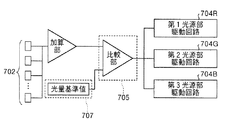
図4に、各光源部駆動回路304R、304G、304Bを制御するための構成のブロック図を示す。各光源部駆動回路304R、304G、304Bは、各光源部の温度変化量と、記憶部307に記憶されている各色光の光量シフト量との関係に基づいて制御される。各温度検出部102R、102G、102Bは、それぞれ各光源部301R、301G、301Bの温度を検出し、検出した温度に応じた信号を制御部305の波長シフト量計算部に出力する。波長シフト量計算部では、各色光について、記憶部307にデータとして記憶されている各光源部301R、301G、301Bの温度変化量と、各色光の波長領域のシフト量との関係(図4において、「温度−波長換算データ」と示す。)が参照される。これにより、制御部305は、各色光について、波長シフト量を算出する。
FIG. 4 shows a block diagram of a configuration for controlling each of the light source
波長シフト量計算部は、算出した波長シフト量に応じた信号を光量算出部に出力する。光量算出部では、各色光について、記憶部307にデータとして記憶されている波長シフト量と、ホワイトバランスの調整を行うための各色光の光量シフト量との関係(図4において、「波長−光量換算データ」と示す。)が参照される。これにより、制御部305は、各色光について、光量シフト量を算出する。
The wavelength shift amount calculation unit outputs a signal corresponding to the calculated wavelength shift amount to the light amount calculation unit. In the light amount calculation unit, for each color light, the relationship between the wavelength shift amount stored as data in the
制御部305は、算出した光量シフト量に応じた信号を、各光源部駆動回路304R、304G、304Bにそれぞれ出力する。各光源部駆動回路304R、304G、304Bは、制御部305からの光量シフト量に応じた信号により制御される。このようにして、制御部305は、各温度検出部102R、102G、102Bにより検出された温度変化量と、記憶部307に記憶されている各色光の光量シフト量との関係に基づいて、各光源部駆動回路304R、304G、304Bを制御する。
The
次に、制御部305の制御によるホワイトバランスの調整について説明する。図5に、横軸に波長(単位nm)、縦軸に強度(任意単位)をとって各色光用LEDの波長特性を示す。プロジェクタ300は、各色光用LEDからの図5で示すそれぞれの波長特性を有する色光をスクリーン140に投写する。観察者は、R光、G光及びB光の各波長特性の光を積分して認識する。全ての色は、R光、G光及びB光の加色混合により得られる。これにより、スクリーン140でフルカラーの投写像を得られる。
Next, white balance adjustment by the control of the
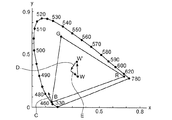
図6に、xy色度図を示す。すべての色は、R、G、Bの各強度比(刺激値)を座標表示することにより、三次元空間上に表される(RGB表色系)。各色光の刺激値は、混合した色が色温度4800Kの白色に見えるときに必要な各色の輝度を1とし、それに対する相対比で表される。RGB表色系の三次元空間からすべての色度を正の値で表わせるよう座標軸を適当に変換したのが、XYZ表示系である。三次元空間であるXYZ表示系をXY面上に投影したものがxy色度図である。xy色度図には、色の要素のうち明度に係る情報を除外して、色相と彩度のみが表される。図6に示す点RはR光用LEDからのR光、点GはG光用LEDからのG光、点BはB光用LEDからのB光、点Wは、ホワイトバランス点をそれぞれ示す。 FIG. 6 shows an xy chromaticity diagram. All colors are represented on a three-dimensional space by displaying coordinates of R, G, B intensity ratios (stimulus values) (RGB color system). The stimulus value of each color light is expressed as a relative ratio to the luminance of each color required when the mixed color looks white at a color temperature of 4800K. The XYZ display system is obtained by appropriately converting the coordinate axes so that all chromaticities can be expressed as positive values from the three-dimensional space of the RGB color system. An xy chromaticity diagram is obtained by projecting an XYZ display system, which is a three-dimensional space, onto an XY plane. In the xy chromaticity diagram, only the hue and the saturation are represented by excluding the information relating to the lightness among the color elements. The point R shown in FIG. 6 is the R light from the R light LED, the point G is the G light from the G light LED, the point B is the B light from the B light LED, and the point W is the white balance point. .
LEDの波長特性は、環境温度、特に発光チップ部の温度の上昇に対応して長波長側にシフトする。R光用LEDの波長特性は、発光チップ部の温度が1℃上昇すると略0.05nm、G光用LED及びB光用LEDの波長特性は、温度が1℃上昇すると略0.04nm長波長側にシフトする。例として、B光用LEDを有する第3光源部301Bの温度が上昇した場合を考える。図5の矢印I及び図6の矢印Cに示すように、B光用LEDの温度上昇に対応して、B光用LEDからのB光の波長特性は長波長側にシフトする。B光用LEDからのB光の波長特性が長波長側にシフトすると、図6に示すホワイトバランス点Wは、点W’にシフトする。ホワイトバランス点がW’にシフトすることにより、点Wに示す各色光の光量バランスでは白色を得られないこととなる。
The wavelength characteristic of the LED shifts to the longer wavelength side in response to an increase in environmental temperature, particularly the temperature of the light emitting chip portion. The wavelength characteristics of the LED for R light are about 0.05 nm when the temperature of the light emitting chip portion is raised by 1 ° C., and the wavelength characteristics of the LEDs for G light and B light are about 0.04 nm long wavelength when the temperature is raised by 1 ° C. Shift to the side. As an example, let us consider a case where the temperature of the third
記憶部307には、第3光源部301Bの温度変化量と、B光の波長シフト量と、ホワイトバランスの調整を行うためのR光、G光及びB光の光量シフト量とが記憶されている。制御部305は、第3光源部301Bの温度変化量と、記憶部307に記憶されているR光、G光及びB光の光量シフト量との関係に基づき、ホワイトバランスが元の位置Wとなるように各光源部駆動回路304R、304G、304Bを制御する。具体的には、B光の光量を増加し(矢印E)、さらにR光又はG光を増加することにより(矢印D)、ホワイトの色度座標を点W’から点Wへ戻るようにする。
The
本実施形態では、上述のように各温度検出部102R、102G、102Bで検出された温度変化量と、ホワイトバランスの調整を行うための各色光の光量シフト量との関係に基づいて、各光源部301R、301G、301Bからの各色光の光量を制御する。これにより、各光源部301R、301G、301Bの温度変化に伴う色むらを低減すると同時に、自然な色の画像を正確に再現することができるという効果を奏する。また、記憶部307に記憶された各光源部の温度と各色光の光量シフト量との関係に基づいて各光源部からの各色光の光量を制御することにより、ホワイトバランスを一定に保ち、自然な色の画像を正確に再現した投写像を得られるという効果を奏する。
In the present embodiment, as described above, each light source is based on the relationship between the temperature change amount detected by each
なお、本実施形態に係るプロジェクタ300は、第1実施形態に係るプロジェクタ100と同様、各光源部301R、301G、301Bの温度変化に伴い、スクリーン140において各色光の輝度分布が略均一となるように、各色光用空間光変調装置110R、110G、110Bを制御する構成としても良い。これにより、正確な色再現を行うとともに、各光源部の温度変化に伴う色むらを低減することができるという効果を奏する。
Note that, similarly to the
(第3実施形態)
図7は、本発明の第3実施形態に係るプロジェクタの概略構成を示す。第1実施形態と同一の部分には同一の符号を付し、重複する説明は省略する。第3実施形態に係るプロジェクタ700の特徴は、光検出部を有することである。プロジェクタ700は、第1色光であるR光を供給する第1光源部701Rと、第2色光であるG光を供給する第2光源部701Gと、第3色光であるB光を供給する第3光源部701Bとを有する。第1光源部701R、第2光源部701G及び第3光源部701Bは、固体発光素子であるLEDを有する。第1光源部701Rは、第1光源部駆動回路704Rにより駆動される。第2光源部701Gは、第2光源部駆動回路704Gにより駆動される。第3光源部701Bは、第3光源部駆動回路704Bにより駆動される。
(Third embodiment)
FIG. 7 shows a schematic configuration of a projector according to the third embodiment of the invention. The same parts as those in the first embodiment are denoted by the same reference numerals, and redundant description is omitted. A feature of the
各光源部701R、701G、701Bから供給される各色光は、それぞれ偏光変換素子103R、103G、103Bを透過した後、各色光用空間光変調装置110R、110G、110Bに入射する。各色光用空間光変調装置110R、110G、101Bは、それぞれ各光源部701R、701G、701Bからの光を画像信号に応じて変調する。クロスダイクロイックプリズム112は、各色光用空間光変調装置110R、110G、110Bでそれぞれ変調されたR光、G光及びB光を合成する。投写レンズ130は、クロスダイクロイックプリズム112で合成された光をスクリーン140に投写する。
The color lights supplied from the
プロジェクタ700は、投写レンズ130の射出側端面近傍に、単レンズから構成される検出光学系708を有する。検出光学系708は、投写レンズ130からスクリーン140に投写されたR光、G光及びB光を、それぞれ光検出部702に導く機能を有する。光検出部702は、R光、G光及びB光のそれぞれの輝度分布を検出する。各色光の輝度分布の検出タイミング、手順については後述する。制御部705は、光検出部702により検出されるR光、G光及びB光のそれぞれの輝度分布に基づき、R光、G光及びB光のそれぞれの輝度分布が略同一となるように各色光用空間光変調装置110R、110G、110Bを制御する。これにより、各色光の明るさを一定に保ち、色むらが低減されたプロジェクタ700を得られるという効果を奏する。なお、記憶部707については後述する。
The
また、上記構成に加えて、第1実施形態のプロジェクタ100と同様に、各色光用空間光変調装置110R、110G、110Bを制御する構成としても良い。各色光用空間光変調装置は、各光源部の温度と各色光の輝度分布との関係に基づいて、スクリーン140において各色光の輝度分布が略均一なるように制御される。これにより、各光源部の温度変化に伴う色むらを低減することができるという効果を奏する。また、検出光学系708の位置は、投写レンズ130の射出側端面近傍に限られず、スクリーン140に投写された光を光検出部702に導くことができる位置であれば良い。
In addition to the above-described configuration, the color light spatial
以下、光検出部702により検出される各色光の輝度分布に基づいて、各色光の輝度分布を略同一とする制御の手順について説明する。まず、R光を代表例にして手順を説明する。R光の輝度分布を検出する場合は、第1光源部701Rを点灯し、第2光源部701Gと第3光源部701Bとを消灯する。なお、第2光源部701Gと第3光源部701Bとを点灯させたままの状態で、シャッター機構等によりG光とB光とを遮光する構成としても良い。さらに、第2光源部701Gと第3光源部701Bとを点灯させたままの状態で、スクリーン140にG光、B光を投写しないように、G光用空間光変調装置110G、B光用空間光変調装置110Bを駆動しても良い。例えば、第1光源部701Rから供給されるR光のみを、全画素にわたり最高輝度の階調でスクリーン140に投写するように、R光用空間光変調装置110Rを駆動する場合を考える。この時、R光のみが最大輝度でスクリーン140全体に投写される。検出光学系708は、スクリーン140に投写されているR光を光検出部702に導く。
Hereinafter, based on the luminance distribution of each color light detected by the
図8は、R光を全画素にわたり最高輝度でスクリーン140に投写する場合に、光検出部702で検出される輝度分布の例を表したものである。光検出部702は、例えば、CCD、CMOSセンサ、又はフォトダイオードアレイが4行7列のマトリクス状に配列されている。
FIG. 8 shows an example of the luminance distribution detected by the
各センサ素子は、スクリーン140に投写され、検出光学系708により導かれたR光を検出する。各センサ素子において、領域ARA1は最も検出された輝度が高い状態、領域ARA4は最も検出された輝度が低い状態、領域ARA2、領域ARA3はこれらの中間の輝度の状態を示している。スクリーン140における輝度分布は、各色光用空間光変調装置110R、110G、110Bの画素数に対応する分解能で分布している。これに対して、光検出部702上においては、各センサ素子の数に対応した分解能(図8の場合、4×7個)で輝度分布が検出される。
Each sensor element detects the R light projected on the
図9(a)、(b)に、図8のA−A’上にあるセンサ素子が検出した階調ヒストグラムをグラフで示す。図9に示すグラフの縦軸はR光の階調レベル、横軸は光検出部702のA−A’上のセンサ素子の位置を示す。図9(a)に示すように、各センサ素子が検出したR光の階調レベルは、248階調から255階調にわたる。
FIGS. 9A and 9B are graphs showing gradation histograms detected by the sensor elements on A-A ′ in FIG. 8. The vertical axis of the graph shown in FIG. 9 indicates the gradation level of the R light, and the horizontal axis indicates the position of the sensor element on A-A ′ of the
制御部705は、A−A’上に対応するR光用空間光変調装置110Rの画素について、検出値のうち最低値である248階調となるようにR光用空間光変調装置110Rの駆動を制御する。図9(b)は、R光用空間光変調装置110Rの画素のうち、248階調以上の階調を示すセンサに対応する画素について、248階調となるように斜線を付して示す部分に対応する輝度レベルを減少させる。これにより、A−A’上にあるセンサ素子に対応する画素について、R光の輝度分布を略均一にすることができる。また、A−A’上にあるセンサに対応する画素についてのみならず、R光用空間光変調装置110Rの全画素について同様の処理を行う。これにより、制御部705は、R光用空間光変調装置110Rの全画素について、R光の輝度分布を一定とすることができる。
The
本実施形態のプロジェクタ700では、R光について、全画素が最高輝度となるようにR光用空間光変調装置110Rを駆動し、このときの輝度分布を用いてR光の輝度分布を制御している。最高輝度となるようにR光用空間光変調装置110Rを駆動していることから、全画素について、検出された輝度よりも高い階調にすることはできない。このため、各センサ素子による検出値のうち、最低値の階調で統一するようにR光用空間光変調装置110Rを制御することが望ましい。
In the
R光の輝度むらを検出するためには、上述のように、R光を最高輝度でスクリーン140に投写するようにR光用空間光変調装置110Rを駆動することにより行う。R光の輝度分布を検出する場合、G光用空間光変調装置110G、B光用空間光変調装置110Bは、G光、B光をスクリーン140に投写しないように駆動する。また、シャッター機構等によりG光とB光とを遮光する構成としても良い。さらに、第1光源部701Rを点灯し、第2光源部701G及び第3光源部701Bを消灯することとしても良い。
In order to detect the luminance unevenness of the R light, as described above, the R light spatial
以上説明したように、制御部705は、光検出部702により検出したR光の輝度分布に基づいて、R光用空間光変調装置110Rを制御する。G光、B光についてもR光と同様に、制御部705は、光検出部702により検出したG光及びB光のそれぞれの輝度分布に基づいて、G光用空間光変調装置110G及びB光用空間光変調装置110Bを制御する。これにより、R光、G光及びB光の輝度分布を均一にし、投写像の色むらを低減することができるという効果を奏する。
As described above, the
なお、プロジェクタ700に記憶部を設け、予め輝度分布を均一にする各色光用空間光変調装置の制御情報データを記憶させることとしても良い。例えば、プロジェクタ700の出荷時に、上記と同様の手順で各色光の輝度分布を検出する。そして、R光、G光及びB光のそれぞれの輝度分布が均一となるように各色光用空間光変調装置を制御する。記憶部は、各色光のそれぞれの輝度分布を均一にする各色光用空間光変調装置の制御情報データを記憶する。制御部705は、制御情報データに基づいて、各色光用空間光変調装置110R、110G、110Bを制御することができる。これにより、常に色むらが少なく明るさが均一な投写像を得られるという効果を奏する。
In addition, a storage unit may be provided in the
また、プロジェクタ700の出荷時に、プロジェクタ700が有する光検出部702を用いる光検出よりもさらに精密な他の手段を用いて光検出することとしても良い。これにより、記憶部には、各色光のそれぞれの輝度分布を均一にする各色光用空間光変調装置の制御についてさらに精密なデータを記憶させることで、色むらを確実に低減できるという効果を奏する。
In addition, when the
また、光検出部702により各色光の輝度分布の検出を行うタイミングは、適宜設定可能である。例えば、光源発光時に光検出部702による各色光の輝度分布の検出を行い、その後は映像表示をしない時に数分間隔を目安に行うこととしても良い。これにより、常に色むらの少ない投写像を得られるという効果を奏する。
The timing at which the
次に、光検出部702で検出する各色光の輝度分布に応じて、各色光の輝度分布を略同一とする他の制御例を説明する。図8に示す光検出部702の各センサ素子の大きさは、空間光変調装置の複数の画素の大きさに対応する。例えば、1つのセンサ素子の領域に対し、空間光変調装置の100×100個の画素の領域が対応している。図9を用いた上記説明では、1つのセンサ素子に対応する全ての画素について、空間光変調装置を略同一に制御することとしている。本制御例では、光検出部702に有するセンサのうち、隣接するセンサどうしが互いに異なる検出値であった場合を考える。
Next, another control example in which the luminance distribution of each color light is made substantially the same according to the luminance distribution of each color light detected by the
例えば、図8に示すセンサ素子702aで検出した階調レベルは255階調、センサ素子702aに隣接するセンサ素子702bで検出した階調レベルは253階調と、互いの検出値には2階調の差がある(図9参照)。全画素の階調レベルを一律に248階調とするために、R光用空間光変調装置110Rは、センサ素子702aの領域に対応する画素では7階調下げる制御、センサ素子702bの領域に対応する画素では5階調下げる制御がなされる。このとき、センサ素子702aとセンサ素子702bとの境界線部分に対応する画素においては、制御により差し引かれる階調レベルに2階調の差がある。このため、投写像において、センサ素子702aとセンサ素子702bとの境界線部分に対応する部分では、輝度レベルに階段的な差が生じてしまう。
For example, the gradation level detected by the
そこで、制御部705による輝度レベルの段差の発生を防ぐ制御例について説明する。光検出部702の各センサ素子の検出値(階調レベル)を、該センサ素子の領域の中央に対応する画素に当てはめる。隣り合うセンサ素子の検出値が異なる場合には、センサ素子の領域の中央に対応する画素からセンサ素子の境界線に対応する画素に対して補間値を算出し、R光用空間光変調装置110Rを制御する。
Therefore, a control example for preventing the occurrence of a level difference in luminance level by the
例えば、図9に示す検出結果により、センサ素子702aの領域の中央に対応する画素の階調レベルに255階調、センサ素子702bの領域の中央に対応する画素の階調レベルに253階調の値を当てはめる。センサ素子702aの領域の中央に対応する画素と、センサ素子702bの領域の中央に対応する画素との間にある画素については、センサ素子702aの領域の中央にある画素の255階調と、センサ素子702bの領域の中央にある画素の253階調の値とを補間して得られた値を当てはめる。センサ素子702aの領域の中央に対応する画素と、センサ素子702bの領域の中央に対応する画素との間にある画素については、算出された補間値を用いてR光用空間光変調装置110Rの制御を行う。補間値を用いることにより、投写像において、センサ702aとセンサbとの境界線部分に対応する部分の輝度段差発生を防ぐことができる。
For example, the detection result shown in FIG. 9 indicates that the gradation level of the pixel corresponding to the center of the
図10は、補間した階調レベルを示す。図8に示すA−A’上にあるセンサ素子について、図9に示す輝度分布に基づく補間値Hを用いて一定階調となるように所定階調レベルを差し引く処理を行う。図10において、一定階調レベルである248階調となるように低減される階調レベルを、斜線を付した部分で表す。補間値Hを用いて空間光変調装置を制御することにより、輝度段差の発生を防止できる。これにより、輝度むらを低減し、色むらの少ない投写像を得られるという効果を奏する。補間値Hの算出には、例えば、直線近似、2次曲線近似、スプライン補間のいずれを用いても良い。 FIG. 10 shows the interpolated gradation level. For the sensor elements on A-A ′ shown in FIG. 8, a process of subtracting a predetermined gradation level so as to obtain a constant gradation is performed using the interpolation value H based on the luminance distribution shown in FIG. 9. In FIG. 10, the gradation level that is reduced to 248 gradations, which is a constant gradation level, is represented by the hatched portion. By controlling the spatial light modulator using the interpolation value H, it is possible to prevent the occurrence of a luminance step. As a result, the luminance unevenness is reduced and a projection image with little color unevenness can be obtained. For the calculation of the interpolation value H, for example, any of linear approximation, quadratic curve approximation, and spline interpolation may be used.
なお、図8において、光検出部702に有するセンサは、光検出部702の光照射面の長辺方向に7個、短辺方向に4個設け、合計数量を28個として示しているが、センサの数量はこれに限られない。センサの数量は、最低2個から、最大は空間光変調装置の画素数と同数までにおいて、適宜設定可能である。センサの数量は多いほど正確に輝度分布を検出できるので、確実に色むらを低減することができる。
In FIG. 8, the sensor included in the
また本実施形態のプロジェクタ700は、第1実施形態のプロジェクタ100と同様、光検出部702による検出値に基づいて階調補正値を適宜変更して使用することとしても良い。光検出部702による検出値に基づいて階調補正値を変更して使用することにより、スクリーン140においてR光、G光、及びB光のそれぞれの輝度分布が略均一となるように空間光変調装置を制御する。これにより、色むらが少なく、かつカラーバランスが良好なプロジェクタを得られるという効果を奏する。さらに、階調補正値を変更して使用するのではなく、階調補正とは別に、光検出部702による検出値に基づいて空間光変調装置を制御することとしても良い。この場合、光検出部702による検出値に基づく制御は、階調補正の前に行っても、後に行っても良い。
Further, the
次に、第3実施形態の変形例として、光検出部702からの検出値により各光源部の光量を安定化するための構成につき説明する。図11に、光検出部702による検出値により、第1光源部701R、第2光源部701G及び第3光源部701Bが供給する各色光の光量を安定化するための構成のブロック図を示す。光検出部702が有する全てのセンサ素子からの検出値は、加算部で加算され、制御部705に出力される。全てのセンサ素子からの検出値を加算した値は、いずれかの光源部から発生した色光の光量値である。制御部705は、比較部において、加算部から出力される加算結果と、記憶部707に記憶されている各光源部の光量基準値とを比較して差分を算出する。制御部705は、比較部で算出された比較結果に基づき、各光源部駆動回路704R、704G、704Bを制御する。
Next, as a modification of the third embodiment, a configuration for stabilizing the light amount of each light source unit by the detection value from the
各光源部の光量基準値は、例えば、プロジェクタ700の出荷時に記憶部707に記憶させることができる。このように、各センサ素子からの領域に対応した階調レベルに限定されず、これらの階調レベルを全て加算した積分値を用いることもできる。これにより、各光源部からの各色光の光量を安定にし、カラーバランスが良好なプロジェクタ700を得られるという効果を奏する。また、光源部の光量を安定化するタイミングも、上記空間光変調装置の制御と同様、適宜変更可能である。さらに、各色光用空間光変調装置の制御と合わせて各色光の光量安定化を行うことにより、カラーバランスを良好にし、かつ投写像の色むらを低減することができるという効果を奏する。
The light quantity reference value of each light source unit can be stored in the
また、本実施形態のプロジェクタ700は、空間光変調装置として3つの液晶表示装置を有する。しかし、これに限らずプロジェクタ700は、1つの液晶表示装置を有する構成とすることもできる。1つの液晶表示装置を有する場合、単独の光源部のみ、例えば第1光源部701Rのみを点灯し、第2光源部701G及び第3光源部710Bを消灯する。その間に、R光について全画素について階調が同じとなるように液晶表示装置を駆動する。光検出部702は、スクリーン140に投写されるR光を検出し、輝度分布が略均一となるように液晶表示装置を制御する。G光、B光についても同様にして液晶表示装置を制御する。これにより、色むらの低減されたプロジェクタ700を得られるという効果を奏する。
In addition, the
1つの液晶表示装置を有する場合、各光源部は1フレーム期間において順次点灯される。例えば、映像の1フレームは、第1光源部701Rを点灯させるサブフレームと、第2光源部701Gを点灯させるサブフレームと、第3光源部701Bを点灯させるサブフレームとから構成される。そして、R光のサブフレームと、G光のサブフレームと、B光のサブフレームとを順次表示することでフルカラー像を得ることができる。ここで、各光源部の点灯期間である各サブフレームに同期して、光検出部702は1フレーム期間で各色光を検出することができる。また、1フレーム期間に全ての3色光について検出をせず、複数のフレームに分けて3色光の光量を検出することとしても良い。例えば1フレーム目においては、光検出部702はR光を検出し、R光について液晶表示装置の駆動を制御する。次のフレームでG光の検出、及び上記制御を行う。最後に、G光の制御後にさらに次のフレームでB光の検出、制御を行うようにしても良い。このような制御は、各センサ素子の検出速度が遅い場合、信号の処理速度が遅い場合に確実に色むらを低減することができるという効果を奏する。
In the case of having one liquid crystal display device, each light source unit is sequentially turned on in one frame period. For example, one frame of an image is composed of a subframe that turns on the first
(第4実施形態)
図12は、本発明の第4実施形態に係るプロジェクタの概略構成を示す。第1実施形態及び第3実施形態と同一の部分には同様の符号を付し、重複する説明は省略する。本実施形態に係るプロジェクタ1200は、第3実施形態に係るプロジェクタ700と同様、R光、G光及びB光のそれぞれの輝度分布を検出するための光検出部702を有する。プロジェクタ1200の特徴は、光分岐部を有することである。
(Fourth embodiment)
FIG. 12 shows a schematic configuration of a projector according to the fourth embodiment of the invention. The same parts as those in the first embodiment and the third embodiment are denoted by the same reference numerals, and redundant description is omitted. Similar to the
クロスダイクロイックプリズム112は、各色光用空間光変調装置110R、110G、110Bによる変調光を合成して射出する。合成された光は、光分岐部であるビームスプリッタ1220に入射する。ビームスプリッタ1220は、クロスダイクロイックプリズム112を介し各色光用空間光変調装置110R、110G、110Bと投写レンズ130との間の光路中に設けられている。
The cross
ビームスプリッタ1220は、光束分割面1220aを有する。光束分割面1220aは、偏光方向に関わりなく、R光、G光、B光を所定の強度比で分割する。例えば、光束分割面1220aは、入射するR光、G光、B光の90%を透過し、10%を反射する。光束分割面1220aを反射した光は、光路を90度折り曲げられ、光検出部702の方向に進行する。このようにして、ビームスプリッタ1220は、各色光用空間光変調装置110R、110G、110Bで変調されたR光、G光、B光をそれぞれ投写レンズ130の方向と光検出部702の方向とに分岐する。
The
光検出部702は、ビームスプリッタ1220により分岐された光から、R光、G光及びB光のそれぞれの輝度分布を検出する。例えば、R光の輝度分布を検出する場合は、第1光源部701Rを点灯し、第2光源部701Gと第3光源部701Bとを消灯する。また、全ての光源部701R、701G、701Bを点灯した状態で、G光用空間光変調装置110GとB光用空間光変調装置110Bとを遮光するように制御しても良い。このようにして、R光のみの輝度分布を検出できる。G光、B光の輝度分布を検出する場合も同様にして、所望の色光のみが光検出部702に入射するようにする。そして、制御部1205は、光検出部702により検出された各色光の輝度分布が略均一となるように各色光用空間光変調装置110R、110G、110Bをそれぞれ制御する。ビームスプリッタ1220が、分岐光を光検出部702に導く構成とすることにより、光検出部702で各色光の輝度分布を検出することができる。これにより、各色光の輝度(明るさ)を一定に保ち、色むらの低減されたプロジェクタ1200を得られるという効果を奏する。
The
(第4実施形態の変形例)
図13は、上記第4実施形態の変形例の概略構成を示す。プロジェクタ1200と同一の部分には同一の符号を付し、重複する説明は省略する。プロジェクタ1300は、クロスダイクロイックプリズム112の射出側に、光分岐部として回折素子1320を有する。クロスダイクロイックプリズム112は、各色光用空間光変調装置110R、110G、110Bにより変調された光を合成し、回折素子1320側に入射させる。回折素子1320は、クロスダイクロイックプリズム112を介し、各色光用空間光変調装置110R、110G、110Bと投写レンズ130との間の光路中に設けられる。回折素子1320には、例えば、ブレーズ式回折格子を用いることができる。
(Modification of the fourth embodiment)
FIG. 13 shows a schematic configuration of a modified example of the fourth embodiment. The same parts as those of the
回折素子1320は、偏光方向に関わりなく、R光、G光、B光を所定の強度比で回折する。例えば、回折素子1320は、入射するR光、G光、B光の90%を投写レンズ130の方向に透過(0次光)させ、10%を投写レンズ130以外の方向に回折(±1次回折光)させる。回折素子1320で回折された光は、光検出部702に入射する。
The
このようにして、回折素子1320は、各色光用空間光変調装置110R、110G、110Bで変調されたR光、G光、B光をそれぞれ投写レンズ130の方向と光検出部702の方向とに分岐する。光検出部702は、回折素子1320により分岐された光を検出する。制御部1305は、光検出部702により検出された各色光の輝度分布が略均一となるように各色光用空間光変調装置110R、110G、110Bをそれぞれ制御する。光分岐部である回折素子1320が、分岐光を光検出部702に導く構成とすることにより、光検出部702で各色光の輝度分布を検出することができる。これにより、各色光の明るさを一定に保ち、色むらの低減されたプロジェクタ1300を得られるという効果を奏する。
In this way, the
(第5実施形態)
図14は、本発明の第5実施形態に係るプロジェクタの概略構成を示す。第1実施形態及び第3実施形態と同一の部分には同様の符号を付し、重複する説明は省略する。本実施形態に係るプロジェクタ1400は、第4実施形態で説明したプロジェクタ1200、1300と同様に、R光、G光及びB光のそれぞれの輝度分布を検出するための光検出部と、光検出部の方向に光を分岐する光分岐部とを有する。本実施形態に係るプロジェクタ1400の特徴は、各色光について、各光源部と各色光用空間光変調装置との間の光路中に、光分岐部が設けられていることである。
(Fifth embodiment)
FIG. 14 shows a schematic configuration of a projector according to the fifth embodiment of the invention. The same parts as those in the first embodiment and the third embodiment are denoted by the same reference numerals, and redundant description is omitted. A
第1光源部701Rから供給されるR光を代表例として説明する。第1光源部701RからのR光は、偏光変換素子103Rに入射する。偏光変換素子103Rは、入射するR光を特定の偏光方向、例えばp偏光光に変換する。ここで、偏光変換素子103Rの光学特性により、入射したR光を全てp偏光光に変換することは困難である。このため、偏光変換素子103Rを射出したR光の一部にはs偏光光が混在している。第1色光用光分岐部であるR光用回折素子1420Rは、偏光変換素子103Rを射出したR光のうち特定の振動方向を有する偏光光を回折することで分岐する。
The R light supplied from the first
図15に、R光用回折素子1420Rの概略構成を示す。R光用回折素子1420Rは、ガラスGLAと光学異方性物質Mとを接合して構成されている。接合面においては、回折溝Nが形成されている。光学異方性物質Mは、回折溝Nの長手方向に沿った方向(以下、「回折溝方向」という。)に振動する偏光と、回折溝方向に垂直な方向に振動する偏光とで、屈折率が異なる。光学異方性物質Mとしては、例えば、ニオブ酸リチウム、液晶等を用いることができる。
FIG. 15 shows a schematic configuration of the R-
R光用回折素子1420RのガラスGLAの屈折率は1.5である。また、光学異方性物質Mについては、回折溝方向に振動する偏光光に対する屈折率は1.5、回折溝方向に垂直な方向に振動する偏光光に対する屈折率は1.8である。ここで、R光用回折素子1420Rは、回折溝方向とp偏光光の振動方向とが略一致するように配置されている。この場合、p偏光光については、ガラスGLAと光学異方性物質Mとの間では屈折率差がない。従って、p偏光光は回折溝Nで回折することなく透過する。これに対して、回折溝方向に垂直な方向に振動する偏光光、即ちs偏光光については、ガラスGLAと光学異方性物質Mとでは屈折率が異なるため、回折溝Nで回折される。これにより、R光用回折素子1420Rは、偏光変換素子103Rを射出したR光のうちの一部であるs偏光光を回折することで分岐する。
The refractive index of the glass GLA of the diffraction element for
R光用回折素子1420Rは、入射するR光のうちp偏光光をR光用空間光変調装置110Rの方向に透過(0次光)させ、s偏光光をR光用空間光変調装置110R以外の方向に回折させる。R光用空間光変調装置110Rの方向に透過するp偏光光であるR光は、R光用空間光変調装置110Rにより画像信号に応じて変調され、s偏光光に変換される。R光用空間光変調装置110Rでs偏光光に変換されたR光は、クロスダイクロイックプリズム112に入射する。
The R
R光用回折素子1420RでR光用空間光変調装置110R以外の方向に回折されたs偏光光は、R光用光検出部1402Rの方向に進行する。このようにして、R光用回折素子1420Rは、第1光源部701Rから供給された光をR光用空間光変調装置110Rの方向と光検出部1402Rの方向とに分岐する。光検出部1402Rは、R光用回折素子1420Rにより分岐された光を検出する。制御部1405は、R光用光検出部1402Rにより検出されたR光の輝度分布が略均一となるようにR光用空間光変調装置110Rを制御する。
The s-polarized light diffracted by the R
次に、第2光源部701Gから供給されるG光について説明する。第2光源部701GからのG光は、偏光変換素子103Gに入射する。偏光変換素子103Gは、例えば、入射するG光を略s偏光光に変換する。G光用回折素子1420Gは、回折溝方向とs偏光光の振動方向とが略一致するように配置されている。この場合、s偏光光については、ガラスGLAと光学異方性物質Mとの間では屈折率差がない。従って、s偏光光は回折溝Nで回折することなく透過する。これに対して、回折溝方向に垂直な方向に振動する偏光光、即ちp偏光光については、ガラスGLAと光学異方性物質Mとでは屈折率が異なるため、回折溝Nで回折される。これにより、G光用回折素子1420Gは、偏光変換素子103Gを射出したG光のうちの一部であるp偏光光を回折することで分岐する。
Next, the G light supplied from the second
G光用回折素子1420GからG光用空間光変調装置110Gの方向に進行したG光は、G光用空間光変調装置110Gで画像信号に応じて変調され、p偏光光に変換される。G光用空間光変調装置110Gでp偏光光に変換されたG光は、クロスダイクロイックプリズム112に入射する。また、G光用回折素子1420Gで回折されたp偏光光は、R光の説明と同様に、G光用光検出部1402Gで検出される。制御部1405は、光検出部1402Gにより検出されたG光の輝度分布が略均一となるようにG光用空間光変調装置110Gを制御する。
The G light traveling in the direction from the G
第3光源部701Bから供給されるB光について説明する。第3光源部701BからのB光は、偏光変換素子103Bに入射する。偏光変換素子103Bは、例えば、入射するB光を略p偏光光に変換する。第3色光用光分岐部であるB光用回折素子1420Bは、R光用回折素子1420Rと同様に、p偏光光を透過し、s偏光光を回折する。
The B light supplied from the third
B光用回折素子1420BからB光用空間光変調装置110Bの方向に直進したB光は、B光用空間光変調装置110Bで画像信号に応じて変調され、s偏光光に変換される。B光用空間光変調装置110Bでs偏光光に変換されたB光は、クロスダイクロイックプリズム112に入射する。B光用回折素子1420Bで回折されたs偏光光は、R光の説明と同様に、B光用光検出部1402Bで検出される。制御部1405は、光検出部1402Bにより検出されたB光の輝度分布が略均一となるようにB光用空間光変調装置110Bを制御する。
The B light that has traveled straight from the B light
各色光用光分岐部である回折素子1420R、1420G、1420Bが、回折光を各光検出部1402R、1402G、1402Bにそれぞれ導く構成とすることにより、各光検出部で各色光の輝度分布を検出することができる。これにより、各色光の明るさを一定に保ち、色むらの少ないプロジェクタ1400を得られるという効果を奏する。また、各光検出部による検出には、各偏光変換素子で特定の偏光方向に変換されていない光を利用している。特定の偏光方向に変換されていない光は、空間光変調装置において正確な変調がなされないため、投写像のコントラストを低下させる要因となる。このため、光路中に回折素子1420R、1420G、1420Bを配置することによって、投写像を形成する光を減少させることもない。これにより、スクリーン140の投写像の明るさを損なうことなく色むらを低減することができるという効果を奏する。また、特定の偏光方向に変換しない光の成分を積極的に作り出して、この成分の光の輝度を検出しても良い。
The
なお、各色光用回折素子1420R、1420G、1420Bの機能は、第1偏光板(図1参照)の機能を兼用する構成としても良い。第1偏光板は、特定の振動方向を有する偏光光を透過するため、本実施形態の各色光用回折素子1420R、1420G、1420Bで第1偏光板の機能を兼用することができる。これにより、構成部品数を減少し、簡易な構成で色むらを低減することができるという効果を奏する。
Note that the functions of the color
(第6実施形態)
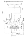
図16は、本発明の第6実施形態に係るプロジェクタの概略構成を示す。第1実施形態及び第3実施形態と同一の部分には同様の符号を付し、重複する説明は省略する。本実施形態に係るプロジェクタ1600は、空間光変調装置としてティルトミラーデバイスを用いる。
(Sixth embodiment)
FIG. 16 shows a schematic configuration of a projector according to the sixth embodiment of the invention. The same parts as those in the first embodiment and the third embodiment are denoted by the same reference numerals, and redundant description is omitted. The
プロジェクタ1600は、R光を供給する第1光源部1601Rと、G光を供給する第2光源部1601Gと、B光を供給する第3光源部1601Bとを有する。第1光源部1601R、第2光源部1601G、及び第3光源部1601Bは、固体発光素子であるLEDを有する。各光源部は、投写レンズ130の入射側端面の近傍に配置される。
The
各光源部から供給される光は、ティルトミラーデバイスである空間光変調装置1610に入射する。空間光変調装置1610は、入射光を画像信号に応じて変調する。ティルトミラーデバイスの例の一つは、テキサス・インスツルメンツ社のディジタルマイクロミラーデバイス(DMD)である。空間光変調装置1610で変調された光は、投写レンズ130の方向へ射出される。投写レンズ130は、空間光変調装置1610から射出される光をスクリーン140に投写する。
Light supplied from each light source unit enters a
空間光変調装置1610は、複数の可動ミラー素子を有する。可動ミラー素子は、画像信号に応じて第1の反射位置と第2の反射位置とに択一的に移動し、入射光を投写レンズ130の方向(ON)又は投写レンズ130以外の方向(OFF)に反射させる。可動ミラー素子1610aは、第1の反射位置の場合、入射光を投写レンズ130の方向に反射する。可動ミラー素子1610bは、第2の反射位置の場合、入射光を投写レンズ130以外の方向に反射する。投写レンズ130の方向に進行する光L1は、スクリーン140にて投写像を形成する。投写レンズ130以外の方向に進行する光L2は、光検出部1602に入射する。
The
例えば、R光の輝度分布を検出する場合は、第1光源部1601Rのみ点灯し、全てのR光が光検出部1602に入射するように空間光変調装置1610を駆動する期間を設ける。即ち、この期間、空間光変調装置1610が有する全ての可動ミラー素子は、第2の反射位置にある。そして、この期間中にR光を検出する。G光、B光の検出に関してもR光と同様に、検出したい色光のみを点灯させ、全ての可動ミラー素子を第2の反射位置とする。これにより、光検出部1602は、R光、G光、及びB光のそれぞれの輝度分布を検出する。制御部1605は、光検出部1602により検出されたR光、G光及びB光のそれぞれの輝度分布に基づいて、R光、G光及びB光のそれぞれの輝度分布が略均一となるように空間光変調装置1610を制御する。なお、制御部1605は、空間光変調装置1610に有する可動ミラー素子の時分割駆動(サブフレーム駆動)を制御することにより、各色光の輝度分布を略均一とする。
For example, when detecting the luminance distribution of R light, only the first light source unit 1601R is turned on, and a period for driving the
光検出部1602が、空間光変調装置1610から投写レンズ130以外の方向に反射される光を検出することにより、光検出部1602で各色光の輝度分布を検出することができる。また、画像投写中に光検出部1602の方向に反射される光は、投写像の形成に不要となる成分の光である。従って、投写像を形成する光を減少させることがないので、投写光の光路中において光を分岐する構成よりもさらに明るい投写像を得られる。これにより、明るく、色むらの低減された投写像のプロジェクタ1600を得られるという効果を奏する。
When the
次に、各光源部1601R、1601G、1601Bの点灯タイミングについて説明する。投写像の1フレーム間において、各色光用LEDを順次点灯させて空間光変調装置1610を照明する。観察者は、各光源部から順次照明され、空間光変調装置1610により変調されるR光、G光、B光を積分して認識する。このため、スクリーン140上にフルカラーの投写像が得られる。R光、G光、B光を順次投写し、全体として白色の投写像を得るためには、G光の光束量を全体の光束量のうち60〜80%を要する。各色光用LEDの出力量、数量を同一とした場合、G光の光束量が不足することとなる。そこで、R光用、G光用、B光用の各LEDを同数ずつ配列した場合には、G色用LEDの点灯時間をR光用LED及びB光用LEDの点灯時間より長くする。G光用LEDをR光用LED及びB光用LEDの数よりも多く配置する場合には、G光用LEDの点灯時間を他の色光のLEDの点灯時間と同一又は短くすることも可能である。これにより、自然なフルカラーの像を得られる。
Next, lighting timings of the
(第6実施形態の第1変形例)
図17に、上記第6実施形態の第1変形例の概略構成を示す。プロジェクタ1600と同一の部分には同一の符号を付し、重複する説明は省略する。プロジェクタ1700の特徴は、反射ミラー1706を投写レンズ130の入射側端面の近傍に配置し、光検出部1702を空間光変調装置1610の近傍に配置することである。
(First Modification of Sixth Embodiment)
FIG. 17 shows a schematic configuration of a first modification of the sixth embodiment. The same parts as those of the
投写レンズ130以外の方向に進行する光L2は、投写レンズ130の入射側端面近傍に配置されている反射ミラー1706に入射する。反射ミラー1706は、入射光を光検出部1702の方向に反射する。光検出部1702は、反射ミラー1706からの反射光から、R光、G光、及びB光のそれぞれの輝度分布を順次検出する。本変形例では、光検出部1702と空間光変調装置1610とを同一基板PL上に配置できる。さらに好ましくは、光検出部1702と、空間光変調装置1610と、制御部1605とを一体として構成することもできる。これにより、プロジェクタ1700を簡易な構成とすることができるという効果を奏する。
The light L2 traveling in a direction other than the
(第6実施形態の第2変形例)
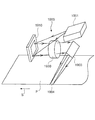
図18は、上記第6実施形態の第2変形例の概略構成を示す。プロジェクタ1600と同一の部分には同一の符号を付し、重複する説明は省略する。プロジェクタ1800は、第1光源部及び第3光源部と、第2光源部とを、投写レンズ140の光軸AXに関し略対称な位置に配置している。
(Second Modification of Sixth Embodiment)
FIG. 18 shows a schematic configuration of a second modification of the sixth embodiment. The same parts as those of the
プロジェクタ1800は、R光を供給する第1光源部1801Rと、G光を供給する第2光源部1801Gと、B光を供給する第3光源部1801Bとを有する。第1光源部1801R、第2光源部1802G、及び第3光源部1801Bは、固体発光素子であるLEDを有する。各光源部から供給される光は、ティルトミラーデバイスである空間光変調装置1810に入射する。空間光変調装置1810は、入射光を画像信号に応じて変調する。空間光変調装置1810で変調された光は、投写レンズ130の方向へ射出される。投写レンズ130は、空間光変調装置1810から射出される光をスクリーン140に投写する。
The
空間光変調装置1810は、複数の可動ミラー素子を有する。可動ミラー素子は、画像信号に応じて第1の反射位置と第2の反射位置とに択一的に移動し、入射光を投写レンズ130の方向(ON)又は投写レンズ130以外の方向(OFF)に反射させる。
Spatial
図18で示すように、第1の反射位置にある可動ミラー素子1810aは、第1光源部1801Rと第3光源部1801Bとからの入射光を投写レンズ130の方向に反射する(光L1)。また、第1の反射位置にある可動ミラー素子1810aは、第2光源部1801Gからの入射光を投写レンズ130以外の方向に反射する(光L4)。さらに、第2の反射位置にある可動ミラー素子1810bは、第2光源部1801Gからの入射光を投写レンズ130の方向に反射する(光L3)。また、第2の反射位置にある可動ミラー素子1810bは、第1光源部1801Rと第3光源部1801Bとからの入射光を投写レンズ130の方向に反射する(光L2)。投写レンズ130の方向に進行する光L1と光L3とは、スクリーン140にて投写像を形成する。
As shown in FIG. 18, the
第1光源部1801Rと第3光源部1801Bとから投写レンズ130以外の方向に進行する光L2は、光検出部1802RBに入射する。光検出部1802RBは、R光及びB光のそれぞれの輝度分布を検出する。また、第2光源部1801Gから投写レンズ130以外の方向に進行する光L4は、光検出部1802Gに入射する。光検出部1802Gは、G光の輝度分布を検出する。
Light L2 traveling in a direction other than the
例えば、R光の輝度分布を検出する場合は、第1光源部1801Rのみを点灯し、全てのR光が光検出部1802RBに入射するように空間光変調装置1810を駆動する期間を設ける。即ち、この期間、空間光変調装置1810が有する全ての可動ミラー素子は、第2の反射位置にある。そして、この期間中にR光を検出する。B光の検出に関してもR光と同様に、第3光源部1801Bのみを点灯し、全ての可動ミラー素子を第2の反射位置とする。これにより、光検出部1802RBは、R光、B光のそれぞれの輝度分布を検出する。G光の輝度分布を検出する場合は、第2光源部1801Gのみを点灯し、全てのG光が光検出部1802Gに入射するように空間光変調装置1810を駆動する期間を設ける。即ち、この期間、空間光変調装置1810が有する全ての可動ミラー素子は、第1の反射位置にある。そして、この期間中にG光を検出する。これにより、光検出部1802Gは、G光の輝度分布を検出する。このように、R光とB光との検出時と、G光の検出時とでは、可動ミラー素子の反射位置を反転させる。
For example, when detecting the luminance distribution of the R light, only the first
制御部1805は、光検出部1802RBで検出されたR光、B光と、光検出部1802Gで検出されたG光とのそれぞれの輝度分布に基づいて、R光、G光、B光のそれぞれの輝度分布が略均一となるように空間光変調装置1810を制御する。なお、本変形例に係るプロジェクタ1800の空間光変調装置1810は、可動ミラー素子の時分割駆動(サブフレーム駆動)を制御することにより、各色光の輝度分布を略均一とする。
Based on the respective luminance distributions of the R light and B light detected by the light detection unit 1802RB, and the G light detected by the
光検出部1802RBが、空間光変調装置1810から投写レンズ130以外の方向に反射されるR光、B光を検出することにより、光検出部1802RBでR光とB光の輝度分布を検出することができる。光検出部1802Gが、空間光変調装置1810から投写レンズ130以外の方向に反射されるG光を検出することにより、光検出部1802GでG光の輝度分布を検出することができる。また、画像投写中に光検出部1802RB、1802Gの方向に反射される光は、投写像の形成に不要となる成分の光である。従って、投写像を形成する光を減少させることがないので、投写光の光路中において光を分岐する構成よりもさらに明るい投写像を得られる。これにより、明るく、色むらの低減された投写像のプロジェクタ1800を得られるという効果を奏する。
The light detection unit 1802RB detects the R light and B light reflected from the spatial
本変形例のプロジェクタ1800は、第1光源部1801R及び第3光源部1801Bと、第2光源部1801Gとを、投写レンズ130の光軸AXに関し略対称な位置に配置している。これにより、各色光用LEDの配置の自由度を高くすることができる。例えば、第2光源部1801GのG光用LEDを、第1光源部1801RのR光用LED、及び第3光源部1801BのB光用LEDの数よりも多く配置することもできる。この結果、簡易な構成で良好なカラーバランスの投写像を得ることができる。このとき、可動ミラー素子の駆動極性は、G光用LEDの点灯時間と、R光用及びB光用LEDの点灯時間とで反転させる。これにより、空間光変調装置1810は、画像信号のON、OFFに応じて光変調を行い、フルカラーの投写像を得られる。
In the
(第7実施形態)
図19は、本発明の第7実施形態に係るプリンタ1900の概略構成を示す。プリンタ1900の照明装置1901は、R光を供給する第1光源部と、G光を供給する第2光源部と、B光を供給する第3光源部とを有する。第1光源部、第2光源部、及び第3光源部は、固体発光素子であるLEDを有する。また、プリンタ1900は、第1実施形態に係るプロジェクタ100と同様、温度検出部と、記憶部と、制御部(いずれも不図示)とを有する。
(Seventh embodiment)
FIG. 19 shows a schematic configuration of a
照明装置1901から供給された光は、空間光変調装置1910に入射する。空間光変調装置1910としてはDMDを用いることができる。空間光変調装置1910により反射された光は、結像レンズ1930により印画紙片P上に結像する。なお、結像レンズ1930と印画紙片Pとの間には光路を折り曲げるための反射ミラー1903が設けられている。
Light supplied from the
DMDである空間光変調装置1910は、例えば16μm四方の可動ミラー素子を1μm間隔で2次元的に基板状に配列した素子である。各可動ミラー素子をそれぞれ回転制御することにより、各可動ミラー素子に対応する領域のオン/オフを制御する。本実施形態の場合、照明装置1901から供給された光を結像レンズ1930の方向に反射するように空間光変調装置1910の可動ミラー素子を制御する。これにより、当該可動ミラー素子に対応する印画紙片P上の微小領域が露光される。
The
一方、照明装置1901から供給された光を結像レンズ1930以外の方向に反射するように空間光変調装置1910の可動ミラー素子を制御する。このとき、当該可動ミラー素子に対応する印画紙片P上の微小領域は露光されない。このような制御を個々の可動ミラー素子について行うことにより、印画紙片P上の所定領域1904に、ドットによる画像が露光される(潜像が形成される)。
On the other hand, the movable mirror element of the
空間光変調装置1910は、印画紙片Pの搬送方向に直交する方向の複数の走査線を同時に露光可能なように、可動ミラー素子が2次元的に配列されており、例えば192走査線分のミラーアレイとして構成されている。また、照明装置1901が有する不図示のカラーフィルタは、例えば120度ごとにR、G、Bの各色フィルタに分割された円盤状であり、一定速度で回転される。従って、空間光変調装置1910には、一定時間ごとにR、G、Bの光が順に入射する。印画紙片Pは、矢印S方向に連続的に搬送されている。そして、空間光変調装置1910は、時系列的に照明されるR光、G光、B光を印画紙片P上にカラー画像を形成するように反射し、露光させる。これにより、印画紙片P上にフルカラー像を得ることができる。なお、印画紙に露光するタイプのプリンタの動作の詳細に関しては、例えば特開2001−1331295号公報に記載されている。
In the
本実施形態に係るプリンタ1900の制御部は、各光源部の温度と各色光の輝度分布との関係に基づいて、所定領域1904において各色光それぞれの輝度分布が略同一となるように空間光変調装置1910を制御する。これにより、各色光の明るさを一定に保ち、表示画像に色むらの少ないプリンタ1900を得られるという効果を奏する。さらに、上記実施形態に係るプロジェクタと同様、光検出部により各色光の輝度分布を検出し、空間光変調装置1910を制御する構成としても良い。これにより、各色光の明るさを一定に保ち、表示画像に色むらの少ないプリンタ1900を得られるという効果を奏する。
Based on the relationship between the temperature of each light source unit and the luminance distribution of each color light, the control unit of the
なお、本発明に係る光学装置の例として印画紙に露光するプリンタを用いて説明したが、プリンタに限られるものではない。明るく、均一な照度分布の照明光を必要とする光学装置であれば、容易に本発明を適用することができる。例えば、本発明は、半導体露光装置などにも効果的に適用できる。なお、上記各実施形態において、各光源部が有する固体発光素子としてLEDを用いて説明したが、半導体レーザやエレクトロルミネッセント(EL)を固体発光素子として光源部に用いてもよい。さらに、本発明は、光源部に固体発光素子を用いる場合に限らず、波長領域が異なる複数の光源部を用いる場合であれば、適宜適用することができる。 Note that although an example of an optical apparatus according to the present invention has been described using a printer that exposes photographic paper, the present invention is not limited to a printer. The present invention can be easily applied to any optical apparatus that requires illumination light having a bright and uniform illuminance distribution. For example, the present invention can be effectively applied to a semiconductor exposure apparatus or the like. In each of the embodiments described above, the LED is used as the solid light emitting element included in each light source unit. However, a semiconductor laser or electroluminescent (EL) may be used as the solid light emitting element in the light source unit. Furthermore, the present invention is not limited to the case where a solid light emitting element is used for the light source unit, and can be appropriately applied if a plurality of light source units having different wavelength regions are used.
100,300,700,1200,1300,1400,1600,1700,1800…プロジェクタ、101R,301R,701R,1601R,1801R…第1光源部、101G,301G,701G,1601G,1801G…第2光源部、101B,301B,701B,1601B,1801B…第3光源部、102R,102G,102B…温度検出部、103R,103G,103B…偏光変換素子、105,305,705,1205,1305,1405,1605,1805…制御部、107,307,707…記憶部、110R…R光用空間光変調装置、110G…G光用空間光変調装置、110B…B光用空間光変調装置、112…クロスダイクロイックプリズム、115R,115G,115B…液晶パネル、116R,116G,116B…第1偏光板、117R,117G,117B…第2偏光板、130…投写レンズ、140…スクリーン、304R,304G,304B,704R,704G,704B…光源部駆動回路、702,1402R,1402G,1402B,1602,1702,1802RB,1802G…光検出部、702a,702b…センサ、708…検出光学系、H…補間値、1220…ビームスプリッタ、1220a…光束分割面、1320,1420R,1420G,1420B…回折素子、GLA…ガラス、M…光学異方性物質、N…回折溝、1610,1810,1910…空間光変調装置、1610a,1610b,1810a,1810b…可動ミラー素子、1706,1903…反射ミラー、PL…基板、1900…プリンタ、1901…照明装置、1930…結像ミラー。
100, 300, 700, 1200, 1300, 1400, 1600, 1700, 1800 ... projector, 101R, 301R, 701R, 1601R, 1801R ... first light source unit, 101G, 301G, 701G, 1601G, 1801G ... second light source unit, 101B, 301B, 701B, 1601B, 1801B ... third light source unit, 102R, 102G, 102B ... temperature detection unit, 103R, 103G, 103B ... polarization conversion element, 105, 305, 705, 1205, 1305, 1405, 1605, 1805
Claims (9)
第2色光を供給する第2光源部と、
第3色光を供給する第3光源部と、
前記第1光源部の近傍に配置され、前記第1光源部の温度を検出する第1温度検出部と、
前記第2光源部の近傍に配置され、前記第2光源部の温度を検出する第2温度検出部と、
前記第3光源部の近傍に配置され、前記第3光源部の温度を検出する第3温度検出部と、
前記第1光源部、前記第2光源部及び前記第3光源部からの光を画像信号に応じて変調する空間光変調装置と、
前記空間光変調装置で変調された光をスクリーンに投写する投写レンズと、
前記第1光源部の温度変化量と、前記第1光源部からの前記第1色光の波長領域のシフト量と、ホワイトバランスの調整を行うための前記第1色光、前記第2色光並びに前記第3色光の光量シフト量との関係と、
前記第2光源部の温度変化量と、前記第2光源部からの前記第2色光の波長領域のシフト量と、ホワイトバランスの調整を行うための前記第1色光、前記第2色光並びに前記第3色光の光量シフト量との関係と、
前記第3光源部の温度変化量と、前記第3光源部からの前記第3色光の波長領域のシフト量と、ホワイトバランスの調整を行うための前記第1色光、前記第2色光並びに前記第3色光の光量シフト量との関係とを記憶する記憶部と、
前記第1温度検出部、前記第2温度検出部、及び前記第3温度検出部によりそれぞれ検出された前記第1光源部、前記第2光源部、及び前記第3光源部の温度変化量と、前記記憶部に記憶されている前記第1色光、前記第2色光及び前記第3色光の光量シフト量との関係に基づいて、ホワイトバランスの調整を行うために前記第1光源部、前記第2光源部、及び前記第3光源部の光量を制御する制御部と、
を有することを特徴とするプロジェクタ。 A first light source for supplying first color light;
A second light source for supplying second color light;
A third light source for supplying third color light;
A first temperature detection unit disposed in the vicinity of the first light source unit for detecting the temperature of the first light source unit;
A second temperature detection unit disposed in the vicinity of the second light source unit and detecting a temperature of the second light source unit;
A third temperature detection unit disposed in the vicinity of the third light source unit for detecting the temperature of the third light source unit;
A spatial light modulator that modulates light from the first light source unit, the second light source unit, and the third light source unit according to an image signal;
A projection lens that projects light modulated by the spatial light modulator onto a screen;
The temperature change amount of the first light source unit, the shift amount of the wavelength region of the first color light from the first light source unit, the first color light for adjusting white balance, the second color light, and the first The relationship with the light amount shift amount of three-color light,
The temperature change amount of the second light source unit, the shift amount of the wavelength region of the second color light from the second light source unit, the first color light for adjusting white balance, the second color light, and the first The relationship with the light amount shift amount of three-color light,
The temperature change amount of the third light source unit, the shift amount of the wavelength region of the third color light from the third light source unit, the first color light for adjusting white balance, the second color light, and the first A storage unit for storing the relationship between the light amount shift amount of the three color lights;
First temperature detecting unit before reporting, the temperature change of the second temperature detection unit, and the third the first light source part respectively detected by the temperature detector, the second light source unit, and the third light source unit The first light source unit, the first light source unit, and the second light source unit for adjusting white balance based on a relationship between light amount shift amounts of the first color light, the second color light, and the third color light stored in the storage unit. A control unit for controlling the light amount of the two light source units and the third light source unit;
A projector comprising:
前記制御部は、さらに、前記第1温度検出部、前記第2温度検出部、及び前記第3温度検出部によりそれぞれ検出された前記第1光源部、前記第2光源部、及び前記第3光源部の温度と、前記記憶部に記憶されている前記第1色光、前記第2色光、及び前記第3色光の輝度分布との関係に基づいて、前記スクリーンにおいて前記第1色光、前記第2色光、及び前記第3色光のそれぞれの輝度分布が略均一となるように前記空間光変調装置を制御することを特徴とする請求項1に記載のプロジェクタ。 The storage unit further includes a relationship between a temperature of the first light source unit and a luminance distribution of the first color light from the first light source unit, a temperature of the second light source unit, and the second light source unit. Storing the relationship between the luminance distribution of the second color light and the relationship between the temperature of the third light source unit and the luminance distribution of the third color light from the third light source unit;
The control unit further includes the first light source unit, the second light source unit, and the third light source respectively detected by the first temperature detection unit, the second temperature detection unit, and the third temperature detection unit. The first color light and the second color light in the screen based on the relationship between the temperature of the part and the luminance distribution of the first color light, the second color light, and the third color light stored in the storage unit 2. The projector according to claim 1, wherein the spatial light modulation device is controlled so that luminance distributions of the third color light and the third color light are substantially uniform.
前記制御部は、前記第1温度検出部、前記第2温度検出部、及び前記第3温度検出部によりそれぞれ検出された前記第1光源部、前記第2光源部、及び前記第3光源部の温度に基づいて、前記階調補正値を変更して使用することにより、前記スクリーンにおいて前記第1色光、前記第2色光、及び前記第3色光のそれぞれの輝度分布が略均一となるように前記空間光変調装置を制御することを特徴とする請求項2に記載のプロジェクタ。 The storage unit further stores a gradation correction value for correcting the gradation of the projected image,
The control unit includes: the first light source unit, the second light source unit, and the third light source unit detected by the first temperature detection unit, the second temperature detection unit, and the third temperature detection unit, respectively. By changing and using the gradation correction value based on the temperature, the luminance distribution of each of the first color light, the second color light, and the third color light is substantially uniform on the screen. The projector according to claim 2, wherein the projector controls a spatial light modulator.
前記制御部は、前記光検出部により検出された前記第1色光、前記第2色光、及び前記第3色光のそれぞれの輝度分布に基づいて、前記第1色光、前記第2色光、及び前記第3色光のそれぞれの輝度分布が略均一となるように前記空間光変調装置を制御することを特徴とする請求項1〜3のいずれか一項に記載のプロジェクタ。 A light detection unit for detecting a luminance distribution of each of the first color light, the second color light, and the third color light;
The control unit is configured to determine the first color light, the second color light, and the first color light based on respective luminance distributions of the first color light, the second color light, and the third color light detected by the light detection unit. The projector according to any one of claims 1 to 3, wherein the spatial light modulator is controlled so that the luminance distributions of the three color lights are substantially uniform.
前記光検出部は、前記光分岐部により分岐される光を検出することを特徴とする請求項4に記載のプロジェクタ。 The first color light, the second color light, and the third color light, which are provided in an optical path between the spatial light modulation device and the projection lens and are modulated by the spatial light modulation device, are respectively directed to a projection lens direction and the projection lens. It further has a light branching part that branches in the direction of the light detection part,
The projector according to claim 4, wherein the light detection unit detects light branched by the light branching unit.
前記第1光源部と前記空間光変調装置との間の光路中に設けられ、前記第1光源部からの前記第1色光を前記空間光変調装置の方向と前記第1色光用光検出部の方向とに分岐する第1色光用光分岐部と、
前記第2光源部と前記空間光変調装置との間の光路中に設けられ、前記第2光源部からの前記第2色光を前記空間光変調装置の方向と前記第2色光用光検出部の方向とに分岐する第2色光用光分岐部と、
前記第3光源部と前記空間光変調装置との間の光路中に設けられ、前記第3光源部からの前記第3色光を前記空間光変調装置の方向と前記第3色光用光検出部の方向とに分岐する第3色光用光分岐部と、
を有することを特徴とする請求項4に記載のプロジェクタ。 The light detection unit is a first color light detection unit that detects the first color light, a second color light detection unit that detects the second color light, and a third color light light that detects the third color light. Consisting of a detector,
Provided in an optical path between the first light source unit and the spatial light modulation device, the first color light from the first light source unit is converted into the direction of the spatial light modulation device and the light detection unit for the first color light. A first color light branching unit that branches into a direction;
Provided in the optical path between the second light source unit and the spatial light modulator, the second color light from the second light source unit is transmitted to the direction of the spatial light modulator and the second color light detection unit. A second color light branching portion that branches into a direction;
Provided in an optical path between the third light source unit and the spatial light modulator, and the third color light from the third light source unit is transmitted to the direction of the spatial light modulator and the light detector for the third color light. A third color light branching unit that branches into a direction;
The projector according to claim 4, further comprising:
前記光検出部は、前記空間光変調装置により前記投写レンズ以外の方向に反射される光を検出することを特徴とする請求項4に記載のプロジェクタ。 Further, the spatial light modulator is configured to receive each of the first color light from the first light source unit, the second color light from the second light source unit, and the third color light from the third light source unit. A tilt mirror device comprising a movable mirror element that reflects in the direction of the projection lens or in a direction other than the projection lens,
The projector according to claim 4, wherein the light detection unit detects light reflected in a direction other than the projection lens by the spatial light modulation device.
第2色光を供給する第2光源部と、
第3色光を供給する第3光源部と、
前記第1光源部、前記第2光源部及び前記第3光源部からの光を画像信号に応じて変調する空間光変調装置と、
前記空間光変調装置で変調された光を所定面に結像する結像レンズと、
前記第1色光、前記第2色光、及び前記第3色光のそれぞれの輝度分布を検出するための光検出部と、
前記光検出部により検出された前記第1色光、前記第2色光、及び前記第3色光のそれぞれの輝度分布に基づいて、前記所定面において前記第1色光、前記第2色光、及び前記第3色光のそれぞれの輝度分布が略均一となるように前記空間光変調装置を制御する制御部と、
前記第1光源部の近傍に配置され、前記第1光源部の温度を検出する第1温度検出部と、
前記第2光源部の近傍に配置され、前記第2光源部の温度を検出する第2温度検出部と、
前記第3光源部の近傍に配置され、前記第3光源部の温度を検出する第3温度検出部と、
前記第1光源部の温度と前記第1光源部からの前記第1色光の輝度分布との関係と、前記第2光源部の温度と前記第2光源部からの前記第2色光の輝度分布との関係と、前記第3光源部の温度と前記第3光源部からの前記第3色光の輝度分布との関係とを記憶する記憶部と、を有し、
前記制御部は、さらに、前記第1温度検出部、前記第2温度検出部、及び前記第3温度検出部によりそれぞれ検出された前記第1光源部、前記第2光源部、及び前記第3光源部の温度と、前記記憶部に記憶されている前記第1色光、前記第2色光、及び前記第3色光の輝度分布との関係に基づいて、前記所定面において前記第1色光、前記第2色光、及び前記第3色光のそれぞれの輝度分布が略均一となるように前記空間光変調装置を制御することを特徴とする光学装置。 A first light source for supplying first color light;
A second light source for supplying second color light;
A third light source for supplying third color light;
A spatial light modulator that modulates light from the first light source unit, the second light source unit, and the third light source unit according to an image signal;
An imaging lens for imaging light modulated by the spatial light modulator on a predetermined surface;
A light detection unit for detecting respective luminance distributions of the first color light, the second color light, and the third color light;
Based on the respective luminance distributions of the first color light, the second color light, and the third color light detected by the light detection unit, the first color light, the second color light, and the third color on the predetermined surface . A control unit for controlling the spatial light modulation device so that the respective luminance distributions of the colored lights are substantially uniform;
A first temperature detection unit disposed in the vicinity of the first light source unit for detecting the temperature of the first light source unit;
A second temperature detection unit disposed in the vicinity of the second light source unit and detecting a temperature of the second light source unit;
A third temperature detection unit disposed in the vicinity of the third light source unit for detecting the temperature of the third light source unit;
The relationship between the temperature of the first light source unit and the luminance distribution of the first color light from the first light source unit, the temperature of the second light source unit and the luminance distribution of the second color light from the second light source unit And a storage unit that stores the relationship between the temperature of the third light source unit and the luminance distribution of the third color light from the third light source unit,
The control unit further includes the first light source unit, the second light source unit, and the third light source respectively detected by the first temperature detection unit, the second temperature detection unit, and the third temperature detection unit. Based on the relationship between the temperature of the unit and the luminance distribution of the first color light, the second color light, and the third color light stored in the storage unit, the first color light and the second color on the predetermined surface An optical apparatus, wherein the spatial light modulator is controlled so that the luminance distributions of the color light and the third color light are substantially uniform.
Priority Applications (1)
| Application Number | Priority Date | Filing Date | Title |
|---|---|---|---|
| JP2009138939A JP4947094B2 (en) | 2009-06-10 | 2009-06-10 | Projector and optical apparatus |
Applications Claiming Priority (1)
| Application Number | Priority Date | Filing Date | Title |
|---|---|---|---|
| JP2009138939A JP4947094B2 (en) | 2009-06-10 | 2009-06-10 | Projector and optical apparatus |
Related Parent Applications (1)
| Application Number | Title | Priority Date | Filing Date |
|---|---|---|---|
| JP2003013610A Division JP4604448B2 (en) | 2003-01-22 | 2003-01-22 | projector |
Publications (3)
| Publication Number | Publication Date |
|---|---|
| JP2009199098A JP2009199098A (en) | 2009-09-03 |
| JP2009199098A5 JP2009199098A5 (en) | 2009-10-15 |
| JP4947094B2 true JP4947094B2 (en) | 2012-06-06 |
Family
ID=41142563
Family Applications (1)
| Application Number | Title | Priority Date | Filing Date |
|---|---|---|---|
| JP2009138939A Expired - Fee Related JP4947094B2 (en) | 2009-06-10 | 2009-06-10 | Projector and optical apparatus |
Country Status (1)
| Country | Link |
|---|---|
| JP (1) | JP4947094B2 (en) |
Families Citing this family (5)
| Publication number | Priority date | Publication date | Assignee | Title |
|---|---|---|---|---|
| JP2014059522A (en) * | 2012-09-19 | 2014-04-03 | Funai Electric Co Ltd | Image display device |
| JP2015018051A (en) | 2013-07-10 | 2015-01-29 | キヤノン株式会社 | Image projection device and image display system |
| JP2018124389A (en) * | 2017-01-31 | 2018-08-09 | セイコーエプソン株式会社 | Projector and method for controlling projector |
| JP2023061134A (en) * | 2021-10-19 | 2023-05-01 | セイコーエプソン株式会社 | Projector, method for controlling projector, information processing apparatus, and program |
| CN114900673B (en) * | 2022-04-12 | 2023-10-03 | 深圳市火乐科技发展有限公司 | Color cast correction method and device for projection picture, projection equipment and storage medium |
Family Cites Families (10)
| Publication number | Priority date | Publication date | Assignee | Title |
|---|---|---|---|---|
| JP2973477B2 (en) * | 1990-06-20 | 1999-11-08 | ソニー株式会社 | Projector with correction circuit |
| JPH05110970A (en) * | 1991-10-11 | 1993-04-30 | Fujitsu General Ltd | Projective liquid crystal projection |
| JP3299058B2 (en) * | 1994-11-18 | 2002-07-08 | 株式会社富士通ゼネラル | LCD projector |
| JP3941167B2 (en) * | 1997-03-24 | 2007-07-04 | ソニー株式会社 | Video display device and video display method |
| JPH1141615A (en) * | 1997-07-18 | 1999-02-12 | Fujitsu Ltd | Liquid crystal projection type display |
| DE19836337C1 (en) * | 1998-08-11 | 2000-02-10 | Agfa Gevaert Ag | Apparatus and method for exposing image information to light-sensitive material |
| JP3783465B2 (en) * | 1999-04-30 | 2006-06-07 | セイコーエプソン株式会社 | Color unevenness correction method, color unevenness correction device, color unevenness correction circuit, display device, and information recording medium |
| JP3983950B2 (en) * | 1999-12-28 | 2007-09-26 | 株式会社東芝 | Projection display |
| JP2002090880A (en) * | 2000-09-20 | 2002-03-27 | Seiko Epson Corp | Projector |
| JP2002333671A (en) * | 2001-05-07 | 2002-11-22 | Matsushita Electric Ind Co Ltd | Color reproducibility correction device for projector |
-
2009
- 2009-06-10 JP JP2009138939A patent/JP4947094B2/en not_active Expired - Fee Related
Also Published As
| Publication number | Publication date |
|---|---|
| JP2009199098A (en) | 2009-09-03 |
Similar Documents
| Publication | Publication Date | Title |
|---|---|---|
| JP4604448B2 (en) | projector | |
| US7403318B2 (en) | Image display device, image display method, and image display program | |
| US7325932B2 (en) | Display device, lighting device and projector | |
| US20170264870A1 (en) | Display uniformity compensation method, optical modulation apparatus, signal processor, and projection system | |
| US7742028B2 (en) | Display control apparatus and method | |
| JP4810941B2 (en) | projector | |
| JP2006171722A (en) | Color display, multi-display system, adjustment device, and method for setting and/or adjusting the color display | |
| JP4947094B2 (en) | Projector and optical apparatus | |
| US8157384B2 (en) | Image display device | |
| WO2019064985A1 (en) | Display device | |
| TW201514962A (en) | Image display apparatus and method of controlling image display apparatus | |
| JP2005215475A (en) | Projector | |
| KR101185297B1 (en) | Projector | |
| JP2004325477A (en) | Display device | |
| JP7047761B2 (en) | Projection type display device | |
| JP2008158446A (en) | Image projector and image display | |
| JP2008026355A (en) | Light source control device | |
| US20220005424A1 (en) | Image display device | |
| CN211378152U (en) | DLP projector capable of enhancing contrast | |
| CN219958062U (en) | Projection system | |
| JP2005167680A (en) | Projector system | |
| JP2009098627A (en) | Projection video display device | |
| CN111131803A (en) | DLP projector capable of enhancing contrast | |
| JP2009204693A (en) | Projector and manufacturing method thereof | |
| CN115840325A (en) | Laser display device, brightness adjusting method thereof and readable storage medium |
Legal Events
| Date | Code | Title | Description |
|---|---|---|---|
| A521 | Written amendment |
Free format text: JAPANESE INTERMEDIATE CODE: A523 Effective date: 20090707 |
|
| A621 | Written request for application examination |
Free format text: JAPANESE INTERMEDIATE CODE: A621 Effective date: 20090707 |
|
| A521 | Written amendment |
Free format text: JAPANESE INTERMEDIATE CODE: A523 Effective date: 20090722 |
|
| A131 | Notification of reasons for refusal |
Free format text: JAPANESE INTERMEDIATE CODE: A131 Effective date: 20111115 |
|
| A521 | Written amendment |
Free format text: JAPANESE INTERMEDIATE CODE: A523 Effective date: 20111122 |
|
| TRDD | Decision of grant or rejection written | ||
| A01 | Written decision to grant a patent or to grant a registration (utility model) |
Free format text: JAPANESE INTERMEDIATE CODE: A01 Effective date: 20120207 |
|
| A01 | Written decision to grant a patent or to grant a registration (utility model) |
Free format text: JAPANESE INTERMEDIATE CODE: A01 |
|
| A61 | First payment of annual fees (during grant procedure) |
Free format text: JAPANESE INTERMEDIATE CODE: A61 Effective date: 20120220 |
|
| FPAY | Renewal fee payment (event date is renewal date of database) |
Free format text: PAYMENT UNTIL: 20150316 Year of fee payment: 3 |
|
| R150 | Certificate of patent or registration of utility model |
Ref document number: 4947094 Country of ref document: JP Free format text: JAPANESE INTERMEDIATE CODE: R150 Free format text: JAPANESE INTERMEDIATE CODE: R150 |
|
| S531 | Written request for registration of change of domicile |
Free format text: JAPANESE INTERMEDIATE CODE: R313531 |
|
| R350 | Written notification of registration of transfer |
Free format text: JAPANESE INTERMEDIATE CODE: R350 |
|
| LAPS | Cancellation because of no payment of annual fees |