JP4946629B2 - Electronic musical instrument keyboard device - Google Patents
Electronic musical instrument keyboard device Download PDFInfo
- Publication number
- JP4946629B2 JP4946629B2 JP2007140369A JP2007140369A JP4946629B2 JP 4946629 B2 JP4946629 B2 JP 4946629B2 JP 2007140369 A JP2007140369 A JP 2007140369A JP 2007140369 A JP2007140369 A JP 2007140369A JP 4946629 B2 JP4946629 B2 JP 4946629B2
- Authority
- JP
- Japan
- Prior art keywords
- section
- opening
- cross
- key
- long member
- Prior art date
- Legal status (The legal status is an assumption and is not a legal conclusion. Google has not performed a legal analysis and makes no representation as to the accuracy of the status listed.)
- Expired - Fee Related
Links
Images


Classifications
-
- G—PHYSICS
- G10—MUSICAL INSTRUMENTS; ACOUSTICS
- G10H—ELECTROPHONIC MUSICAL INSTRUMENTS; INSTRUMENTS IN WHICH THE TONES ARE GENERATED BY ELECTROMECHANICAL MEANS OR ELECTRONIC GENERATORS, OR IN WHICH THE TONES ARE SYNTHESISED FROM A DATA STORE
- G10H1/00—Details of electrophonic musical instruments
- G10H1/32—Constructional details
- G10H1/34—Switch arrangements, e.g. keyboards or mechanical switches specially adapted for electrophonic musical instruments
- G10H1/344—Structural association with individual keys
- G10H1/346—Keys with an arrangement for simulating the feeling of a piano key, e.g. using counterweights, springs, cams
Description
本発明は、質量体を備えた電子楽器の鍵盤装置に関するものである。 The present invention relates to a keyboard device for an electronic musical instrument having a mass body.
電子楽器の鍵盤装置において、鍵と質量体がフレームに支持されており、鍵操作に連動して質量体を回動させるものが知られている(特許文献1参照)。
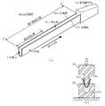
図8は、このような従来の電子楽器の鍵盤装置の内部構造及び質量体を示す構成図である。手前の黒鍵本体部を取り除いて図示している。
図8(a)において、51は白鍵本体部(鍵)、52は黒鍵本体部(鍵)である。フレーム53には、複数の白鍵本体部51、複数の黒鍵本体部52が並設され、それぞれの後端部に回動支点部51a,52aがあり、フレームの鍵支持部53aに支持されている。
In a keyboard apparatus for an electronic musical instrument, a key and a mass body are supported by a frame, and the mass body is rotated in conjunction with a key operation (see Patent Document 1).
FIG. 8 is a block diagram showing the internal structure and mass of such a conventional keyboard device for an electronic musical instrument. The front black key body is removed and shown.
In FIG. 8A, 51 is a white key body (key), and 52 is a black key body (key). The
白鍵本体部51の前方下部から下方に力伝達部51bが突出している。この力伝達部51bの先端は係合片である。この係合片の上下面に弾性部材54が固着されている。白鍵本体部51は、押鍵時に、フレームの前端水平部53bに立設された鍵ガイド53cにより垂直に案内される。
黒鍵本体部52には、図に表れていないが、その前方下部から突出し前方に曲がる力伝達部がある。その先端は対応する質量体に係合する係合片であり、その上下面に弾性部材が固着されている。黒鍵本体部52は、押鍵時に、フレームの中央水平部53dに立設された鍵ガイド(取り除かれた黒鍵本体部に対する鍵ガイド53eと同じもの)により垂直に案内される。
A
Although not shown in the drawing, the black key
一方、55は質量体であり、白鍵本体部51,黒鍵本体部52のそれぞれに対し、ほぼ同様の構造のものが設けられ、それぞれの鍵本体部の下方に配置されている。
56は板バネであって、フレームの貫通窓53fを介して白鍵本体部51の内部と質量体55との間に懸け渡されている。
フレーム53の前方下端位置から後方斜め上方に傾斜板53gが、鍵の配列方向に延設され、その上端部に円柱状の質量体支持部53hが設けられている。質量体55は、質量体支持部53hに回動自在に支持される。
また、傾斜板53gには貫通穴53iが設けられ、貫通穴53iの裏側に設けられたプリント基板57上に2列の鍵スイッチ58が形成されている。
On the other hand, reference numeral 55 denotes a mass body, which has substantially the same structure for each of the white key
A
An
The
図8(b)において、質量体55は、基部3と長尺部材59からなる。基部3には円筒状の回動支点部3aが設けられ、フレーム53側の質量体支持部53hに嵌め込まれる。回動支点部(支点部)3aには突起3bがあり、質量体支持部53hに設けられた溝に嵌め込まれる。
回動支点部3aの前方端には、二股の主被駆動部3c及び副被駆動部3dがあり、両者は、白鍵本体部51側にある力伝達部51bの先端にある係合片に、弾性部材54を介して係合する。黒鍵本体部52の側も同様にして、対応する質量体55と係合する。
In FIG. 8B, the mass body 55 includes a base portion 3 and a
At the front end of the
主被駆動部3c,副被駆動部3dと回動支点部3aとの間の下方には、突状のスイッチ駆動部3eがあり、白鍵本体部51,黒鍵本体部52の前方上面が押鍵されたとき、2列の鍵スイッチ58を、時間差をもって押圧する。
回動支点部3aよりも後方下部に結合部3fがあり、ここにおいて長尺部材59が一体的に結合される。回動支点部3aの外周には、バネ56の係止部3gがある。
長尺部材59は、鍵の長手方向に延在する金属丸棒であり、回動時に大きな慣性モーメントを発生する。回動支点部3aから最も離れた後端部は、折曲延長部59aとなり質量が集中している。
Below the main driven part 3c, the sub driven
There is a connecting
The
図8(a)において、演奏者が白鍵本体部51を押す操作に連動し、質量体55が回動すると、長尺部材59の慣性モーメントに応じた反作用が白鍵本体部51から演奏者の指に与えられる。演奏者が指を鍵から離すと、質量体55は重力の作用により逆回動して図示の位置に戻る。
In FIG. 8A, when the performer presses the white key
フレーム53の後方下部には下限ストッパ(動作規制部材)60が鍵の配列方向に沿って帯状に配置され、後方上部には上限ストッパ(動作規制部材)61が鍵の配列方向に沿って帯状に配置されている。
これらは、通常、フェルトで形成されており、質量体55の回動により、長尺部材59の後端の下部又は折り曲げ延長部59aの上部がフェルトに衝突することにより、質量体55の回動範囲の下限位置及び上限位置を規制する。黒鍵本体部52及びその質量体も同様の動作をする。
A lower limit stopper (operation restricting member) 60 is arranged in a band shape along the key arrangement direction at the lower rear portion of the
These are usually formed of felt. When the mass body 55 rotates, the lower end of the
上述した質量体55の機能は、一般的には、鍵操作した指に質量感を与えることである。しかし、それだけではない。質量体55は、全体的な鍵盤機構の特性を実現するための一部品である。例えば、質量体55を下限ストッパ60、上限ストッパ61に、適度の速度で衝突させることによってストップ感を実現する。
その際、長尺部材59の長さ、剛性、下限ストッパ60,上限ストッパ61(動作規制部材)に当接する当接部(長尺部材59の後端及び折曲延長部59a)の形状、等は、手応えの良好なストップ感を得るために様々な制約を受ける。
The function of the mass body 55 described above is generally to give a sense of mass to a finger operated by a key. But that is not all. The mass body 55 is a component for realizing the characteristics of the entire keyboard mechanism. For example, the stop feeling is realized by causing the mass body 55 to collide with the lower limit stopper 60 and the upper limit stopper 61 at an appropriate speed.
At that time, the length and rigidity of the
とりわけ、電子鍵盤楽器を重くしないために、長尺部材59に金属丸棒を用いることが困難な場合は、長尺部材59の剛性が小さくならないようにする必要がある。剛性が小さいと長尺部材59自身が大きく撓むことにより手応えが悪くなる。そのため、長尺部材59として、中空円断面の管(パイプ)を採用することが考えられる。
薄板板金材を中空円断面のパイプに加工するには、棒状の芯金を用い、これに薄板板金材を長手方向に沿わせて曲げ加工をする。しかし、長いパイプを作ろうとすると、曲げ形成後に芯金を取り出すときの大きな摩擦抵抗により、芯金を抜き出せなかったり、芯金が破断したりする等の問題がある。
In order to process a thin sheet metal material into a pipe having a hollow circular cross section, a rod-shaped core metal is used, and the thin sheet metal material is bent along the longitudinal direction thereof. However, when trying to make a long pipe, there is a problem that the metal core cannot be extracted or the metal core breaks due to a large frictional resistance when the metal core is taken out after bending.
本発明は、上述した問題点を解決するためになされたもので、軽量であっても手応えの良好なストップ感が得られる質量体を備えた電子楽器の鍵盤装置を提供することを目的とするものである。 The present invention has been made to solve the above-described problems, and it is an object of the present invention to provide a keyboard device for an electronic musical instrument having a mass body that can provide a good stop feeling even when lightweight. Is.
本発明は、請求項1に記載の発明においては、電子楽器の鍵盤装置において、複数の鍵と、該各鍵の押鍵操作に連動して回動する複数の各質量体と、前記各鍵及び前記各質量体を支持するフレームと、該フレームの側に配置され前記各質量体の回動範囲を規制する動作規制部材、を有する電子楽器の鍵盤装置において、前記質量体は、長尺部材を有し、該長尺部材は、薄板板金が長手方向に沿って曲げ加工されることにより、開口部を備えた断面を有するものである。
上述した薄板板金とは、整形加工機、折り曲げ加工機等の加工機械により、折り曲げ成型可能な板金材のことである。このような薄板板金材を長尺部材に用いることにより、金属丸棒を用いる場合に比べて質量体を軽量化するとともに、加工性が良くなる。薄板板金材は、平板であったものが曲げ加工されて開口部を備えた断面となることにより、断面2次モーメントを稼ぐことができるため、開口部の方向に、十分な剛性を確保することができる。また、開口部の左右の幅方向にも、ある程度まで剛性を確保することができる。
According to the present invention, in the keyboard device of the electronic musical instrument according to the first aspect, a plurality of keys, a plurality of mass bodies that rotate in conjunction with a key pressing operation of each key, and the keys And a keyboard device for an electronic musical instrument having a frame that supports each mass body and an operation regulating member that is disposed on the frame side and regulates a rotation range of each mass body, wherein the mass body is a long member The long member has a cross section with an opening by bending a thin sheet metal along the longitudinal direction.
The above-described thin sheet metal is a sheet metal material that can be bent and formed by a processing machine such as a shaping machine or a bending machine. By using such a thin sheet metal material for the long member, the mass body is reduced in weight and workability is improved as compared with the case where a metal round bar is used. The thin sheet metal material is obtained by bending a flat plate into a cross section having an opening so that a secondary moment can be obtained. Therefore, sufficient rigidity is ensured in the direction of the opening. Can do. Moreover, rigidity can be ensured to some extent also in the left and right width directions of the opening.
請求項2に記載の発明においては、請求項1に記載の電子楽器の鍵盤装置において、前記長尺部材は、前記長手方向の一部の区間においては、前記開口部が閉じられた断面を有するものである。
長尺部材の開口部が閉じられることにより、大きな断面2次モーメントが得られ、全周囲方向に高剛性の長尺部材が得られる。閉じられた開口部を、溶接等により接合すれば、長尺部材の剛性がさらに高まる。
長尺部材は、その長手方向の一部の区間においてのみ、開口部を閉じていることにより、全区間を閉じた断面とするよりも、曲げ加工が容易となる。開口部は完全に閉じた状態でなくてもよく、僅かな隙間があってもよい。
上述した長手方向の一部の区間を、質量体の回動中心に近い側にすれば、質量体の回動中心に近いために撓みやすい部分の剛性を高めることができる。
質量体の基部を合成樹脂とし、基部を長尺部材と一体化して成形する場合、上述した長手方向の一部の区間を長尺部材の前端側にして、基部をこの長手方向の一部の区間内で一体化する。その際、長手方向の一部の区間の断面を中空円断面にするとよい。
According to a second aspect of the present invention, in the keyboard device for an electronic musical instrument according to the first aspect, the elongate member has a cross section in which the opening is closed in a portion of the longitudinal direction. Is.
By closing the opening of the long member, a large moment of inertia of the cross section is obtained, and a long member having high rigidity in the entire circumferential direction is obtained. If the closed opening is joined by welding or the like, the rigidity of the long member is further increased.
The elongate member is easier to bend than the cross section with the entire section closed by closing the opening only in a part of the section in the longitudinal direction. The opening does not have to be completely closed, and there may be a slight gap.
If the above-described partial section in the longitudinal direction is on the side closer to the rotation center of the mass body, the rigidity of the portion that is easily bent can be increased because it is close to the rotation center of the mass body.
When the base of the mass body is made of synthetic resin and the base is integrated with the long member, the above-mentioned part of the longitudinal direction is the front end side of the long member, and the base is part of this longitudinal direction. Integrate within the section. In that case, it is good to make the cross section of the one part area of a longitudinal direction into a hollow circular cross section.
請求項3に記載の発明においては、請求項1又は2に記載の電子楽器の鍵盤装置において、前記長尺部材は、前記開口部を備えた断面を有する区間において、底部と前記開口部とを備えた断面を有した第1及び第2の部分構造が、相互の前記開口部を上下方向に対向させて、1つの垂直側面部により連結された構造を有するものである。
従って、第1の部分構造、第2の部分構造のいずれか一方のみの場合よりも、長尺部材が撓みにくくなる。
長尺部材の下面部,上面部ともに、底部を備えた断面であるから、下面部,上面部の底部の一部を、そのまま、動作規制部材に衝突する当接部とすることができる。その結果、質量体の構造が簡単になる。底部の一部を当接部とした場合、垂直側面部の高さを変更するだけで、質量体の回動範囲を調節可能であるから、質量体の設計が容易になる。その際、上述した底部の断面形状を、半円又は角丸とすれば、動作規制部材の耐久性が向上する。
According to a third aspect of the present invention, in the keyboard device for an electronic musical instrument according to the first or second aspect, the long member has a bottom portion and the opening portion in a section having a cross section having the opening portion. The first and second partial structures having the provided cross section have a structure in which the openings are opposed to each other in the vertical direction and are connected by one vertical side surface.
Therefore, the long member is less likely to bend than in the case of only one of the first partial structure and the second partial structure.
Since both the bottom surface and the top surface of the long member have a bottom portion, a part of the bottom surface of the bottom surface and the top surface can be used as a contact portion that collides with the operation restricting member as it is. As a result, the structure of the mass body is simplified. When a part of the bottom part is used as the contact part, the rotation range of the mass body can be adjusted only by changing the height of the vertical side surface part, so that the mass body can be easily designed. At this time, if the cross-sectional shape of the bottom portion is a semicircle or a rounded corner, the durability of the operation restricting member is improved.
請求項4に記載の発明においては、請求項1又は2に記載の電子楽器の鍵盤装置において、前記長尺部材は、前記開口部を備えた断面を有する区間の一部である第1の区間においては、底部と前記開口部とを備え、前記開口部が上又は下方向に向いた断面を有した第1の構造であり、前記開口部を備えた断面を有する区間の他の区間である第2の区間においては、前記第1の構造が前記長手方向に延設された第1の部分構造と、底部と前記開口部とを備えた断面を有した第2の部分構造とが、相互の前記開口部を上下方向に対向させて、1つの垂直側面部により連結された構造を有するものである。
従って、第2の区間を質量集中部とすることができる。上述した第2の区間を、質量体の回動中心から遠い側とすれば、長尺部材の質量が同じでも慣性モーメントを大きくすることができる。
上述した第2の区間においては、第1の部分構造、第2の部分構造のいずれか一方のみの場合よりも、長尺部材が撓みにくくなる。
かつ、この第2の区間においては、長尺部材の下面部,上面部ともに、底部を備えた断面となるから、底部の少なくとも一部を、そのまま、動作規制部材に衝突する当接部とすることができる。その結果、質量体の構造が簡単になる。底部の少なくとも一部を当接部とした場合、垂直側面部の高さを変更するだけで、質量体の回動範囲を調節可能であるから、質量体の設計が容易になる。その際、上述した底部の断面形状を、半円又は角丸とすれば、動作規制部材の耐久性が向上する。
According to a fourth aspect of the present invention, in the keyboard device for an electronic musical instrument according to the first or second aspect, the elongated member is a first section that is a part of a section having a cross section having the opening. The first structure having a bottom and the opening, the opening having a cross section facing upward or downward, and another section having a cross section having the opening. In the second section, the first partial structure in which the first structure extends in the longitudinal direction and the second partial structure having a cross section having a bottom portion and the opening portion are mutually connected. These openings are opposed to each other in the vertical direction, and are connected by one vertical side surface.
Therefore, the second section can be a mass concentration part. If the second section described above is on the side far from the rotation center of the mass body, the moment of inertia can be increased even if the mass of the long member is the same.
In the second section described above, the long member is less likely to bend than in the case of only one of the first partial structure and the second partial structure.
And in this 2nd area, since the lower surface part and upper surface part of a long member become a cross section provided with the bottom part, at least one part of a bottom part is made into the contact part which collides with an operation control member as it is. be able to. As a result, the structure of the mass body is simplified. In the case where at least a part of the bottom part is a contact part, the rotation range of the mass body can be adjusted only by changing the height of the vertical side surface part, so that the mass body can be easily designed. At this time, if the cross-sectional shape of the bottom portion is a semicircle or a rounded corner, the durability of the operation regulating member is improved.
請求項5に記載の発明においては、請求項4に記載の電子楽器の鍵盤装置において、前記長尺部材の第2の区間の前記長手方向に沿った長さ、及び、前記長尺部材の前記長手方向に沿った長さの少なくとも一方は、前記質量体の慣性モーメントが、当該長尺部材を有する質量体に対応する鍵の音高又は鍵域に応じた値になるように、当該長尺部材を有する質量体に対応する鍵の音高又は鍵域に応じて異なるものである。
従って、薄板板金材を用いた場合でも、慣性モーメントを異にする質量体を並設することができ、鍵タッチを、鍵の配列方向にスケーリングすることができる。鍵毎に慣性モーメントを変えてもよいが、オクターブ単位など、鍵域毎に慣性モーメントを変えてもよい。
According to a fifth aspect of the present invention, in the keyboard device of the electronic musical instrument according to the fourth aspect, the length of the second section of the long member along the longitudinal direction and the length of the long member At least one of the lengths along the longitudinal direction is such that the moment of inertia of the mass body has a value corresponding to the pitch or key range of the key corresponding to the mass body having the long member. It differs depending on the pitch or key range of the key corresponding to the mass body having the member.
Accordingly, even when thin sheet metal materials are used, mass bodies having different moments of inertia can be arranged side by side, and key touch can be scaled in the key arrangement direction. The moment of inertia may be changed for each key, but the moment of inertia may be changed for each key range, such as an octave unit.
また、本発明は、他の観点から見ると、請求項6に記載の発明のように、複数の鍵と、該各鍵の押鍵操作に連動して支点部を中心に回動する複数の各質量体と、前記各鍵及び前記各質量体を支持するフレームと、該フレームの側に配置され前記各質量体の回動範囲を規制する動作規制部材、を有する電子楽器の鍵盤装置において、前記質量体は、長尺部材を有し、該長尺部材は、長手方向に垂直な断面が中空部と該中空部を規定する外郭を有した形状に形成され、前記断面が長手方向に一様である一様長尺部を有し、前記支点部から遠い位置にある自由端側において前記一様長尺部におけるよりも大きな開口部を有するものである。
長尺部材が、上述した中空部を規定する外郭を有した形状の一様長尺部を有することにより、金属丸棒を用いる場合に比べて質量体を軽量化することができる。
上述した一様長尺部においては、開口部がない(隙間=0)か、又は、開口部となる隙間が小さければ、大きな断面2次モーメントが得られ、全周囲方向に高剛性の長尺部材が得られる。
自由端側においては、一様長尺部における開口部(隙間=0の場合を含む)よりも大きな開口部を有していても、自由端側は撓みにくいのでさほど高い剛性が要求されない。開口部を有していても、平板に比べれば断面2次モーメントを稼ぐことができるため、開口部の方向に、十分な剛性を確保することができる。また、開口部の左右の幅方向にも、ある程度まで剛性を確保することができる。
質量体の基部を合成樹脂とし、基部を長尺部材と一体化して成形する場合、上述した一様長尺部を長尺部材の前端側にして、基部をこの一様長尺部内で一体化する。その際、長手方向の一部の区間の断面を中空円断面にするとよい。
From another point of view, the present invention provides a plurality of keys and a plurality of pivots that rotate about a fulcrum portion in conjunction with a key pressing operation of each key, as in the invention described in claim 6. In a keyboard device for an electronic musical instrument having each mass body, a frame that supports each mass body and each mass body, and an operation regulating member that is disposed on the frame side and regulates the rotation range of each mass body, The mass body has an elongated member, and the elongated member is formed in a shape in which a cross section perpendicular to the longitudinal direction has a hollow portion and an outline defining the hollow portion, and the cross section is uniform in the longitudinal direction. And having a larger opening than that of the uniform long portion on the free end side located far from the fulcrum portion.
When the long member has the uniform long portion having the shape that defines the hollow portion described above, the mass body can be reduced in weight as compared with the case where a metal round bar is used.
In the above-described uniform long portion, if there is no opening (gap = 0), or if the gap serving as the opening is small, a large second moment of section can be obtained, and a highly rigid long portion in the entire circumferential direction. A member is obtained.
On the free end side, even if it has an opening larger than the opening (including the case where the gap = 0) in the uniform long portion, the free end is difficult to bend, and so high rigidity is not required. Even if it has an opening, a cross-sectional secondary moment can be obtained as compared with a flat plate, and therefore sufficient rigidity can be secured in the direction of the opening. Moreover, rigidity can be ensured to some extent also in the left and right width directions of the opening.
When the base of the mass body is made of synthetic resin and the base is integrated with the long member, the above-mentioned uniform long portion is the front end side of the long member, and the base is integrated within the uniform long portion. To do. In that case, it is good to make the cross section of the one part area of a longitudinal direction into a hollow circular cross section.
本願発明によれば、質量体を軽量化しても押鍵時に手応えの良好なストップ感が得られるという効果がある。特に、軽量化が望まれる可搬型の電子楽器に用いる場合に適する。 According to the present invention, even when the mass body is reduced in weight, there is an effect that a good stop feeling can be obtained when pressing the key. In particular, it is suitable for use in a portable electronic musical instrument for which weight reduction is desired.
図1は、本発明の実施形態において用いる質量体の構成図である。
図1(a)において、質量体1は、基部3、長尺部材2、質量集中部4を有し、長尺部材2の前端Fが基部3と一体化され、長尺部材2の後端Bが質量集中部4と一体化され、対応する鍵の押鍵操作に連動して回動する。質量集中部4が、図8に示した下限ストッパ60、上限ストッパ61に衝突する。
基部3は、図8を参照して説明した従来のものを図示しているが、回動支点部3a(支点部)と、鍵側の力伝達部に係合する被駆動部(主被駆動部3c、副被駆動部3d)を有するものであればよい。スイッチ駆動部3eは、基部3の側ではなく、白鍵本体部51、黒鍵本体部52の側に設けられる場合がある。
FIG. 1 is a configuration diagram of a mass body used in an embodiment of the present invention.
In FIG. 1A, the mass body 1 has a base 3, a
Although the base 3 is the same as the conventional one described with reference to FIG. 8, the driven
図1(b)において、長尺部材2は、折り曲げ加工機械により折り曲げ加工が可能な薄板板金から形成される。このような薄板板金が長手方向(長手方向の軸線)に沿って曲げ加工されることにより、長手方向に延在する左端部2a及び右端部2bとの間に、長手方向に沿った開口部2cを備えた断面を有する外郭が形成される。ここで、断面とは、長手方向に垂直となる面で長尺部材2を切断したときの断面である。
長尺部材2は、例えば、長手方向の辺が長い矩形状の薄板板金材に、長手方向に沿って、丸棒状の芯金5を重ね、薄板板金材を長手方向に沿って曲げ加工されることにより形成される。
In FIG.1 (b), the
The
長尺部材2は、長手方向の一部の区間、すなわち、境界位置Pから前端Fまでは、左端部2aと右端部2bとが当接するように、さらに曲げ加工がなされる。
従って、長尺部材2は、後端B近傍(回動支点部3aから遠い位置にある自由端側)において、左端部2aと右端部2bとが平行となって、U字状断面を有する外郭となる。一方、境界位置Pの後端B側近傍では、左端部2aと右端部2bとの間の開口部2cの隙間が徐々に狭まっている。
境界位置Pから前端Fまでの区間においては、開口部2cが閉じられた断面、図示の例では、中空円断面を有した閉曲断面区間(F−P)となる。
The
Therefore, the
In the section from the boundary position P to the front end F, a cross section in which the
この境界位置Pよりもさらに前端F側にある境界位置P’から前端Fまでの区間は、一様長尺部であって、長手方向に垂直な断面が一様であり、この断面は中空部と中空部を規定する外郭とを有した形状になっている。
閉曲断面区間(F−P)において、開口部2cは完全に閉じた状態でなくてもよく、幅方向に僅かな隙間があってもよい。これに関連して、図示の一様長尺部(F−P’)は、開口部がないのである(隙間=0)が、開口部があっても、幅方向の隙間が小さければよい。外郭は、支点部から遠い位置にある自由端側において、この一様長尺部(F−P’)における開口部(隙間=0を含む)よりも大きな開口部2cを有している。
The section from the boundary position P ′ on the front end F side further to the front end F than the boundary position P is a uniform long portion, and the cross section perpendicular to the longitudinal direction is uniform. And an outer shell that defines the hollow portion.
In the closed section (FP), the opening 2c does not have to be completely closed, and there may be a slight gap in the width direction. In this connection, the uniform long portion (FP ′) shown in the figure has no opening (gap = 0), but even if there is an opening, the gap in the width direction may be small. The outer shell has an
前端Fから境界位置Pまでの閉曲断面区間(F−P)は、長尺部材2の一部にすぎない。このため、薄板板金材が芯金5と密着する長さが長尺部材2の長さよりも短くなる。よって、曲げ加工後に芯金5を取り出しやすくなっている。
長尺部材2においては、質量体1の回動支点部(支点部)3aに近いほど撓みやすいから、図示のように、回動支点部3aに近い前端F側を一様長尺部(F−P’)及び閉曲断面区間(F−P)とすればよい。
The closed cross section (FP) from the front end F to the boundary position P is only a part of the
In the
図示の例では、基部3がアウトサート成形されている。長尺部材2の前端Fを金型に差し込んだ状態で、金型の空洞部に合成樹脂を流し込むことにより成形される。従って、前端Fから所定の長さまでが、基部3内に入り込む一体成形区間となる。この一体成形区間は、閉曲断面区間(F−P)内にあるか、さらに、一様長尺部(F−P’)内にある。
従って、基部3を、閉曲断面区間(F−P)内、又は、一様長尺部(F−P’)内で一体化する。
一方、後端Bは、例えば、質量集中部4に溝穴を成形しておき、この溝穴に差し込まれることにより、質量集中部4と一体化される。
なお、長尺部材2と基部3とを一体化するにも、基部3に溝穴を成形しておき、この丸穴に長尺部材2の前端Fを差し込んでもよい。
In the illustrated example, the base 3 is outsert molded. In a state where the front end F of the
Accordingly, the base 3 is integrated in the closed curved section (FP) or in the uniform long section (FP ′).
On the other hand, the rear end B is integrated with the mass concentrating portion 4 by forming a slot in the mass concentrating portion 4 and being inserted into the slot, for example.
In order to integrate the
図1(c)は、前端F付近における長尺部材2の拡大図である。
前端Fに蓋部2dが設けられている。この蓋部2dは、薄板板金材が平板であった元の状態において、左端部2a及び右端部2bを有する矩形平板の前端Fに、連結部2eを介して形成されている。図示の例では、連結部2eの長さの分だけ円板が切り欠かれている。
芯金5を用いて薄板板金材を曲げ加工して閉曲断面を形成した後に、連結部2eの部分で90度折り曲げることにより、前端Fが蓋部2dによって閉じられる。
FIG. 1C is an enlarged view of the
A
After forming the closed cross section by bending the thin sheet metal material using the core metal 5, the front end F is closed by the
上述したアウトサート成形をする際に、一体成形区間では開口部を閉じていることから、長尺部材2は全周囲方向から成型圧力を受ける。その結果、安定した品質の基部が得られる。その際、これらの区間の断面を、特に、中空円断面にすることにより、中空円断面に全周囲方向から均等に成形圧力を受けるから、一層安定した品質の基部3が得られる。
また、一体成形区間では開口部を閉じていることにより、特別な対策をしなくても、溶融状態の合成樹脂が開口部から金型の外部に流出して固化してしまうことがない。流出自体はさほど問題ないが、流出量が一定しないために、製品毎に、質量体1の質量及び慣性モーメントにバラツキが生じるおそれがある。
しかし、閉曲断面であっても、前端Fが開口状態であると、やはり特別な対策をしなければ、溶融状態の合成樹脂が閉曲断面内に流出して固化する。
When performing the above-described outsert molding, since the opening is closed in the integral molding section, the
In addition, since the opening is closed in the integral molding section, the synthetic resin in a molten state does not flow out of the opening and solidify from the opening without special measures. Although there is no problem with the outflow itself, since the outflow amount is not constant, there is a possibility that the mass and the moment of inertia of the mass body 1 vary for each product.
However, even with a closed cross section, if the front end F is in an open state, the synthetic resin in the molten state will flow into the closed cross section and solidify unless special measures are taken.
これに対し、蓋部2dを設ければ、閉曲断面区間(F−P)の前端Fを金型に差し込んでも、溶融した合成樹脂が閉曲断面の中空部内に流出しない。溶融樹脂が流出しなければ、蓋部2dに僅かな隙間があっても構わない。
蓋部2dを設けることに代えて、長尺部材31の中空部の内部に障壁部を設けるようにし、溶融状態の合成樹脂の流出量が一定になるようにすることも可能である。
On the other hand, if the
Instead of providing the
矩形の薄板板金材を曲げ加工すれば、左端部2a及び右端部2bの高さは、閉曲断面区間(F−P)におけるよりも、開口断面区間(P−B)において高くなる。
ただし、薄板板金材が折り曲げられる前の平板であった状態(展開図形の状態)において、閉曲断面区間(F−P)となる左右方向の長さに対し、開口断面区間(P−B)となる左右方向の長さを異ならせて段差をもたせれば、開口断面区間(P−B)における左端部2a,右端部2bの高さを任意に設計できる。
図示の例では、開口部2cが垂直上向きであるが、開口部2cが垂直下向きになるように、長尺部材2を基部3及び質量集中部4と一体化してもよい。
If a rectangular sheet metal material is bent, the heights of the
However, in a state where the thin sheet metal material is a flat plate before being folded (a state of a developed figure), an opening cross-section section (P-B) with respect to a length in the left-right direction that becomes a closed cross-section section (FP). The heights of the
In the illustrated example, the opening 2c is vertically upward, but the
図1(d),図1(e)は、図1に示した長尺部材2の断面形状の説明図である。
図1(d)に示すように、長尺部材2は、閉曲断面区間(F−P)で中空円部とこの中空円部を規定する外郭を有する。中空円断面は薄板板金自体の断面積が小さくても、大きな断面2次モーメント及び断面係数が得られるから、曲げ剛性、曲げ強度が大きくなる。
従って、軽量である割には、大きな曲げ剛性、曲げ強度が得られる。
左端部2aと右端部2bとの当接部は、溶接などで一体化される方が好ましいが、突き合わされているだけであったり、僅かに隙間を残していたりしてもよい。
FIG.1 (d) and FIG.1 (e) are explanatory drawings of the cross-sectional shape of the
As shown in FIG.1 (d), the
Therefore, although it is lightweight, large bending rigidity and bending strength can be obtained.
The contact portion between the
一方、図1(e)に示すように、開口断面区間(P−B)では、境界位置Pの近傍の遷移区間を除いて、外郭は、その左右の側面が、開口部2cを間にして長手方向に沿って平行で垂直に立ち上がった平面であって、その底部が半円の断面であるU字状断面を有する。
図8に示した従来の長尺部材59のように、金属丸棒を用いる場合に比べて、長尺部材2を軽量化できるとともに、断面2次モーメントを大きくすることができ、十分な剛性を確保することができる。
On the other hand, as shown in FIG. 1 (e), in the opening cross-section section (P-B), except for the transition section in the vicinity of the boundary position P, the outer side has the
As in the case of the conventional
開口断面区間(P−B)においては、平板が曲げ加工されて開口部2cを備えた断面となる。これは、水平に配置された単一の平板と比較すれば、垂直方向の断面2次モーメントを稼ぐことができるため、開口部2cの方向(質量体1の回動方向)に、十分な剛性を確保することができる。
図1(e)に示した開口断面区間(P−B)においては、図1(d)に比べて、垂直方向(質量体1の回動方向)に外郭が高くなった分だけ、垂直方向の断面2次モーメントを稼いでいる。
また、垂直に配置された単一の平板と比較すれば、開口部2cの左右の幅方向(鍵の配列方向)にも、ある程度までの剛性を確保することができる。
特に、図1(b)に示したように、後端Bが質量集中部4と一体化されている場合、開口断面区間(P−B)においても、開口部2cの左右の幅方向の撓みに強くなる。
In the opening cross section (P-B), the flat plate is bent to form a cross section having the
In the opening cross section (P-B) shown in FIG. 1 (e), the vertical direction is the same as the height of the outline in the vertical direction (rotating direction of the mass body 1) compared to FIG. 1 (d). The second moment of the section is earned.
Further, as compared with a single flat plate arranged vertically, a certain degree of rigidity can be ensured also in the left and right width direction (key arrangement direction) of the
In particular, as shown in FIG. 1B, when the rear end B is integrated with the mass concentration portion 4, the left and right lateral deflections of the
図1に示した、長尺部材2の断面は、閉曲断面、開口断面を有していれば、曲げ加工により、軽量である割には大きな曲げ剛性、曲げ強度が得られる。従って、必ずしも中空円断面、U字状断面でなくてもよい。
図2は、図1に示した長尺部材2の他の具体例を示す説明図である。
図2(a),図2(b)に示すように、図2(b)では、薄板板金材が長手方向に沿って、例えば、角丸の矩形芯金を用いて、角を丸くした曲げ加工がなされ、左端部11aと右端11bとが上に開口し、角丸の底部11dと開口部11cを備えた断面を有する長尺部材11が形成される。外郭の左右の側面は、開口部11cを間にして長手方向に沿って平行で垂直に立ち上がった平面となる。
図2(a)では、薄板板金材が長手方向に沿って、さらに引き続き、角を丸くした曲げ加工がなされた結果、左端部11aと右端部11bとが当接して断面が閉じ、角丸の中空矩形断面となる。
As long as the cross section of the
FIG. 2 is an explanatory view showing another specific example of the
As shown in FIGS. 2 (a) and 2 (b), in FIG. 2 (b), the sheet metal material is bent along the longitudinal direction using, for example, rounded rectangular metal cores, with rounded corners. The
In FIG. 2 (a), as a result of the sheet metal sheet being further bent along the longitudinal direction with rounded corners, the
図示を省略するが、薄板板金材が長手方向に沿って、矩形芯金を用いて曲げ加工がなされてもよい。この場合、図2(b)において、角が丸められていない底部を備えた凹部断面が得られ、図2(a)において、角が丸められていない中空四角形状の断面が得られる。
また、図2(c)、図2(d)に示すように、図2(c)の閉曲断面区間においては、左端部12aと右端部12bとが当接して断面が閉じているから、図1(d)と同様の中空円断面である。
図2(d)の開口断面区間では、左端部12cと右端部12dとの間に開口部12eを備えるが、左右側面部が除かれた半円の底部のみを有する断面となっている。
この例では、薄板板金材が折り曲げられる前の平板であった状態(展開図形の状態)において、閉曲断面区間(F−P)となる薄板板金の左右方向の長さに対し、開口断面区間(P−B)となる左右方向の長さを短くしてある。
Although illustration is omitted, the thin metal plate may be bent along the longitudinal direction using a rectangular metal core. In this case, in FIG. 2B, a concave cross section having a bottom portion with no rounded corners is obtained, and in FIG. 2A, a hollow quadrangular cross section with no rounded corners is obtained.
Further, as shown in FIGS. 2C and 2D, in the closed cross section of FIG. 2C, the
In the opening cross-section section of FIG. 2D, the
In this example, in a state where the thin sheet metal material is a flat plate before being folded (a state of a developed figure), an opening cross-section section with respect to the length in the left-right direction of the thin sheet metal that becomes a closed section section (FP) The length in the left-right direction that becomes (P-B) is shortened.
図3は、本発明の第2の実施形態において用いる質量体の部分構成図である。
質量体の基部については、図示を省略するが、図1を参照して説明した実施形態の基部3と同様のものを用いればよい。
この実施の形態は、図1に示した実施の形態において、前端Fから後端Bまで、長尺部材2の全長が開口断面区間(F−B)の外郭を有するものである。
図3(a)に示すように、矩形状の薄板板金材が長手方向に沿って曲げ加工されることにより、長尺部材21は、長手方向に延在する左端部21a及び右端部21bとの間に、長手方向に沿った開口部21cを備えた断面を有する。従って、開口部21cの方向(質量体の回動方向)に断面2次モーメントを稼ぐことができる。
FIG. 3 is a partial configuration diagram of a mass body used in the second embodiment of the present invention.
Although the illustration of the base of the mass body is omitted, the same base as the base 3 of the embodiment described with reference to FIG. 1 may be used.
In this embodiment, in the embodiment shown in FIG. 1, the entire length of the
As shown in FIG. 3A, the
図示の例では、左右の側面が、図1(e)に示したものと同様のU字状断面となる。これに代えて、長尺部材21は、図2(b),図2(d)に示したものと同様の、開口断面形状を有したものでもよい。
長尺部材21の後端Bは質量集中部22と一体化され、前端Fは、アウトサート成形等により基部3と一体化される。
そのため、長尺部材21が全長にわたって開口断面区間(F−B)になっていても、横方向(鍵の配列方向)の撓みに強くなる。
In the illustrated example, the left and right side surfaces have a U-shaped cross section similar to that shown in FIG. Instead, the
The rear end B of the
Therefore, even if the
図3(b)に示すように、U字状の凹部23aを有する下金型23と、U字状の凸部24aを有する上金型24との間に、平板状の薄板板金21’を置いてプレスすることにより、上下型で曲げ加工をすることにより、長尺部材21が得られる。図1に示した芯金5を必要としないから、薄板板金の曲げ加工がさらに簡単になる。
図示の例では、開口断面区間(F−B)において、開口部21cが上向きであるが、開口部21cが下向きになるようにしてもよい。
As shown in FIG. 3B, a
In the illustrated example, the opening 21c is upward in the opening cross section (FB), but the opening 21c may be downward.
図4は、本発明の第3の実施形態において用いる質量体の部分構成図である。
質量体の基部については、図示を省略するが、図1を参照して説明した実施形態の基部3と同様のものを用いればよい。質量集中部は、後端Bに設けてもよいし、設けなくてもよい。
図4(a)において、31は長尺部材であって、前端Fから後端Bまでの全区間が開口断面区間(F−B)であって、外郭は、長手方向に延在する第1の右端部31a及び第2の右端部31dを有し、両者の間に、長手方向に沿った開口部(以後、第3の開口部31hという)を有する。
この第3の開口部31hは、右向きであるが、第3の開口部が左向きであれば、第1の右端部31aと第2の右端部31dに代えて、第1の左端部及び第2の左端部を有することとなる。
FIG. 4 is a partial configuration diagram of a mass body used in the third embodiment of the present invention.
Although the illustration of the base of the mass body is omitted, the same base as the base 3 of the embodiment described with reference to FIG. 1 may be used. The mass concentration portion may be provided at the rear end B or may not be provided.
In FIG. 4 (a), 31 is a long member, the entire section from the front end F to the rear end B is an opening cross section section (F-B), and the outer shell is a first extending in the longitudinal direction.
The
図4(b)は、長手方向に垂直な平面で長尺部材31を切った断面図である。長尺部材31を、第1及び第2の部分構造が連結された構造として説明する。
第1の部分構造は、第1の底部31cと第1の開口部31bを備え、半円の底部と開口部とを備えた断面を有する。
第2の部分構造は、第2の底部31fと第2の開口部31eを備え、半円の底部と開口部とを備えた断面を有する。
図示の、第1,第2の部分構造は、その左右の側面が、第1の開口部31b,第2の開口部31eを間にして長手方向に沿って平行で垂直に立ち上がった平面であって、両平面を結合する第1の底部31c,第2の底部31fが半円の断面であるから、上下に位置して対向する1対のU字形断面を有する。
これらの第1及び第2の部分構造は、相互の開口部31b,31eが上下方向に対向し、図示の例では、その左側を、垂直側面部31gにより連結される。
FIG. 4B is a cross-sectional view of the long member 31 cut along a plane perpendicular to the longitudinal direction. The long member 31 will be described as a structure in which the first and second partial structures are connected.
The first partial structure includes a
The second partial structure includes a
The left and right side surfaces of the first and second partial structures shown in the figure are planes that rise in parallel and vertically along the longitudinal direction with the first opening 31b and the second opening 31e in between. Since the
In these first and second partial structures, the openings 31b and 31e are opposed to each other in the vertical direction, and in the illustrated example, the left side thereof is connected by a vertical
先に、図3を参照して説明した実施形態は、長尺部材21が第1の部分構造のみを備えたものとみることができる。これに対し、図4に示す実施の形態では、第2の部分構造が連結された構造であるから、長尺部材31が撓みにくくなる。
図示の例では、第1,第2の部分構造が、図1(e)に示したU字形断面を有している。しかし、図2(b)に示した長尺部材11と同様な、角丸の底部を有した断面、図2(d)に示した長尺部材12と同様な、半円の断面を有していてもよい。
第1,第2の部分構造がU字形断面を有している場合、第1,第2の部分構造に含まれる左側の垂直側面部分は、上述した垂直側面部31gと一体の垂直平面となっている。
The embodiment described above with reference to FIG. 3 can be regarded as the
In the illustrated example, the first and second partial structures have the U-shaped cross section shown in FIG. However, similar to the
When the first and second partial structures have a U-shaped cross section, the left vertical side surface portion included in the first and second partial structures is a vertical plane integrated with the above-described vertical
後端Bに図1に示したような質量集中部4を設けない場合、第1の底部31c,第2の底部31fの一部である、長尺部材31の後端Bの近傍が、図8に示した下限ストッパ60,上限ストッパ61に衝突する当接部となる。長尺部材31は、第1の底部31c,第2の底部31fともに、半円又は角丸の底を備えた断面を有するから、底部の断面形状が尖っている場合よりも、経年変化により、下限ストッパ60,上限ストッパ61(動作規制部材)が沈み込んだままになったり、切断したりすることが少なくなるから、動作規制部材の耐久性が向上する。
図示の例では、全長にわたって開口断面区間(F−B)であるが、図1の実施形態と同様に、前端F側に閉曲断面区間(F−P)を設けてもよい。
When the mass concentration portion 4 as shown in FIG. 1 is not provided at the rear end B, the vicinity of the rear end B of the long member 31 that is a part of the
In the example shown in the drawing, the opening section section (F-B) extends over the entire length, but a closed section section (FP) may be provided on the front end F side as in the embodiment of FIG.
図4(a)において、31iは貫通穴であり、31jは小突起である。図4(b)に示す垂直側面部(第1,第2の部分構造に含まれる左側の垂直側面部分及び垂直側面部31g)において、その後端B近傍に貫通穴31iが設けられ、その後端Bに小突起31jが設けられている。
これらの貫通穴31i又は小突起31jは必須ではないが、長尺部材31の質量調節、アウトサート成形時の固定位置決めに用いることができる。貫通穴31iは、メッキ装置や部品自動搬送装置における長尺部材31の保持運搬にも用いることができる。
また、図8を参照して後述する鍵タッチ・スケーリングのように、長尺部材31に種々の変形体(バリエーション)がある場合に、貫通穴31iの大きさ,位置、小突起31jの大きさ,位置を変形体に応じて変えることにより、変形体の自動認識、選別といった、生産管理に用いることができる。
In FIG. 4A, 31i is a through hole and 31j is a small protrusion. In the vertical side surface portion (left vertical side surface portion and vertical
These through holes 31i or
In addition, as in the case of key touch scaling described later with reference to FIG. 8, when the elongated member 31 has various deformation bodies (variations), the size and position of the through hole 31i, and the size of the
図5は、本発明の第4の実施形態において用いる質量体の部分構成図である。
質量体の基部については、図示を省略するが、図1を参照して説明した実施形態の基部3と同様のものを用いればよい。
この実施の形態の長尺部材41は、左側面において、長手方向に沿って、明確な段差(段差位置X)を有している。前端Fから境界位置Pまでは閉曲断面区間(F−P)、境界位置Pから段差位置Xまでは第1の開口断面区間(P−X)、段差位置Xから後端Bまでは第2の開口断面区間(X−B)である。
FIG. 5 is a partial configuration diagram of a mass body used in the fourth embodiment of the present invention.
Although the illustration of the base of the mass body is omitted, the same base as the base 3 of the embodiment described with reference to FIG. 1 may be used.
The long member 41 of this embodiment has a clear step (step position X) along the longitudinal direction on the left side. A closed section (FP) from the front end F to the boundary position P, a first opening section (PX) from the boundary position P to the step position X, and a second from the step position X to the rear end B. It is an opening cross-section area (XB).
閉曲断面区間(F−P)と第1の開口断面区間(P−X)とを合わせた区間は、図1に示した実施形態の長尺部材2に対応する。
すなわち、長尺部材41は、閉曲断面区間(F−P)においては、左端部41aと右端部41bとの間の開口部41cが閉じられた断面(図1と同様に、完全に閉じられていなくてもよい)、図示の例では、中空円断面を有する。
長尺部材41は、第1の開口断面区間(P−X)においては、平板状の薄板板金が長手方向に沿って曲げ加工される。その結果、外郭は、長手方向に延在する左端部41a及び第1の右端部41bとの間に、長手方向に沿って半円の第1の底部と開口部41cを備えたU字状断面の第1の構造を有している。
A section obtained by combining the closed curved section (FP) and the first opening section (PX) corresponds to the
That is, the long member 41 is completely closed in the closed section (FP) in which the
In the long member 41, a flat sheet metal plate is bent along the longitudinal direction in the first opening cross section (PX). As a result, the outer shell has a U-shaped cross section provided with a semicircular first bottom and an
長尺部材41は、第2の開口断面区間(X−B)においては、上述した第1の開口断面区間(P−X)の曲げ加工に加えて、さらに、左側の垂直側面部41hが上部において長手方向(長手方向の軸)に沿って曲げ加工される。その結果、外郭は、第2の右端部41eにより第2の開口部41fが形成されることにより、図4に示した長尺部材31と同様の断面構造を有し、第1の右端部41bと第2の右端部41eとの間に、長手方向に沿った開口部(第3の開口部41i)を有する。
この第3の開口部41iは、右向きであるが、第3の開口部が左向きであれば、第1の右端部41bと第2の右端部41eに代えて、第1の左端部及び第2の左端部を有することとなる。
In the long opening member 41, in the second opening section (X-B), in addition to the bending process of the first opening section (PX) described above, the left vertical
The third opening 41i is facing right. However, if the third opening is facing left, the first left end and the second
第2の開口断面区間(X−B)における長尺部材41を、図4(b)と同様に、3つの部分構造が連結された構造として説明する。
第1の開口断面区間(P−X)における第1の構造が長手方向に延設された第1の部分構造と、半円の底部41g(図4(b)の31fに相当)と第2の開口部41f(図4(b)の31eに相当)を備えた断面を有した第2の部分構造とが、相互の開口部41c,41f(図4(b)の31b,31eに相当)を上下方向に対向させて、左側の1つの垂直側面部41h(図4(b)の31gに相当)により連結された構造を有する。
The long member 41 in the second opening cross section (X-B) will be described as a structure in which three partial structures are connected, as in FIG.
The first partial structure in which the first structure in the first opening cross section (PX) extends in the longitudinal direction, the
長尺部材41の第1の開口断面区間(P−X)における断面構造は、図2(d)に示した半丸の断面を有するものであってもよい。また、長尺部材41の閉曲断面区間(F−P)における断面構造は、図2(a)に示した角丸の底面を有し、長尺部材41の第1の開口断面区間(P−X)における断面構造は、図2(b)に示した角丸の底部を有するものであってもよい。
開口断面区間の後方部分である第2の開口断面区間(X−B)における、第1の底部41d,第2の底部41gの少なくとも一部は、下限ストッパ60,上限ストッパ61という動作規制部材に当接する部分でもある。第1の底部41dと第2の底部41gとは、半円又は角丸の底部となっているので、図4を参照して説明したように、下限ストッパ60,上限ストッパ61(動作規制部材)の耐久性が向上する。
なお、41jは図1に示した蓋部2dと同じものであり、41kは図1に示した連結部2eと同じものであり、説明を省略する。
The cross-sectional structure in the first opening cross section (PX) of the long member 41 may have a semicircular cross section shown in FIG. The cross-sectional structure of the long member 41 in the closed cross section (FP) has a rounded bottom surface shown in FIG. 2A, and the first open cross section (P The cross-sectional structure in -X) may have a rounded bottom as shown in FIG.
At least a part of the
41j is the same as the
第2の開口断面区間(X−B)は、閉曲断面区間(F−P)や第1の開放断面区間(P−X)に比べて、質量が集中しているから質量集中部となる。従って、図1に示したような別部材としての質量集中部4に代えて、板金加工だけで質量集中部を形成できる。この場合、後端Bが自由端部になる。
慣性モーメントは、質量と回転半径の2乗とに比例するから、開口断面区間の後方部分である第2の開口断面区間(X−B)を質量集中部とすることにより、慣性モーメント又は慣性質量が大きくなる。
The second open cross section (X-B) is a mass concentration portion because the mass is concentrated compared to the closed curved cross section (FP) and the first open cross section (PX). . Therefore, instead of the mass concentration portion 4 as a separate member as shown in FIG. 1, the mass concentration portion can be formed only by sheet metal processing. In this case, the rear end B becomes a free end.
Since the moment of inertia is proportional to the mass and the square of the radius of rotation, the moment of inertia or the inertial mass can be obtained by using the second aperture cross section (X-B), which is the rear portion of the aperture cross section, as the mass concentration portion. Becomes larger.
図示の例では、垂直側面部41hは左側面であるが、右側面であってもよい。また、第2の開口断面区間(X−B)において、第1の右端部41bも高くすることにより、左右側面部を共に、第1の開口断面区間(P−X)から段差を設けて高くしてもよい。この場合、一方の側面は曲げ加工し、他方の側面は曲げ加工しないで平面のままとし、一方の曲げ加工された端部と他方の曲げ加工されない端部とが第3の開口部41iを間にして対向するか又は接合するようにすればよい。
図示の例では、図1の実施形態と同様に、長尺部材41に閉曲断面区間(F−P)を設けているが、全長が開口断面区間、すなわち、第1の開口断面区間(F−X)+第2の開口断面区間(X−B)であってもよい。
In the illustrated example, the vertical
In the illustrated example, as in the embodiment of FIG. 1, the long member 41 is provided with a closed cross section (FP), but the entire length is an open cross section, that is, a first open cross section (F). -X) + second opening cross section (X-B).
図5においても、先に示した図4(a)と同様に、貫通穴41l、小突起41mが設けられている。第2の開口断面区間(質量集中部)(X−B)における垂直側面部(第1,第2の部分構造に含まれる左側の垂直側面部分及び垂直側面部41h)の後端B近傍に貫通穴41lが設けられ、その後端Bに小突起41mが設けられている。
これらの貫通穴41l又は小突起41mもまた必須のものではないが、図4(a)に示した貫通穴31i、小突起31jと同様の用途に用いることができる。
Also in FIG. 5, a through hole 41l and a
These through holes 41l or
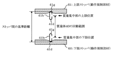
図6は、図5に示した実施形態の質量体40を採用した電子楽器の鍵盤構造を示す構成図である。
図中、図8,図5と同様な部分には同じ符号を付して説明を省略する。
また、図7は、図6に示した鍵盤装置における質量体40の動作を説明する模式図である。
質量体40における質量集中部の下限位置において、長尺部材41の第1の底部41gが制動され、下限ストッパ60を僅かに押し下げた状態で静止している。一方、質量集中部の上限位置において、長尺部材41の第2の底部41gが上限ストッパ61を押し上げて制動される。
FIG. 6 is a block diagram showing a keyboard structure of an electronic musical instrument that employs the mass body 40 of the embodiment shown in FIG.
In the figure, the same parts as those in FIGS.
FIG. 7 is a schematic diagram for explaining the operation of the mass body 40 in the keyboard apparatus shown in FIG.
At the lower limit position of the mass concentration portion in the mass body 40, the
質量集中部の下限位置における長尺部材41の第1の底部41dの位置と、質量集中部の上限位置における長尺部材41の第2の底部41gの位置との差が、ストッパ間の基準距離となり、フレーム53側の構造及び下限ストッパ60、上限ストッパ61の構造により決まる。
これに対し、質量体40の回動範囲(ストローク)は、下限位置にある質量集中部の中心と上限位置にある質量集中部の中心間の距離となる。
従って、質量集中部、すなわち、第2の開口断面区間(X−B)における垂直側面部41hの高さを設計変更するだけで、質量体40の回動範囲を調整することができ、質量体40の回動範囲をストッパ間の基準距離に適したものにすることができる。
The difference between the position of the
On the other hand, the rotation range (stroke) of the mass body 40 is the distance between the center of the mass concentrated portion at the lower limit position and the center of the mass concentrated portion at the upper limit position.
Accordingly, the rotational range of the mass body 40 can be adjusted by simply changing the design of the height of the mass concentration portion, that is, the vertical
また、従来、質量体の慣性モーメントを、鍵に割り当てられた音高又は鍵域(音域)に応じて異ならせるという鍵タッチ・スケーリングが行われている。例えば、高音鍵になるにつれて質量体の質量を軽くすることにより、低音鍵に対しては重みのある鍵タッチで演奏でき、高音鍵になるに従って軽い鍵タッチで演奏できるようにしている。
図1,図3に示した実施の形態では、質量集中部3,22の質量を変える。
これに対し、図5に示した実施の形態では、段差位置Xを変えることにより、第2の開口断面区間(X−B)の、長手方向に沿った長さを、質量体30の慣性モーメントが、長尺部材31を有する質量体30に対応する鍵に割り当てられた音高又は鍵域に応じた値になるように、異ならせればよい。それに応じて、長尺部材41の慣性モーメントも変化するから、簡単に、鍵の音高又は鍵域に応じて鍵タッチ感を異ならせることができる。
典型的には、高音鍵になるほど、又は、高音鍵域になるほど、段差位置Xを長手方向後方になるように、薄板板金材の平面展開形状を設計すればよい。
Conventionally, key touch scaling has been performed in which the moment of inertia of the mass body is made different according to the pitch or key range (sound range) assigned to the key. For example, by reducing the mass of the mass body as it becomes a high tone key, a bass key can be played with a heavy key touch, and as a treble key is played, it can be played with a light key touch.
In the embodiment shown in FIGS. 1 and 3, the masses of the mass concentrating parts 3 and 22 are changed.
On the other hand, in the embodiment shown in FIG. 5, by changing the step position X, the length along the longitudinal direction of the second opening cross section (XB) is changed to the moment of inertia of the
Typically, the planar developed shape of the thin sheet metal material may be designed so that the step position X becomes rearward in the longitudinal direction as the pitch is higher or the range is higher.
一方、前端F−後端B間の長さ(長尺部材41の長手方向の長さ)を、この質量体40に対応する鍵に割り当てられた音高又は鍵域に応じて異ならせることによっても、質量体40の慣性モーメントが、この質量体40に対応する鍵の音高又は鍵域に応じた値になるようにすることができる。
例えば、第2の開口断面区間(X−B)の長さ(質量集中部の長さ)を一定にしておき、高音鍵、又は、高音鍵域になるほど、前端F−後端B間の長さを短くすればよい。
この方法は、図4を参照して説明した実施形態にも適用できる。
ただし、長尺部材31自体の長さを変える場合は、図6に示した鍵盤構造においては、質量体の回動範囲が変化してしまい、かつ、下限ストッパ60、上限ストッパ61との当接位置が鍵盤の奥行き方向に変化してしまうという問題がある。
また、長尺部材31自体の長さと質量集中部の長さとを同時に変更する方法もある。
On the other hand, by varying the length between the front end F and the rear end B (the length in the longitudinal direction of the long member 41) according to the pitch or key range assigned to the key corresponding to the mass body 40. In addition, the moment of inertia of the mass body 40 can be set to a value corresponding to the pitch or key range of the key corresponding to the mass body 40.
For example, the length of the second opening cross section (X-B) (the length of the mass concentrating portion) is kept constant, and the length between the front end F and the rear end B becomes higher as the pitch key or the treble key range is reached. You can shorten it.
This method can also be applied to the embodiment described with reference to FIG.
However, when the length of the long member 31 itself is changed, in the keyboard structure shown in FIG. 6, the rotation range of the mass body is changed, and the
There is also a method of simultaneously changing the length of the long member 31 itself and the length of the mass concentration portion.
また、図4を参照して説明した貫通穴31i、小突起31j、図5を参照して説明した貫通穴41l、小突起41mは、単なる質量調整ではなく、鍵タッチ・スケーリングのために用いることもできる。
図5を参照して説明する。貫通穴41l及び小突起41mの少なくとも一方の大きさ及び又は位置を、長尺部材41を有する質量体に対応する鍵の音高又は鍵域に応じて異なるようにして、質量体の慣性モーメントが、長尺部材41を有する質量体に対応する鍵の音高又は鍵域に応じた値になるようにする。
先に説明した、長尺部材41の第2の開口断面区間(X−B)の長さ、及び、前端F−後端B間の長さの少なくとも一方を異ならせることと併用してもよい。
Further, the through hole 31i and the
This will be described with reference to FIG. The size and / or position of at least one of the through hole 41l and the
You may use together with making at least one of the length of the 2nd opening cross-section area (XB) of the elongate member 41 demonstrated previously, and the length between the front end F-rear end B different. .
1,40,55…質量体、2,11,12,21,21’,31,41,59…長尺部材、
2a,11a,12a,12c,21a,41a…左端部、2b,11b,12b,12d,21b…右端部、31a,41b…第1の右端部、31e,41e…第2の右端部、2c,11c,12e,21c,…開口部、31b,41c…第1の開口部、31e,41f…第2の開口部、2d,41j…蓋部、2e,41k…連結部、11d…底部、31c,41d…第1の底部、31f,41g…第2の底部、31g,41h…垂直側面部、31h,41i…第3の開口部、31i,41l…貫通穴、31j,41m…小突起、
F…前端、P,P’…境界位置、X…段差位置、B…後端、
F−P’…一様長尺部、F−P…閉曲断面区間(長手方向の一部の区間)、P−B…開口断面区間(開口部を備えた断面を有する区間)、P−X…第1の開口断面区間(第1の区間)、X−B…第2の開口断面区間(第2の区間)、
3…基部、3a…回動支点部(支点部)、3b…突起、3c…主被駆動部、3d…副被駆動部、3e…スイッチ駆動部、3f…結合部、3g…板バネの係止部、
4…質量集中部、5…芯金、
51…白鍵本体部(鍵)、52…黒鍵本体部(鍵)、53…フレーム、56…板バネ、59…長尺部材、59a…折曲延長部、60…下限ストッパ(動作規制部材)、61…上限ストッパ(動作規制部材)
1, 40, 55 ... mass body, 2, 11, 12, 21, 21 ', 31, 41, 59 ... long member,
2a, 11a, 12a, 12c, 21a, 41a ... left end, 2b, 11b, 12b, 12d, 21b ... right end, 31a, 41b ... first right end, 31e, 41e ... second right end, 2c, 11c, 12e, 21c, ... opening, 31b, 41c ... first opening, 31e, 41f ... second opening, 2d, 41j ... lid, 2e, 41k ... connection, 11d ... bottom, 31c, 41d ... 1st bottom part, 31f, 41g ... 2nd bottom part, 31g, 41h ... Vertical side part, 31h, 41i ... 3rd opening part, 31i, 41l ... Through-hole, 31j, 41m ... Small protrusion,
F: front end, P, P '... boundary position, X ... step position, B ... rear end,
FP '... uniform long part, FP ... closed curved section (part in the longitudinal direction), PB ... open section (section having a section with an opening), P- X ... 1st opening cross-section area (1st area), XB ... 2nd opening cross-section area (2nd area),
3 ... Base part, 3a ... Rotating fulcrum part (fulcrum part), 3b ... Projection, 3c ... Main driven part, 3d ... Sub driven part, 3e ... Switch drive part, 3f ... Coupling part, 3g ... Coupling of leaf spring Stop,
4 ... mass concentration part, 5 ... cored bar,
DESCRIPTION OF
Claims (6)
前記質量体は、長尺部材を有し、
該長尺部材は、薄板板金が長手方向に沿って曲げ加工されることにより、開口部を備えた断面を有するものである、
ことを特徴とする電子楽器の鍵盤装置。 A plurality of keys, a plurality of mass bodies that rotate in conjunction with a key pressing operation of each key, a frame that supports each key and each mass body, and each mass that is disposed on the frame side In a keyboard device for an electronic musical instrument having an operation restricting member that restricts a rotation range of the body,
The mass body has a long member,
The long member has a cross section with an opening by bending a thin sheet metal along the longitudinal direction.
A keyboard device for an electronic musical instrument.
ことを特徴とする請求項1に記載の電子楽器の鍵盤装置。 The long member has a cross section in which the opening is closed in a portion of the longitudinal direction.
The keyboard device for an electronic musical instrument according to claim 1.
ことを特徴とする請求項1又は2に記載の電子楽器の鍵盤装置。 In the section having a cross section with the opening, the elongate member has a first section and a second partial structure having a cross section with the bottom and the opening. It has a structure that is opposed and connected by one vertical side surface part,
The keyboard device for an electronic musical instrument according to claim 1, wherein the keyboard device is an electronic musical instrument.
前記開口部を備えた断面を有する区間の一部である第1の区間においては、底部と前記開口部とを備え、前記開口部が上又は下方向に向いた断面を有した第1の構造であり、
前記開口部を備えた断面を有する区間の他の区間である第2の区間においては、前記第1の構造が前記長手方向に延設された第1の部分構造と、底部と前記開口部とを備えた断面を有した第2の部分構造とが、相互の前記開口部を上下方向に対向させて、1つの垂直側面部により連結された構造を有するものである、
ことを特徴とする請求項1又は2に記載の電子楽器の鍵盤装置。 The long member is
In a first section which is a part of a section having a section with the opening, a first structure having a bottom and the opening, the opening having a section facing upward or downward. And
In a second section, which is another section having a section with the opening, the first partial structure in which the first structure extends in the longitudinal direction, a bottom, and the opening And a second partial structure having a cross-section having a structure in which the openings are connected to each other in a vertical direction with the openings facing each other in the vertical direction.
The keyboard device for an electronic musical instrument according to claim 1, wherein the keyboard device is an electronic musical instrument.
ことを特徴とする請求項4に記載の電子楽器の鍵盤装置。 At least one of the length along the longitudinal direction of the second section of the long member and the length along the longitudinal direction of the long member is the moment of inertia of the mass body, It differs depending on the pitch or key range of the key corresponding to the mass body having the long member so that the value corresponds to the pitch or key range of the key corresponding to the mass body having the member.
The keyboard device for an electronic musical instrument according to claim 4.
前記質量体は、長尺部材を有し、
該長尺部材は、長手方向に垂直な断面が中空部と該中空部を規定する外郭を有した形状に形成され、前記断面が長手方向に一様である一様長尺部を有し、前記支点部から遠い位置にある自由端側において前記一様長尺部におけるよりも大きな開口部を有する、
ことを特徴とする電子楽器の鍵盤装置。 A plurality of keys, a plurality of mass bodies that rotate about a fulcrum portion in conjunction with a key pressing operation of the keys, a frame that supports the keys and the mass bodies, and a side of the frame In a keyboard device for an electronic musical instrument having an operation restricting member that is disposed and restricts a rotation range of each mass body,
The mass body has a long member,
The elongate member is formed in a shape in which a cross section perpendicular to the longitudinal direction has a hollow portion and an outer shell defining the hollow portion, and the cross section has a uniform long portion that is uniform in the longitudinal direction, Having a larger opening at the free end located far from the fulcrum than at the uniform length,
A keyboard device for an electronic musical instrument.
Priority Applications (4)
| Application Number | Priority Date | Filing Date | Title |
|---|---|---|---|
| JP2007140369A JP4946629B2 (en) | 2007-05-28 | 2007-05-28 | Electronic musical instrument keyboard device |
| EP08104048A EP1998318B1 (en) | 2007-05-28 | 2008-05-21 | Electronic musical instrument keyboard apparatus |
| US12/125,349 US7858863B2 (en) | 2007-05-28 | 2008-05-22 | Electronic musical instrument keyboard apparatus |
| CN2008100989935A CN101315767B (en) | 2007-05-28 | 2008-05-26 | Electronic musical instrument keyboard apparatus |
Applications Claiming Priority (1)
| Application Number | Priority Date | Filing Date | Title |
|---|---|---|---|
| JP2007140369A JP4946629B2 (en) | 2007-05-28 | 2007-05-28 | Electronic musical instrument keyboard device |
Publications (2)
| Publication Number | Publication Date |
|---|---|
| JP2008292914A JP2008292914A (en) | 2008-12-04 |
| JP4946629B2 true JP4946629B2 (en) | 2012-06-06 |
Family
ID=39587943
Family Applications (1)
| Application Number | Title | Priority Date | Filing Date |
|---|---|---|---|
| JP2007140369A Expired - Fee Related JP4946629B2 (en) | 2007-05-28 | 2007-05-28 | Electronic musical instrument keyboard device |
Country Status (4)
| Country | Link |
|---|---|
| US (1) | US7858863B2 (en) |
| EP (1) | EP1998318B1 (en) |
| JP (1) | JP4946629B2 (en) |
| CN (1) | CN101315767B (en) |
Families Citing this family (6)
| Publication number | Priority date | Publication date | Assignee | Title |
|---|---|---|---|---|
| JP4946629B2 (en) * | 2007-05-28 | 2012-06-06 | ヤマハ株式会社 | Electronic musical instrument keyboard device |
| JP5962049B2 (en) | 2012-02-15 | 2016-08-03 | ヤマハ株式会社 | Electronic musical instrument keyboard device |
| JP5962048B2 (en) | 2012-02-15 | 2016-08-03 | ヤマハ株式会社 | Electronic musical instrument keyboard device |
| JP2018156039A (en) * | 2017-03-21 | 2018-10-04 | カシオ計算機株式会社 | Hammer unit and keyboard device |
| DE102018203863A1 (en) * | 2017-03-21 | 2018-09-27 | Kabushiki Kaisha Kawai Gakki Seisakusho | Hammer device and keyboard device for an electronic keyboard instrument |
| WO2018174263A1 (en) * | 2017-03-24 | 2018-09-27 | ヤマハ株式会社 | Keyboard device |
Family Cites Families (32)
| Publication number | Priority date | Publication date | Assignee | Title |
|---|---|---|---|---|
| JPS58127994A (en) * | 1982-01-26 | 1983-07-30 | ヤマハ株式会社 | Keyboard apparatus for electronic musical instrument |
| JPS60231813A (en) | 1984-05-01 | 1985-11-18 | Tanaka Kikinzoku Kogyo Kk | Spinneret |
| US4901614A (en) * | 1986-10-06 | 1990-02-20 | Yamaha Corporation | Keyboard apparatus of electronic musical instrument |
| JP2755439B2 (en) | 1989-07-27 | 1998-05-20 | 株式会社放電精密加工研究所 | Sealing device for electric discharge small hole processing machine |
| JP2539161Y2 (en) * | 1989-10-26 | 1997-06-25 | 株式会社河合楽器製作所 | Key guide device for electronic musical instruments |
| JP2956113B2 (en) * | 1990-03-20 | 1999-10-04 | 松下電器産業株式会社 | Keyboard for electronic musical instruments |
| JP2891080B2 (en) * | 1993-12-24 | 1999-05-17 | ヤマハ株式会社 | Keyboard device |
| JP3221283B2 (en) * | 1995-05-22 | 2001-10-22 | ヤマハ株式会社 | Keyboard device |
| JP2917859B2 (en) * | 1995-05-22 | 1999-07-12 | ヤマハ株式会社 | Keyboard device |
| JP2917863B2 (en) * | 1995-06-20 | 1999-07-12 | ヤマハ株式会社 | Keyboard device for electronic musical instrument and method for manufacturing mass body thereof |
| JP2929994B2 (en) * | 1996-03-12 | 1999-08-03 | ヤマハ株式会社 | Keyboard device for musical instruments |
| JP3706954B2 (en) * | 1996-06-13 | 2005-10-19 | ヤマハ株式会社 | Electronic musical instrument keyboard device |
| JP3724281B2 (en) * | 1999-10-22 | 2005-12-07 | ヤマハ株式会社 | Electronic musical instruments |
| JP3680687B2 (en) * | 2000-03-10 | 2005-08-10 | ヤマハ株式会社 | Electronic keyboard device |
| JP3750489B2 (en) * | 2000-05-24 | 2006-03-01 | 松下電器産業株式会社 | Keyboard device for musical instruments |
| CN1551100A (en) * | 2003-05-16 | 2004-12-01 | ������������ʽ���� | Sound hammer , keyboard device and bottom board |
| JP2005099610A (en) * | 2003-09-26 | 2005-04-14 | Kawai Musical Instr Mfg Co Ltd | Hammer unit of piano |
| JP4385781B2 (en) * | 2004-02-06 | 2009-12-16 | ヤマハ株式会社 | Keyboard device |
| JP4659394B2 (en) * | 2004-06-04 | 2011-03-30 | 株式会社河合楽器製作所 | Keyboard instrument stopper |
| JP4604897B2 (en) * | 2005-07-21 | 2011-01-05 | ヤマハ株式会社 | Keyboard device |
| EP1746572B1 (en) * | 2005-07-21 | 2018-09-05 | Yamaha Corporation | Keyboard apparatus |
| EP1746573B1 (en) * | 2005-07-21 | 2018-07-04 | Yamaha Corporation | Keyboard apparatus |
| US7696424B2 (en) * | 2006-10-26 | 2010-04-13 | Yamaha Corporation | Keyboard apparatus of electronic musical instrument |
| US7816598B2 (en) * | 2007-01-05 | 2010-10-19 | Yamaha Corporation | Electronic keyboard musical instrument having key actuators |
| JP5114992B2 (en) * | 2007-03-26 | 2013-01-09 | ヤマハ株式会社 | Keyboard device for electronic musical instruments |
| JP5124165B2 (en) * | 2007-04-23 | 2013-01-23 | 株式会社河合楽器製作所 | Method for manufacturing black key and black key cover of keyboard instrument |
| JP5104019B2 (en) * | 2007-05-07 | 2012-12-19 | ヤマハ株式会社 | Electronic keyboard instrument |
| JP4946629B2 (en) * | 2007-05-28 | 2012-06-06 | ヤマハ株式会社 | Electronic musical instrument keyboard device |
| JP5082603B2 (en) * | 2007-06-07 | 2012-11-28 | ヤマハ株式会社 | Electronic musical instrument keyboard device |
| US7586030B2 (en) * | 2007-07-02 | 2009-09-08 | Yamaha Corporation | Keyboard apparatus |
| JP2009014973A (en) * | 2007-07-04 | 2009-01-22 | Yamaha Corp | Keyboard apparatus of electronic musical instrument |
| US7750222B2 (en) * | 2007-09-21 | 2010-07-06 | Yamaha Corporation | Keyboard apparatus of electronic musical instrument |
-
2007
- 2007-05-28 JP JP2007140369A patent/JP4946629B2/en not_active Expired - Fee Related
-
2008
- 2008-05-21 EP EP08104048A patent/EP1998318B1/en not_active Not-in-force
- 2008-05-22 US US12/125,349 patent/US7858863B2/en not_active Expired - Fee Related
- 2008-05-26 CN CN2008100989935A patent/CN101315767B/en not_active Expired - Fee Related
Also Published As
| Publication number | Publication date |
|---|---|
| EP1998318B1 (en) | 2012-06-27 |
| US7858863B2 (en) | 2010-12-28 |
| EP1998318A2 (en) | 2008-12-03 |
| JP2008292914A (en) | 2008-12-04 |
| CN101315767B (en) | 2011-10-05 |
| CN101315767A (en) | 2008-12-03 |
| US20080295671A1 (en) | 2008-12-04 |
| EP1998318A3 (en) | 2010-12-22 |
Similar Documents
| Publication | Publication Date | Title |
|---|---|---|
| JP4946629B2 (en) | Electronic musical instrument keyboard device | |
| JP5369946B2 (en) | Electronic musical instrument keyboard device | |
| US10885884B2 (en) | Pivot member and keyboard apparatus | |
| US9177535B2 (en) | Hammer device for keyboard instrument | |
| US11183162B2 (en) | Keyboard apparatus | |
| JP6930258B2 (en) | Keyboard device | |
| JP6717097B2 (en) | Keyboard device | |
| JP6747134B2 (en) | Keyboard device | |
| JP5894782B2 (en) | Electronic keyboard instrument hammer device | |
| WO2018131599A1 (en) | Keyboard device | |
| WO2018174161A1 (en) | Hammer assembly, keyboard instrument and hammer | |
| JP6733387B2 (en) | Keyboard device | |
| JPH07261760A (en) | Keyboard device for electronic musical instrument | |
| JP2010286694A (en) | Keyboard | |
| WO2018131604A1 (en) | Keyboard device | |
| JP6464867B2 (en) | Support assembly and keyboard device | |
| JP6822476B2 (en) | Keyboard device | |
| JP3716765B2 (en) | Keyboard device | |
| JP6834666B2 (en) | Rotating member with an identifier, and keyboard device | |
| WO2018131598A1 (en) | Keyboard device | |
| JP2017009811A (en) | Keyboard device and keyboard instrument | |
| WO2019207808A1 (en) | Keyboard device | |
| JP2016184025A (en) | Support assembly and keyboard device | |
| WO2017163707A1 (en) | Turning mechanism, manufacturing method for same, and keyboard device | |
| JP2024051204A (en) | Key guide structure for keyboard instruments |
Legal Events
| Date | Code | Title | Description |
|---|---|---|---|
| A621 | Written request for application examination |
Free format text: JAPANESE INTERMEDIATE CODE: A621 Effective date: 20100315 |
|
| A977 | Report on retrieval |
Free format text: JAPANESE INTERMEDIATE CODE: A971007 Effective date: 20111214 |
|
| TRDD | Decision of grant or rejection written | ||
| A01 | Written decision to grant a patent or to grant a registration (utility model) |
Free format text: JAPANESE INTERMEDIATE CODE: A01 Effective date: 20120207 |
|
| A01 | Written decision to grant a patent or to grant a registration (utility model) |
Free format text: JAPANESE INTERMEDIATE CODE: A01 |
|
| A61 | First payment of annual fees (during grant procedure) |
Free format text: JAPANESE INTERMEDIATE CODE: A61 Effective date: 20120220 |
|
| FPAY | Renewal fee payment (event date is renewal date of database) |
Free format text: PAYMENT UNTIL: 20150316 Year of fee payment: 3 |
|
| R150 | Certificate of patent or registration of utility model |
Ref document number: 4946629 Country of ref document: JP Free format text: JAPANESE INTERMEDIATE CODE: R150 Free format text: JAPANESE INTERMEDIATE CODE: R150 |
|
| LAPS | Cancellation because of no payment of annual fees |