JP4944841B2 - Power consumption control system and power consumption control method - Google Patents
Power consumption control system and power consumption control method Download PDFInfo
- Publication number
- JP4944841B2 JP4944841B2 JP2008154381A JP2008154381A JP4944841B2 JP 4944841 B2 JP4944841 B2 JP 4944841B2 JP 2008154381 A JP2008154381 A JP 2008154381A JP 2008154381 A JP2008154381 A JP 2008154381A JP 4944841 B2 JP4944841 B2 JP 4944841B2
- Authority
- JP
- Japan
- Prior art keywords
- power consumption
- power
- adapter
- charger
- threshold
- Prior art date
- Legal status (The legal status is an assumption and is not a legal conclusion. Google has not performed a legal analysis and makes no representation as to the accuracy of the status listed.)
- Active
Links
- 238000000034 method Methods 0.000 title description 31
- 238000013459 approach Methods 0.000 claims description 4
- 230000006870 function Effects 0.000 description 42
- 238000003032 molecular docking Methods 0.000 description 31
- 230000007423 decrease Effects 0.000 description 12
- 238000010586 diagram Methods 0.000 description 4
- 238000001514 detection method Methods 0.000 description 3
- 230000003247 decreasing effect Effects 0.000 description 1
- 230000000694 effects Effects 0.000 description 1
- 238000005516 engineering process Methods 0.000 description 1
- 238000005259 measurement Methods 0.000 description 1
- 230000003287 optical effect Effects 0.000 description 1
- 238000012545 processing Methods 0.000 description 1
Images


Classifications
-
- G—PHYSICS
- G06—COMPUTING; CALCULATING OR COUNTING
- G06F—ELECTRIC DIGITAL DATA PROCESSING
- G06F1/00—Details not covered by groups G06F3/00 - G06F13/00 and G06F21/00
- G06F1/26—Power supply means, e.g. regulation thereof
- G06F1/263—Arrangements for using multiple switchable power supplies, e.g. battery and AC
Description
本発明は、それぞれが変動する複数の負荷に電力を供給する電力源の定格電力を管理する技術に関し、さらに詳細には、優先順位が存在する複数の負荷に電力を供給する電力源の定格電力を管理する技術に関する。 The present invention relates to a technique for managing the rated power of a power source that supplies power to a plurality of loads that vary, and more specifically, the rated power of a power source that supplies power to a plurality of loads having priorities. It relates to technology to manage.
ノートブック型携帯式コンピュータ(以下、ノートPCという。)は、携帯して使用するときは、軽量化を図ったり電池による動作時間を長くしたりするために、比較的簡素なシステム構成にしている。他方で、オフィスで使用するときは、ドッキング・ステーションまたはポートリプリケータといった機能拡張装置に接続して、デスクトップ型コンピュータに相当する機能を利用できるようにしている。ノートPCには、通常充電器が搭載されるが、機能拡張装置にも独自の充電器が搭載されることがある。そしてユーザは機能拡張装置で充電された電池を予備の電池としてノートPCと一緒に携帯して使用することができる。 Notebook-type portable computers (hereinafter referred to as notebook PCs) have a relatively simple system configuration in order to reduce the weight and extend the operation time using batteries when being carried. . On the other hand, when it is used in an office, it is connected to a function expansion device such as a docking station or a port replicator so that a function corresponding to a desktop computer can be used. The notebook PC is usually equipped with a charger, but the function expansion device may be equipped with a unique charger. The user can use the battery charged by the function expansion device by carrying it with the notebook PC as a spare battery.
特許文献1は、ノートPCがメイン電池とセカンド電池の2つの電池を搭載しており、充電を途中でやめた場合において効率のよい充電を行う充電方法を開示する。最初にメイン電池の充電を開始して、メイン電池の容量が所定値に達した時点でメイン電池の充電を停止する。その後、セカンド電池の充電を開始して、セカンド電池の容量が所定値に達した時点でセカンド電池の充電を停止する。そして、メイン電池の充電を再開してメイン電池の容量が100%となった時点でメイン電池の充電を停止した後、セカンド電池の充電を再開してセカンド電池の容量が100%となった時点でセカンド電池の充電を停止する。
特許文献2は、充電制御回路を携帯式パーソナル・コンピュータに搭載せずに、ドッキング・ステーションに搭載することにより、携帯式パーソナル・コンピュータを小型化し、加えて、携帯式パーソナル・コンピュータの二次電池への充電の際、過充電や充電不足を回避できるシステムを開示する。特許文献3は、複数の構成要素からなるベース負荷と消費電力の制御が可能な制御負荷とを備えるノートPCの消費電力を制御する方法を開示する。この方法では、ベース負荷の実際の消費電力と制御負荷の現在の最大消費電力から得た予測最大消費電力を基準電力と比較して制御負荷の動作モードを変更する。制御負荷としては、CPUとLCDが示されている。
ノートPCが機能拡張装置に接続された状態で使用されるときは、ノートPCに直接AC/DCアダプタを接続しないで、あらかじめ機能拡張装置に接続されたAC/DCアダプタが、ノートPCのシステム負荷、ノートPCの充電器、機能拡張装置のシステム負荷および機能拡張装置の充電器に電力を供給する。システム負荷の中でも中央演算処理装置(CPU)は最大消費電力が最も大きく、かつ、その変動も大きい。AC/DCアダプタは、CPUを含むシステム負荷の全体の最大消費電力に適合した定格電力を備えている。システム負荷の消費電力の変動は激しく、また、充電器による電池の充電は必ずしも緊急を要する作業ではない。したがって、合計したシステム負荷の最大消費電力と充電器の最大消費電力の合計よりもAC/DCアダプタの定格電力を大きくした場合は、AC/DCアダプタの利用率が低下して過剰容量になってしまう。 When the notebook PC is used in a state where it is connected to the function expansion device, the AC / DC adapter connected in advance to the function expansion device is not connected directly to the notebook PC, and the system load of the notebook PC is not connected. Power is supplied to the charger of the notebook PC, the system load of the function expansion device, and the charger of the function expansion device. Among the system loads, the central processing unit (CPU) has the largest maximum power consumption and a large fluctuation. The AC / DC adapter has a rated power suitable for the entire maximum power consumption of the system load including the CPU. The fluctuation in power consumption of the system load is severe, and charging of the battery by the charger is not necessarily an urgent task. Therefore, if the rated power of the AC / DC adapter is made larger than the sum of the maximum power consumption of the total system load and the maximum power consumption of the charger, the utilization rate of the AC / DC adapter will decrease and the capacity will become excessive. End up.
よって、一般的には、充電器による電池の充電は、AC/DCアダプタの定格電力とシステム負荷の消費電力の差である余剰電力を利用して行われている。この場合、ノートPCが機能拡張装置に接続されて使用されているときに、ノートPCのシステム負荷、機能拡張装置のシステム負荷、ノートPCの充電器、および機能拡張装置のシステム負荷に対して機能拡張装置に接続されたAC/DCアダプタから電力が供給されるが、全体の消費電力またはAC/DCアダプタの出力電力によってはいずれかの負荷の消費電力を制限する必要がでてくる。 Therefore, in general, charging of the battery by the charger is performed using surplus power that is the difference between the rated power of the AC / DC adapter and the power consumption of the system load. In this case, when the notebook PC is connected to the function expansion device and used, it functions against the system load of the notebook PC, the system load of the function expansion device, the charger of the notebook PC, and the system load of the function expansion device. Although power is supplied from the AC / DC adapter connected to the expansion device, it is necessary to limit the power consumption of any load depending on the total power consumption or the output power of the AC / DC adapter.
コンピュータ・システムでは、通常はシステム負荷の消費電力は制限しないで、システム負荷の消費電力が増大したときに、ノートPCの充電器と機能拡張装置の充電器の両方の消費電力を制限したり、いずれか一方の消費電力を制限したりする。その1つの方法として、ノートPCに搭載された充電器と機能拡張装置に搭載された充電器の消費電力を計測して、両方の充電器またはいずれか一方の充電器の消費電力を制御することが考えられる。具体的には、AC/DCアダプタの出力電力が所定の値を超えた場合において、ノートPCの充電器の消費電力と機能拡張装置の充電器の消費電力を比較して、大きい方の消費電力を制限するといった構成にすることが可能である。 In a computer system, the power consumption of the system load is not normally limited. When the power consumption of the system load increases, the power consumption of both the charger of the notebook PC and the charger of the function expansion device is limited. Limit the power consumption of either one. One method is to measure the power consumption of the charger mounted on the notebook PC and the charger mounted on the function expansion device, and control the power consumption of both chargers or one of the chargers. Can be considered. Specifically, when the output power of the AC / DC adapter exceeds a predetermined value, the power consumption of the charger of the notebook PC is compared with the power consumption of the charger of the function expansion device. It is possible to make a configuration such as limiting.
ただ、このような方式では、ノートPCの充電器または機能拡張装置の充電器の消費電力を制限するために、両方の充電器の消費電力に関する情報を入手する必要がある。AC/DCアダプタは、ノートPCが接続された機能拡張装置またはノートPCが接続されない機能拡張装置に対して電力を供給する必要がある。したがって、機能拡張装置にノートPCが接続されないときには、ノートPCの充電器の情報を入手することができないので、前述の方式を採用することは困難である。ところで、ノートPCを機能拡張装置から外して使用するときは、機能拡張装置に搭載されている電池よりもノートPCに搭載されている電池が十分に充電されていれば、ユーザは電池を交換しないで携帯使用をすることができるので利便性が高い。したがって、充電器の消費電力を制御する場合に、機能拡張装置に搭載されている充電器の消費電力を先に低下させることが考えられる。 However, in such a system, it is necessary to obtain information on the power consumption of both chargers in order to limit the power consumption of the charger of the notebook PC or the charger of the function expansion device. The AC / DC adapter needs to supply power to a function expansion device to which a notebook PC is connected or a function expansion device to which a notebook PC is not connected. Therefore, when the notebook PC is not connected to the function expansion device, it is difficult to adopt the above-described method because information on the charger of the notebook PC cannot be obtained. By the way, when the notebook PC is used by being removed from the function expansion device, the user does not replace the battery if the battery installed in the notebook PC is sufficiently charged rather than the battery installed in the function expansion device. Because it can be used with a mobile phone, it is very convenient. Therefore, when controlling the power consumption of the charger, it is conceivable to reduce the power consumption of the charger mounted on the function expansion device first.
そこで本発明の目的は、電力源の定格電力以内で電力源の出力電力に基づいて複数の負荷に電力を供給する消費電力制御システムを提供することにある。さらに本発明の目的は、充電器と電池で構成された充電システムを含む負荷に電力源の出力電力に基づいて電力を供給する消費電力制御システムを提供することにある。さらに本発明の目的は、そのような消費電力制御システムを構成する携帯式コンピュータの機能拡張装置を提供することにある。さらに本発明の目的は、電力源の定格電力以内で電力源の出力電力に基づいて複数の負荷に電力を供給するときの消費電力を制御する方法を提供することにある。 Therefore, an object of the present invention is to provide a power consumption control system that supplies power to a plurality of loads based on output power of a power source within the rated power of the power source. Another object of the present invention is to provide a power consumption control system that supplies power to a load including a charging system including a charger and a battery based on output power of a power source. A further object of the present invention is to provide a function expansion device for a portable computer constituting such a power consumption control system. Another object of the present invention is to provide a method for controlling power consumption when power is supplied to a plurality of loads based on output power of a power source within the rated power of the power source.
本発明にかかる消費電力制御システムでは、所定の定格容量の電力源が、消費電力の制御が可能な第1の負荷と、消費電力の制御が可能で第1の負荷よりも優先順位の高い第2の負荷と、消費電力が変動し第2の負荷よりも優先順位の高い第3の負荷に電力を供給する。電力源の定格電力は第3の負荷の最大消費電力以上であるが、第3の負荷の最大消費電力と第1の負荷の最大消費電力および第3の負荷の最大消費電力と第2の負荷の最大消費電力の合計よりも小さい。したがって、出力電力を電力源の定格電力以内に保持するためには、第1の負荷および第2の負荷またはいずれか一方の消費電力を制限する必要が生じてくる。本発明では、電力源がすべての負荷に電力を供給することができない場合に、優先順位の高い負荷は優先順位の低い負荷よりも優先的に電力の供給を受けることができる。 In the power consumption control system according to the present invention, a power source having a predetermined rated capacity includes a first load capable of controlling power consumption, and a power source that can control power consumption and has a higher priority than the first load. Power is supplied to the second load and the third load whose power consumption varies and has a higher priority than the second load. Although the rated power of the power source is equal to or greater than the maximum power consumption of the third load, the maximum power consumption of the third load, the maximum power consumption of the first load, the maximum power consumption of the third load, and the second load Less than the sum of the maximum power consumption. Therefore, in order to keep the output power within the rated power of the power source, it becomes necessary to limit the power consumption of the first load and / or the second load. In the present invention, when a power source cannot supply power to all loads, a load with a higher priority can be preferentially supplied with a power than a load with a lower priority.
コントローラは、第1の負荷と第2の負荷のそれぞれに優先順位に従って閾値を付与する。コントローラは、電力源の出力電力が第1の閾値に到達したときに第1の負荷の消費電力を低下させ、電力源の出力電力が第1の閾値より大きい第2の閾値に到達したときに第2の負荷の消費電力を低下させるように第1の負荷および第2の負荷の消費電力を制御する。その結果、コントローラは電力源の出力電力を測定するだけで、優先順位に基づいて第1の負荷と第2の負荷の消費電力を制御して電力源の定格電力を維持することができる。 The controller assigns a threshold value to each of the first load and the second load according to the priority order. The controller reduces the power consumption of the first load when the output power of the power source reaches the first threshold, and when the output power of the power source reaches a second threshold that is greater than the first threshold. The power consumption of the first load and the second load is controlled so as to reduce the power consumption of the second load. As a result, the controller can maintain the rated power of the power source by controlling the power consumption of the first load and the second load based on the priority order only by measuring the output power of the power source.
第1の閾値と電力源の定格電力との差は、出力電力が定格電力を超えないように制御するためのマージンである。このマージンは、第1の負荷の最大消費電力のバラツキ、第2の負荷の最大消費電力のバラツキ、第3の負荷の最大消費電力のバラツキ、および出力電力を測定してから第1の負荷の消費電力を低下させるまでの時間遅れの間に各負荷の消費電力が急激に変化する可能性の値に基づいて設定される。第1の負荷の消費電力を低下させたときに、第2の負荷の消費電力および第3の負荷の消費電力またはいずれか一方がさらに増大すれば、第1の負荷の消費電力を下限まで低下させても出力電力は第1の閾値以内に納まらず、やがて、第1の閾値より大きい第2の閾値に到達する。コントローラは、出力電力が第2の閾値に到達したときには、第2の負荷の消費電力を低減させる。コントローラは、出力電力が第2の閾値に到達するまでの間に、第1の負荷の消費電力がゼロまたは最低値になるように制御することができる。第1の負荷の消費電力がゼロまたは最低値になるタイミングは、出力電力が第2の閾値に到達するタイミングに一致する必要はない。 The difference between the first threshold value and the rated power of the power source is a margin for controlling the output power so as not to exceed the rated power. This margin is obtained by measuring the variation in the maximum power consumption of the first load, the variation in the maximum power consumption of the second load, the variation in the maximum power consumption of the third load, and the output power, and then measuring the first load. It is set based on the value of the possibility that the power consumption of each load changes rapidly during the time delay until the power consumption is reduced. If the power consumption of the second load and / or the power consumption of the third load further increases when the power consumption of the first load is reduced, the power consumption of the first load is reduced to the lower limit. The output power does not fall within the first threshold even if it is set, and eventually reaches a second threshold that is greater than the first threshold. The controller reduces the power consumption of the second load when the output power reaches the second threshold value. The controller can control the power consumption of the first load to be zero or the minimum value until the output power reaches the second threshold value. The timing when the power consumption of the first load becomes zero or the minimum value does not need to coincide with the timing when the output power reaches the second threshold value.
第2の閾値と電力源の定格電力との差は、負荷の消費電力が大きくなったときに出力電力が定格電力を超えないように制御するためのマージンである。このマージンは、第2の負荷の最大消費電力のバラツキ、第3の負荷の最大消費電力のバラツキ、出力電力を測定してから第2の負荷の消費電力を低下させるまでの時間遅れの間に第2の負荷および第3の負荷またはいずれか一方が急激に変化する可能性の値に基づいて設定されるが、第1の負荷の消費電力が制限されているので、第1の閾値に対するマージンよりは少なくなる。 The difference between the second threshold value and the rated power of the power source is a margin for controlling the output power so as not to exceed the rated power when the power consumption of the load increases. This margin is between the time delay from the measurement of the maximum power consumption of the second load, the variation of the maximum power consumption of the third load, and the decrease of the power consumption of the second load after the output power is measured. The second load and / or the third load is set based on the value of the possibility of sudden change, but since the power consumption of the first load is limited, the margin for the first threshold value Less than.
充電器と電池パックで構成される充電システムは、充電器の設定値を変更することで消費電力を変更することができる。通常、消費電力の低減は、充電時間の遅延をもたらすだけなのでその他の負荷に比べて消費電力を低減できる可能性が高い。したがって、このような電力システムでは、電力源としてAC/DCアダプタを採用し、第1の負荷として第1の充電器と第1の電池パックで構成された第1の充電システムを採用し、第2の負荷として第2の充電器と第2の電池パックで構成された第2の充電システムを採用し、第3の負荷としてコンピュータのシステム負荷を採用することができる。 A charging system including a charger and a battery pack can change power consumption by changing a setting value of the charger. In general, since the reduction in power consumption only causes a delay in charging time, there is a high possibility that the power consumption can be reduced compared to other loads. Therefore, in such a power system, an AC / DC adapter is employed as a power source, a first charging system including a first charger and a first battery pack is employed as a first load, A second charging system including a second charger and a second battery pack can be adopted as the second load, and a system load of a computer can be adopted as the third load.
また、電力システムを携帯式コンピュータとその機能拡張装置において実現する場合には、機能拡張装置に第1の充電システムおよびコントローラを搭載し、携帯式コンピュータに第2の充電システムを搭載し、AC/DCアダプタを機能拡張装置に接続することができる。この場合、AC/DCアダプタが接続された機能拡張装置は、携帯式コンピュータが接続されたときには本発明にかかる方法で、第1の充電システムと第2の充電システムを制御しながら、システム負荷に電力を供給することができる。また、携帯式コンピュータはコントローラからの指示がなければ、第2の充電システムを機能拡張装置に搭載された第1の充電システムの消費電力とは無関係に制御することができるので、携帯式コンピュータが機能拡張装置から外されたときでも第2の充電システムの制御方法を変更する必要がない。 When the power system is realized in a portable computer and its function expansion device, the function expansion device is equipped with a first charging system and a controller, the portable computer is equipped with a second charging system, and AC / The DC adapter can be connected to the function expansion device. In this case, when the portable computer is connected, the function expansion device to which the AC / DC adapter is connected is adjusted to the system load while controlling the first charging system and the second charging system by the method according to the present invention. Electric power can be supplied. In addition, if the portable computer is not instructed by the controller, the second charging system can be controlled regardless of the power consumption of the first charging system mounted on the function expansion device. Even when removed from the function expansion device, there is no need to change the control method of the second charging system.
同様に、機能拡張装置は第1の充電システムを携帯式コンピュータに搭載された第2の充電システムの消費電力とは無関係に制御することができるので、携帯式コンピュータが機能拡張装置から外されたときでも、第1の充電システムの制御を変更する必要がない。第1の充電システムおよび第2の充電システムは充電器の設定値を変更しないでも充電の進行に伴って消費電力が変動する。また、システム負荷は携帯式コンピュータの作業状態に応じて消費電力が変動する。したがって、AC/DCアダプタの出力電力が第1の閾値を超える場合がある。 Similarly, since the function expansion device can control the first charging system regardless of the power consumption of the second charging system mounted on the portable computer, the portable computer is removed from the function expansion device. Sometimes it is not necessary to change the control of the first charging system. In the first charging system and the second charging system, the power consumption varies with the progress of charging without changing the set value of the charger. Further, the power consumption of the system load varies depending on the working state of the portable computer. Therefore, the output power of the AC / DC adapter may exceed the first threshold value.
このとき、コントローラは、AC/DCアダプタの出力電力が第1の閾値に到達したときに、AC/DCアダプタの消費電力が第1の閾値に近づくように第1の充電器の消費電力を低下させることができる。第1の閾値に近づくとは、出力電力が第1の閾値を超えた場合には、第1の閾値以下になるように第1の充電器の消費電力を低下させることを意味する。このときコントローラは第2の充電システムの消費電力と第3の負荷の消費電力の合計が漸増する場合には、第1の充電器の消費電力を漸減させるように制御することができる。 At this time, the controller reduces the power consumption of the first charger so that the power consumption of the AC / DC adapter approaches the first threshold when the output power of the AC / DC adapter reaches the first threshold. Can be made. To approach the first threshold means that when the output power exceeds the first threshold, the power consumption of the first charger is reduced so as to be equal to or lower than the first threshold. At this time, when the sum of the power consumption of the second charging system and the power consumption of the third load gradually increases, the controller can control to gradually decrease the power consumption of the first charger.
さらに、AC/DCアダプタの出力電力が第1の閾値を超えたときにAC/DCアダプタの出力電力の増大に応じて第2の閾値まで第1の充電器の消費電力を漸減させるように制御してもよい。このような制御をすることにより、出力電力が第1の閾値を超えてもAC/DCアダプタから第1の充電システムに電力を供給し続けることができる。なお、AC/DCアダプタの出力電力が第1の閾値に到達したときに第1の充電器の動作を停止させるようにしてもよい。 Further, when the output power of the AC / DC adapter exceeds the first threshold value, control is performed so that the power consumption of the first charger is gradually decreased to the second threshold value according to the increase of the output power of the AC / DC adapter. May be. By performing such control, it is possible to continue supplying power from the AC / DC adapter to the first charging system even if the output power exceeds the first threshold value. The operation of the first charger may be stopped when the output power of the AC / DC adapter reaches the first threshold value.
コントローラは、携帯式コンピュータが機能拡張装置に接続されていないことを認識したとき、または、携帯式コンピュータは機能拡張装置に接続されているが第2の電池パックが装着されていないことを認識したときは、AC/DCアダプタの出力電力が第2の閾値に到達してから第1の充電器の消費電力を低下させるように第1の充電器の消費電力を制御することができる。携帯式コンピュータが接続されていないときには第2の充電器に電力を供給する必要がないので、第2の閾値に基づいて第1の充電器の消費電力を低下させるように制御しても、出力電力がAC/DCアダプタの定格電力を超える危険性がなく、また、第1の電池パックの充電を短時間で完了できるので好ましい。第1の電池パックと第2の電池パックは互換性があれば、機能拡張装置で充電した電池パックを携帯式コンピュータと一緒に持ち運んだり、交換したりすることができる。
The controller recognizes that the portable computer is not connected to the function expansion device, or recognizes that the portable computer is connected to the function expansion device but the second battery pack is not attached. When the output power of the AC / DC adapter reaches the second threshold, the power consumption of the first charger can be controlled so as to reduce the power consumption of the first charger. Since it is not necessary to supply power to the second charger when the portable computer is not connected, even if control is performed so as to reduce the power consumption of the first charger based on the second threshold, There is no risk that the power exceeds the rated power of the AC / DC adapter, and charging of the first battery pack can be completed in a short time, which is preferable. If the first battery pack and the second battery pack are compatible, the battery pack charged by the function expansion device can be carried or exchanged together with the portable computer.
本発明により、電力源の定格電力以内で電力源の出力電力に基づいて複数の負荷に電力を供給する消費電力制御システムを提供することができた。さらに本発明により、充電器と電池で構成された充電システムを含む負荷に電力源の出力電力に基づいて電力を供給する消費電力制御システムを提供することができた。さらに本発明により、そのような消費電力制御システムを構成する携帯式コンピュータの機能拡張装置を提供することができた。さらに本発明により、電力源の定格電力以内で電力源の出力電力に基づいて複数の負荷に電力を供給するときの消費電力を制御する方法を提供することができた。 According to the present invention, it is possible to provide a power consumption control system that supplies power to a plurality of loads based on output power of a power source within the rated power of the power source. Furthermore, according to the present invention, it is possible to provide a power consumption control system that supplies power to a load including a charging system including a charger and a battery based on output power of a power source. Further, according to the present invention, it is possible to provide a function expansion device for a portable computer constituting such a power consumption control system. Furthermore, according to the present invention, it is possible to provide a method for controlling the power consumption when power is supplied to a plurality of loads based on the output power of the power source within the rated power of the power source.
図1は、ノートPC10をドッキング・ステーション100に接続したときの充電回路を示すブロック図である。ノートPC10は、単独でもドッキング・ステーション100に接続しても使用できる。ノートPC10には、プロセッサ、メイン・メモリ、システム・バス、およびハードディスク・ドライブなどのさまざまなシステム負荷15が搭載されている。AC/DCアダプタ11は、ノートPC10をドッキング・ステーション100に接続しないでオフィスで使用するときに、電源ジャック12に接続して充電器19に電力を供給し、電池パック25を充電しながらシステム負荷15に電力を供給することができる。
FIG. 1 is a block diagram showing a charging circuit when the
DC/DCコンバータ17は、AC/DCアダプタ11からダイオード13を経由して電力の供給を受ける。DC/DCコンバータ17は、電源ジャック12にAC/DCアダプタが接続されていないときは、ダイオード21を経由して電池パック25から電力の供給を受ける。DC/DCコンバータ17は、AC/DCアダプタ11または電池パック25から受け取った直流電圧を複数の安定した直流電圧に変換し、システム負荷15に供給する。
The DC /
充電器19は、定電流定電圧制御(CCCV)方式で動作する。充電器19は、PWMまたはPFMでAC/DCアダプタ11により供給された直流電圧をチョッパ制御し、充電に適した所定の電圧に変換する。充電器19は、自ら測定した出力電流または出力電圧を充電電流の設定値または充電電圧の設定値に一致させるように動作する。電池パック25は、スマート・バッテリィ・システム(SBS)規格に準拠したインテリジェント・バッテリィである。電池パック25は、ノートPC10の電池ベイに着脱可能に装着される。電池パック25には、二次電池、コントローラ、電流検出回路、電圧検出回路、および保護素子などが収納されている。電池パック25のコントローラは、二次電池の電圧および電流を測定し、残容量を計算してデータを記憶する。ただし、本発明はSBS規格に準拠しないバッテリィを充電するシステムに適用することも可能である。
The
電池コントローラ23は、プロセッサ、ROM、RAM、EEPROMなどで構成されており、システム負荷15に含まれる各デバイスとバスで接続されている。電池コントローラ23は、電池パック25との間でPMバスを経由して接続され、電池コントローラのプロセッサから、充電器19に設定する充電電圧の設定値および充電電流の設定値を受け取ったり、その他のデータを受け取ったりする。電池コントローラ23は、電池パック25から受け取った充電電圧の設定値および充電電流の設定値を充電器19に設定する。電池コントローラ23は、ノートPC10の電池ベイに電池パック25が装着されているか否かを周知の方法で認識することができる。なお、充電器19および電池コントローラ23は、システム負荷15の一部である。
The battery controller 23 includes a processor, ROM, RAM, EEPROM, and the like, and is connected to each device included in the
ノートPC10は、オフィスで使用するときに、機能拡張装置であるドッキング・ステーション100に接続して拡張された機能を利用することができる。機能拡張装置は内部にバスマスタとなるデバイスを保有しない場合にポートリプリケータという場合もあるが、本実施の形態においては少なくとも充電システムと充電を制御する機能を備えている。ドッキング・ステーション100には、光学ドライブ、ハードディスク・ドライブ、LANカード、USBインターフェース、およびビデオ・カードなどのシステム負荷115が搭載されている。
When the
ノートPC10は、システム負荷115を認識してアクセスすることができる。ドッキング・ステーション100には、外付けディスプレイ、LANケーブル、および外付けキーボードなどを常時接続しておいてノートPC10をドッキング・ステーションに接続したときに利用できるようになっている。電池パック125は、電池パック25と互換性があり、ドッキング・ステーション100の電池ベイに着脱可能に装着される。
The
AC/DCアダプタ111は電源ジャック112に接続され、ノートPC10をドッキング・ステーション100に接続しないときにダイオード113を経由してシステム負荷115および充電器119に電力を供給することができる。ノートPC10がドッキング・ステーションに接続されるときは、ノートPC10の電源ジャック12がドッキング・ステーション100の筐体に隠れる構造になっており、AC/DCアダプタ11は使用できない。それに代えてAC/DCアダプタ111は、ノートPC10のDC/DCコンバータ17および充電器19にも電力を供給する。
The AC /
充電器119は、充電器19と同じ構成である。電池コントローラ123は、電池コントローラ23が充電器19と電池パック25に対して備える機能と同じ機能を充電器119と電池パック125に対して備えている。すなわち、電池コントローラ123は、電池パック125から受け取った充電電流の設定値および充電電圧の設定値を充電器119に設定する。電池コントローラ123は、充電器119の充電電流の設定値を所定のステップ値ごとに変更することができる。電池コントローラ123は、電池コントローラ23に充電器19の充電電流の設定値を送って、所定のステップ値ごとに変更するように指示する。このとき、電池コントローラ23は、電池コントローラ123の指示に基づいて、充電器19の充電電流の設定値を変更する。
The charger 119 has the same configuration as the
電池コントローラ123のEEPROMには、本実施の形態にかかる消費電力の制御を実行するために、電池コントローラ123が充電器119の充電電流の設定値を変更するプログラムが格納されている。電池コントローラ123は、AC/DCアダプタ111の定格電力Pa(W)、第1の閾値Th1(W)、第2の閾値Th2(W)の値をプログラムに保有している。なお、これらの値には、定格電力Pa>第2の閾値Th2>第1の閾値Th1の関係がある。
The EEPROM of the
電力検出器127は、電流検出用のセンス抵抗を含み、電池コントローラ123にAC/DCアダプタ111の出力電圧および出力電流に相当する2つのアナログ電圧値を供給する。電力検出器127からアナログ電圧値を受け取った電池コントローラ123は、AC/DCアダプタ111の出力電力を計算する。なお、充電器119および電池コントローラ123は、システム負荷115の一部である。
The
DC/DCコンバータ117は、AC/DCアダプタ111が電源ジャック112に接続されているときはダイオード113を経由してAC/DCアダプタ111から電力が供給され、AC/DCアダプタ111が電源ジャック112に接続されていないときは電力が供給されない。ノートPC10とドッキング・ステーション100は、コネクタ51、53、55、57で接続される。コネクタ51、55はノートPC10およびドッキング・ステーション100のLPCバスまたPCI−Expressバスなどに接続されている。ドッキング・ステーション100の内部に、コネクタ51、55を経由してノートPC10のバスが延長されることで、ドッキング・ステーション100のシステム負荷115をノートPC10から認識して使用可能になる。
The DC / DC converter 117 is supplied with power from the AC /
コネクタ53は、AC/DCアダプタ111からダイオード121を経由してノートPC10のシステム負荷15と充電器19に電力を供給する。コネクタ57は、ノートPC10のアース電位と電池コントローラ123に接続されており、ノートPC10がドッキング・ステーション100に接続されたことを電池コントローラ123が検知する信号を転送する。
The
ノートPC10がドッキング・ステーション100に接続されてシステム負荷15、115が動作するときには、AC/DCアダプタ111からは、システム負荷15、115、充電器19、119に電力が供給される。したがって、AC/DCアダプタ111の定格電力がこれらすべての負荷の最大消費電力を合計した電力よりも大きければ、電池パック25、125の充電に対して何ら制約を課す必要はない。しかし、システム負荷15、115および充電器19、119の消費電力は変動が大きいため、AC/DCアダプタ111の定格容量をそれらの最大消費電力の合計を満たすように設定すると、使用率が低下して不経済になる。
When the
本実施の形態においては、AC/DCアダプタ111の定格電力は、システム負荷15、115の最大消費電力以上であるが、システム負荷15、115が最大消費電力で動作するときには、同時に充電器19または充電器119を動作させることができないように設定されている。したがって、充電器19による電池パック25の充電および充電器119による電池パック125の充電は、システム負荷15、115の消費電力に対するAC/DCアダプタ111の余剰電力で行うことを基本にしている。
In the present embodiment, the rated power of AC /
ところで、ユーザはノートPC10を携帯して使用したあとに、ドッキング・ステーション100に接続して使用するときには、ノートPC10による作業を最も優先させたいと希望し、つぎに、いつでも携帯使用できるように電池パック25ができるだけ短時間で充電が完了することを希望する。すなわち、ノートPC10がドッキング・ステーション100に接続されて使用されるときは、AC/DCアダプタ111が供給する電力にシステム負荷15、115、充電器19、充電器119の順番に優先順位を付けることができる。本実施の形態では、この優先順位に着目して、1つのAC/DCアダプタ111から複数の充電器19、119およびシステム負荷15、115に電力を供給する際に、AC/DCアダプタ111の定格電力を維持しながら、充電器19および充電器119の消費電力を制御する。
By the way, when the user uses the
つぎに、本実施の形態にかかる電力の制御方法を説明する。システム負荷15とシステム負荷115を合わせてシステム負荷15、115として扱うと、図1のコンピュータ・システムには、AC/DCアダプタ111に対する負荷として、システム負荷15、115、充電器19、および充電器119の3つの負荷が存在することになる。本実施の形態においては、システム負荷15、115、充電器19および充電器119が消費する電力を、電池コントローラ123がAC/DCアダプタ111の出力電力だけに基づいて制御する。電池コントローラは、消費電力の制御をEEPROMに格納されたプログラムを実行して行う。
Next, a power control method according to the present embodiment will be described. When the
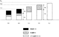
図2は、AC/DCアダプタ111の出力電力と負荷の消費電力の制御方法を説明する図で、図3はその手順を説明するフローチャートである。一例としては、AC/DCアダプタ111の定格電力Paを65W、充電器19および充電器119のそれぞれの最大消費電力を54Wとする。また、システム負荷15、115の最大消費電力は65Wとする。システム負荷15、115の最大消費電力は、マージンを含めてもAC/DCアダプタ111の定格電力Paを超えることはないものとする。ここで、負荷の最大消費電力の合計は173Wとなり定格電力Paを超えている。また、図2の第1の閾値Th1を33W、第2の閾値Th2を54Wとして、第2の閾値Th2が第1の閾値Th1よりも優先順位が高くなるように設定する。
FIG. 2 is a diagram for explaining a method for controlling the output power of the AC /
図3のブロック201では、電池パック25が搭載されたノートPC10とAC/DCアダプタ111がドッキング・ステーション100に接続され、ドッキング・ステーション100には電池パック125が装着されているものとする。また、充電器19、119には、電池コントローラ23、123によって、対応する電池パック25、125に、電池パック25、125から得た標準的な充電電圧の設定値および充電電流の設定値が設定されている。したがって、充電器19、119はAC/DCアダプタ111から電力が供給されると標準的な充電モードで充電を開始する。
3, it is assumed that the
定電流定電圧制御で充電するときは、充電器19、119の消費電力は、定電流領域で動作している間は電池の電圧が上昇するのに伴って上昇し、定電流動作から定電圧動作に切り替わるときに最大になり、定電圧動作に移行したあとは低下していく。ブロック201における充電器19、119の消費電力は、その時点での電池パック25、125の残容量により決まる。ブロック203で、電池コントローラ123は、コネクタ57を経由するラインがアース電位であるか否かによって、ノートPC10がドッキング・ステーション100に接続されたか否かを判断する。
When charging with constant current and constant voltage control, the power consumption of the
ノートPC10には、通常は電池パック25が装着されているので、電池コントローラ123が、ノートPC10がドッキング・ステーション100に接続されていると判断したときは、電池パック25と充電器19からなる充電システムがAC/DCアダプタ111の負荷として存在すると判断してもよい。充電システムは、電池パックが装着されていないときは電力を消費しない。本発明は、ノートPC10が複数の補助電池パックを含む複数の充電システムを搭載する場合にも適用できるので、電池コントローラ123は、ノートPC10がドッキング・ステーション100に接続されていると判断したときは、電池コントローラ23に問い合わせて電池パック25がノートPC10に実際に装着されているか否かを判断してもよい。
Since the battery pack 25 is usually attached to the
電池パック25がノートPC10に装着されていると判断した場合はブロック205に移行し、ノートPC10がドッキング・ステーション100に接続されていないと判断した場合、およびノートPC10が接続されていてもノートPC10に電池パック25が装着されていないと判断した場合はブロック251に移行する。ブロック205では、AC/DCアダプタ111がシステム負荷15、115、充電器19、119に電力を供給してユーザにノートPC10の使用環境を提供し、かつ電池パック25、125の充電を行う。このとき電池コントローラ123は電力検出器127から定期的にデータを受け取って、AC/DCアダプタ111の出力電力P(W)を測定する。
If it is determined that the battery pack 25 is attached to the
ブロック207では、電池パック25がノートPC10に装着されていると判断した電池コントローラ123は、プログラムに組み込まれていた第1の閾値Th1を充電器119に適用し、第2の閾値Th2を充電器19に適用して動作する。ブロック209で電池コントローラ123は、出力電力Pが、第1の閾値Th1に到達したか否かを判断する。出力電力Pが第1の閾値Th1に到達していないときは、図2の(A)に示すように、充電器19、充電器119にそれらが必要とする電力を供給する。具体的には、充電器19、充電器119は、電池パック25、125が要求した充電電流の設定値で動作する。本実施の形態では、システム負荷15、115の消費電力は制御対象から除外するが、本発明はシステム負荷15、115の消費電力を閾値に基づいて制御する場合も含む。
In
システム負荷15、115は、ユーザによるノートPC10の作業内容で消費電力が変動する。充電器19、119の消費電力は、定電流領域で充電していれば徐々に増大する。ブロック209で、図2(B)に示すように、3つの負荷のいずれかまたは複数の消費電力が増大して、出力電力Pが第1の閾値Th1に到達したと電池コントローラ123が判断したときはブロック211に移行する。ブロック211では、電池コントローラ123が、充電器119の電流の設定値を下げて充電器119の消費電力を低下させる。なお、充電器119が定電圧領域で充電している場合は、電池コントローラ123は、充電電圧の設定値を下げたり充電を停止したりすることができる。電池コントローラ123は、出力電力Pが、第1の閾値Th1を超えないように充電器119の閾値を変更する。
The system loads 15 and 115 vary in power consumption depending on the work contents of the
電池コントローラ123は、所定の時間間隔でAC/DCアダプタ111の出力電力を計算し、出力電力Pが第1の閾値Th1を超えたときは充電器119の充電電流の設定値を下げて消費電力を低減する。システム負荷15、115および充電器19またはいずれか一方の消費電力が増大すると、図2(C)に示すように充電器119の動作を停止しても出力電力Pが第1の閾値Th1を超えることを抑制できなくなる。ブロック213では、出力電力Pが第2の閾値Th2に到達したか否かを電池コントローラ123が判断する。ブロック213で、図2(D)に示すようにシステム負荷15、115および充電器19の消費電力またはいずれか一方が増大して、出力電力Pが第2の閾値Th2に到達したと電池コントローラ123が判断したときはブロック215に移行する。
The
ブロック215では、電池コントローラ123が、出力電力Pが第2の閾値Th2を超えたと判断したときは充電器19の充電電流の設定値を下げるように電池コントローラ23に指示する。電池コントローラ23は、電池コントローラ123の指示に基づいて充電器19の充電電流の設定値を変更して消費電力を低減する。なお、充電器19が定電圧領域で充電している場合は、電池コントローラ123から消費電力を低減する指示を受けた電池コントローラ23は、充電電圧の設定値を下げたり充電を停止したりすることができる。システム負荷15、115の最大消費電力はAC/DCアダプタ111の定格電力Pa以内に設定されているので、それ以後は、図2(E)に示すようにシステム負荷15、115に継続して電力が供給される。
In
ここで、ブロック211、ブロック215における充電器119、19の消費電力の制御について図4を参照して詳細に説明する。図4は、充電器119、19の消費電力を制御することにより、時間経過に応じてAC/DCアダプタ111の出力電力が変化する様子の3つの例を示す図である。図4(A)の例では、時刻t1まで、システム負荷15、115、充電器19、充電器119の合計の消費電力がライン301に示すように出力電力Pと等しくなっている。時刻t1で、出力電力Pが第1の閾値Th1に到達する。このとき、システム負荷15、115の消費電力と充電器19の消費電力の合計がP1で、充電器119の消費電力がP2であるものとする。すなわち、P1+P2=Pである。
Here, the control of the power consumption of the
時刻t1以降は、消費電力P1がライン303に添って漸増しているものとすると、電池コントローラ123はそれに併せて充電器119の消費電力をライン305に添って漸減させている。電池コントローラ123は、出力電力Pが第1の閾値Th1を超えた場合には、充電器119の充電電流の設定値を所定のステップ数だけ下げ、出力電力Pが第1の閾値Th1を下回った場合は、充電器119の充電電流の設定値を所定のステップ数だけ上げる。その結果、出力電力Pは、第1の閾値Th1に維持される。
Assuming that the power consumption P1 gradually increases along the
時刻t2では、消費電力P2がゼロに到達し、出力電力Pが消費電力P1に等しくなっている。そして時刻t2から時刻t3までの間は、さらに消費電力P1が増大して、時刻t3で出力電力Pが第2の閾値Th2に到達する。このとき、システム負荷15、115の消費電力がP3で充電器19の消費電力がP4であるものとする。すなわち、P3+P4=Pである。時刻t3以降は、消費電力P3がライン307に添って漸増しているものとすると、電池コントローラ123はそれに併せて充電器19の消費電力をライン309に添って漸減させている。
At time t2, the power consumption P2 reaches zero, and the output power P is equal to the power consumption P1. Then, between time t2 and time t3, the power consumption P1 further increases, and the output power P reaches the second threshold Th2 at time t3. At this time, it is assumed that the power consumption of the system loads 15 and 115 is P3 and the power consumption of the
電池コントローラ123は、出力電力Pが第2の閾値Th2を超えた場合には、充電器19の充電電流の設定値を所定のステップ数だけ下げ、出力電力Pが第2の閾値Th2を下回った場合は、充電器19の充電電流の設定値を所定のステップ数だけ上げる。その結果、出力電力Pは、第2の閾値Th2に維持される。時刻t4では、充電器19の消費電力がゼロに到達し、出力電力Pは消費電力P3に等しくなっている。時刻t4以降は、AC/DCアダプタ111の負荷が、システム負荷15、115だけになるので、時刻t5で消費電力P3が定格電力Paに到達したとしてもこれを超えることはないので継続して電力を供給することができる。なお、AC/DCアダプタ111にマージンがあれば、時刻t2、時刻t4で、充電器119、充電器19の消費電力をゼロに制御しないでわずかな電力による充電を継続させることでもよい。
When the output power P exceeds the second threshold Th2, the
この制御では、電池コントローラ123は、AC/DCアダプタ111の出力電力Pが第1の閾値Th1または第2の閾値Th2を超えたときに、AC/DCアダプタの出力電力Pが第1の閾値Th1または第2の閾値Th2に近づくように充電器119の消費電力P2または充電器119の消費電力P4を制御するといえる。この制御では、出力電力Pが第2の閾値Th2に到達するまでの間に充電器119の消費電力P2をゼロまたは最低にし、出力電力Pが定格電力Paに到達するまでの間に充電器19の消費電力P4をゼロまたは最低にすることができる。
In this control, when the output power P of the AC /
図4(B)の例は、時刻t1までは図4(A)と同じであるが、時刻t1以降において出力電力Pが時刻t3で第2の閾値に到達するまでライン321に添って漸増し、電池コントローラ123は、充電器119の消費電力P2をライン323に添って時刻t3まで漸減している。また、時刻t3以降において出力電力Pが時刻t5までライン321に添って漸増し、電池コントローラ123は、充電器19の消費電力をライン325に添って時刻t5まで漸減している。ここでは、出力電力Pが第2の閾値に到達するまでの間に充電器119の消費電力をゼロにし、出力電力Pが定格電力Paに到達するまでの間に充電器19の消費電力をゼロにするように制御する。
The example of FIG. 4B is the same as FIG. 4A until time t1, but after time t1, output power P gradually increases along
本実施の形態では、消費電力P2、P4は測定しないで出力電力Pだけに基づいて充電器119、19の消費電力を制御するが、この制御は、消費電力Pの値と充電器119、19の電流設定値の関係をプログラムに組み込んでおくことにより実現できる。具体的には、消費電力Pと第2の閾値Th2との差の電力と、充電器119の現在の電流の設定値に基づいて、消費電力Pが第2の閾値に到達したときに、充電器119の電流の設定値がゼロになるように制御する。たとえば、時刻t1での充電器119の設定電流値が10であり、第1の閾値Th1と第2の閾値Th2の差が20Wだとすれば、出力電力Pが第1の閾値Th1より5W上昇したときは、充電器119の設定値を5にし、20W上昇したときにはゼロにする。同様に、消費電力Pと定格電力Paとの差の電力と、充電器19の現在の電流の設定値に基づいて、消費電力Pが定格電力Paに到達したときに、充電器19の電流の設定値がゼロになるように制御する。したがって、ライン323、325の形状は、出力電力Pの変化に依存する。
In the present embodiment, the power consumption of the
図4(B)の方法も、図4(A)の方法も出力電力Pが第2の閾値に到達するまでの間に充電器119の消費電力がゼロになり、出力電力Pが定格電力Paに到達するまでの間に充電器19の消費電力がゼロになる点で共通性がある。図4(B)の方法は、図4(A)の方法に比べて、閾値のマージンが大きくなる可能性があるが、充電器119、19にはより長い時間電力を供給することができる。
In both the method of FIG. 4B and the method of FIG. 4A, the power consumption of the charger 119 becomes zero until the output power P reaches the second threshold, and the output power P becomes the rated power Pa. There is a commonality in that the power consumption of the
図4(C)の例は、時刻t1までは図4(A)、図4(B)と同じであるが、電池コントローラ123は、時刻t1でライン353に沿って充電器119の消費電力P2をゼロにする。時刻t1から時刻t2までは、出力電力Pがライン351に添ったシステム負荷15、115と充電器19の合計の消費電力P1に等しくなる。時刻t3で出力電力Pが第2の閾値に到達すると、電池コントローラ123は、ライン355に沿って充電器19の消費電力P4をゼロにする。時刻t4以降は、出力電力Pとシステム負荷15、115の消費電力P3が等しくなる。図4(C)の方法は、他の方法に比べて閾値のマージンを少なくすることができるが、充電器19、119に電力を供給する時間は短くなる。
4C is the same as FIG. 4A and FIG. 4B until time t1, but the
ブロック251では、AC/DCアダプタ111からシステム負荷15、115、充電器119に電力を供給して、ユーザにノートPC10の使用環境を提供し、かつ、電池パック125の充電を行う。ブロック253では、電池コントローラ123が、ノートPC10がドッキング・ステーション100に接続されていないこと、またはノートPC10が接続されていてもノートPC10に電池パック25が装着されていないことを認識して第2の閾値Th2を充電器119に適用して動作する。ブロック255で電池コントローラ123は、出力電力Pが、第2の閾値Th2に到達したか否かを判断する。出力電力Pが第2の閾値Th2に到達していないときは、電池コントローラ123は、システム負荷15、115、および充電器119にそれらが必要とする電力を供給する。
In
具体的には、充電器119は、電池パック125により提供された充電電流の設定値で動作する。電池コントローラ123は、出力電力Pが、第2の閾値Th2に到達したと判断したときは、ブロック257で充電器119の消費電力を低下させるように制御する。制御の方法は、図4で説明した方法を採用する。充電器119は、優先順位の高い充電器19が存在しない場合に、優先順位が繰り上げられて充電器19の閾値で消費電力が制御される。
Specifically, the charger 119 operates with the set value of the charging current provided by the
図3の手順によれば、充電器19、充電器119、およびシステム負荷15、115に対するAC/DCアダプタ111の定格電力に限界がある場合に、充電器19による電池パック25の充電を充電器119による電池パック125の充電よりも優先させ、かつ、最も優先順位の高いシステム負荷15、115の消費電力を制約しないため、ユーザの利便性に供するコンピュータ・システムにすることができる。また、図3の手順によれば、電池コントローラ123は、AC/DCアダプタ111の出力電力Pだけを測定して、3つの負荷または2つの負荷の消費電力を制御することができるので、ノートPC10がドッキング・ステーション100に接続されていないようなときにも、AC/DCアダプタ111の余剰電力を有効に活用して電池パック125の充電を短時間で完了することができる。
According to the procedure of FIG. 3, when the rated power of the AC /
以上、本発明を、コンピュータ・システムを例にして説明したが、本発明は共通の電力源に対する複数の負荷の消費電力の制御に適用することができる。また、3つの負荷を例にして説明したが制御する負荷の数に制約はない。その場合は、制御可能なすべての負荷に優先順位に従う各閾値を対応付け、負荷全体の消費電力がある閾値に到達したときに当該閾値に対応する負荷の消費電力を制限するように制御する。 Although the present invention has been described above by taking the computer system as an example, the present invention can be applied to control of power consumption of a plurality of loads with respect to a common power source. Further, although three loads have been described as an example, the number of loads to be controlled is not limited. In that case, each threshold value according to the priority order is associated with all controllable loads, and when the power consumption of the entire load reaches a certain threshold value, the power consumption of the load corresponding to the threshold value is controlled.
具体的には、ノートPC10およびドッキング・ステーション100またはいずれか一方が複数の充電システムを備える場合に適用することができる。また、複数の充電システムを備える外部充電器において、各充電システムに優先順位をつけて充電をする場合に適用することができる。また、当初優先順位の高い閾値を設定した負荷がその時点で実際に存在しないと判断した場合には、当該負荷に適用した閾値を1つ下位の負荷に対応付け、それ以下の優先順位の負荷に対する閾値を順番に繰り上げることができる。
Specifically, the present invention can be applied when the
これまで本発明について図面に示した特定の実施の形態をもって説明してきたが、本発明は図面に示した実施の形態に限定されるものではなく、本発明の効果を奏する限り、これまで知られたいかなる構成であっても採用することができることはいうまでもないことである。 Although the present invention has been described with the specific embodiments shown in the drawings, the present invention is not limited to the embodiments shown in the drawings, and is known so far as long as the effects of the present invention are achieved. It goes without saying that any configuration can be adopted.
所定の定格容量の電力源から複数の負荷に電力を供給するシステムに適用することができる。 The present invention can be applied to a system that supplies power to a plurality of loads from a power source having a predetermined rated capacity.
10…ノートPC
100…ドッキング・ステーション
127…電力検出器
10 ... Notebook PC
100 ...
Claims (8)
前記機能拡張装置に接続される所定の定格容量の第1のAC/DCアダプタと、
前記第1のAC/DCアダプタから電力の供給を受け、第1の充電器と第1の電池パックで構成され、前記機能拡張装置に搭載された第1の充電システムと、
前記携帯式コンピュータが前記機能拡張装置に接続されているときに前記第1のAC/DCアダプタから電力の供給を受け、前記第1の充電システムよりも優先順位が高く、第2の充電器と第2の電池パックで構成され、前記携帯式コンピュータに搭載された第2の充電システムと、
前記携帯式コンピュータが前記機能拡張装置に接続されているときに前記第1のAC/DCアダプタから電力の供給を受け、前記第2の充電システムよりも優先順位が高く、前記携帯式コンピュータがアクセスすることが可能なシステム負荷と、
前記第1の充電システムと前記第2の充電システムと前記システム負荷に電力を供給する前記第1のAC/DCアダプタの出力電力が第1の閾値に到達したときに前記第1の充電システムの消費電力を低下させ、前記第1のAC/DCアダプタの出力電力が前記第1の閾値より大きい第2の閾値に到達したときに前記第2の充電システムの消費電力を低下させるように制御する前記機能拡張装置に搭載された第1のコントローラと、
前記携帯式コンピュータが前記機能拡張装置に接続されていないときに前記携帯式コンピュータに電力を供給する所定の定格容量の第2のAC/DCアダプタと、
前記第2の電池パックまたは前記第1のコントローラからの指示に基づいて前記第2の充電システムの消費電力を制御する前記携帯式コンピュータに搭載された第2のコントローラとを有し、
前記携帯式コンピュータが前記機能拡張装置に接続されているときに前記第1のコントローラが前記第2のコントローラに前記第2の充電器に対する充電電流の設定値を送る
消費電力制御システム。 A power consumption control system comprising a portable computer and a function expansion device capable of connecting the portable computer,
A first AC / DC adapter having a predetermined rated capacity connected to the function expansion device;
A first charging system that is supplied with electric power from the first AC / DC adapter, includes a first charger and a first battery pack, and is mounted on the function expansion device;
When the portable computer is connected to the function expansion device, the portable computer receives power from the first AC / DC adapter, has a higher priority than the first charging system, and has a second charger, A second charging system comprising a second battery pack and mounted on the portable computer;
When the portable computer is connected to the function expansion device, the portable computer receives power from the first AC / DC adapter, has a higher priority than the second charging system, and is accessed by the portable computer. System load that can be
When the output power of the first AC / DC adapter that supplies power to the first charging system, the second charging system, and the system load reaches a first threshold, the first charging system Control to reduce power consumption, and to reduce power consumption of the second charging system when the output power of the first AC / DC adapter reaches a second threshold value that is greater than the first threshold value. A first controller mounted on the function expansion device;
A second AC / DC adapter of a predetermined rated capacity for supplying power to the portable computer when the portable computer is not connected to the function expansion device;
A second controller mounted on the portable computer that controls power consumption of the second charging system based on an instruction from the second battery pack or the first controller ;
The first controller sends a setting value of a charging current for the second charger to the second controller when the portable computer is connected to the function expansion device. Power consumption control system .
Priority Applications (2)
| Application Number | Priority Date | Filing Date | Title |
|---|---|---|---|
| JP2008154381A JP4944841B2 (en) | 2008-06-12 | 2008-06-12 | Power consumption control system and power consumption control method |
| US12/420,099 US8248031B2 (en) | 2008-06-12 | 2009-04-08 | Method for prioritizing load consumption within a notebook computer |
Applications Claiming Priority (1)
| Application Number | Priority Date | Filing Date | Title |
|---|---|---|---|
| JP2008154381A JP4944841B2 (en) | 2008-06-12 | 2008-06-12 | Power consumption control system and power consumption control method |
Publications (2)
| Publication Number | Publication Date |
|---|---|
| JP2009301281A JP2009301281A (en) | 2009-12-24 |
| JP4944841B2 true JP4944841B2 (en) | 2012-06-06 |
Family
ID=41414069
Family Applications (1)
| Application Number | Title | Priority Date | Filing Date |
|---|---|---|---|
| JP2008154381A Active JP4944841B2 (en) | 2008-06-12 | 2008-06-12 | Power consumption control system and power consumption control method |
Country Status (2)
| Country | Link |
|---|---|
| US (1) | US8248031B2 (en) |
| JP (1) | JP4944841B2 (en) |
Families Citing this family (17)
| Publication number | Priority date | Publication date | Assignee | Title |
|---|---|---|---|---|
| JP2011259625A (en) * | 2010-06-09 | 2011-12-22 | Sony Corp | Information processing apparatus and power supply control method |
| JP5306496B2 (en) * | 2012-02-06 | 2013-10-02 | 株式会社東芝 | Electronic device, electronic device control method, electronic device control program, electronic system |
| JP5548238B2 (en) * | 2012-06-08 | 2014-07-16 | レノボ・シンガポール・プライベート・リミテッド | Power system comprising two units and charging method |
| KR101648239B1 (en) * | 2012-06-29 | 2016-08-12 | 삼성에스디아이 주식회사 | Energy storage device and method for decreasing rush current |
| US9337661B2 (en) * | 2012-12-27 | 2016-05-10 | Intel Corporation | Power management system and method |
| GB201308107D0 (en) * | 2013-05-05 | 2013-06-12 | Rodrigues Paulo A | Dual external DC power brick/transformer splitter to provide seamless cutover redundant power supply to a single powered device |
| US10020665B2 (en) * | 2014-05-20 | 2018-07-10 | Intel Corporation | Power delivery system |
| JP2017529819A (en) * | 2014-07-22 | 2017-10-05 | アドバンスド マグネティック ソリューションズ リミティド | Power adapter and cable with control |
| JPWO2016047095A1 (en) * | 2014-09-26 | 2017-07-06 | パナソニックIpマネジメント株式会社 | Power supply |
| US9939849B2 (en) | 2014-10-30 | 2018-04-10 | Kabushiki Kaisha Toshiba | System with electronic device and extension device |
| JP6649579B2 (en) | 2015-12-22 | 2020-02-19 | 富士通クライアントコンピューティング株式会社 | Electronic system, function expansion device and power management program |
| CN109874366B (en) * | 2016-10-07 | 2023-03-17 | 索尼互动娱乐股份有限公司 | Electric machine and apparatus |
| TWI614600B (en) * | 2016-11-18 | 2018-02-11 | 廣達電腦股份有限公司 | Electronic device capable of dynamically determining the amount of current provided to an external device and methods for dynamically controlling current of an electronic device |
| DE112017006365T5 (en) * | 2016-12-19 | 2019-08-29 | Fujifilm Corporation | POWER SUPPLY SYSTEM, ELECTRONIC DEVICE AND POWER SUPPLY METHOD |
| WO2020123415A1 (en) * | 2018-12-09 | 2020-06-18 | Promptlink Communications, Inc. | Network management |
| JP7167791B2 (en) | 2019-03-20 | 2022-11-09 | トヨタ自動車株式会社 | Supply and demand control device |
| CN112328065A (en) * | 2020-10-26 | 2021-02-05 | 山东超越数控电子股份有限公司 | Method for controlling power consumption of notebook computer when power is switched on |
Family Cites Families (30)
| Publication number | Priority date | Publication date | Assignee | Title |
|---|---|---|---|---|
| US3894244A (en) * | 1973-10-03 | 1975-07-08 | Ross K Hill | Power limit and control system |
| US4034233A (en) * | 1976-07-22 | 1977-07-05 | Pacific Technology | Power monitoring and regulating circuit and method having an analog input representing power rate and a digital output for controlling the on/off states of a plurality of loads |
| JPH0773413B2 (en) * | 1990-07-31 | 1995-08-02 | 三洋電機株式会社 | External battery adapter and battery system |
| JP2648117B2 (en) * | 1995-02-22 | 1997-08-27 | 新潟日本電気株式会社 | Portable personal computer |
| JP3337878B2 (en) | 1995-07-17 | 2002-10-28 | キヤノン株式会社 | Electrical equipment |
| JPH1023681A (en) * | 1996-06-28 | 1998-01-23 | Toshiba Corp | Portable electronic apparatus |
| JPH1055868A (en) | 1996-08-09 | 1998-02-24 | Masami Fujii | Construction method for embedding grounding electrode |
| JPH1091290A (en) * | 1996-09-10 | 1998-04-10 | Canon Inc | Electronic equipment |
| JPH10198468A (en) * | 1997-01-09 | 1998-07-31 | Canon Inc | Battery controller, information processing system and battery controlling method |
| JPH10285822A (en) * | 1997-04-10 | 1998-10-23 | Brother Ind Ltd | Charger |
| JP3387786B2 (en) * | 1997-07-31 | 2003-03-17 | キヤノン株式会社 | Control device and charge control method thereof |
| JPH11212684A (en) * | 1998-01-22 | 1999-08-06 | Canon Inc | Electronic device, and power supply control method and its device |
| JP3280321B2 (en) * | 1998-09-14 | 2002-05-13 | 富士通株式会社 | Function expansion device and electronic equipment system |
| JP3297389B2 (en) | 1998-12-07 | 2002-07-02 | インターナショナル・ビジネス・マシーンズ・コーポレーション | Power consumption control method and electric equipment |
| JP4068275B2 (en) | 1999-12-08 | 2008-03-26 | インターナショナル・ビジネス・マシーンズ・コーポレーション | Charge control method and computer |
| JP2001331242A (en) * | 2000-05-22 | 2001-11-30 | Hitachi Ltd | Information processor and method for controlling its power consumption |
| US6977482B2 (en) * | 2003-02-11 | 2005-12-20 | O2Micro International Limited | Selector circuit for power management in multiple battery systems |
| US6861956B2 (en) * | 2001-07-10 | 2005-03-01 | Yingco Electronic Inc. | Remotely controllable wireless energy control unit |
| US6832135B2 (en) * | 2001-07-10 | 2004-12-14 | Yingco Electronic Inc. | System for remotely controlling energy distribution at local sites |
| TW200413896A (en) * | 2003-01-24 | 2004-08-01 | Mitac Technology Corp | Power management and control method of power supply and device thereof |
| US7791319B2 (en) * | 2003-02-21 | 2010-09-07 | Research In Motion Limited | Circuit and method of operation for an electrical power supply |
| US7010363B2 (en) * | 2003-06-13 | 2006-03-07 | Battelle Memorial Institute | Electrical appliance energy consumption control methods and electrical energy consumption systems |
| JP4701936B2 (en) * | 2005-09-09 | 2011-06-15 | ソニー株式会社 | Information processing apparatus, information processing method, and program thereof |
| JP2007102008A (en) * | 2005-10-06 | 2007-04-19 | Sharp Corp | Image forming apparatus |
| JP4920995B2 (en) * | 2006-03-03 | 2012-04-18 | エヌイーシーコンピュータテクノ株式会社 | Computer system |
| JP2007272341A (en) * | 2006-03-30 | 2007-10-18 | Toshiba Corp | Arithmetic device, arithmetic device system, and power control method |
| WO2007144825A1 (en) * | 2006-06-15 | 2007-12-21 | Koninklijke Philips Electronics N.V. | A method of balancing power consumption between loads. |
| US7781908B2 (en) * | 2007-07-19 | 2010-08-24 | Igo, Inc. | Output power port management control |
| EP2495845B1 (en) * | 2008-04-29 | 2014-05-14 | Dialog Semiconductor GmbH | Load current dependent reduction of charge battery current |
| JP4753100B2 (en) * | 2008-09-30 | 2011-08-17 | 独立行政法人 日本原子力研究開発機構 | Charging system |
-
2008
- 2008-06-12 JP JP2008154381A patent/JP4944841B2/en active Active
-
2009
- 2009-04-08 US US12/420,099 patent/US8248031B2/en active Active
Also Published As
| Publication number | Publication date |
|---|---|
| US8248031B2 (en) | 2012-08-21 |
| US20090309419A1 (en) | 2009-12-17 |
| JP2009301281A (en) | 2009-12-24 |
Similar Documents
| Publication | Publication Date | Title |
|---|---|---|
| JP4944841B2 (en) | Power consumption control system and power consumption control method | |
| JP4855444B2 (en) | Charging control system and control method | |
| US10620679B2 (en) | Prioritizing supplying electrical power by a power storage adapter to connected devices | |
| TWI625912B (en) | Mobile terminal | |
| JP6277273B2 (en) | Dynamic voltage regulation circuit and method | |
| US9261934B2 (en) | Dynamic response improvement of hybrid power boost technology | |
| US9372521B2 (en) | Systems and methods for providing auxiliary reserve current for powering information handling systems | |
| US6498460B1 (en) | Prioritization-based power management protocol in a computer system | |
| TWI603185B (en) | Power management apparatus and computer-readable medium | |
| EP2495845B1 (en) | Load current dependent reduction of charge battery current | |
| US8862907B2 (en) | Information processing apparatus and power supply control method | |
| JP4197189B2 (en) | Circuit for power supply and method of operation | |
| US8793518B2 (en) | Systems and methods for providing supplemental power to battery powered information handling systems | |
| JP5548238B2 (en) | Power system comprising two units and charging method | |
| US20180366967A1 (en) | Charging device and charging method | |
| JP2009033879A (en) | Charging system and charging method | |
| EP2505418A2 (en) | Power storage device, power storage method, and program | |
| US10673271B2 (en) | Efficient charging of multiple portable information handling systems based on learned charging characteristics | |
| CN103823542A (en) | Electronic apparatus and control method thereof | |
| US9252618B2 (en) | Terminals, terminal systems and charging/discharging methods thereof | |
| EP3148038B1 (en) | Charging control method and apparatus, terminal and computer storage medium | |
| JP2011034163A (en) | Method for controlling power consumption of portable computer | |
| CN114629187A (en) | Charging control method and device and electronic equipment |
Legal Events
| Date | Code | Title | Description |
|---|---|---|---|
| A977 | Report on retrieval |
Free format text: JAPANESE INTERMEDIATE CODE: A971007 Effective date: 20100408 |
|
| A131 | Notification of reasons for refusal |
Free format text: JAPANESE INTERMEDIATE CODE: A131 Effective date: 20100420 |
|
| A521 | Request for written amendment filed |
Free format text: JAPANESE INTERMEDIATE CODE: A523 Effective date: 20100622 |
|
| A131 | Notification of reasons for refusal |
Free format text: JAPANESE INTERMEDIATE CODE: A131 Effective date: 20110315 |
|
| A521 | Request for written amendment filed |
Free format text: JAPANESE INTERMEDIATE CODE: A523 Effective date: 20110513 |
|
| TRDD | Decision of grant or rejection written | ||
| A01 | Written decision to grant a patent or to grant a registration (utility model) |
Free format text: JAPANESE INTERMEDIATE CODE: A01 Effective date: 20120228 |
|
| A01 | Written decision to grant a patent or to grant a registration (utility model) |
Free format text: JAPANESE INTERMEDIATE CODE: A01 |
|
| A61 | First payment of annual fees (during grant procedure) |
Free format text: JAPANESE INTERMEDIATE CODE: A61 Effective date: 20120302 |
|
| R150 | Certificate of patent or registration of utility model |
Ref document number: 4944841 Country of ref document: JP Free format text: JAPANESE INTERMEDIATE CODE: R150 Free format text: JAPANESE INTERMEDIATE CODE: R150 |
|
| FPAY | Renewal fee payment (event date is renewal date of database) |
Free format text: PAYMENT UNTIL: 20150309 Year of fee payment: 3 |
|
| FPAY | Renewal fee payment (event date is renewal date of database) |
Free format text: PAYMENT UNTIL: 20150309 Year of fee payment: 3 |
|
| R250 | Receipt of annual fees |
Free format text: JAPANESE INTERMEDIATE CODE: R250 |
|
| R250 | Receipt of annual fees |
Free format text: JAPANESE INTERMEDIATE CODE: R250 |
|
| R250 | Receipt of annual fees |
Free format text: JAPANESE INTERMEDIATE CODE: R250 |
|
| R250 | Receipt of annual fees |
Free format text: JAPANESE INTERMEDIATE CODE: R250 |
|
| R250 | Receipt of annual fees |
Free format text: JAPANESE INTERMEDIATE CODE: R250 |
|
| R250 | Receipt of annual fees |
Free format text: JAPANESE INTERMEDIATE CODE: R250 |
|
| R250 | Receipt of annual fees |
Free format text: JAPANESE INTERMEDIATE CODE: R250 |
|
| R250 | Receipt of annual fees |
Free format text: JAPANESE INTERMEDIATE CODE: R250 |
|
| R250 | Receipt of annual fees |
Free format text: JAPANESE INTERMEDIATE CODE: R250 |
|
| R250 | Receipt of annual fees |
Free format text: JAPANESE INTERMEDIATE CODE: R250 |