JP4944249B2 - Method for requesting random access connection and mobile terminal therefor - Google Patents
Method for requesting random access connection and mobile terminal therefor Download PDFInfo
- Publication number
- JP4944249B2 JP4944249B2 JP2010520946A JP2010520946A JP4944249B2 JP 4944249 B2 JP4944249 B2 JP 4944249B2 JP 2010520946 A JP2010520946 A JP 2010520946A JP 2010520946 A JP2010520946 A JP 2010520946A JP 4944249 B2 JP4944249 B2 JP 4944249B2
- Authority
- JP
- Japan
- Prior art keywords
- signature
- random access
- signatures
- signature set
- mobile terminal
- Prior art date
- Legal status (The legal status is an assumption and is not a legal conclusion. Google has not performed a legal analysis and makes no representation as to the accuracy of the status listed.)
- Active
Links
- 238000000034 method Methods 0.000 title claims description 38
- 230000005540 biological transmission Effects 0.000 claims description 22
- 125000004122 cyclic group Chemical group 0.000 claims description 15
- 238000012545 processing Methods 0.000 claims description 10
- 230000006870 function Effects 0.000 description 17
- 230000008901 benefit Effects 0.000 description 10
- 238000010586 diagram Methods 0.000 description 10
- 238000004891 communication Methods 0.000 description 9
- 238000007726 management method Methods 0.000 description 6
- 230000011664 signaling Effects 0.000 description 6
- 238000005259 measurement Methods 0.000 description 4
- 230000004044 response Effects 0.000 description 4
- 238000010295 mobile communication Methods 0.000 description 3
- 230000004048 modification Effects 0.000 description 3
- 238000012986 modification Methods 0.000 description 3
- 230000008569 process Effects 0.000 description 3
- 238000013468 resource allocation Methods 0.000 description 3
- 230000006835 compression Effects 0.000 description 2
- 238000007906 compression Methods 0.000 description 2
- 239000012467 final product Substances 0.000 description 2
- 239000000047 product Substances 0.000 description 2
- 238000003860 storage Methods 0.000 description 2
- 230000004913 activation Effects 0.000 description 1
- 230000004075 alteration Effects 0.000 description 1
- 239000000919 ceramic Substances 0.000 description 1
- 238000004590 computer program Methods 0.000 description 1
- 238000001514 detection method Methods 0.000 description 1
- 238000005516 engineering process Methods 0.000 description 1
- 239000013067 intermediate product Substances 0.000 description 1
- 238000002955 isolation Methods 0.000 description 1
- 230000007774 longterm Effects 0.000 description 1
- 238000004519 manufacturing process Methods 0.000 description 1
- 238000002360 preparation method Methods 0.000 description 1
- 238000003825 pressing Methods 0.000 description 1
- 230000005477 standard model Effects 0.000 description 1
- 238000012384 transportation and delivery Methods 0.000 description 1
Images


Classifications
-
- H—ELECTRICITY
- H04—ELECTRIC COMMUNICATION TECHNIQUE
- H04W—WIRELESS COMMUNICATION NETWORKS
- H04W74/00—Wireless channel access, e.g. scheduled or random access
- H04W74/08—Non-scheduled or contention based access, e.g. random access, ALOHA, CSMA [Carrier Sense Multiple Access]
- H04W74/0866—Non-scheduled or contention based access, e.g. random access, ALOHA, CSMA [Carrier Sense Multiple Access] using a dedicated channel for access
-
- H—ELECTRICITY
- H04—ELECTRIC COMMUNICATION TECHNIQUE
- H04W—WIRELESS COMMUNICATION NETWORKS
- H04W74/00—Wireless channel access, e.g. scheduled or random access
- H04W74/002—Transmission of channel access control information
- H04W74/004—Transmission of channel access control information in the uplink, i.e. towards network
-
- H—ELECTRICITY
- H04—ELECTRIC COMMUNICATION TECHNIQUE
- H04W—WIRELESS COMMUNICATION NETWORKS
- H04W74/00—Wireless channel access, e.g. scheduled or random access
- H04W74/02—Hybrid access techniques
-
- H—ELECTRICITY
- H04—ELECTRIC COMMUNICATION TECHNIQUE
- H04W—WIRELESS COMMUNICATION NETWORKS
- H04W74/00—Wireless channel access, e.g. scheduled or random access
- H04W74/08—Non-scheduled or contention based access, e.g. random access, ALOHA, CSMA [Carrier Sense Multiple Access]
- H04W74/0833—Non-scheduled or contention based access, e.g. random access, ALOHA, CSMA [Carrier Sense Multiple Access] using a random access procedure
-
- H—ELECTRICITY
- H04—ELECTRIC COMMUNICATION TECHNIQUE
- H04W—WIRELESS COMMUNICATION NETWORKS
- H04W88/00—Devices specially adapted for wireless communication networks, e.g. terminals, base stations or access point devices
- H04W88/02—Terminal devices
-
- H—ELECTRICITY
- H04—ELECTRIC COMMUNICATION TECHNIQUE
- H04J—MULTIPLEX COMMUNICATION
- H04J13/00—Code division multiplex systems
- H04J13/0007—Code type
- H04J13/0055—ZCZ [zero correlation zone]
- H04J13/0059—CAZAC [constant-amplitude and zero auto-correlation]
-
- H—ELECTRICITY
- H04—ELECTRIC COMMUNICATION TECHNIQUE
- H04J—MULTIPLEX COMMUNICATION
- H04J13/00—Code division multiplex systems
- H04J13/0007—Code type
- H04J13/0055—ZCZ [zero correlation zone]
- H04J13/0059—CAZAC [constant-amplitude and zero auto-correlation]
- H04J13/0062—Zadoff-Chu
-
- H—ELECTRICITY
- H04—ELECTRIC COMMUNICATION TECHNIQUE
- H04L—TRANSMISSION OF DIGITAL INFORMATION, e.g. TELEGRAPHIC COMMUNICATION
- H04L27/00—Modulated-carrier systems
- H04L27/26—Systems using multi-frequency codes
- H04L27/2601—Multicarrier modulation systems
- H04L27/2602—Signal structure
- H04L27/2605—Symbol extensions, e.g. Zero Tail, Unique Word [UW]
- H04L27/2607—Cyclic extensions
Description
本発明は、ランダムアクセス(random access)に対する個別シグネチャー(dedicated signatures)を割当及び選択する異なる方法に関する。 The present invention relates to different methods for assigning and selecting dedicated signatures for random access.
汎用移動通信システム(UMTS)は、ヨーロッパシステムベースの広帯域コード分割多重接続(WCDMA)、移動通信用グローバルシステム(GSM)及び一般パケット無線サービス(GPRS)で動作する3世代(3G)非同期式移動通信システムである。UMTSのロング・ターム・エボリューション(LTE)は、UMTSを標準化する3世代パートナシッププロジェクト(3GPP)で議論中にある。 Universal Mobile Telecommunication System (UMTS) is a three generation (3G) asynchronous mobile communication system that operates in the European system based wideband code division multiple access (WCDMA), global system for mobile communication (GSM) and general packet radio service (GPRS) System. UMTS Long Term Evolution (LTE) is under discussion in the 3rd Generation Partnership Project (3GPP) that standardizes UMTS.
3GPP LTEは、高速パケット通信を可能にする技術である。ユーザ及びプロバイダの費用減少、サービス品質向上、及びカバレッジ及びシステム容量の拡張及び向上を含むLTEの目標に対して多くの方式が提案されてきた。3G LTEは、上位レベル要件として、減少したビット当たりの費用、増加したサービス利用性、周波数帯域の柔軟な使用、単純な構造、公開されたインターフェース、及び端末の適切な電力消費を要求する。 3GPP LTE is a technology that enables high-speed packet communication. Many schemes have been proposed for LTE goals including reducing user and provider costs, improving service quality, and extending and improving coverage and system capacity. 3G LTE demands reduced per-bit costs, increased service availability, flexible use of frequency bands, simple structure, open interfaces, and appropriate power consumption of terminals as higher level requirements.
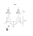
図1は、進化した汎用移動通信システム(E−UMTS)のネットワーク構造を示すブロック図である。E−UMTSは、LTEシステムとも称する。通信ネットワークは、広範囲に配置されて、音声及びパケットデータのような様々な通信サービスを提供する。 FIG. 1 is a block diagram illustrating a network structure of an evolved universal mobile communication system (E-UMTS). E-UMTS is also referred to as an LTE system. Communication networks are widely deployed to provide various communication services such as voice and packet data.
図1に示すように、E−UMTSネットワークは、進化したUMTS地上無線接続ネットワーク(E−UTRAN)及び進化したパケットコア(EPC)及び一つ以上のユーザ装置を含む。E−UTRANは、一つ以上の発展型基地局B(evolved NodeB:eNB)20を含むことができ、複数のユーザ装置(UE)10は、一つのセルに位置することができる。一つ以上のE−UTRANモビリティ管理機能(mobility management entity:MME)/発展型システム・アーキテクチャ(system architecture evolution:SAE)ゲートウェイ30は、ネットワークの末端に設けられて、外部ネットワークと接続されることができる。
As shown in FIG. 1, the E-UMTS network includes an evolved UMTS Terrestrial Radio Access Network (E-UTRAN) and an evolved packet core (EPC) and one or more user equipment. The E-UTRAN may include one or more evolved base stations B (eNB) 20, and a plurality of user equipments (UE) 10 may be located in one cell. One or more E-UTRAN mobility management entity (MME) / system architecture evolution (SAE)
本明細書で、“ダウンリンク”は、eNB 20からUE 10への通信を指し、“アップリンク”は、UEからeNBへの通信を指す。UE 10は、ユーザが携帯している通信装置で、移動局(MS)、ユーザ端末(UT)、加入者局(SS)または無線デバイスとも呼ばれる。 As used herein, “downlink” refers to communication from the eNB 20 to the UE 10, and “uplink” refers to communication from the UE to the eNB. The UE 10 is a communication device carried by a user, and is also called a mobile station (MS), a user terminal (UT), a subscriber station (SS), or a wireless device.
eNB 20は、ユーザプレーン及び制御プレーンのエンドポイントをUE 10に提供する。MME/SAEゲートウェイ30は、セッション及び移動性管理機能のエンドポイントをUE 10に提供する。eNB 20及びMME/SAEゲートウェイ30は、S1インターフェースを通じて接続されることができる。
The eNB 20 provides the UE 10 with user plane and control plane endpoints. The MME /
eNB 20は一般的にUE 10と通信する固定局であり、基地局(BS)またはアクセスポイントとも呼ばれる。一つのeNB 20がセルごとに配置されることができる。ユーザトラフィックまたは制御トラフィックを送信するためのインターフェースをeNB 20同士間に使用することができる。 The eNB 20 is generally a fixed station that communicates with the UE 10, and is also called a base station (BS) or an access point. One eNB 20 may be arranged for each cell. An interface for transmitting user traffic or control traffic can be used between the eNBs 20.
MMEは、ページングメッセージのeNB 20への配信、保安制御、アイドル状態モビリティ制御、SAEベアラ制御、及び非アクセスストラタム(non-access stratum:NAS)シグナリングの暗号化及び完全性保護を含む様々な機能を提供する。SAEゲートウェイホストは、ページング事由に対するU−プレーンパケットの終了及びUE 10移動性を支援するU−プレーンスイッチングを含む様々な機能を提供する。 The MME performs various functions including delivery of paging messages to the eNB 20, security control, idle state mobility control, SAE bearer control, and non-access stratum (NAS) signaling encryption and integrity protection. provide. The SAE gateway host provides various functions including U-plane packet termination for paging events and U-plane switching to support UE 10 mobility.
MME/SAEゲートウェイ30は、明確性のために本明細書では単に「ゲートウェイ」と称する。しかし、MME/SAEゲートウェイ30は、MME及びSAEゲートウェイの両者を含むことは明らかである。
The MME /
複数のノードがeNB 20とゲートウェイ30との間でS1インターフェースを通じて接続されることができる。eNB 20同士はX2インターフェースを通じて相互接続することができ、隣接のeNBはX2インターフェースを持つメッシュネットワーク構造を有することができる。
A plurality of nodes can be connected between the eNB 20 and the
図2Aは、一般的なE−UTRAN及び一般的なゲートウェイ30の構造を示すブロック図である。図2Aに示すように、eNB 20は、ゲートウェイ30に対する選択、無線リソース制御(RRC)活性化中のゲートウェイへのルーティング、ページングメッセージのスケジューリング及び送信、ブロードキャスト制御チャネル(BCCH)情報のスケジューリング及び送信、アップリンク及びダウンリンクの両方でUE 10のための動的リソース割当、eNB測定の構成及び準備、無線ベアラ制御、無線認可制御(Radio Admission Control;RAC)、及びLTE_ACTIVE状態で接続モビリティ制御のような機能を担うことができる。EPCで、ゲートウェイ30は、ページング発信、LTE_IDLE状態管理、ユーザプレーン暗号化、発展型システム・アーキテクチャ(SAE)ベアラ制御、及び非アクセス・ストラタム(NAS)シグナリングの暗号化及び完全性保護のような機能を担うことができる。
FIG. 2A is a block diagram illustrating a structure of a general E-UTRAN and a
図2B及び図2Cは、E−UMTSのためのユーザプレーンプロトコル及び制御プレーンプロトコルスタックを示すブロック図である。図2B及び図2Cに示すように、プロトコル層は、通信システムの技術分野に公知されているオープンシステム相互接続(OSI)標準モデルの下位の3層に基づいて第1層(L1)、第2層(L2)及び第3層(L3)に区別することができる。 2B and 2C are block diagrams illustrating a user plane protocol and control plane protocol stack for E-UMTS. As shown in FIGS. 2B and 2C, the protocol layer is based on the lower three layers of the Open System Interconnection (OSI) standard model known in the technical field of communication systems. A distinction can be made between layers (L2) and third layers (L3).
物理層、すなわち、第1層(L1)は、物理チャネルを用いて上位層への情報送信サービスを提供する。物理層は、上位レベルに位置しているメディア・アクセス制御(Medium Access Control;MAC)層に伝送チャネルを通じて接続され、伝送チャネルを通じてMAC層と物理層との間でデータ伝送がされる。データは、送信端の物理層と受信端の物理層の間のように、互いに異なる物理層の間で物理チャネルを通じて伝送される。 The physical layer, that is, the first layer (L1) provides an information transmission service to an upper layer using a physical channel. The physical layer is connected to a medium access control (MAC) layer located at a higher level through a transmission channel, and data is transmitted between the MAC layer and the physical layer through the transmission channel. Data is transmitted through physical channels between different physical layers, such as between the physical layer at the transmitting end and the physical layer at the receiving end.
第2層(L2)のMAC層は、論理チャネルを通じて上位層の無線リンク制御(RLC)層にサービスを提供する。第2層(L2)のRLC層は、信頼性あるデータの伝送を支援する。図2B及び2CにはRLC層が示されているが、MAC層がRLC機能を行う場合にはRLC層は省かれるということに留意されたい。 The MAC layer of the second layer (L2) provides services to an upper radio link control (RLC) layer through a logical channel. The RLC layer of the second layer (L2) supports reliable data transmission. Note that although the RLC layer is shown in FIGS. 2B and 2C, the RLC layer is omitted if the MAC layer performs RLC functions.
第2層(L2)のPDCP層は、余計な制御情報を減少させるヘッダ圧縮機能を担う。これは、相対的に小さい帯域幅を持つ無線インターフェースを通じてIPv4またはIPv6のようなインターネットプロトコル(IP)パケットを使用するデータを効率的に伝送させる。 The PDCP layer of the second layer (L2) bears a header compression function that reduces unnecessary control information. This efficiently transmits data using Internet Protocol (IP) packets such as IPv4 or IPv6 over a wireless interface with a relatively small bandwidth.
第3層(L3)の最下位部に位置している無線リソース制御(RRC)層は、制御プレーンでのみ定義され、構成、再構成、及び無線ベアラ(RB)のリリースと関連して論理チャネル、伝送チャネル及び物理チャネルを制御する。RBは、UE 10とE−UTRANとの間におけるデータ伝送のために第2層(L2)により提供されるサービスを意味する。 The radio resource control (RRC) layer located at the lowest layer of the third layer (L3) is defined only in the control plane, and is a logical channel in connection with configuration, reconfiguration, and radio bearer (RB) release. Control transmission channels and physical channels. RB means a service provided by Layer 2 (L2) for data transmission between UE 10 and E-UTRAN.
図2Bに示すように、RLC及びMAC層は、ネットワーク側のeNB 20で終了し、スケジューリング、自動再送要求(ARQ)、及びハイブリッド自動再送要求(HARQ)のような機能を果たす。PDCP層は、ネットワーク側のeNB 20で終了し、ヘッダ圧縮、完全性保護、及び暗号化のようなユーザプレーン機能を果たすことができる。 As shown in FIG. 2B, the RLC and MAC layers terminate at the eNB 20 on the network side and perform functions such as scheduling, automatic repeat request (ARQ), and hybrid automatic repeat request (HARQ). The PDCP layer terminates at the network side eNB 20 and can perform user plane functions such as header compression, integrity protection, and encryption.
図2Cに示すように、RLC及びMAC層は、ネットワーク側のeNB 20で終了し、制御プレーンにおけると同様の機能を果たす。図2Cに示すように、RRC層は、ネットワーク側のeNB 20で終了し、ブロードキャスティング、ページング、RRC接続管理、無線ベアラ(RB)制御、移動性機能、及びUE 10測定報告及び制御のような機能を担うことができる。図2Cに示すように、NAS制御プロトコルは、ネットワーク側のゲートウェイ30のMMEで終了し、SAEベアラ管理、認証、LTE_IDLE移動性ハンドリング、LTE_IDLEページング発信、及びゲートウェイとUE 10の間のシグナリングに対する保安制御のような機能を担うことができる。
As shown in FIG. 2C, the RLC and MAC layers terminate at the network side eNB 20 and perform the same function as in the control plane. As shown in FIG. 2C, the RRC layer terminates at eNB 20 on the network side, such as broadcasting, paging, RRC connection management, radio bearer (RB) control, mobility function, and UE 10 measurement reporting and control. Can take on the function. As shown in FIG. 2C, the NAS control protocol is terminated at the MME of the
NAS制御プロトコルは、3つの相異なる状態を用いることができる。LTE−DETACHED状態は、RRCエンティティがない場合に用いられる。LTE_IDLE状態は、最小UE 10情報を保存しながらRRC接続がない場合に用いられる。LTE_ACTIVE状態は、RRC状態が確立された場合に用いられる。また、RRC状態は、RRC_IDLE及びRRC_CONNECTEDのような2つの相異なる状態に区分することができる。
The NAS control protocol can use three different states. The LTE-DETACHED state is used when there is no RRC entity. The LTE_IDLE state is used when there is no RRC connection while preserving the
RRC_IDLE状態で、UEがNASによって構成された不連続受信(DRX)を特定し、UEにトラッキング領域でUEを唯一に識別するIDが割り当てられる限り、UE 10は、システム情報及びページング情報のブロードキャストを受信することができる。また、RRC_IDLE状態ではeNBにいかなるRRCコンテキストも保存されない。
As long as the UE identifies discontinuous reception (DRX) configured by the NAS in the RRC_IDLE state and the UE is assigned an ID that uniquely identifies the UE in the tracking domain, the
RRC_CONNECTED状態で、UE 10は、E−UTRAN RRC接続及びE−UTRANでのコンテキストを有し、これにより、データをeNBに/から送信及び/または受信することが可能である。また、UE 10は、チャネル品質情報及びフィードバック情報をeNBに報告することができる。
In the RRC_CONNECTED state, the
RRC_CONNECTED状態で、E−UTRANは、UE 10の属しているセルを知っている。したがって、ネットワークは、UE 10に/からデータを送信及び/または受信し、UEのハンドオーバーのような移動性を制御し、周辺セルに対するセル測定を行うことができる。
In the RRC_CONNECTED state, E-UTRAN knows the cell to which
RRC_IDLEモードで、UE 10は、ページングDRX(不連続受信)サイクルを特定する。具体的に、UE 10は、UE特定ページングDRXサイクル別の特定ページング時期にページング信号をモニタリングする。
In RRC_IDLE mode, the
図3は、従来のLTEハンドオーバー手順を示す。UE 10は、ソースeNB 20に測定報告を伝送する(S102)。ソースeNB 20は、ターゲットeNBにUE 10コンテキストと共にハンドオーバー要求メッセージを伝送する(S104)。
FIG. 3 shows a conventional LTE handover procedure. The
ターゲットeNB 20は、ソースeNBにハンドオーバー要求応答を伝送する(S106)。ハンドオーバー要求応答は、新しいCRNTI、ハンドオーバー命令メッセージの一部及びターゲットセルでのコンテンションフリー(contention-free)ランダムアクセスをするためのUE 10個別接続シグネチャーのようなランダムアクセスに関する情報を含む。シグネチャーは、この時点に予約される。
The
ソースeNB 20は、UEにハンドオーバー命令を伝送する(S108)。ハンドオーバー命令は、新しいC−RNTI及びUE 10が使用するための個別シグネチャーのようなランダムアクセスに関する情報を含む。
The
ランダムアクセス手順は、UE 10がタイミングアドバンス(TA)値を獲得するために、ハンドオーバー命令以後にターゲットセルで行われる。このようなランダムアクセス手順は、衝突を回避するために、シグネチャーがUE 10に予約されるコンテンションフリーである。
The random access procedure is performed in the target cell after the handover command in order for the
UE 10は、個別シグネチャーを用いてランダムアクセスプリアンブルを伝送し、これによりターゲットeNB 20でランダムアクセス手順を始める(S110)。ターゲットeNB 20は、ランダムアクセス応答メッセージをUE 10に伝送する(S112)。ランダムアクセス応答メッセージは、TA及びアップリンクリソース割当を含む。UE 10は、ハンドオーバー完了メッセージをターゲットeNB 20に伝送する(S114)。
The
LTEランダムアクセス手順は、コンテンションベース(contention-based)またはコンテンションフリーのいずれか一方でありうる。UE 10が使用可能なシグネチャーのセットからプリアンブルをランダムに選択する場合、ランダムアクセスプリアンブルはコンテンションベースである。UE 10が使用するシグネチャーが個別シグナリングを通じてeNB 20から割り当てられる場合、ランダムアクセスプリアンブルはコンテンションフリーである。
The LTE random access procedure can be either contention-based or contention free. When the
個別シグネチャー割当は、ハンドオーバー時に及びUE 10が時間−整列されていない場合にはダウンリンクデータの到着時に発生することができる。コンテンションベース及びコンテンションフリーの両方に対するランダムアクセスプリアンブルは、ゼロ相関領域を持ったZadoff-Chuシーケンス(ZC-ZCZ; Zadoff-Chu sequence with Zero Correlation Zone)に基づくべきである。現在、LTEランダムアクセス手順は、2セットのシグネチャーを用いる。
Dedicated signature assignment can occur at handover and upon arrival of downlink data if
本発明の一様態で、無線移動端末と基地局の間の無線接続接続を要求する方法が提供される。この方法は、少なくとも一つのシグネチャールートシーケンスインデックス、巡回シフトパラメータ、及び第1伝送フォーマットに対応する第1シグネチャーセットと第2伝送フォーマットに対応する第2シグネチャーセットとの境界を表すシグネチャーセット識別子を含む情報を受信する段階と、前記少なくとも一つのシグネチャールートシーケンスインデックス及び前記巡回シフトパラメータによってランダムアクセスシグネチャーを用意する段階と、を含み、前記ランダムアクセスシグネチャーの少なくとも一つは、前記第1シグネチャーセットと関連し、前記ランダムアクセスシグネチャーの残りは、前記第2シグネチャーセットと関連する。 In one aspect of the invention, a method for requesting a wireless connection between a wireless mobile terminal and a base station is provided. The method includes at least one signature root sequence index, a cyclic shift parameter, and a signature set identifier representing a boundary between a first signature set corresponding to the first transmission format and a second signature set corresponding to the second transmission format. Receiving information and providing a random access signature according to the at least one signature root sequence index and the cyclic shift parameter, wherein at least one of the random access signatures is associated with the first signature set The remainder of the random access signature is associated with the second signature set.
前記シグネチャーセット識別子は複数のステップを含み、前記複数のステップのそれぞれは、複数のシグネチャーを含むことが考慮される。前記シグネチャーセット識別子は、前記第1シグネチャーセットと前記第2シグネチャーセットとの間の複数の既設定された境界のうちの一つを含むことがさらに考慮される。 It is contemplated that the signature set identifier includes a plurality of steps, each of the plurality of steps including a plurality of signatures. It is further contemplated that the signature set identifier includes one of a plurality of preset boundaries between the first signature set and the second signature set.
本発明の他の様態で、基地局とのランダムアクセス接続を要求する移動端末機が提供される。この移動端末機は、情報を送信する送信ユニット、情報を受信する受信ユニット、情報を表示するディスプレイユニット、ユーザからの入力を受信する入力ユニットと、少なくとも一つのシグネチャールートシーケンスインデックス、巡回シフトパラメータ、及び第1伝送フォーマットに対応する第1シグネチャーセットと第2伝送フォーマットに対応する第2シグネチャーセットとの境界を表すシグネチャーセット識別子を含む受信情報を処理し、前記少なくとも一つのシグネチャールートシーケンスインデックス及び前記巡回シフトパラメータによってランダムアクセスシグネチャーを用意する処理ユニットと、を含み、前記ランダムアクセスシグネチャーの少なくとも一つは、前記第1シグネチャーセットと関連し、前記ランダムアクセスシグネチャーの残りは、前記第2シグネチャーセットと関連する。 In another aspect of the present invention, a mobile terminal that requests a random access connection with a base station is provided. The mobile terminal includes a transmitting unit for transmitting information, a receiving unit for receiving information, a display unit for displaying information, an input unit for receiving input from a user, at least one signature route sequence index, a cyclic shift parameter, Processing received information including a signature set identifier representing a boundary between a first signature set corresponding to the first transmission format and a second signature set corresponding to the second transmission format, and the at least one signature root sequence index and the A processing unit for preparing a random access signature according to a cyclic shift parameter, wherein at least one of the random access signatures is associated with the first signature set and the random access signature is The remaining scan signature is associated with the second signature set.
前記シグネチャーセット識別子は、複数のステップを含み、前記複数のステップのそれぞれは、複数のシグネチャーを含むことが考慮される。前記シグネチャーセット識別子は、前記第1シグネチャーセットと前記第2シグネチャーセットとの間の複数の既設定された境界のうちの一つを含むことがさらに考慮される。 It is contemplated that the signature set identifier includes a plurality of steps, each of the plurality of steps including a plurality of signatures. It is further contemplated that the signature set identifier includes one of a plurality of preset boundaries between the first signature set and the second signature set.
本発明の追加的な特徴及び長所は後述する明細書から説明され、部分的には説明から明らかになるか、または、本発明の実施からわかることができる。本発明の上述した一般的な説明及び後述する詳細な説明は両方も例示的で説明的なものであり、請求される発明の追加的な説明を提供するためのものであることは明らかである。 Additional features and advantages of the invention will be set forth in the description that follows, and in part will be apparent from the description, or may be learned from the practice of the invention. It will be apparent that both the foregoing general description of the invention and the detailed description below are exemplary and explanatory, and provide additional explanation of the claimed invention. .
これら及びその他の実施形態は、添付の図面を参照して後述する実施形態の詳細な説明から、当業者には容易且つ明白になり、本発明は、開示された特定実施形態に制限されることはない。 These and other embodiments will be readily and readily apparent to those skilled in the art from the following detailed description of the embodiments with reference to the accompanying drawings, and the present invention is limited to the specific embodiments disclosed. There is no.
第1方式は、コンテンションベースランダムアクセスで用いられるプリアンブルから完全に独立した多数のプリアンブルを生成できるという利点がある。第2方式は、追加的なZCインデックスが要らず、新しいルートシーケンスを用いる必要がないという利点がある。第3方式は、追加的なZCインデックスが要求されないという利点がある。第4方式は、コンテンションフリーRACHに利用可能なプリアンブルの個数が減少することによって衝突確率を増加させるという欠点がある。 The first method has an advantage that a large number of preambles completely independent from the preamble used in contention-based random access can be generated. The second scheme has the advantage that no additional ZC index is required and a new root sequence need not be used. The third method has an advantage that an additional ZC index is not required. The fourth method has a drawback that the collision probability is increased by reducing the number of preambles available for contention-free RACH.
添付の図面は、本発明の追加的な理解を提供するために含まれ、本明細書に組み込まれて一部分を構成し、本発明の原理を説明するために提供される説明と共に本発明の実施形態を示す。互いに異なる図面で同一の参照番号によって参照される本発明の特徴、要素、及び様態は、一つ以上の実施形態による同一、均等、または類似の特徴、要素、または様態を示す。 The accompanying drawings are included to provide an additional understanding of the invention, and are incorporated in and constitute a part of this specification, together with the description provided to illustrate the principles of the invention. The form is shown. Features, elements, and aspects of the present invention that are referred to by the same reference numerals in different figures illustrate the same, equivalent, or similar features, elements, or aspects according to one or more embodiments.
以下、本発明の好適な実施形態について詳細に説明し、それらの例示を添付の図面に示す。本発明は、個別シグネチャーを割り当てる数個の方式を提示する。 Reference will now be made in detail to the preferred embodiments of the present invention, examples of which are illustrated in the accompanying drawings. The present invention presents several schemes for assigning individual signatures.
第1方式において、シグネチャーは、区別されたルートシーケンスから割り当てられる。この方式で、コンテンションフリーランダムアクセスに用いられるシグネチャーは、コンテンションベースランダムアクセスプリアンブルを生成するために用いられるZCルートシーケンスと異なるZCルートシーケンスを用いて生成される。 In the first scheme, signatures are assigned from distinguished root sequences. In this manner, a signature used for contention-free random access is generated using a ZC root sequence that is different from the ZC root sequence used to generate a contention-based random access preamble.
第1方式は、コンテンションベースランダムアクセスで用いられるプリアンブルから完全に独立した多数のプリアンブルを生成できるという利点を有する。一方、第1方式は、セルで新しいルートシーケンスを用いることが結果としては、干渉の増加、セル当たり使用されるルートシーケンスの増加、及び相互相関及び検出の複雑度増加につながるという欠点を有する。 The first scheme has the advantage that a large number of preambles can be generated that are completely independent of the preamble used in contention-based random access. On the other hand, the first scheme has the disadvantage that using a new route sequence in the cell results in increased interference, more route sequences used per cell, and increased cross-correlation and detection complexity.
第2方式において、シグネチャーは、ランダムシグネチャールートインデックスの未使用の空間から割り当てられる。この方式で、異なるコードリソースが個別及びランダムシグネチャーに対して使用される。 In the second scheme, signatures are allocated from unused space in the random signature root index. In this manner, different code resources are used for individual and random signatures.
巡回シフト値がセルサイズに関連し、よって、所定のセルサイズでシフトが最大伝播遅延よりも大きくなければならないため、コンテンションベースシグネチャー機会で用いられる最後のシーケンスインデックスは、64シグネチャーを生成するために必ずしも完全に割り当てられる必要はない。これにより、残余未使用のシグネチャーがコンテンションフリー接続手順に割り当てられることができる。 Since the cyclic shift value is related to the cell size, and therefore the shift must be greater than the maximum propagation delay for a given cell size, the last sequence index used in the contention-based signature opportunity generates 64 signatures Need not be fully allocated. This allows a residual unused signature to be assigned to the contention-free connection procedure.
第2方式は、追加的なZCインデックスが必要でなく、新しいルートシーケンスを用いる必要がないという利点を有する。一方、第2方式は、残余シグネチャー機会の個数が固定されず、セルサイズ、すなわち、巡回シフトの長さによって0になることもあるという欠点を有する。 The second scheme has the advantage that no additional ZC index is required and there is no need to use a new root sequence. On the other hand, the second scheme has a drawback that the number of residual signature opportunities is not fixed and may be zero depending on the cell size, that is, the length of the cyclic shift.
第3方式において、シグネチャーは、異なる時間/周波数リソースを用いる同一のルートインデックスから割り当てられる。同一のコードリソースが個別及びランダムシグネチャーに対して使用される。この方式で、コンテンションベース及びコンテンションフリーRACHシグネチャー機会は、同一のZCシーケンスインデックスを通じて同一の巡回シフトされたバージョンから割り当てられる。 In the third scheme, signatures are assigned from the same route index using different time / frequency resources. The same code resource is used for individual and random signatures. In this manner, contention-based and contention-free RACH signature opportunities are allocated from the same cyclically shifted version through the same ZC sequence index.
第3方式の利点は、追加的なZCインデックスが要求されないこと、すなわち、新しいルートシーケンスを使用する必要がないということである。一方、第3方式は、コンテンションフリーとコンテンションベースプリアンブルの間にコード区別がないため、コンテンションフリー及びコンテンションベースのプリアンブル間の区別が、RACHに使用された時間/周波数リソースによって行われ、そのため、追加的なシグナリングが要求されるという欠点を有する。 The advantage of the third scheme is that no additional ZC index is required, i.e. it is not necessary to use a new root sequence. On the other hand, in the third method, since there is no code distinction between contention-free and contention-based preambles, the distinction between contention-free and contention-based preambles is performed by time / frequency resources used for RACH. Therefore, it has the disadvantage that additional signaling is required.
第4方式で、シグネチャーは、同一の時間/周波数リソースを用いる同一のルートインデックスから割り当てられる。この方式は、コンテンションベースランダムアクセス手順で使用されるプリアンブルのセットから準静的方式でいくつかのプリアンブルの予約を許容することから構成される。例えば、16プリアンブルが予約されることができる。第4方式は、コンテンションフリーRACHに利用可能なプリアンブルの個数が減少することによって衝突確率を増加させるという欠点を有する。 In the fourth scheme, signatures are assigned from the same route index using the same time / frequency resource. This scheme consists of allowing the reservation of several preambles in a quasi-static manner from the set of preambles used in the contention based random access procedure. For example, 16 preambles can be reserved. The fourth method has a drawback that the collision probability is increased by reducing the number of preambles available for contention-free RACH.
好ましい方式は、第2方式及び第4方式のハイブリッドである。このハイブリッド方式は、新しいルートシーケンス及びシグナリングによって取り込まれる干渉を最小化するために、上記4つの方式の利点及び欠点を考慮する。 A preferred method is a hybrid of the second method and the fourth method. This hybrid scheme takes into account the advantages and disadvantages of the above four schemes in order to minimize the interference introduced by new route sequences and signaling.
ハイブリッド方式は、未使用の空間があれば、ランダムシグネチャールートインデックスの未使用空間から個別シグネチャーを割り当てる。第4方式は、個別シグネチャーがさらに必要であり、いくつかのプリアンブルがコンテンションベースランダムアクセスプリアンブルから予約される場合に用いられる。コンテンションベースシグネチャーセットの中で予約可能なシグネチャーの個数はあらかじめ設定される。 In the hybrid method, if there is an unused space, an individual signature is assigned from the unused space of the random signature root index. The fourth scheme is used when more individual signatures are needed and several preambles are reserved from the contention based random access preamble. The number of signatures that can be reserved in the contention-based signature set is preset.
図4は、本発明による個別シグネチャー割当を示す図である。図4で、UE 10は、UEが個別シグネチャーを使用するセルで利用される巡回シフト値及びルートシーケンスを知り、個別シグネチャーの割当のためにハイブリッド方法が用いられると仮定する。
FIG. 4 is a diagram illustrating individual signature assignment according to the present invention. In FIG. 4, it is assumed that the
UE 10の使用のためにどんなシグネチャーが予約されたかをUEに指示する一つの方法は、利用可能なシグネチャーの全体個数の中でいずれかの数を単純に指示することであり、UEは、シグネチャーを生成するためにUEが何回の巡回シフトを適用しなければならないかがわかる。利用可能なシグネチャーの全体個数は、所定のセルで使用された全てのルートシーケンスから生成されうるシグネチャーの個数である。巡回シフト数が、ルートシーケンス#Aに適用可能な巡回シフトの最大数よりも高いと、UE 10は、ルートシーケンス#Bに巡回シフトを適用しなければならないということが事実上わかる。
One way to indicate to the UE what signatures are reserved for use of
しかし、このような方法は、eNB 20が少なくても6ビットの情報をUE 10に伝送することを要求する。この方法を最適化するいくつかのオプションが存在する。全てのオプションに対して、BCCH上でブロードキャスティングするようにして、コンテンションベース接続を行うUE 10に、予約されたシグネチャーの数を指示しなければならない。
However, such a method requires that at least 6 bits of information be transmitted to the
個別シグネチャーを割り当てる第1オプションは、情報ビットの数を6ビットよりも小さく減少させることであり、図4Aにおいて矢印で示すように、予約が許可されるコンテンションベースランダムアクセスに対するシグネチャーがルートシーケンスから生成された最後のシグネチャーであり、末端からナンバリングが始まると標準で定義することによる。 The first option for assigning individual signatures is to reduce the number of information bits to less than 6 bits, and the signatures for contention-based random access for which reservations are allowed, as indicated by the arrows in FIG. 4A, from the root sequence. This is the last signature generated, by defining in the standard that numbering starts from the end.
第1オプションは、例えば、予約できるシグネチャーの数が16と固定されている場合に単に4ビットが必要であるように、予約できるシグネチャーの数に依存する。例えば、eNB 20は、シグネチャー64を予約し、情報“3”をUE 10に伝送できる。図4Aに示すように、3個の未使用シグネチャーが利用可能である。第1オプションは、予約されたシグネチャーに対するZCインデックス上の空間が連続的であり、未使用空間前にインデックスの最後に位置することを要求する。
The first option depends on the number of signatures that can be reserved, for example if only 4 bits are required if the number of signatures that can be reserved is fixed at 16. For example, the
第1オプションの一つの欠点は、予約できるシグネチャーが全て同一のセットからであるため、UE 10が要求されるリソース/チャネル品質を表示することのように、セットを選択できないということである。第1オプションは、また、ただ一つのセットでコンテンションベースに利用可能なシグネチャーの個数を減少させ、ユーザのただ一つのカテゴリーに対する衝突可能性を増加させる。
One disadvantage of the first option is that the set can not be selected, as the
個別シグネチャーを割り当てる第2オプションは、第1オプションの欠点に対処するものである。第2オプションは、コンテンションベースランダムアクセスに対して用いられる64シグネチャーのうち、インデックスの最後に予約されたシグネチャーを割り当てる代わりに、2セットのシグネチャーの間でセットの大きさに比例するように個別シグネチャーを割り当てる。 The second option for assigning individual signatures addresses the shortcomings of the first option. The second option is that of the 64 signatures used for contention-based random access, instead of assigning the reserved signature at the end of the index, the two signatures are individually proportional to the set size. Assign a signature.
例えば、64コンテンションベースランダムアクセスシグネチャーのうち、Nrシグネチャーが予約できると、それらのシグネチャーは、一部分は第1セットの終端に存在し、他の部分は第2セットの始端に存在するように2セットの間に予約される。2セットのうちそれぞれのセットで予約されるシグネチャーの数は、下記の数式によって計算することができる:
NRset1=ceil(Nset1/64*(Nr-Nunused))であり、
NRset2=Nr-NRset1-Nunused
ここで、
Nset1 セット1のシグネチャーの数
Nset2 セット2のシグネチャーの数
Nunused ルートシーケンスで使用されないシグネチャーの数
NRset1 セット1で予約されたシグネチャーの数
NRset2 セット2で予約されたシグネチャーの数
Ceil 整数(upper integer)を表す。
For example, out of 64 contention-based random access signatures, if Nr signatures can be reserved, those signatures are 2 such that some are at the end of the first set and the other are at the beginning of the second set. Reserved during set. The number of signatures reserved in each of the two sets can be calculated by the following formula:
NRset1 = ceil (Nset1 / 64 * (Nr-Nunused))
NRset2 = Nr-NRset1-Nunused
here,
Nset1 Number of
Nset2 Number of
Nunused Number of signatures not used in the root sequence
NRset1 Number of signatures reserved in
NRset2 Number of signatures reserved in
Ceil Represents an upper integer.
第2オプションにどんなシグネチャーを利用するかをUE 10に指示する2つの代案がある。第1代案は、やや最適化し足りない代案で、ZCインデックスの未使用空間で利用可能なシグネチャーの数に依存する所定の上限と共に、6から8ビットまでの数を持つシグネチャーを指示する。
There are two alternatives to instruct
図4Bに示す第2代案は、予約されうるシグネチャーの数に依存しているオフセット情報のビット数と共に、使用するシグネチャーを指示するためにオフセット情報を伝送することで構成される。例えば、未使用空間無しで16シグネチャーが個別化される場合には、4ビットが必要である。カウンティングは、図4Bのセット1の最初の予約可能なシグネチャーからセット2の最後の予約可能なシグネチャーに向かって行われる、または、シグネチャーがインデックスの未使用空間から提供された場合には、インデックスの終端からシーケンスの始端に向かって行われる。
The second alternative shown in FIG. 4B consists of transmitting offset information to indicate the signature to be used, along with the number of bits of offset information depending on the number of signatures that can be reserved. For example, if 16 signatures are individualized with no unused space, 4 bits are required. Counting is done from the first reservable signature of
図4Bに示すように、UE 10は、個別シグネチャーを割り当てるために、第2オプションの2グループのシグネチャーの間で選択しなければならない。図3に示すメッセージ3(Message 3)でデータ伝送に対するリソース割当を最適化するために、UE 10は、要求されるリソースによるシグネチャーを受け取ることができ、eNB 20が、個別シグネチャーと共にメッセージ3で使用される伝送フォーマットをUEに指示することができる。
As shown in FIG. 4B, the
個別シグネチャーを選択するためのこのオプションの利点は、eNB 20がただ一つのシグネチャーを指定するということである。このオプションの欠点は、図3に示すメッセージ3の大きさが、割り当てられたシグネチャーを収容しなければならないということである。
The advantage of this option for selecting individual signatures is that the
個別シグネチャーを選択するための代案オプションは、eNB 20がそれぞれのシグネチャーセットから一つずつ毎度2個のシグネチャーを予約し、UE 10が送信すべきデータの量によってシグネチャーを選択することである。eNB 20は、UE 10がそれぞれの予約された個別シグネチャーに対して、図3に示すメッセージ3のどのような伝送フォーマット及び/または無線条件を使用できるかを指示しなければならない。このオプションの欠点は、2シグネチャーが予約されなければならないということである。
An alternative option for selecting individual signatures is that the
図5は、移動局(MS)またはUE 10のブロック図である。UE 10は、プロセッサ(または、デジタル信号プロセッサ)510、RFモジュール535、電力管理モジュール505、アンテナ540、バッテリー555、ディスプレイ515、キーパッド520、メモリ530、SIMカード525(オプションでありうる)、スピーカー545及びマイクロホン550を含む。
FIG. 5 is a block diagram of a mobile station (MS) or
ユーザが、例えば、キーパッド520のボタンを押したり、または、マイクロホン550を用いた音声駆動によって電話番号のような指示情報を入力する。マイクロプロセッサ510は、指示情報を受信及び処理して、電話番号をダイヤルするなどの、適切な機能を行う。動作データが加入者アイデンティティモジュール(SIM)カード525またはメモリモジュール530から抽出されて、機能を果たすことができる。また、プロセッサ510は、ユーザの参照及び便宜のために、指示及び動作情報をディスプレイ515に表示することができる。
The user inputs instruction information such as a telephone number by pressing a button on the
プロセッサ510は、指示情報をRFモジュール535に提供し、例えば、音声通信データを含む無線信号を伝送するなど、通信を開始する。RFモジュール535は、無線信号を受信及び送信するための受信機及び送信機を含む。アンテナ541は、無線信号の送信及び受信を容易にする。無線信号を受信すると、RFモジュール535は、プロセッサ510による処理のために信号を基底帯域周波数にフォーワーディング及び変換する。処理された信号は、聞くことのできるまたは読むことのできる情報に変換され、例えば、スピーカー545を通じて出力される。プロセッサ510は、本明細書に説明された様々な処理を行うために必要なプロトコル及び機能を含む。
The
実施例によって、本発明は、全的にハードウェア具現、全的にソフトウェア具現、またはハードウェア及びソフトウェア構成要素を含む具現の形態を有することができる。ソフトウェア具現は、ファームウェア、常駐ソフトウェア、マイクロコードなどを含むことができるが、これに制限されない。 Depending on the embodiment, the present invention may have a form of implementation that is entirely hardware, entirely software, or that includes hardware and software components. Software implementations may include, but are not limited to, firmware, resident software, microcode, etc.
また、本発明は、コンピュータまたは任意の命令実行システムによりまたはこれらに接続されることによって使用されるプログラムコードを提供するコンピュータ利用可能またはコンピュータ読み取り可能媒体からアクセス可能なコンピュータプログラム製品の形態を有することができる。本説明の目的のために、コンピュータ利用可能またはコンピュータ読み取り可能媒体は、命令実行システム、装置、またはデバイスによりまたはこれらに接続されることによって使用されるプログラムを包含、記憶、通信、伝播、または伝送できる任意の装置でありうる。 The invention also has the form of a computer program product accessible from a computer-usable or computer-readable medium that provides program code for use by or connected to a computer or any instruction execution system. Can do. For purposes of this description, a computer-usable or computer-readable medium includes, stores, communicates, propagates, or transmits a program used by or connected to an instruction execution system, apparatus, or device. It can be any device that can.
プログラムコードを記憶及び/または実行するのに適したデータ処理システムは、システムバスを通じてメモリ要素と直接的または間接的に接続された一つ以上のプロセッサを含む。メモリ要素は、プログラムコードの実際実行中に用いられるローカルメモリ、バルク貯蔵所、及び実行中にバルク貯蔵所からコードが抽出されなければならない回数を減少するために少なくともいくつかのプログラムコードの臨時貯蔵所を提供するキャッシュメモリを含むことができる。 A data processing system suitable for storing and / or executing program code will include one or more processors coupled directly or indirectly to memory elements through a system bus. The memory element is a temporary storage of at least some program code to reduce the number of times local code used during the actual execution of program code, the bulk repository, and the number of times code must be extracted from the bulk repository during execution. A cache memory that provides the location can be included.
他の構成要素がシステムに接続されることができる。入力/出力またはI/O装置(キーボード、ディスプレイ、ポインティング装置などを含むが、これに限定されることはない)は、直接または媒介I/O制御機を通じてシステムに接続されることができる。ネットワークアダプター(例えば、モデム、ケーブルモデム、イーサネット(登録商標)カード)はシステムと接続されて、データプロセシングシステムが他のプロセシングシステムまたは遠隔プリンタまたは記憶デバイスと媒介私設または公衆ネットワークを通じて接続されるようにする。 Other components can be connected to the system. Input / output or I / O devices (including but not limited to keyboards, displays, pointing devices, etc.) can be connected to the system either directly or through an intermediary I / O controller. Network adapters (eg, modems, cable modems, Ethernet cards) are connected to the system so that the data processing system is connected to other processing systems or remote printers or storage devices through an intermediary private or public network To do.
ロジックコード、プログラム、モジュール、プロセス、方法、及びそれぞれの方法のそれぞれの要素が行われる順序は、あくまでも例示的なものであることを明らかにしたい。実施形態によって、本開示で別の指示がされない限り、それらは任意の順序でまたは並列的に行われることもできる。また、ロジックコードは或る特定プログラミング言語と関連したり制限されず、分散、非分散、または多重プロセシング環境の一つ以上のプロセッサ上で実行される一つ以上のモジュールを含むことができる。 It should be clarified that the logic code, the program, the module, the process, the method, and the order in which each element of each method is performed are merely exemplary. Depending on the embodiment, they may be performed in any order or in parallel unless otherwise indicated in this disclosure. In addition, logic code is not associated with or limited to a particular programming language and can include one or more modules that execute on one or more processors in a distributed, non-distributed, or multiple processing environment.
上述した方法は、集積回路チップの製造で用いられることができる。結果的な集積回路チップは、未加工のウエハ形態で(すなわち、多数のパッケージされていないチップを有する単一ウエハとして)、ベアダイ(bare die)として、またはパッケージングされた形態で製造者により分配されることができる。後者の場合、(マザーボードまたは他の上位レベルキャリアに付着されるリードを有するプラスチックキャリアのような)単一チップパッケージまたは(埋め込みインターコネクションまたは表面インターコネクションのいずれか一方または両方を有するセラミックキャリアのような)マルチチップパッケージにチップが実装される。 The method described above can be used in the manufacture of integrated circuit chips. The resulting integrated circuit chip is distributed by the manufacturer in raw wafer form (ie, as a single wafer with multiple unpackaged chips), as a bare die, or in packaged form. Can be done. In the latter case, such as a single chip package (such as a plastic carrier with leads attached to a motherboard or other upper level carrier) or a ceramic carrier (either embedded interconnect or surface interconnect or both) N) A chip is mounted on a multichip package.
いずれの場合にも、チップは(a)マザーボードのような中間製品、または(b)最終製品の一部分として他のチップ、分離回路要素、及び/または他の信号処理デバイスと一緒に集積される。最終製品は、おもちゃ及びその他の低級(low-end)アプリケーションからディスプレイ、キーボードまたはその他の入力装置、及び中央プロセッサを持つ高級コンピュータ製品に至る、集積回路チップを含む任意の製品にもなりうる。 In either case, the chip is integrated with (a) an intermediate product, such as a motherboard, or (b) other chips, isolation circuitry and / or other signal processing devices as part of the final product. The final product can be any product that includes integrated circuit chips, ranging from toys and other low-end applications to high-end computer products with displays, keyboards or other input devices, and a central processor.
したがって、本発明が添付の特許請求の範囲の思想及び範囲内で修正及び変更を加えて実行されることができることは明らかである。発明の詳細な説明は、開示された形態そのままに本発明を総網羅したり制限するためのものではない。開示された実施形態の上記の及び様々な他の適用及び組合せは本発明の範囲内に含まれ、特許請求の範囲及びその均等物の全体範囲によりさらに定められる。 Thus, it will be apparent that the invention may be practiced with modification and alteration within the spirit and scope of the appended claims. The detailed description of the invention is not intended to be exhaustive or to limit the invention to the precise form disclosed. The above and various other applications and combinations of the disclosed embodiments are included within the scope of the present invention and are further defined by the claims and their full scope of equivalents.
本発明は、その思想または必須な特徴を逸脱しない限度内で様々な形態で具現されることができるので、上記の実施形態は、特に特定されない限り、前述した説明の細部内容によって制限されることはなく、添付の特許請求の範囲の思想及び範囲内で定義されるものとして広く解釈しなければならないことが理解できる。したがって、特許請求の範囲の境界及び範囲に属するあらゆる修正及び変更、またはそれらの境界及び範囲の均等物は、添付の特許請求の範囲に含まれるように意図される。 Since the present invention can be embodied in various forms without departing from the spirit or essential features thereof, the above-described embodiments are limited by the detailed contents of the above description unless otherwise specified. Rather, it should be understood that it should be broadly construed as defined within the spirit and scope of the appended claims. Accordingly, all modifications and changes belonging to the boundaries and scope of the claims, or equivalents thereof, are intended to be included within the scope of the appended claims.
前述の実施形態及び利点は単に例示的なもので、本発明を制限するように解釈してはならない。本教示は、他の形式の装置にも容易に適用されることができる。 The foregoing embodiments and advantages are merely exemplary and should not be construed as limiting the invention. The present teachings can be readily applied to other types of devices.
本発明の説明は、例示的なものとして意図され、特許請求の範囲を制限するように意図されたものではない。多くの変形、修正、及び変更は、当該技術に熟練した当業者には明白である。特許請求の範囲で、手段+機能(means-plus-function)節は、記載された機能を行いながら、本明細書に説明された構造及び構造的均等物だけでなく均等な構造を含むように意図される。 The description of the present invention is intended to be illustrative and is not intended to limit the scope of the claims. Many variations, modifications, and changes will be apparent to those skilled in the art. In the claims, the means-plus-function section includes equivalent structures as well as the structures and structural equivalents described herein, while performing the described functions. Intended.
本発明は、ランダムアクセスに対する個別シグネチャーを割当及び選択するための異なる方法を対象とする。 The present invention is directed to different methods for assigning and selecting individual signatures for random access.
Claims (6)
少なくとも一つのシグネチャールートシーケンスインデックス、巡回シフトパラメータ、及び第1伝送フォーマットに対応する第1シグネチャーセットと第2伝送フォーマットに対応する第2シグネチャーセットの間の境界を表すシグネチャーセット識別子を含む情報を受信し、
前記少なくとも一つのシグネチャールートシーケンスインデックス及び前記巡回シフトパラメータによってランダムアクセスシグネチャーを用意すること、
を含み、
前記ランダムアクセスシグネチャーの少なくとも一つは、前記第1シグネチャーセットと関連し、前記ランダムアクセスシグネチャーの残りは、前記第2シグネチャーセットと関連する、ランダムアクセス接続要求方法。A method for requesting a random access connection between a wireless mobile terminal and a base station,
Receive information including at least one signature root sequence index, a cyclic shift parameter, and a signature set identifier representing a boundary between a first signature set corresponding to the first transmission format and a second signature set corresponding to the second transmission format. And
Providing a random access signature according to the at least one signature root sequence index and the cyclic shift parameter;
Including
The random access connection request method, wherein at least one of the random access signatures is associated with the first signature set, and the remainder of the random access signature is associated with the second signature set.
前記複数のステップのそれぞれは複数のシグネチャーを含む、請求項1に記載のランダムアクセス接続要求方法。The signature set identifier includes a plurality of steps;
The random access connection request method according to claim 1, wherein each of the plurality of steps includes a plurality of signatures.
情報を送信する送信ユニットと、
情報を受信する受信ユニットと、
情報を表示するディスプレイユニットと、
ユーザからの入力を受信する入力ユニットと、
少なくとも一つのシグネチャールートシーケンスインデックス、巡回シフトパラメータ、及び第1伝送フォーマットに対応する第1シグネチャーセットと第2伝送フォーマットに対応する第2シグネチャーセットの間の境界を表すシグネチャーセット識別子を含む受信情報を処理し、前記少なくとも一つのシグネチャールートシーケンスインデックス及び前記巡回シフトパラメータによってランダムアクセスシグネチャーを用意する処理ユニットと、
を含み、
前記ランダムアクセスシグネチャーの少なくとも一つは、前記第1シグネチャーセットと関連し、前記ランダムアクセスシグネチャーの残りは、前記第2シグネチャーセットと関連する、移動端末機。A mobile terminal requesting a random access connection with a base station,
A transmission unit for transmitting information;
A receiving unit for receiving information;
A display unit for displaying information;
An input unit that receives input from the user;
Reception information including at least one signature root sequence index, a cyclic shift parameter, and a signature set identifier representing a boundary between a first signature set corresponding to the first transmission format and a second signature set corresponding to the second transmission format. A processing unit for processing and preparing a random access signature according to the at least one signature root sequence index and the cyclic shift parameter;
Including
A mobile terminal, wherein at least one of the random access signatures is associated with the first signature set, and the remainder of the random access signature is associated with the second signature set.
前記複数のステップのそれぞれは、複数のシグネチャーを含む、請求項4に記載の移動端末機。The signature set identifier includes a plurality of steps;
The mobile terminal of claim 4, wherein each of the plurality of steps includes a plurality of signatures.
Applications Claiming Priority (3)
| Application Number | Priority Date | Filing Date | Title |
|---|---|---|---|
| US95611707P | 2007-08-15 | 2007-08-15 | |
| US60/956,117 | 2007-08-15 | ||
| PCT/KR2008/004753 WO2009022878A2 (en) | 2007-08-15 | 2008-08-14 | Signaling for preamble used for random access |
Related Child Applications (1)
| Application Number | Title | Priority Date | Filing Date |
|---|---|---|---|
| JP2012045382A Division JP5357285B2 (en) | 2007-08-15 | 2012-03-01 | Method for requesting random access connection and mobile terminal therefor |
Publications (2)
| Publication Number | Publication Date |
|---|---|
| JP2010537472A JP2010537472A (en) | 2010-12-02 |
| JP4944249B2 true JP4944249B2 (en) | 2012-05-30 |
Family
ID=40351314
Family Applications (2)
| Application Number | Title | Priority Date | Filing Date |
|---|---|---|---|
| JP2010520946A Active JP4944249B2 (en) | 2007-08-15 | 2008-08-14 | Method for requesting random access connection and mobile terminal therefor |
| JP2012045382A Active JP5357285B2 (en) | 2007-08-15 | 2012-03-01 | Method for requesting random access connection and mobile terminal therefor |
Family Applications After (1)
| Application Number | Title | Priority Date | Filing Date |
|---|---|---|---|
| JP2012045382A Active JP5357285B2 (en) | 2007-08-15 | 2012-03-01 | Method for requesting random access connection and mobile terminal therefor |
Country Status (6)
| Country | Link |
|---|---|
| US (4) | US8570992B2 (en) |
| EP (2) | EP2188919B1 (en) |
| JP (2) | JP4944249B2 (en) |
| KR (1) | KR100984303B1 (en) |
| CN (1) | CN101785217B (en) |
| WO (2) | WO2009022881A2 (en) |
Families Citing this family (29)
| Publication number | Priority date | Publication date | Assignee | Title |
|---|---|---|---|---|
| CN103068062B (en) | 2006-03-20 | 2016-12-28 | 光学无线技术有限责任公司 | Mobile station apparatus and method of random access |
| JP4944249B2 (en) | 2007-08-15 | 2012-05-30 | エルジー エレクトロニクス インコーポレイティド | Method for requesting random access connection and mobile terminal therefor |
| KR100926571B1 (en) * | 2007-12-06 | 2009-11-12 | 한국전자통신연구원 | Method for transmitting and receiving random access response information in radio communication system, base station device and terminal unit thereof |
| US8649353B2 (en) * | 2008-03-04 | 2014-02-11 | Interdigital Patent Holdings, Inc. | Method and apparatus for accessing a random access channel by selectively using dedicated or contention-based preambles during handover |
| CN102113401B (en) * | 2008-06-23 | 2014-07-09 | 诺基亚公司 | Method and apparatus for performing random access procedure using soft-dedicated preambles |
| CN105099597B (en) * | 2009-03-13 | 2018-02-02 | Lg电子株式会社 | Consider the performed switching of uplink/downlink component carrier setting |
| CN101841889B (en) * | 2009-03-19 | 2014-11-05 | 中兴通讯股份有限公司 | Method for acquiring random access information and user facility |
| CN101860929B (en) | 2009-04-13 | 2013-06-12 | 中兴通讯股份有限公司 | Inter-base station switching method |
| US8929324B2 (en) * | 2009-07-16 | 2015-01-06 | Qualcomm Incorporated | Facilitating noise estimation in wireless communication |
| JP5322832B2 (en) * | 2009-08-06 | 2013-10-23 | シャープ株式会社 | Mobile station apparatus, base station apparatus, radio communication system, and random access method |
| CN101998637B (en) * | 2009-08-18 | 2014-06-11 | 华为技术有限公司 | Method and device for configuring precursor |
| JP2011142532A (en) * | 2010-01-08 | 2011-07-21 | Sharp Corp | Wireless communication system, base station apparatus, mobile station device, wireless communication method, and integrated circuit |
| JP2013017060A (en) * | 2011-07-05 | 2013-01-24 | Sharp Corp | Wireless communication system, base station device, mobile station device, wireless communication method, and integrated circuit |
| JP6135056B2 (en) * | 2012-07-11 | 2017-05-31 | 株式会社バッファロー | COMMUNICATION SYSTEM, COMMUNICATION METHOD, AND RELAY DEVICE |
| ES2783884T3 (en) | 2012-07-31 | 2020-09-18 | Huawei Tech Co Ltd | Network method, apparatus, device, and system for adding a secondary service cell |
| US9648558B2 (en) | 2012-09-10 | 2017-05-09 | Huawei Technologies Co., Ltd. | System and method for user equipment centric unified system access in virtual radio access network |
| US11356216B2 (en) * | 2013-01-10 | 2022-06-07 | Texas Instruments Incorporated | Methods and apparatus for dual connectivity operation in a wireless communication network |
| WO2015016754A1 (en) * | 2013-07-29 | 2015-02-05 | Telefonaktiebolaget L M Ericsson (Publ) | Methods and devices for contention based random access |
| US9277465B1 (en) | 2013-08-23 | 2016-03-01 | Sprint Communications Company L.P. | Contention-free handoff return in a wireless network |
| US9615344B2 (en) * | 2013-12-19 | 2017-04-04 | Qualcomm Incorporated | Enhanced random access procedure for air-to-ground communications |
| US20170078933A1 (en) * | 2014-03-14 | 2017-03-16 | Telefonaktiebolaget Lm Ericsson (Publ) | Method and Apparatus for a Handover using Dedicated Random Access Resource |
| JP6773638B2 (en) * | 2014-07-18 | 2020-10-21 | ザ リージェンツ オブ ザ ユニバーシティ オブ カリフォルニア | Devices and methods for retaining gas in microfeatures on the surface of the liquid |
| WO2016137366A1 (en) * | 2015-02-24 | 2016-09-01 | Telefonaktiebolaget Lm Ericsson (Publ) | Method and apparatus for resolving preamble collisions |
| US9949195B1 (en) * | 2015-12-15 | 2018-04-17 | Sprint Spectrum L.P. | Contention-free mobile access for handover to a relay base station with wireless backhaul |
| CN108307413B (en) * | 2016-09-30 | 2023-06-30 | 华为技术有限公司 | Access method, terminal equipment and base station |
| KR102530275B1 (en) * | 2017-06-26 | 2023-05-09 | 삼성전자 주식회사 | Preamble generation method, preamble setting method and apparatus, random access method, device, user equipment and base station |
| JP6421227B2 (en) * | 2017-11-16 | 2018-11-07 | ▲ホア▼▲ウェイ▼技術有限公司Huawei Technologies Co.,Ltd. | Method, apparatus, device and network system for adding a secondary cell |
| US10959273B2 (en) * | 2019-02-04 | 2021-03-23 | Qualcomm Incorporated | Preamble sequence configuration for random access channel (RACH) |
| US20230100539A1 (en) * | 2021-09-17 | 2023-03-30 | Qualcomm Incorporated | Flexible random access channel configurations |
Family Cites Families (21)
| Publication number | Priority date | Publication date | Assignee | Title |
|---|---|---|---|---|
| KR100327104B1 (en) | 1998-12-05 | 2002-07-31 | 한국전자통신연구원 | Arbitrary connection apparatus and method of reverse common channel in code division multiple access method |
| ES2367548T3 (en) | 1999-03-24 | 2011-11-04 | Qualcomm Incorporated | MULTIPLE RESERVATION ACCESS. |
| GB9925896D0 (en) | 1999-11-03 | 1999-12-29 | Koninkl Philips Electronics Nv | Radio communication system |
| US7103027B2 (en) * | 1999-12-14 | 2006-09-05 | Interdigital Technology Corporation | Random access channel preamble detection |
| JP3613457B2 (en) * | 2000-01-18 | 2005-01-26 | 株式会社エヌ・ティ・ティ・ドコモ | CDMA mobile communication system, random access control method thereof, and base station apparatus |
| DE10008653A1 (en) * | 2000-02-24 | 2001-09-06 | Siemens Ag | Improvements in a radio communication system |
| GB0007337D0 (en) * | 2000-03-28 | 2000-05-17 | Koninkl Philips Electronics Nv | Radio communication system |
| GB0008488D0 (en) | 2000-04-07 | 2000-05-24 | Koninkl Philips Electronics Nv | Radio communication system and method of operating the system |
| US7433683B2 (en) | 2000-12-28 | 2008-10-07 | Northstar Acquisitions, Llc | System for fast macrodiversity switching in mobile wireless networks |
| CN103068062B (en) * | 2006-03-20 | 2016-12-28 | 光学无线技术有限责任公司 | Mobile station apparatus and method of random access |
| US8098745B2 (en) * | 2006-03-27 | 2012-01-17 | Texas Instruments Incorporated | Random access structure for wireless networks |
| EP2028871B1 (en) * | 2006-06-15 | 2018-01-24 | Godo Kaisha IP Bridge 1 | Radio transmission device and radio transmission method |
| JP4964241B2 (en) | 2006-08-17 | 2012-06-27 | パナソニック株式会社 | Wireless transmission apparatus and wireless transmission method |
| EA014639B1 (en) | 2006-10-31 | 2010-12-30 | Шарп Кабусики Кайся | Mobile communication system, base station apparatus and mobile station apparatus |
| KR20090086993A (en) * | 2006-12-28 | 2009-08-14 | 후지쯔 가부시끼가이샤 | Wireless communication system, base station, and random access channel transmission method |
| US20100284350A1 (en) * | 2007-06-07 | 2010-11-11 | Nokia Corporation | Apparatus, method and computer program product providing flexible preamble sequence allocation |
| US8064546B2 (en) * | 2007-06-14 | 2011-11-22 | Texas Instruments Incorporated | Random access preamble detection for long term evolution wireless networks |
| US9357564B2 (en) * | 2007-06-19 | 2016-05-31 | Texas Instruments Incorporated | Signaling of random access preamble parameters in wireless networks |
| US8773968B2 (en) * | 2007-08-06 | 2014-07-08 | Texas Instruments Incorporated | Signaling of random access preamble sequences in wireless networks |
| US8676201B2 (en) * | 2007-08-10 | 2014-03-18 | Telefonaktiebolaget L M Ericsson (Publ) | E-UTRAN and handover |
| JP4944249B2 (en) | 2007-08-15 | 2012-05-30 | エルジー エレクトロニクス インコーポレイティド | Method for requesting random access connection and mobile terminal therefor |
-
2008
- 2008-08-14 JP JP2010520946A patent/JP4944249B2/en active Active
- 2008-08-14 US US12/673,757 patent/US8570992B2/en active Active
- 2008-08-14 EP EP08793270.3A patent/EP2188919B1/en active Active
- 2008-08-14 KR KR1020107005145A patent/KR100984303B1/en active IP Right Grant
- 2008-08-14 CN CN2008801036361A patent/CN101785217B/en active Active
- 2008-08-14 WO PCT/KR2008/004756 patent/WO2009022881A2/en active Application Filing
- 2008-08-14 WO PCT/KR2008/004753 patent/WO2009022878A2/en active Application Filing
- 2008-08-14 US US12/673,158 patent/US8305964B2/en active Active
- 2008-08-14 EP EP08793267.9A patent/EP2188917B1/en active Active
-
2012
- 2012-03-01 JP JP2012045382A patent/JP5357285B2/en active Active
- 2012-09-14 US US13/620,579 patent/US9363828B2/en active Active
-
2013
- 2013-09-30 US US14/042,204 patent/US9131474B2/en active Active
Also Published As
| Publication number | Publication date |
|---|---|
| CN101785217A (en) | 2010-07-21 |
| US8305964B2 (en) | 2012-11-06 |
| JP2010537472A (en) | 2010-12-02 |
| EP2188919A2 (en) | 2010-05-26 |
| WO2009022881A2 (en) | 2009-02-19 |
| EP2188919A4 (en) | 2011-03-02 |
| US9131474B2 (en) | 2015-09-08 |
| US20140029548A1 (en) | 2014-01-30 |
| KR100984303B1 (en) | 2010-09-30 |
| US20130012219A1 (en) | 2013-01-10 |
| KR20100043272A (en) | 2010-04-28 |
| EP2188917B1 (en) | 2016-11-30 |
| WO2009022881A3 (en) | 2009-04-16 |
| CN101785217B (en) | 2013-08-21 |
| WO2009022878A3 (en) | 2009-04-02 |
| WO2009022878A2 (en) | 2009-02-19 |
| US9363828B2 (en) | 2016-06-07 |
| JP2012130065A (en) | 2012-07-05 |
| US8570992B2 (en) | 2013-10-29 |
| EP2188917A2 (en) | 2010-05-26 |
| US20110261752A1 (en) | 2011-10-27 |
| JP5357285B2 (en) | 2013-12-04 |
| EP2188917A4 (en) | 2011-03-02 |
| EP2188919B1 (en) | 2016-04-20 |
| US20110081912A1 (en) | 2011-04-07 |
Similar Documents
| Publication | Publication Date | Title |
|---|---|---|
| JP5357285B2 (en) | Method for requesting random access connection and mobile terminal therefor | |
| US9894684B2 (en) | Method for performing random access procedure in wireless communication system | |
| US8781471B2 (en) | Dedicated signature assignment | |
| US20080188219A1 (en) | Use of dedicated rach signatures | |
| US20110287776A1 (en) | Determination of user equipment antenna capability | |
| US20120008575A1 (en) | Random access resource configuration | |
| EP2253175A1 (en) | Rach preamble response with flexible ul allocation | |
| US8493854B2 (en) | Method for avoiding collision using identifier in mobile network |
Legal Events
| Date | Code | Title | Description |
|---|---|---|---|
| A977 | Report on retrieval |
Free format text: JAPANESE INTERMEDIATE CODE: A971007 Effective date: 20120118 |
|
| TRDD | Decision of grant or rejection written | ||
| A01 | Written decision to grant a patent or to grant a registration (utility model) |
Free format text: JAPANESE INTERMEDIATE CODE: A01 Effective date: 20120131 |
|
| A01 | Written decision to grant a patent or to grant a registration (utility model) |
Free format text: JAPANESE INTERMEDIATE CODE: A01 |
|
| A61 | First payment of annual fees (during grant procedure) |
Free format text: JAPANESE INTERMEDIATE CODE: A61 Effective date: 20120301 |
|
| R150 | Certificate of patent or registration of utility model |
Free format text: JAPANESE INTERMEDIATE CODE: R150 Ref document number: 4944249 Country of ref document: JP Free format text: JAPANESE INTERMEDIATE CODE: R150 |
|
| FPAY | Renewal fee payment (event date is renewal date of database) |
Free format text: PAYMENT UNTIL: 20150309 Year of fee payment: 3 |
|
| R250 | Receipt of annual fees |
Free format text: JAPANESE INTERMEDIATE CODE: R250 |
|
| R250 | Receipt of annual fees |
Free format text: JAPANESE INTERMEDIATE CODE: R250 |
|
| R250 | Receipt of annual fees |
Free format text: JAPANESE INTERMEDIATE CODE: R250 |
|
| R250 | Receipt of annual fees |
Free format text: JAPANESE INTERMEDIATE CODE: R250 |
|
| R250 | Receipt of annual fees |
Free format text: JAPANESE INTERMEDIATE CODE: R250 |
|
| R250 | Receipt of annual fees |
Free format text: JAPANESE INTERMEDIATE CODE: R250 |
|
| R250 | Receipt of annual fees |
Free format text: JAPANESE INTERMEDIATE CODE: R250 |
|
| R250 | Receipt of annual fees |
Free format text: JAPANESE INTERMEDIATE CODE: R250 |
|
| R250 | Receipt of annual fees |
Free format text: JAPANESE INTERMEDIATE CODE: R250 |
|
| R250 | Receipt of annual fees |
Free format text: JAPANESE INTERMEDIATE CODE: R250 |