JP4942765B2 - Combined OFDM and MC-CDMA and fast cell switching for circuit switching traffic - Google Patents
Combined OFDM and MC-CDMA and fast cell switching for circuit switching traffic Download PDFInfo
- Publication number
- JP4942765B2 JP4942765B2 JP2008553179A JP2008553179A JP4942765B2 JP 4942765 B2 JP4942765 B2 JP 4942765B2 JP 2008553179 A JP2008553179 A JP 2008553179A JP 2008553179 A JP2008553179 A JP 2008553179A JP 4942765 B2 JP4942765 B2 JP 4942765B2
- Authority
- JP
- Japan
- Prior art keywords
- users
- channel
- partitioning
- network
- cdma
- Prior art date
- Legal status (The legal status is an assumption and is not a legal conclusion. Google has not performed a legal analysis and makes no representation as to the accuracy of the status listed.)
- Expired - Fee Related
Links
- 238000000034 method Methods 0.000 claims description 81
- 238000012546 transfer Methods 0.000 claims description 66
- 238000000638 solvent extraction Methods 0.000 claims description 34
- 238000004891 communication Methods 0.000 claims description 28
- 230000007480 spreading Effects 0.000 claims description 15
- 238000010295 mobile communication Methods 0.000 claims description 10
- 230000001360 synchronised effect Effects 0.000 claims description 8
- 238000005192 partition Methods 0.000 claims 3
- 230000002441 reversible effect Effects 0.000 description 39
- 230000008569 process Effects 0.000 description 33
- 230000006870 function Effects 0.000 description 16
- 238000012545 processing Methods 0.000 description 15
- 238000010586 diagram Methods 0.000 description 14
- 230000011664 signaling Effects 0.000 description 13
- 230000005540 biological transmission Effects 0.000 description 7
- 230000001413 cellular effect Effects 0.000 description 7
- 230000004044 response Effects 0.000 description 7
- 210000004027 cell Anatomy 0.000 description 6
- 238000013461 design Methods 0.000 description 5
- 230000010267 cellular communication Effects 0.000 description 4
- 238000001228 spectrum Methods 0.000 description 4
- 230000008859 change Effects 0.000 description 3
- 230000000694 effects Effects 0.000 description 3
- 238000013507 mapping Methods 0.000 description 3
- 230000007246 mechanism Effects 0.000 description 3
- 238000012986 modification Methods 0.000 description 3
- 230000004048 modification Effects 0.000 description 3
- 108010003272 Hyaluronate lyase Proteins 0.000 description 2
- 239000003795 chemical substances by application Substances 0.000 description 2
- 230000003111 delayed effect Effects 0.000 description 2
- 238000001514 detection method Methods 0.000 description 2
- 238000005516 engineering process Methods 0.000 description 2
- 239000012634 fragment Substances 0.000 description 2
- 238000005259 measurement Methods 0.000 description 2
- 241001522296 Erithacus rubecula Species 0.000 description 1
- 108700026140 MAC combination Proteins 0.000 description 1
- 230000003213 activating effect Effects 0.000 description 1
- 230000004913 activation Effects 0.000 description 1
- 230000006978 adaptation Effects 0.000 description 1
- 238000013475 authorization Methods 0.000 description 1
- 210000004271 bone marrow stromal cell Anatomy 0.000 description 1
- 230000002301 combined effect Effects 0.000 description 1
- 239000002131 composite material Substances 0.000 description 1
- 238000007596 consolidation process Methods 0.000 description 1
- 238000012937 correction Methods 0.000 description 1
- 238000009792 diffusion process Methods 0.000 description 1
- 239000000463 material Substances 0.000 description 1
- 239000000203 mixture Substances 0.000 description 1
- 238000003825 pressing Methods 0.000 description 1
- 238000012216 screening Methods 0.000 description 1
- 238000000926 separation method Methods 0.000 description 1
- 238000010200 validation analysis Methods 0.000 description 1
Images


Classifications
-
- H—ELECTRICITY
- H04—ELECTRIC COMMUNICATION TECHNIQUE
- H04L—TRANSMISSION OF DIGITAL INFORMATION, e.g. TELEGRAPHIC COMMUNICATION
- H04L5/00—Arrangements affording multiple use of the transmission path
- H04L5/0001—Arrangements for dividing the transmission path
- H04L5/0014—Three-dimensional division
- H04L5/0016—Time-frequency-code
- H04L5/0021—Time-frequency-code in which codes are applied as a frequency-domain sequences, e.g. MC-CDMA
-
- H—ELECTRICITY
- H04—ELECTRIC COMMUNICATION TECHNIQUE
- H04L—TRANSMISSION OF DIGITAL INFORMATION, e.g. TELEGRAPHIC COMMUNICATION
- H04L1/00—Arrangements for detecting or preventing errors in the information received
- H04L1/12—Arrangements for detecting or preventing errors in the information received by using return channel
- H04L1/16—Arrangements for detecting or preventing errors in the information received by using return channel in which the return channel carries supervisory signals, e.g. repetition request signals
- H04L1/18—Automatic repetition systems, e.g. Van Duuren systems
- H04L1/1867—Arrangements specially adapted for the transmitter end
- H04L1/1887—Scheduling and prioritising arrangements
-
- H—ELECTRICITY
- H04—ELECTRIC COMMUNICATION TECHNIQUE
- H04L—TRANSMISSION OF DIGITAL INFORMATION, e.g. TELEGRAPHIC COMMUNICATION
- H04L27/00—Modulated-carrier systems
- H04L27/0008—Modulated-carrier systems arrangements for allowing a transmitter or receiver to use more than one type of modulation
-
- H—ELECTRICITY
- H04—ELECTRIC COMMUNICATION TECHNIQUE
- H04L—TRANSMISSION OF DIGITAL INFORMATION, e.g. TELEGRAPHIC COMMUNICATION
- H04L5/00—Arrangements affording multiple use of the transmission path
- H04L5/0001—Arrangements for dividing the transmission path
- H04L5/0003—Two-dimensional division
- H04L5/0005—Time-frequency
- H04L5/0007—Time-frequency the frequencies being orthogonal, e.g. OFDM(A), DMT
- H04L5/0012—Hopping in multicarrier systems
-
- H—ELECTRICITY
- H04—ELECTRIC COMMUNICATION TECHNIQUE
- H04L—TRANSMISSION OF DIGITAL INFORMATION, e.g. TELEGRAPHIC COMMUNICATION
- H04L5/00—Arrangements affording multiple use of the transmission path
- H04L5/003—Arrangements for allocating sub-channels of the transmission path
- H04L5/0053—Allocation of signaling, i.e. of overhead other than pilot signals
-
- H—ELECTRICITY
- H04—ELECTRIC COMMUNICATION TECHNIQUE
- H04L—TRANSMISSION OF DIGITAL INFORMATION, e.g. TELEGRAPHIC COMMUNICATION
- H04L5/00—Arrangements affording multiple use of the transmission path
- H04L5/003—Arrangements for allocating sub-channels of the transmission path
- H04L5/0058—Allocation criteria
- H04L5/006—Quality of the received signal, e.g. BER, SNR, water filling
-
- H—ELECTRICITY
- H04—ELECTRIC COMMUNICATION TECHNIQUE
- H04L—TRANSMISSION OF DIGITAL INFORMATION, e.g. TELEGRAPHIC COMMUNICATION
- H04L5/00—Arrangements affording multiple use of the transmission path
- H04L5/003—Arrangements for allocating sub-channels of the transmission path
- H04L5/0058—Allocation criteria
- H04L5/0064—Rate requirement of the data, e.g. scalable bandwidth, data priority
-
- H—ELECTRICITY
- H04—ELECTRIC COMMUNICATION TECHNIQUE
- H04L—TRANSMISSION OF DIGITAL INFORMATION, e.g. TELEGRAPHIC COMMUNICATION
- H04L5/00—Arrangements affording multiple use of the transmission path
- H04L5/0091—Signaling for the administration of the divided path
- H04L5/0092—Indication of how the channel is divided
-
- H—ELECTRICITY
- H04—ELECTRIC COMMUNICATION TECHNIQUE
- H04L—TRANSMISSION OF DIGITAL INFORMATION, e.g. TELEGRAPHIC COMMUNICATION
- H04L1/00—Arrangements for detecting or preventing errors in the information received
- H04L1/12—Arrangements for detecting or preventing errors in the information received by using return channel
- H04L1/16—Arrangements for detecting or preventing errors in the information received by using return channel in which the return channel carries supervisory signals, e.g. repetition request signals
- H04L1/1607—Details of the supervisory signal
-
- H—ELECTRICITY
- H04—ELECTRIC COMMUNICATION TECHNIQUE
- H04L—TRANSMISSION OF DIGITAL INFORMATION, e.g. TELEGRAPHIC COMMUNICATION
- H04L1/00—Arrangements for detecting or preventing errors in the information received
- H04L1/12—Arrangements for detecting or preventing errors in the information received by using return channel
- H04L1/16—Arrangements for detecting or preventing errors in the information received by using return channel in which the return channel carries supervisory signals, e.g. repetition request signals
- H04L1/18—Automatic repetition systems, e.g. Van Duuren systems
- H04L1/1812—Hybrid protocols; Hybrid automatic repeat request [HARQ]
-
- H—ELECTRICITY
- H04—ELECTRIC COMMUNICATION TECHNIQUE
- H04L—TRANSMISSION OF DIGITAL INFORMATION, e.g. TELEGRAPHIC COMMUNICATION
- H04L5/00—Arrangements affording multiple use of the transmission path
- H04L5/0001—Arrangements for dividing the transmission path
- H04L5/0026—Division using four or more dimensions
-
- H—ELECTRICITY
- H04—ELECTRIC COMMUNICATION TECHNIQUE
- H04L—TRANSMISSION OF DIGITAL INFORMATION, e.g. TELEGRAPHIC COMMUNICATION
- H04L5/00—Arrangements affording multiple use of the transmission path
- H04L5/003—Arrangements for allocating sub-channels of the transmission path
- H04L5/0037—Inter-user or inter-terminal allocation
- H04L5/0039—Frequency-contiguous, i.e. with no allocation of frequencies for one user or terminal between the frequencies allocated to another
-
- H—ELECTRICITY
- H04—ELECTRIC COMMUNICATION TECHNIQUE
- H04L—TRANSMISSION OF DIGITAL INFORMATION, e.g. TELEGRAPHIC COMMUNICATION
- H04L5/00—Arrangements affording multiple use of the transmission path
- H04L5/003—Arrangements for allocating sub-channels of the transmission path
- H04L5/0048—Allocation of pilot signals, i.e. of signals known to the receiver
-
- H—ELECTRICITY
- H04—ELECTRIC COMMUNICATION TECHNIQUE
- H04W—WIRELESS COMMUNICATION NETWORKS
- H04W28/00—Network traffic management; Network resource management
- H04W28/16—Central resource management; Negotiation of resources or communication parameters, e.g. negotiating bandwidth or QoS [Quality of Service]
- H04W28/24—Negotiating SLA [Service Level Agreement]; Negotiating QoS [Quality of Service]
-
- H—ELECTRICITY
- H04—ELECTRIC COMMUNICATION TECHNIQUE
- H04W—WIRELESS COMMUNICATION NETWORKS
- H04W72/00—Local resource management
- H04W72/12—Wireless traffic scheduling
-
- H—ELECTRICITY
- H04—ELECTRIC COMMUNICATION TECHNIQUE
- H04W—WIRELESS COMMUNICATION NETWORKS
- H04W74/00—Wireless channel access
- H04W74/02—Hybrid access
Landscapes
- Engineering & Computer Science (AREA)
- Signal Processing (AREA)
- Computer Networks & Wireless Communication (AREA)
- Quality & Reliability (AREA)
- Mobile Radio Communication Systems (AREA)
Description
本発明は多様なQoS及び多様なチャンネル条件を支援する転送方法及び装置に関するものである。具体的に、本発明は、OFDM、OFDMA、単一搬送波FDMA及び/またはMC−CDMAまたは離散トーン(discrete tones)または正弦波を基本転送モードとして用いる任意のシステムの組合せに基づいた多重使用者支援セルラー通信システムの多重接続設計に関する。 The present invention relates to a transfer method and apparatus supporting various QoS and various channel conditions. Specifically, the present invention provides multi-user assistance based on any combination of systems using OFDM, OFDMA, single carrier FDMA and / or MC-CDMA or discrete tones or sine waves as the fundamental transfer mode. The present invention relates to a multiple access design of a cellular communication system.
セルラー及び情報通信業界で当業者は普通、1G、2G及び3Gという用語を使用する。これらの用語は、使われたセルラーと技術の世代を指す。1Gは1世代、2Gは2世代、3Gは3世代を指す。 Those skilled in the cellular and telecommunications industries commonly use the terms 1G, 2G and 3G. These terms refer to the generation of cellular and technology used. 1G indicates the 1st generation, 2G indicates the 2nd generation, and 3G indicates the 3rd generation.
1Gは、AMPS(Advanced Mobile Phone Service)電話システムと知られたアナログ電話システムを指す。2Gは、一般的に全世界で広く使われているデジタルセルラーシステムを指し、CDMAOne、GSM(Global System for Mobile communications)、及びTDMA(Time Division Multiple Access)を含む。2Gシステムは、密集地域で1Gシステムに比べてより多くの使用者を支援することができる。 1G refers to an analog telephone system known as an AMPS (Advanced Mobile Phone Service) telephone system. 2G generally refers to a digital cellular system widely used all over the world, and includes CDMAOne, GSM (Global System for Mobile communications), and TDMA (Time Division Multiple Access). The 2G system can support more users in a dense area than the 1G system.
3Gは、一般的に現在使用されているデジタルセルラーシステムを指す。3G通信システムは若干の重要差異点を除けば概念的に互いに似ている。 3G generally refers to a digital cellular system currently in use. 3G communication systems are conceptually similar to each other with a few important differences.
図1に、無線通信網構造1を示す。加入者(subscriber)は、ネットワークサービスに接続するために移動端末(MS)2を使用する。MS 2は、セルラーホンのように持ち歩ける携帯用通信端末、車両に設置された通信端末、または、固定された地域通信端末でありうる。
FIG. 1 shows a wireless
ノードBとも知られた基地局トランシーバーシステム(Base Transceiver System:BTS)3は、MS 2に電磁気波を転送する。BTS 3はアンテナ及び無線波を転送及び受信するための装置のような無線機器で構成されることができる。基地局(Base Station:BS)6及び制御器(Base Station Controller:BSC)4は、一つ以上のBTSから転送を受信する。BSC 4は、BTS及び移動交換センター(Mobile Switching Center:MSC)5または内部IPネットワークとメッセージを交換することによって、各BTS 3からの無線転送を制御して管理する。BTS 3及びBSC 4は、BS 6の一部である。
A Base Transceiver System (BTS) 3, also known as Node B, transfers electromagnetic waves to
BS 6は、回線交換基幹網(Circuit Switched−Core Network:CSCN)7及びパケット交換基幹網(Packet Switched Core Network:PSCN)8とメッセージを交換しつつデータを転送する。CSCN 7は通常の音声通信を提供し、PSCN 8はインターネットアプリケーション及びマルチメディアサービスを提供する。
The
CSCN 7の一構成要素である移動交換センター(MSC)5は、通常の音声通信をMS 2に提供したり受信し、このような機能を支援するための情報を保存することができる。MSC 2は、他の公用ネットワーク(例えば、公用交換電話網(PSTN:Public Switched Telephone Network)(図示せず)または統合サービスデジタル網(Integrated Service Digital Network:ISDN))のような一つ以上のBS 6と連結されることができる。訪問者位置登録器(Visitor Location Register:VLR)9は、訪問加入者との音声通信を制御するための情報を取り込むのに用いられる。VLR 9は、MSC 5内に位置し、一つ以上のMSCを支援することができる。
A mobile switching center (MSC) 5, which is a component of the CSCN 7, can provide and receive normal voice communications to the
使用者識別子は、加入者情報などを記録するためにCSCN 7のホーム位置登録器(Home Location Register:HLR)に割り当てられる。この時、加入者情報は、電子シリアル番号(Electronic Serial Number:ESN)、移動資料番号(MDN:Mobile Directory Number)、プロフィール情報、現在位置及び認証期間などを含む。認証センター(AC:Authentication Center)11は、MS 2に関連した認証情報を管理する。AC 11は、HLR 10内に位置し、一つ以上のHLRを支援することができる。MSC 5及びHLR 10/AC 11間のインターフェース(Interface)は、IS−41標準インターフェース18である。
The user identifier is assigned to a home location register (HLR) of CSCN 7 in order to record subscriber information and the like. At this time, the subscriber information includes an electronic serial number (ESN), a mobile material number (MDN: Mobile Directory Number), profile information, a current location, an authentication period, and the like. An authentication center (AC) 11 manages authentication information related to the
PSCN 8の一部であるパケットデータサービングノード(PDSN:Packet Data Serving Node)12は、MS 2とのパケットデータトラフィックのための経路設定(routing)を行う。PDSN 12は、MS 2にリンク階層セッションを確立(establish)、維持及び終了し、一つ以上のBS 6及び一つ以上のPSCN 8とインターフェースを行うことができる。
A packet data serving node (PDSN) 12 that is a part of the PSCN 8 performs routing for packet data traffic with the
AAAサーバー(Authentication Authorization andAccounting server)13は、パケットデータトラフィックと関連したインターネットプロトコルの確認、認証及び課金機能を提供する。ホームエージェント(HA:Home Agent)14は、MS 2のIP登録を確認し、PDSN 8の一構成である外部エージェント(FA:Foreign Agent)15とのパケットデータの経路を再指定(redirect)し、AAA 13から使用者に関する情報を受ける。また、HA 14は、PDSN 12に対する保安通信を確率、維持及び終了し、動的IPアドレスを割り当てる。PDSN 12は、内部IPネットワークを介してAAA 13、HA 14及びインターネット(internet)16と通信を行う。
An AAA server (Authentication Authorization and Accounting server) 13 provides a function of confirming, authenticating, and charging an Internet protocol related to packet data traffic. The home agent (HA) 14 confirms the IP registration of the
多重接続方式には様々なものがある。例えば、周波数分割多重接続(FDMA:Frequency Division Multiple Access)方式、時間分割多重接続(TDMA:Time Division Multiple Access)方式及びコード分割多重接続(CDMA:Code Division Multiple Access)方式などがある。FDMA方式では、使用者通信は周波数、例えば、30KHzチャンネルを使用することによって区分される。TDMA方式で、使用者通信は、時間及び周波数、例えば6個のタイムスロットを持つ30KHzチャンネルを用いることによって区分される。CDMA方式で、使用者通信はデジタルコードによって区分される。 There are various types of multiple connection methods. For example, there are a frequency division multiple access (FDMA) method, a time division multiple access (TDMA) method, and a code division multiple access (CDMA) method. In the FDMA system, user communication is classified by using a frequency, for example, a 30 KHz channel. In the TDMA scheme, user communications are distinguished by using time and frequency, for example, a 30 KHz channel with 6 time slots. In the CDMA system, user communication is classified by a digital code.
CDMA方式で、全ての使用者は1.25MHzの同じスペクトラムを有する。それぞれの使用者は、固有のデジタルコード識別子を有し、デジタルコード識別子は干渉を防ぐために使用者を区分する。 With CDMA, all users have the same spectrum at 1.25 MHz. Each user has a unique digital code identifier that identifies the user to prevent interference.
CDMA信号は、単一ビット情報を伝達するために多くのチップ(chips)を使用する。それぞれの使用者はコードチャンネルに必須な固有のチップパターン(chip pattern)を有する。ビットを復元するために、数多くのチップを使用者の知っているチップパターンによって総合する。他の使用者のコードパターンは無作為に現れ、自己削除方法(self−canceling)で総合されることによって、使用者の適切なコードパターンによるビット復号化決定が妨げられない。 A CDMA signal uses many chips to convey single bit information. Each user has a unique chip pattern essential to the code channel. To restore the bits, a number of chips are combined with a chip pattern known to the user. The other user's code patterns appear randomly and are combined by self-cancellation (self-cancelling) to prevent the user from making bit decoding decisions with the appropriate code patterns.
入力データは、高速拡散シーケンスで結合され、拡散データストリームとして転送される。受信機は元来のデータを抽出するために同じ拡散シーケンスを用いる。図2Aは、拡散及び逆拡散プロセスを示す。図2Bは、固有(unique)で堅固(robust)なチャンネルを生成するために多重拡散シーケンスを結合する過程を示す。 Input data is combined in a fast spreading sequence and transferred as a spread data stream. The receiver uses the same spreading sequence to extract the original data. FIG. 2A shows the diffusion and despreading process. FIG. 2B illustrates the process of combining multiple spreading sequences to create a unique and robust channel.
ウォルシュコード(Walsh Code)は、拡散シーケンスの一種である。それぞれのウォルシュコードは64チップ長を有し、相異なるウォルシュコードはいずれも正確に直交する。ウォルシュコードは生成しやすく、ROM(Read Only Memory)に保存できる程度に小さい。 A Walsh code is a kind of spreading sequence. Each Walsh code has a length of 64 chips and any different Walsh code is exactly orthogonal. Walsh codes are easy to generate and are small enough to be stored in ROM (Read Only Memory).
ショートPNコードは、他の種類の拡散シーケンスである。ショートPNコードは、二つのPNシーケンス(I及びQ)で構成され、それぞれのPNシーケンスは32、768チップ長であり、類似に生成されるが、15ビットシフトレジスタ(shift register)程度異なって入力される。二つのPNシーケンスはI及びQ位相チャンネル上の情報をスクランブルする。 A short PN code is another type of spreading sequence. The short PN code is composed of two PN sequences (I and Q), and each PN sequence is 32,768 chips long and is generated in a similar manner, but is input differently by about 15 bits shift register. Is done. Two PN sequences scramble the information on the I and Q phase channels.
ロングPNコードは、さらに他の種類の拡散シーケンスである。ロングPNコードは42ビットレジスタで生成され、40日以上の長さまたは略4×10¹³チップ長を持つ。ロングPNコードの長さから、ロングPNコードは端末でROMに保存されられないので、チップバイチップ(chip by chip)で生成される。 Long PN codes are yet another type of spreading sequence. The long PN code is generated by a 42-bit register and has a length of 40 days or more or a length of about 4 × 10 13 chips. Due to the length of the long PN code, since the long PN code is not stored in the ROM at the terminal, it is generated chip-by-chip.
それぞれのMS 2は、ロングPNコード及び固有のオフセットまたは公用ロングコードマスクを用いて符号化し、システムにより設定された32ビット及び10ビットの三つのロングPNコードを用いて計算する。公用のロングコードマスクは固有遷移を生成する。個別のロングコードマスクはプライバシー(privacy)を向上させるために用いられる。64チップ期間程度の短い長さを合わせる場合、相異なるロングPNコードオフセットを使用するMS 2は実際に直交で現れる。
Each
CDMA通信は、順方向チャンネル及び逆方向チャンネルを使用する。順方向チャンネルは、BTS 3からMS 2に信号を転送するために用いられ、逆方向チャンネルはMSからBTSに信号を転送するために用いられる。
CDMA communication uses a forward channel and a reverse channel. The forward channel is used to transfer signals from
順方向チャンネルは、一つの使用者が同時に多重チャンネルタイプを持つことができるように、順方向チャンネルに割り当てられた特定ウォルシュコード及びセクターに対する特定PNオフセットを使用する。順方向チャンネルは、CDMA RF搬送波周波数、セクターの固有ショートコードPNオフセット(unique short code PN offset)及び使用者の固有ウォルシュコードにより識別される。CDMA順方向チャンネルは、パイロットチャンネル、同期チャンネル、ページングチャンネル及びトラフィックチャンネルを含む。 The forward channel uses a specific Walsh code assigned to the forward channel and a specific PN offset for the sector so that one user can have multiple channel types simultaneously. The forward channel is identified by the CDMA RF carrier frequency, the sector's unique short code PN offset, and the user's unique Walsh code. The CDMA forward channel includes a pilot channel, a synchronization channel, a paging channel, and a traffic channel.
パイロットチャンネルは、キャラクターストリーム(character stream)を含まない“構造的ビーコン(structural beacon)”であり、ハンドオフ(handoff)時に測定手段及びシステム獲得に用いられるタイミングシーケンスである。パイロットチャンネルは、ウォルシュコード0を使用する。
The pilot channel is a “structural beacon” that does not include a character stream, and is a timing sequence used to acquire measurement means and a system during a handoff. The pilot channel uses
同期チャンネルは、システム獲得時にMS 2により用いられるパラメータ情報とシステム識別を持つデータストリームを転送する。同期チャンネルはウォルシュコード32を使用する。
The synchronization channel transfers a data stream with parameter information and system identification used by
性能要請によって1〜7個のページングチャンネルが存在することができる。ページングチャンネルは、ページ、システムパラメータ情報及び呼設定命令を伝達する。ページングチャンネルはウォルシュコード1〜7を使用する。 There may be 1 to 7 paging channels according to performance requirements. The paging channel carries pages, system parameter information and call setup instructions. The paging channel uses Walsh codes 1-7.
トラフィックチャンネルは、呼トラフィックを伝達するために個別使用者に割り当てられる。トラフィックチャンネルは、雑音で制限された全体容量に従って残ったウォルシュコードを使用する。 Traffic channels are assigned to individual users to carry call traffic. The traffic channel uses the remaining Walsh code according to the overall capacity limited by noise.
逆方向チャンネルは、MS 2からBTS 3に信号を伝達するために用いられ、一つの使用者が同時に多重タイプのチャンネルを転送できるようにウォルシュコード及びMSに特定されたロングPNシーケンスのオフセットを使用する。逆方向チャンネルは、CDMA RF搬送波周波数及び個別MS 2の固有ロングコードPNオフセットにより識別される。逆方向チャンネルはトラフィックチャンネル及び接続チャンネルを含む。
The reverse channel is used to signal from
個別使用者はBTS 3にトラフィックを転送するために実際呼(call)時間の間にトラフィックチャンネルを使用する。逆方向トラフィックチャンネルは基本的に使用者特定公用または個人ロングコードマスクであり、CDMA端末だけの逆方向トラフィックチャンネルが存在する。
Individual users use the traffic channel during the actual call time to forward traffic to the
呼が設定されないMS 2は、登録要請、呼設定要請、ページ応答、命令応答及び他のシグナリング情報を転送するために接続チャンネルを使用する。接続チャンネルは基本的にBTS 3セクターに固有な公用ロングコードオフセットである。接続チャンネルは、ページングチャンネルと対になっており、各ページングチャンネルは32個以下の接続チャンネルを含む。
The
CDMA通信は多くの利点を提供する。その例には、多様なレートボコーディング(rate vocoding)及び多重化(multiplexing)、順方向電力制御、レイク(RAKE)受信機使用及びソフトハンドオフなどが挙げられる。 CDMA communication offers many advantages. Examples include various rate vocoding and multiplexing, forward power control, RAKE receiver usage and soft handoff.
CDMAは、音声(speech)を圧縮するために可変レートボコーダを使用するようにし、ビット率(bit rate)を減少させ、容量を大きく増加させることができる。可変レートボコーディングは会話中に最大ビット率を提供し、会話を止める時には低いビット率を提供することによって、容量を増加させ、自然な声を提供する。多重化は、音声、信号及び使用者の副次的データをCDMAフレームに混合させることができる。 CDMA can use a variable rate vocoder to compress speech, reduce bit rate, and greatly increase capacity. Variable rate vocoding increases the capacity and provides a natural voice by providing a maximum bit rate during the conversation and a low bit rate when the conversation is stopped. Multiplexing can mix voice, signal and user side data into CDMA frames.
順方向電力制御を使用することによって、BTS 3は、持続して各使用者の順方向基底帯域チップストリームの強度を減らすことができる。例えば、特定MS 2が順方向リンク上で誤りを経験する場合、より多くの電力を要求し、電力が再び減少した後に速いエネルギー浮揚(boost)を提供する。
By using forward power control,
逆方向電力制御は、3つの方法をタンデム(tandem)に用いてBTS 3で全ての端末信号レベルを等化させる。逆方向開ループ電力制御では、受信したBTS 3信号(AGC)に基づいてMS 2が電力を高くまたは低く調節する。逆方向閉ループ電力制御は、BTS 3が秒当たり800回の速度で電力を1db高くまたは低く調節する。逆方向外部ループ電力制御は、BSC 4がMS 2を受信する間に順方向エラー訂正(FER)問題を持つ場合、BSCがBTS 3のセットポイントを調節する。図3に、上記の3つの逆方向電力制御方法を示す。
Reverse power control equalizes all terminal signal levels at
MS 2送信機(TXPO)の実際RF電力出力(受信機AGCの開ループ電力制御及びBTS 3による閉ループ電力制御の結合効果を含む)は、一般的に+23dbmであるMSの最大電力を超過することができない。逆方向電力制御は、数式“TXPO = −(RXdbm) - C + TXGA”によって行われ、ここで、“TXGA”は呼が開始された後にBTS 3由来の全ての閉ループ電力制御命令の和であり、“C”は、800MHZシステムで+73で、1900MHzシステムで+76である。
The actual RF power output of the
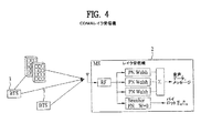
レイク受信機を使用してMS 2が毎フレームごとに上記3つのトラフィックコリレータ(correlator)の結果、または“レイクフィンガー(RAKE finger)”を結合することができる。各レイクフィンガーは、独立して特定PNオフセット及びウォルシュコードを復元できる。探針(searcher)が持続してパイロット信号を検査することによって、各レイクフィンガーは、異なるBTS 3の遅延された多重経路反射をターゲット(targeting)とすることができる。図4に、RAKE受信機の使用を示す。
Using the rake receiver, the
MS 2は、ソフトハンドオフを行うことができる。MS 2は、持続して可能なパイロット信号を検査し、現在見える前記パイロット信号に対してBTS 3に報告する。BTS 3は最大6つのセクターまで割り当て、MS 2はそれによってMSのフィンガーを割り当てる。全てのメッセージはミューティング(muting)無しでディム・アンド・バースト(dim−and−burst)で転送される。各通信リンクの終端は使用者にハンドオフ透明性を提供し、フレームバイフレーム(frame by frame)基盤で最適の構成を選択する。
MS 2は、セット(set)、特に活性セット(Active set)、候補セット(Candidates set)、となりセット(Neighbors set)及び残余セット(Remaining set)内のパイロット信号を考慮する。前記活性セットは、実際使用中であるセクターのパイロット信号を含む。前記候補セットは、MS 2が要請したが、BTS 3による転送がセットアップされていないパイロット信号を含む。前記となりセットは、前記BTS 3によってチェックする隣接セクターと指示されたパイロット信号を含む。前記残余セットは、前記BTS 3によって使用されたが、他のセットによって使用されないいすれのパイロット信号も含む。
The
となりセットまたは残余セット内のパイロット信号が第1臨界値(T_ADD)を超過する時、活性セットパイロット信号が第2臨界値(T_DROP)未満となる時、または、候補パイロット信号が与えられた量だけ活性セットパイロット信号を超過する度に、MS 2はパイロット信号強度測定をBTS 3に転送する。BTS 3は、要請されたハンドオフを全てセットアップしたり、要請されたハンドオフを一部だけ認証するためのスクリーニングカテゴリを適用することができる。
When the pilot signal in the neighbor set or the residual set exceeds the first critical value (T_ADD), when the active set pilot signal becomes less than the second critical value (T_DROP), or by the amount given the candidate pilot signal Each time the active set pilot signal is exceeded,
CDMA2000システムは、第3世代(3G)広帯域システム、すなわち、インターネット及びイントラネット接続、マルチメディアアプリケーション(multimedia application)、高速事業処理及び遠隔測定(telemetry)のようなデータ能力を促進させるためのCDMA技術の改善されたサービス能力を使用する、向上した拡散スペクトラム無線インターフェースシステムである。CDMA2000の目的は、他の3世代システムと同様に、限定された量の無線スペクトラムの制限を克服するためにネットワーク経済及び無線転送デザインを設計することにある。 The CDMA2000 system is a third generation (3G) broadband system, namely CDMA technology to promote data capabilities such as Internet and intranet connections, multimedia applications, high-speed business processing and telemetry. An improved spread spectrum radio interface system that uses improved service capabilities. The purpose of CDMA2000 is to design a network economy and wireless transfer design to overcome the limited amount of radio spectrum limitations, as with other three generation systems.
図5は、CDMA2000無線網のためのデータリンクプロトコル構造階層20を示す。データリンクプロトコル階層20の構造は、上位階層60、リンク階層30及び物理階層21を含む。
FIG. 5 shows a data link
上位階層60は、データサービス副階層61、音声サービス副階層62及びシグナリングサービス副階層63の3つの副階層を含む。データサービス副階層61は、移動端末使用者の側面でいずれの形式のデータも提供し、IPサービスのようなパケットデータアプリケーション、同期ファックスのような回線データアプリケーション及びB−ISDNエミュレーション(emulation)サービス及びSMSを提供する。音声サービス62は、PSTN接続を含み、端末対端末の音声サービス及びインターネット電話を提供する。シグナリングサービス63は、端末動作の全ての側面を制御する。
The
シグナリングサービス副階層63は、MS 2とBS 6間の全てのメッセージ交換を処理する。これらのメッセージは、呼設定及び解除、ハンドオフ、場面活性(feature activation)、システム構成、登録及び認証のような機能を制御する。
The
MS 2で、シグナリングサービス副階層63はまた、呼処理状態、特にMS 2初期化状態、MS 2遊休状態、システム接続状態及びトラフィックチャンネルに対するMS 2制御状態の管理を容易にする。
In
リンク階層30は、リンク接続制御(LAC:Link Access Control)副階層32及び媒体接続制御(MAC:Medium Access Control)副階層31に分けられる。リンク階層30は、プロトコル支援及びデータ転送サービス制御メカニズムを提供し、上位階層60から物理階層21へ特定性能及び特性を転送するのに必要なデータをマッピング(map)するのに必要な機能を行う。リンク階層30は、上位階層60及び物理階層21間のインターフェースといえる。
The
MAC 31及びLAC 32副階層の分離は、広範囲な上位階層60サービスに対する支援要求と広い遂行範囲、特に、1.2Kbpsから2Mbpsを超過する高効率及び低い潜在データサービスを提供しようとする要求によるものである。また、受容できるような遅延及び/またはデータBER(Bit Error Rate)による制限のように、高いQoS(Quality of Service)の回線及びパケットデータサービス提供の必要性及び異なるQoS要求を持つ向上したマルチメディアサービスに対する要求によるものである。
Separation of
LAC副階層32は、点対点無線転送リンク42上で信頼性あり、かつ、インシーケンス(in−sequence)伝達転送制御機能を提供するということが要求される。LAC副階層32は、上位階層60エンティティ間に点対点(point to point)通信チャンネルを管理し、広い範囲の相異なる端対端(end to end)に信頼性あるリンク階層30プロトコルを支援するためのフレームワーク(framework)を提供する。
The
LAC副階層32は、正確なシグナリングメッセージの転送を提供する。LAC副階層が支援する機能には、受信肯定確認が要求される所で保証された伝達、受信肯定確認が要求されない所で保証されなかった伝達、重複メッセージ検出、個別MS 2へのメッセージ伝達のためのアドレス制御、物理媒体上における転送のためにメッセージを適切なサイズの断片に分割すること、グローバルチャレンジ認証(global challenge authentication)及び受信されたメッセージの有効化及び再集合などがある。
The
MAC副階層31は、それぞれの活性サービスに対してQoS管理性能を備えた3G無線システムの複合マルチメディア、マルチサービス性能を活性化させる。MAC副階層31は、パケットデータの接近制御過程を提供し、物理階層(21)に回線データサービスを提供する。また、MAC副階層31は、無線システムで競争中の使用者だけでなく単一使用者からの多重サービス間の衝突制御を含む。MAC副階層31は、論理チャンネルと物理チャンネルのマッピングを行い、多重ソース(source)からのデータを単一物理チャンネル上に多重化、及び信頼性の最善のレベルのために無線リンクプロトコル(RLP)33を使用する無線リンク階層上で合理的で信頼性ある転送を提供する。シグナリング無線バーストプロトコル(SRBP:Signaling Radio Burst Protocol)35は、シグナリングメッセージのための接続のないプロトコルを提供するエンティティである。多重化及びQoS制御34は、競争サービスからの競争される要請などの衝突仲裁による交渉されたQoSレベル、及び接続要請の適切な優先順位施行に関与する。
The
物理階層21は、無線で転送されるデータのコーディング及び変調を行う。物理階層21は、上位階層からのデジタルデータを調節し、移動無線チャンネル上に信頼性あるデータ転送を行う。
The
物理階層21は、MAC副階層31が多重転送チャンネルで伝達した使用者データ及びシグナリングを、物理チャンネルにマッピングさせ、無線インターフェース上で情報を転送する。転送方向で、物理階層21で行われる機能は、チャンネルコーディング、インタリービング、スクランブリング、拡散及び変調などを含む。受信方向で、受信機に伝達されたデータを復元するために前記機能が逆に行われる。
The
図6は、呼処理過程(call processing)の概要を示す。呼処理過程は、パイロット及び同期チャンネル処理過程、ページングチャンネル処理過程、接続チャンネル処理過程及びトラフィックチャンネル処理過程を含む。 FIG. 6 shows an outline of a call processing process (call processing). The call process includes a pilot and sync channel process, a paging channel process, a connection channel process, and a traffic channel process.
パイロット及び同期チャンネル処理過程は、‘MS 2初期化状態’でパイロット及び同期チャンネルを獲得し、CDMAシステムと同期を合わせるMS 2処理過程を指す。ページングチャンネル処理過程は、MS 2が‘遊休状態’でBS 6からオーバーヘッド及び移動端末に向かうメッセージを受信すべく、順方向共通制御チャンネル(F−CCCH:Forward Common Control Channel)またはページングチャンネルをモニタリングすることを指す。接続チャンネル処理過程は、MS 2が‘システム接続状態’で接続チャンネルまたは向上した接続チャンネルを通じてBS 6にメッセージを転送することを指す。この時、BS 6は常にこのようなチャンネルを聴取し、ページングチャンネルまたはF−CCCHのうち一つを用いてMSに応答する。トラフィックチャンネル処理過程は、MS 2とBS 6が‘トラフィックチャンネル状態がMS 2制御’である専用順方向及び逆方向トラフィックチャンネルを用いて通信を行うことを指す。前記専用順方向及び逆方向トラフィックチャンネルは、音声、データのような使用者情報を伝達する。
The pilot and sync channel process refers to an
図7は、MS 2の初期化状態を示す図である。初期化状態は、システム決定副状態、パイロットチャンネル処理状態、同期チャンネル獲得状態、タイミング変更副状態及び移動端末遊休状態を含む。
FIG. 7 is a diagram illustrating an initialization state of the
システム決定副状態は、MS 2がどのシステムからサービスを獲得するかを決定する過程である。システム決定副状態過程は、アナログ対デジタル、セルラー対PCS及びA搬送波対B搬送波のような決定を含む。一般的な選択過程は、システム決定副状態を制御することができる。処理過程を再修正するサービス提供者もまた、システム決定副状態を制御できる。MS 2は、システムを決定した後に、サービス検出のためにシステム内のチャンネルを決定しなければならない。一般的にMS 2は、前記チャンネルを選択するために優先化されたチャンネルリスト(prioritized channel list)を使用する。
The system determination substate is a process in which the
パイロットチャンネル処理過程は、MS 2が使用可能なパイロット信号を検出することによってシステムタイミングに関連した情報を初めて得る過程である。パイロットチャンネルは情報を含んでいないが、MS 2はパイロットチャンネルを相互関連(correlating)させることによって、端末の持つタイミングと整列させることができる。このような相互関連が成立すると、MS 2は同期チャンネルと同期化され、そのタイミングをより細分化して同期チャンネルメッセージを読むことができる。MS 2は失敗を宣言し、他のチャンネルまたは他のシステムのうち一つを選択するためにシステム決定副状態に戻る前に、単一パイロットチャンネルに対して15秒まで検索できる。前記検索手続きでシステムを獲得する時間は具現によって異なり、一般化されていない。
The pilot channel processing process is a process in which
CDMA2000で単一チャンネル上にOTDパイロット、STSパイロット及び付加的なパイロットのような多くのパイロットチャンネルが存在することができる。システム獲得の間にMS 2はこのようなパイロットチャンネルが異なるウォルシュコードを使用するので、このようなパイロットチャンネルを探すことができなく、MS 2は単にウォルシュコード(Walsh 0)に対するものしか検索できない。
There can be many pilot channels such as OTD pilot, STS pilot and additional pilot on a single channel in CDMA2000. During system acquisition,
同期チャンネルメッセージは持続して同期チャンネル上で転送され、MS 2にタイミングを細分化するための情報及びページングチャンネルを読むことのできる情報を提供する。移動端末は、BS 6からの前記同期チャンネルメッセージでBS 6と通信が行えるか否かを決定できる情報を受信する。
The sync channel message is continuously transferred on the sync channel and provides the
CDMA2000メッセージはIS−95 MS 2と逆互換可能である。例えば、前記同期チャンネルメッセージの最初の13フィールドは、IS−95に規定されたものと同一である。IS−95 MS 2が同期チャンネルを獲得した場合、前記端末は、最初の13フィールドのみを調べ、残りのフィールドを無視する。
CDMA2000 messages are backward compatible with IS-95
新しいCDMA2000フィールドは前記IS−95互換フィールド以降に生成される。新しいCDMA2000フィールドは、TDとノン−TDモードに対する拡散率1放送制御チャンネル(BCCH)及び拡散率3BCCH及びパイロットチャンネルに対するパラメータを特定する。
A new CDMA2000 field is generated after the IS-95 compatible field. The new CDMA2000 field specifies parameters for spreading
図8は、CDMA2000システム接続状態を示す図である。システム接続処理過程の1番目の段階は、MS 2が初期電力レベル及び電力段階増加のような正しい接続チャンネルパラメータを使用するかを確認するためのオーバーヘッド情報を更新する。MS 2は、BS 6または他のMSと調整(coordination)無しで無作為に接続チャンネルを選択して転送を始める。このようなランダム接続過程は衝突を招く恐れがある。このような衝突可能性は、スロット化された構造の使用、多重接続チャンネルの使用、無作為的な開始時刻での転送及びオーバーノード部分における混雑制御(congestion control)の適用のような様々な方法を用いて減少されることができる。
FIG. 8 is a diagram illustrating a CDMA2000 system connection state. The first stage of the system connection process updates the overhead information to confirm that
MS 2は、接続チャンネル上に要請または応答メッセージのいずれかを転送することができる。要請メッセージは、開始メッセージ(Origination message)のように独自的に(autonomously)転送されるメッセージである。応答メッセージは、BS 6から受信したメッセージに対する応答として転送されるメッセージである。例えば、ページ応答メッセージは、一般的なページメッセージまたはユニバーサルメッセージに対する応答である。
図9は、移動トラフィックチャンネル状態を示す。この移動トラフィックチャンネル状態は、サービス交渉(Service Negotiation)、活性モード(Active Mode)及びコントロールホールドモード(Control Hold Mode)を含む。 FIG. 9 shows mobile traffic channel conditions. The mobile traffic channel state includes a service negotiation, an active mode, and a control hold mode.
サービス交渉は、MS 2とBS 6が、呼の間にどんなサービスオプションを使用し、該サービスを支援するために無線チャンネルをどのように構成するかを交渉する過程である。通常、サービス交渉は、呼の初期に発生するが、必要な場合には、呼の進行中にも任意に発生することができる。
Service negotiation is the process by which
トラフィックチャンネル副状態で動作する間に、MS 2は活性モードまたはコントロールホールドモードで動作可能である。活性モードで、逆方向パイロットチャンネルは活性であり、高速データを使用可能な場合、R−FCH、R−DCCH、R−SCHまたはR−PDCHも共に活性でありうる。コントロールホールドモードで、逆方向パイロットチャンネルのみが転送され、転送電力を減少させるために1/2または1/4のようなゲートモード(gated mode)で動作できる。
While operating in the traffic channel sub-state, the
図10は、多重化及びQoS制御副階層34の転送機能を示す。データブロックは、同一サービスまたはシグナリングに属するデータブロックである。MuxPDUは、MuxSDU及びヘッダである。このヘッダは、前記シグナリングを主または副として特定する。前記MuxPDUタイプは、レートセットと前記MuxPDUをどのようにパーシング(parse)するかを決定する。前記Muxオプションは、SCH上でのMuxPDU最大数、シングルサイズまたはダブルサイズMuxPDUs及びMuxPDUタイプを決定する。LTUはCRCで保護された1、2、4または8MuxPDUを含む。
FIG. 10 shows the transfer function of the multiplexing and
多重化及びQoS制御副階層34は、物理階層21と時間同期の下に動作する。もし、物理階層21が‘0’でないフレームオフセットで転送すると、多重化及びQoS制御副階層34は、システム時間から適切なフレームオフセットで物理階層が転送するように物理階層SDUを伝達する。
The multiplexing and
多重化及びQoS制御副階層34は、物理チャンネル特定サービスインターフェースプリミティブセットを用いて物理階層21に物理階層SDUを転送する。物理階層21は、物理チャンネル特定受信指示サービスインターフェース動作を用いて物理階層SDUを多重化及びQoS制御副階層34に伝達する。
The multiplexing and
SRBP副階層35は、同期チャンネル順方向共通制御チャンネル、放送制御チャンネル、ページングチャンネル及び接続チャンネル処理手順を含む。 The SRBP sub-layer 35 includes a synchronization channel forward common control channel, a broadcast control channel, a paging channel, and a connection channel processing procedure.
LAC副階層32は、第3階層60にサービスを提供する。SDUは、第3階層60及びLAC副階層32間で伝達される。LAC副階層32は、SDUをLAC PDUに適切にカプセル化(encapsulation)し、これは分割及び再結合されてカプセル化したPDU断片としてMAC副階層31に伝達される。
The
LAC副階層32での処理過程は、処理エンティティがよく設定された順序によってお互い部分的に形成されたLAC PDUを伝達することによって順次に行われる。上位階層は物理チャンネルの無線特性に対して認識する必要がなく、SDU及びPDUは関数的経路に沿って処理されて転送される。しかし、上位階層は物理チャンネルの特性を認識でき、第2階層30が特定PDUの転送に特定物理チャンネルを使用するように指示することができる。
The processing process in the
1xEV−DOシステムは、パケットデータサービスに対して最適化されたサービスであり、データ専用またはデータ最適化(Data Only or Data Optimized;DO)のための単一1.25MHz搬送波(“1x”)で特徴付けられる。なお、ピークデータ率は順方向リンクで4.91512Mbpsであり、逆方向リンクで1.8432Mbpsである。また、1xEV−DOシステムは、分割された周波数バンド及び1xシステム相互ネットワーキング(internetworking)を提供する。 The 1xEV-DO system is a service optimized for packet data services, with a single 1.25 MHz carrier ("1x") for data-only or data-optimized (DO). Characterized. Note that the peak data rate is 4.91512 Mbps on the forward link and 1.8432 Mbps on the reverse link. The 1xEV-DO system also provides a divided frequency band and 1x system internetworking.
CDMA2000は、現在音声及びデータが実際的に最大614.4kbps及び307.2kbpsのデータ率で共に転送されるサービスを提供する。MS 2は、音声呼(voice call)のためにMCS 5と、データ呼(data call)のためにPDSN 12と通信を行う。CDMA2000システムは、ウォルシュコードで区分された順方向転送チャンネルで可変的電力の固定されたレート(rate)で特徴付けられる。
CDMA2000 provides a service in which current voice and data are actually transferred together at data rates of up to 614.4 kbps and 307.2 kbps.
1xEV−DOシステムにおいて最大データ率は2.4Mbpsまたは3.072Mbpsであり、回線交換基幹網7との通信はない。1xEV−DOシステムは、固定された電力及び時分割多重化された単一順方向チャンネルの可変率(variable rate)で特徴付けられる。 In the 1xEV-DO system, the maximum data rate is 2.4 Mbps or 3.072 Mbps, and there is no communication with the circuit switching backbone network 7. The 1xEV-DO system is characterized by a fixed power and a variable rate of a time division multiplexed single forward channel.
図12は、1xEV−DOシステム構造を示す。1xEV−DOシステムで1フレームは16個のスロット(600スロット/秒)で構成され、26.27msまたは32,768チップ(chips)の区間を持つ。単一スロットは1.6667ms長であり、2048チップで構成される。制御/トラフィックチャンネルは、1スロットに1600チップを有し、パイロットチャンネルは1スロットに192チップを有し、MACチャンネルは1スロットに256チップを有する。1xEV−DOシステムは、チャンネル推定及び時間同期化の単純化及び高速化を促した。 FIG. 12 shows a 1xEV-DO system structure. In the 1xEV-DO system, one frame is composed of 16 slots (600 slots / second) and has a section of 26.27 ms or 32,768 chips (chips). A single slot is 1.6667 ms long and consists of 2048 chips. The control / traffic channel has 1600 chips in one slot, the pilot channel has 192 chips in one slot, and the MAC channel has 256 chips in one slot. The 1xEV-DO system has helped simplify and speed up channel estimation and time synchronization.
図13は、1xEV−DOシステムの物理階層チャンネルを示す。図14は、1xEV−DOシステムのデフォルトプロトコル構造を示す。図15は、1xEV−DOシステムのノン−デフォルトプロトコル構造を示す。 FIG. 13 shows the physical hierarchical channel of the 1xEV-DO system. FIG. 14 shows the default protocol structure of the 1xEV-DO system. FIG. 15 shows the non-default protocol structure of the 1xEV-DO system.
1xEV−DOシステムのセッションと関連した情報は、MS 2(または、接続端末(AT:Access Terminal))とBS 6(または、接続網(AN:Access Network))が無線リンクを通じて使用するプロトコル集合、ユニキャスト接続端末識別子(UATI:Unicast Access Terminal Identifier)、当該無線リンク上でAT及びANにより用いられるプロトコル構造及び現在AT位置推定を含む。 Information related to 1xEV-DO system sessions is a set of protocols used by MS 2 (or Access Terminal (AT)) and BS 6 (or Access Network (AN)) over a radio link, It includes a unicast connected terminal identifier (UATI), a protocol structure used by the AT and AN on the radio link, and a current AT location estimate.
図16は、1xEV−DOセッションの確立を示す。図16に示すように、セッション確立(sessione stablishing)過程は、アドレス構成(address configuration)、連結確立(connection establishment)、セッション構成(session cofiguration)及びキー交換(key exchange)を含む。 FIG. 16 shows the establishment of a 1xEV-DO session. As shown in FIG. 16, the session establishment process includes an address configuration, a connection establishment, a session configuration, and a key exchange.
アドレス構成は、UATI及びサブネットマスクを割り当てるアドレス管理プロトコルを指す。連結確立は、無線リンクを設定する連結階層プロトコルを指す。セッション構成は、全てのプロトコルを構成するセッション構成プロトコルを指す。キー交換は、認証キーを設定する保安階層でのキー交換プロトコルを指す。 Address configuration refers to an address management protocol that assigns UATI and subnet mask. Connection establishment refers to a connection layer protocol for establishing a radio link. The session configuration refers to a session configuration protocol that configures all protocols. Key exchange refers to a key exchange protocol in a security layer for setting an authentication key.
“セッション(session)”は、数時間(基本として54時間)オープンされたAT 2とRNC間の論理的通信リンクを指す。なお、セッションは、PPPセッションが活性化されるまで維持される。セッション情報は、AN 6内のRNCにより制御されて維持される。
“Session” refers to a logical communication link between
連結がオープンされた場合、AT 2に順方向トラフィックチャンネルが割り当てられることができ、逆方向トラフィックチャンネル及び逆方向電力制御チャンネルが割り当てられる。多重連結は、単一セッションの間に発生することができる。1xEV−DOシステムには2つの連結状態、すなわち、クローズド連結(closed connection)とオープン連結(open connenction)がある。 If the connection is opened, AT 2 can be assigned a forward traffic channel and assigned a reverse traffic channel and a reverse power control channel. Multiple concatenation can occur during a single session. There are two connection states in the 1xEV-DO system, that is, a closed connection and an open connection.
クローズド連結は、AT 2にいずれの専用無線−リンク資源も割り当てられず、ATとAN 6間の通信は接続チャンネル及び制御チャンネルを通じて行われる状態を指す。オープン連結は、AT 2に順方向トラフィックチャンネルが割り当てられることができ、逆方向トラフィックチャンネル及び逆方向電力制御チャンネルが割り当てられ、AT 2とAN 6間の通信は、前記割り当てられたチャンネルだけでなく、制御チャンネルを通じて行われる状態を指す。
Closed connection refers to a state in which no dedicated radio-link resources are allocated to
連結階層は、ネットワークの初期獲得、オープン連結及びクローズド連結のセッティング及び通信を管理する。また、連結階層は、オープン連結及びクローズド連結で概略的なAT 2位置を維持し、オープン連結がある場合、AT 2とAN 6間の無線リンクを管理する。また、連結階層は、オープン連結及びクローズド連結を管理し、セッション階層で受信した転送されるべきデータを優先化(prioritize)及びカプセル化(encapsulate)し、優先化されたデータを保安階層に伝達し、保安階層から受信したデータに対してはデカプセル化(decapsulate)を行い、セッション階層に伝達する。
The connection hierarchy manages initial network acquisition, open connection and closed connection settings and communication. In addition, the connection layer maintains an
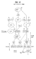
図17は、連結階層プロトコルを示す。図17に示すように、プロトコルは、初期化状態、遊休状態及び連結状態を含む。 FIG. 17 shows a concatenated layer protocol. As shown in FIG. 17, the protocol includes an initialization state, an idle state, and a connection state.
初期化状態で、AT 2はAN 6を獲得し、初期化状態プロトコルを活性化させる。遊休状態で、クローズド連結が開始され、遊休状態プロトコルが活性化される。連結状態で、オープン連結が初期化され、連結状態プロトコルが活性化される。 In the initialization state, AT 2 acquires AN 6 and activates the initialization state protocol. In the idle state, closed connection is initiated and the idle state protocol is activated. In the connected state, the open connection is initialized and the connected state protocol is activated.
初期化状態プロトコルは、AN 6獲得と関連した動作を行う。遊休状態プロトコルは、AN 6は獲得したが、ルートアップデートプロトコルを用いてAT位置を追跡するというようなオープン連結は有しないAT 2と関連した動作を行う。連結状態プロトコルは、AT及びAN 6の無線リンクを管理し、クローズド連結への過程を管理するというようなオープン連結を持つAT 2と関連した動作を行う。ルートアップデートプロトコルはAT 2の位置を追跡し、AT及びAN 6間の無線リンクを維持することと関連した動作を行う。オーバーヘッドメッセージプロトコルは、QuickConfig、SectorParameters及びAccessParametersメッセージのような必須パラメータを、制御チャンネルを通じて放送する。パケット合併プロトコル(Packet Consolidaton Protocol)は、割り当てられた優先順位及びターゲットチャンネルの関数として転送用パケットを合併及び優先化し、受信機に関するパケット逆多重化を提供する。
The initialization state protocol performs operations associated with AN 6 acquisition. The idle state protocol performs operations associated with
1xEV−DO順方向リンクは、支援される電力制御及びソフトハンドオフがないことで特徴付けられる。AN 6は、一定の電力でデータを転送し、AT 2は順方向リンクに可変レートを要請する。TDMで使用者は相異なる時間に転送するので、特定使用者のための相異なるBS 6からのダイバーシティ転送を具現し難い。
The 1xEV-DO forward link is characterized by no power control and soft handoff supported. AN 6 transfers data with constant power, and AT 2 requests a variable rate on the forward link. In TDM, users transfer at different times, so it is difficult to implement diversity transfer from
物理階層は1.2288Mcps拡散率(spreading rate)によって特徴付けられ、、1フレームは16スロット及び26.63msで構成され、1スロットは1.67ms及び2048チップで特定される。順方向リンクチャンネルは、パイロットチャンネル、順方向トラフィックチャンネルまたは制御チャンネル及びMACチャンネルを含む。 The physical layer is characterized by a 1.2288 Mcps spreading rate, where one frame consists of 16 slots and 26.63 ms, and one slot is specified by 1.67 ms and 2048 chips. The forward link channel includes a pilot channel, a forward traffic channel or control channel, and a MAC channel.
前記パイロットチャンネルは、全ての情報ビットが“0”であり、ウォルシュ−拡散コードが1スロットに192チップを持つW0であるという点で、CDMA2000パイロットチャンネルに似ている。 The pilot channel is similar to the CDMA2000 pilot channel in that all information bits are “0” and the Walsh-spreading code is W0 with 192 chips in one slot.
順方向トラフィックチャンネルは38.4kbps〜2.4576Mbps、または、4.8kbps〜3.072Mbpsの範囲で変わるデータ率(data rate)で特徴付けられる。物理階層パケットは、1ないし16スロット内に転送されることができ、前記転送スロットは、一つ以上のスロットが割り当てられた場合に4−スロット(4−slot)インターレーシング(interlacing)を使用する。割り当てられた全てのスロットが転送される前に、逆方向リンクACKチャンネルを通じてACKが受信されると、残ったスロットは転送されない。 The forward traffic channel is characterized by a data rate that varies from 38.4 kbps to 2.4576 Mbps, or from 4.8 kbps to 3.072 Mbps. The physical layer packet can be transferred in 1 to 16 slots, and the transfer slot uses 4-slot interlacing when one or more slots are allocated. . If an ACK is received through the reverse link ACK channel before all assigned slots are transferred, the remaining slots are not transferred.
制御チャンネルは、CDMA2000の同期チャンネル及びページングチャンネルに似ている。制御チャンネルは、256スロットまたは426.67ms周期、1024ビットまたは128,256,512及び1024ビットの物理階層パケット長、及び38.4kbpsまたは76.8kbpsまたは19.2kbpsまたは76.8kbpsのデータ率を特徴とする。 The control channel is similar to the CDMA2000 synchronization channel and paging channel. The control channel features 256 slots or 426.67 ms period, 1024 bit or 128, 256, 512 and 1024 bit physical layer packet length and data rate of 38.4 kbps or 76.8 kbps or 19.2 kbps or 76.8 kbps And
MACチャンネルは、RA(reverse Activity)チャンネル、逆方向電力制御チャンネル、DRCLockチャンネル、ARQチャンネル及びパイロットチャンネルを含む。 The MAC channel includes an RA (Reverse Activity) channel, a reverse power control channel, a DRCLock channel, an ARQ channel, and a pilot channel.
RA(reverse Activity)チャンネルは、AN 2がそのカバレッジ内にある全てのATにDPRP逆方向リンク上の現在活動(activity)について知らせ、MACインデックスが4のMACチャンネルである。RAチャンネルは、ビット率が(600/RABLength)bpsまたは600bpsであるRABLength連続スロット(サブタイプ0、1)を通じてRAB(reverse Activity Bits)を伝達する。
The RA (Reverse Activity) channel is a MAC channel where AN 2 informs all ATs within its coverage about the current activity on the DPRP reverse link and the MAC index is 4. The RA channel transmits RAB (reverse activity bits) through a RABLlength continuous slot (
AN 6は、AT 2の逆方向リンク転送に使用する電力を制御するために逆方向電力制御(RPC)チャンネルを使用する。逆方向電力制御ビットがRPCチャンネルを通じて600(1−1/DRCLockPeriod)bpsまたは150bpsのデータ率で転送される。
AN 6 uses a Reverse Power Control (RPC) channel to control the power used for
DRCLockチャンネルは、セクターが特定ATを聞けない場合に、DRCがAT 2に順方向転送をスケジューリングできず、ATがDRCを通じて持続してサービスを要請する状況を防止する。AT 2に対してDRCLockビットがセッティングされると、前記ATはセクターへのDRC転送を中止する。DRCLockチャンネルデータ率は、600/(DRCLockLength×DRCLockPeriod)bpsまたは(150/DRCLockLength)bpsである。
The DRCLock channel prevents a situation in which the DRC cannot schedule a forward transfer to the
ARQチャンネルは、逆方向リンクハイブリッド−ARQ(H−ARQ)を支援し、これによってAN 6が物理階層パケットを受信した場合に残りの副−パケットが転送されないようにする。H−ARQは、AN 6がスロットm−8、m−7、m−6及びm−5に転送されたパケットを成功的に受信したか否かを示す。 The ARQ channel supports reverse link hybrid-ARQ (H-ARQ), which prevents the remaining sub-packets from being forwarded when AN 6 receives a physical layer packet. H-ARQ indicates whether AN 6 has successfully received packets forwarded to slots m-8, m-7, m-6, and m-5.
DRCチャンネルは、AT 2が、選択されたサービングセクター及び順方向トラフィックチャンネルに対する要請データ率をAN 6に指示するのに用いられる。前記要請データ率は、選択されたサービングセクターに相応するDRCチャンネル転送拡散のための8−アレイウォルシュ関数と一緒に4けた(4−digit)トDRC値にマッピングされる。順方向トラフィックチャンネルMACプロトコルからのDRCCoverは、カバーマッピングを定義する。DRC値は、600/DRCLength DRC値/秒当たりのデータ率で転送され、最大データ率は600/秒で、最小データ率は75/秒である。
The DRC channel is used by
BS 6のスケジューリングは、セクターで具現され、DRCに基づいてAT 2に帯域を割り当てることによってBSがどんな使用者データを次に転送するかを決定するのを促進する。可能なスケジューラはラウンドロビン(Round Robin)、最上速度(Best Rate)及び比例工程(Proportional Fairness)を含む。スケジューラ入力は、DRC、ACK/NAK、QoS及び加入者プロフィール、ヒストリー、トラフィックモデル及びAT容量(capability)を含む。
ラウンドロビンは、基本公正性(basic fairness)を強調する。最上速度は、スループットを強調する。比例工程は、公正性とスループットをバランスさせる。 Round robin emphasizes basic fairness. Top speed emphasizes throughput. The proportional process balances fairness and throughput.
選択された使用者に対するデータ転送は、BS 6が前記報告されたDRCを用いてFLデータ率、変調方式及びコーディング率を決定するのを促進する。ファットパイプスケジューリング(Fat Pipe Scheduling)で、セクター内の全てのAT 2は1.25MHz無線搬送波を共有し、パイプは1.667msスロットに分割され、パケットが一つ以上のスロットを要求する場合、パケット断片が4スロット間隔に転送される。
Data transfer for the selected user facilitates
4−スロットインターレーシングで、物理階層パケットの転送スロットは3つのスロットにより分離され、他の物理階層パケットがこれらの転送スロット間のスロットに転送される。全ての割り当てられたスロットが転送される前にACKチャンネルを通じてACKを受信した場合、転送されずに残っているスロットは転送されない(ハイブリッドARQ)。 In 4-slot interlacing, the transfer slot of the physical layer packet is separated by three slots, and the other physical layer packet is transferred to the slot between these transfer slots. If an ACK is received through the ACK channel before all assigned slots are transferred, the remaining slots that are not transferred are not transferred (hybrid ARQ).
ACK/NAKは、AT 2が一部のデータを受信し、チェックサムを確認するのを促進する。図18は、順方向リンクでのACK/NAK動作を示す。 ACK / NAK facilitates AT 2 to receive some data and verify the checksum. FIG. 18 shows ACK / NAK operation on the forward link.
AT 2は、ACKチャンネルを用いてAN 6に順方向トラフィックチャンネルに転送された物理階層パケットが成功的に受信されたかを知らせる。特に、0にセッティングされたACKビットはCRC OKを表し、1にセッティングされたACKビットはCRC Failを表す。図18は、逆方向リンクでのACKチャンネル使用を示す。 AT 2 informs AN 6 using the ACK channel whether the physical layer packet forwarded to the forward traffic channel has been successfully received. In particular, the ACK bits setting to zero represents CR C OK, the ACK bits setting in 1 represents a CRC Fail. FIG. 18 shows ACK channel usage on the reverse link.
より広い帯域幅を持つ新しいセルラー通信システムが現在開発されつつある。例えば、現在3GPP、3GPP2及びIEEE802.20無線インターフェースは、20MHzまでのスペクトラム割当を目標としている。未来のシステムは100MHzまで収容可能になるはずである。これは、根本的に、より大きいエンドユーザー情報転送率及びQoS(Quality of service)に対する一般的な欲求から動機付けられた。 New cellular communication systems with wider bandwidth are currently being developed. For example, currently 3GPP, 3GPP2 and IEEE 802.20 wireless interfaces are targeted for spectrum allocation up to 20 MHz. Future systems should be able to accommodate up to 100 MHz. This was fundamentally motivated by the greater end-user information transfer rate and the general desire for quality of service (QoS).
上記のようなシステムを設計する上での多くの課題のうちの一つは、データ率、レイテンシ、パケットエラー率及びジターのような様々なQoS要件を備えた多様なトラフィックアプリケーションを支援することである。例えば、低いレイテンシ及び低いレート(rate)を要求するVoIP使用者のQoS要件は、より寛大なレイテンシ及びより大きいレートを要求するウェブブラウジング使用者のQoS要件とバランスしなければならない。 One of the many challenges in designing such a system is to support various traffic applications with various QoS requirements such as data rate, latency, packet error rate and jitter. is there. For example, the QoS requirements of VoIP users who require low latencies and low rates must be balanced with the QoS requirements of web browsing users who require more generous latencies and higher rates.
また、All−IPネットワークに対する一般的な傾向を考慮すると、広範囲なトラフィックタイプを支援する必要がある。例えば、VoIP使用者は、低いレイテンシを引き起こす多重接続を要求するのに対し、ウェブブラウジング使用者は機会的スケジューリングを許容する多重接続方法を要求することができる(例、転送が“良い”フェード(fade)間にスケジューリングされ、“悪い”フェーズ間にスケジューリングされない)。 Also, considering the general trend for All-IP networks, it is necessary to support a wide range of traffic types. For example, a VoIP user may require multiple connections that cause low latency, while a web browsing user may request multiple connection methods that allow for occasional scheduling (eg, fades with “good” forwarding ( scheduled during fade) and not scheduled during the "bad" phase).
もう一つの課題は、各使用者が経験するチャンネル条件に適合する無線インターフェースを設計することである。例えば、高い受信SNRを持つ使用者にはOFDM/OFDMAが適合しているのに対し、帯域幅拡張因子のような処理利得が必要な低い受信SNRを持つ使用者にはMC−CDMAが適合している。 Another challenge is to design a wireless interface that matches the channel conditions experienced by each user. For example, OFDM / OFDMA is suitable for a user with a high reception SNR, whereas MC-CDMA is suitable for a user with a low reception SNR that requires a processing gain such as a bandwidth expansion factor. ing.
したがって、転送システムは、多様なトラフィックQoS要件及び多様なチャンネル条件を支援しなければならない。また、従来のサービングセル交換は、HPRDの64−スロットDSC構成におけると同様に、3G無線システムで遅い方であり、あるセルから他のセルへのデータ伝達は、セル交換遅延の主要原因となる。 Therefore, the forwarding system must support various traffic QoS requirements and various channel conditions. Also, conventional serving cell switching is slower in 3G wireless systems, as in the HPRD 64-slot DSC configuration, and data transfer from one cell to another is a major cause of cell switching delay.
本発明の特徴と利点は明細書に記載され、部分的には明細書の記載から明白になり、さらには本発明の実施から明らかになることができる。本発明の目的及び他の利点は、詳細な説明、特許請求の範囲及び添付の図面によって具体的に指示された構造から具現されたり確認されることができる。 The features and advantages of the invention will be set forth in the specification and in part will be apparent from the description, and may further be apparent from practice of the invention. The objectives and other advantages of the invention may be realized and attained from the structure particularly pointed out in the written description and claims hereof as well as the appended drawings.
本発明は、OFDM、OFDMA、単一搬送波FDMA及び/またはMC−CDMAまたは転送基本方式として離散トーンまたは正弦波を用いる任意のシステムの組合せに基づく、多重使用者を支援するセルラー通信システムの多重接続設計に関する。 The present invention relates to multiple connections in a cellular communication system supporting multiple users based on a combination of OFDM, OFDMA, single carrier FDMA and / or MC-CDMA or any system using discrete tones or sinusoids as the transport basis. Regarding design.
本発明の一様相で、ARQを使用する移動通信システムにおいてそれぞれ複数のサブパケットを含む第1データパケット及び第2データパケットを、それぞれ第1端末及び第2端末に提供する方法が提供される。前記方法は、前記第1データパケットを前記第1端末に転送する段階と、前記第2データパケットを前記第2端末に転送する段階と、を含み、前記第1データパケットの複数のサブパケットを全て送信する前にACKが受信された場合、前記第2データパケットの複数のサブパケットのうち少なくとも一つは転送される状態で残っているように、前記第2データパケットの1番目のサブパケットが前記第1データパケットの1番目のサブパケットよりも遅延される。 In one aspect of the present invention, a method for providing a first data packet and a second data packet each including a plurality of subpackets to a first terminal and a second terminal in a mobile communication system using ARQ is provided. The method includes: transferring the first data packet to the first terminal; and transferring the second data packet to the second terminal, wherein a plurality of subpackets of the first data packet are transmitted. The first sub-packet of the second data packet, so that if at least one of the plurality of sub-packets of the second data packet remains in a transferred state when an ACK is received before all transmission Is delayed from the first subpacket of the first data packet.
前記第1データパケットの複数のサブパケット及び前記第2データパケットの複数のサブパケットは、スロット転送方式によって少なくとも一つの未使用転送スロットが第1及び第2データパケットのそれぞれの複数のサブパケットにおいて各サブパケットの間に存在するように転送されることができる。また、前記第1データパケットの複数のサブパケットはそれぞれ、前記第2データパケットの複数のサブパケットのうち、対応するサブパケットと略同時に転送されることができる。好ましくは、前記移動通信システムはMC−CDMAを含む。 The plurality of sub-packets of the first data packet and the plurality of sub-packets of the second data packet may include at least one unused transfer slot in each of the plurality of sub-packets of the first and second data packets according to a slot transfer method. It can be forwarded to exist between each subpacket. In addition, each of the plurality of subpackets of the first data packet may be transferred substantially simultaneously with the corresponding subpacket among the plurality of subpackets of the second data packet. Preferably, the mobile communication system includes MC-CDMA.
本発明の他の様相で、信号転送のために離散トーンを使用する多重接続移動通信システムでにおいて複数の使用者に複数の多重接続技法を提供する方法が提供される。前記方法は、前記複数の多重接続技法を定義(defining)する段階と、前記複数の使用者に対する通信要件を決定する段階と、前記複数の使用者のそれぞれに前記複数の定義された多重接続技法のうちの一つを割り当てる段階と、前記複数の使用者の数、前記複数の使用者のそれぞれの電力要件、前記複数の使用者のそれぞれに対する音声通話率要件及び前記移動通信システムのアンテナ数のうち少なくとも一つによって前記離散トーンを時間領域で前記複数の使用者にパーティショニング(partitioning)する段階と、を含む。 In another aspect of the invention, a method is provided for providing multiple multiple access techniques to multiple users in a multiple access mobile communication system that uses discrete tones for signal transfer. The method comprises: defining the plurality of multiple access techniques; determining communication requirements for the plurality of users; and defining the plurality of defined multiple access techniques for each of the plurality of users. Assigning one of: a number of the plurality of users, a power requirement of each of the plurality of users, a voice call rate requirement for each of the plurality of users, and a number of antennas of the mobile communication system Partitioning the discrete tones to the plurality of users in a time domain by at least one of them.
前記パーティショニングは、複数の基地局及びセルセクターのうち少なくとも一つで同期することができる。また、前記パーティショニングに関する指示情報を、周期的にまたは前記パーティショニングが変更された場合に、放送メッセージを介して前記複数の使用者に提供することをさらに含むことができる。 The partitioning may be synchronized with at least one of a plurality of base stations and cell sectors. In addition, it may further include providing instruction information related to the partitioning to the plurality of users via a broadcast message periodically or when the partitioning is changed.
前記複数の技法は、MC−CDMAを含み、MC−CDMAに割り当てられた前記複数の使用者の数によって拡散コード長を異ならせることをさらに含むことができる。また、ARQが支援され、前記複数の使用者のうち少なくとも一つの使用者に対する第1データパケットの1番目のサブパケット転送を、前記複数の使用者のうち少なくとも一つの第2使用者に対するデータパケットの第2サブパケットの1番目のサブパケットに対して相対的に遅延させることによって、前記離散トーンを時間領域でパーティショニングすることをさらに含むことができる。 The plurality of techniques may include MC-CDMA, and may further include varying a spreading code length according to a number of the plurality of users assigned to MC-CDMA. Also, ARQ is supported, and the first subpacket transfer of the first data packet for at least one user among the plurality of users is performed, and the data packet for at least one second user among the plurality of users is transmitted. Partitioning the discrete tones in the time domain by delaying relative to the first subpacket of the second subpacket.
本発明の他の様相で、移動通信システムにおいて端末に制御情報を提供する方法が提供される。前記方法は、複数の連続(consecutive)フィールドを含む制御メッセージを前記端末に転送する段階を含み、前記複数の連続フィールドがそれぞれの連続フィールドを含むか否かは少なくとも一つの値及び複数の連続フィールドに少なくとも一つの先行する連続フィールドが含まれたか否かに依存することによって、前記複数の連続フィールドから第1連続フィールドを抽出することによって前記複数の連続フィールドから少なくとも一つの第2連続フィールドを抽出するようにし、前記メッセージの長さを減少させることができる。 In another aspect of the present invention, a method for providing control information to a terminal in a mobile communication system is provided. The method includes the step of transferring a control message including a plurality of consecutive fields to the terminal, wherein whether or not the plurality of consecutive fields include a respective consecutive field includes at least one value and a plurality of consecutive fields. Extracting at least one second continuous field from the plurality of consecutive fields by extracting a first continuous field from the plurality of consecutive fields by depending on whether or not includes at least one preceding continuous field Thus, the length of the message can be reduced.
前記メッセージはTCAメッセージでありうる。また、前記複数の連続フィールドは、NumUniqueTrafficMACIndexes、SchedulerTag、AuxDRCCoverIncluded及びAuxDRCCoverのうち少なくとも2つを含むことができる。好ましくは、前記TCAメッセージは、SectorInThisFrequencyIncluded、PilotCarriesPilotChannel、GroupID、NumUniqueTrafficMACIndexes、SchedulerTag、AuxDRCCoverIncluded及びAuxDRCCoverを含む。 The message may be a TCA message. The plurality of continuous fields may include at least two of NumUniqueTrafficMACIndex, SchedulerTag, AuxDRCCoverIncluded, and AuxDRCCover. Preferably, the TCA message includes SectorInThisFrequencyIncluded, PilotCarriersPilotChannel, GroupID, NumUniqueTrafficMACIndex, SchedulerTag, AuxDRCCoverInclude, and AuxDRCCoverInclude.
本発明の他の様相で、移動端末が提供される。前記移動端末は、複数の連続フィールドを含む制御メッセージを受信する送/受信ユニットと、使用者インターフェース情報をディスプレイするディスプレイユニットと、使用者データを入力する入力ユニットと、前記複数の連続フィールドから第1連続フィールドが抽出されたと判断された場合、前記複数の連続フィールドで少なくとも一つの第2連続フィールドが処理されないように前記制御メッセージを処理するプロセシングユニットと、を含む
前記メッセージは、TCAメッセージでありうる。前記複数の連続フィールドは、NumUniqueTrafficMACIndexes、SchedulerTag、AuxDRCCoverIncluded及びAuxDRCCoverのうち少なくとも2つを含むことができる。好ましく、TCAメッセージは、SectorInThisFrequencyIncluded、PilotCarriesPilotChannel、GroupID、NumUniqueTrafficMACIndexes、SchedulerTag、AuxDRCCoverIncluded及びAuxDRCCoverを含む。
In another aspect of the invention, a mobile terminal is provided. The mobile terminal includes a transmission / reception unit that receives a control message including a plurality of continuous fields, a display unit that displays user interface information, an input unit that inputs user data, and a plurality of continuous fields. A processing unit that processes the control message such that at least one second continuous field is not processed in the plurality of continuous fields when it is determined that one continuous field has been extracted. The message is a TCA message. sell. The plurality of continuous fields may include at least two of NumUniqueTrafficMACIndex, SchedulerTag, AuxDRCCoverIncluded, and AuxDRCCover. Preferably, the TCA message includes SectorInThisFrequencyIncluded, PilotCarriesPilotChannel, GroupID, NumUniqueTrafficMACIndex, SchedulerTag, AuxDRCCoverInclude, and AuxDRCCov.
本発明の追加的な特徴と利点は明細書に記載され、部分的には明細書の記載から明白になり、さらには本発明の実施から理解されることができる。本発明に関する一般的な説明及び詳細な説明は例示的なもので、請求された発明をさらに説明するためのものである。 Additional features and advantages of the invention will be set forth in the specification and will be in part apparent from the description, and may be further understood from practice of the invention. The general description and detailed description of the invention is exemplary and is intended to further illustrate the claimed invention.
また、明細書に記載された実施例の他にも、添付の図面を参照して詳細に説明された実施例に基づく様々な改変例が可能であるということは、当業者にとっては明らかであり、したがって、本発明は、開示された特定実施例に限定されることはない。 In addition to the embodiments described in the specification, it is obvious to those skilled in the art that various modifications based on the embodiments described in detail with reference to the accompanying drawings are possible. Thus, the present invention is not limited to the specific embodiments disclosed.
以下、本発明の好適な実施例を、添付の図面を参照しつつ詳細に説明する。本発明は、多様なトラフィックQoS要求及び多様なチャンネル条件を支援できる柔軟な離散トーン基盤無線インターフェースを生成することによって、多様なトラフィックQoS要件及び多様なチャンネル条件を支援する転送方法に関するものである。 Hereinafter, preferred embodiments of the present invention will be described in detail with reference to the accompanying drawings. The present invention relates to a transfer method for supporting various traffic QoS requirements and various channel conditions by generating a flexible discrete tone based wireless interface capable of supporting various traffic QoS requirements and various channel conditions.
本発明の一実施例で、時間−周波数資源は、複数のグループにパーティショニングされる。各グループは、時間−周波数領域で連結されたり連結されなかった離散トーンセットを含む。グループは、離散トーンに基盤する多重接続方法のうちの一つを用いることができる。 In one embodiment of the present invention, time-frequency resources are partitioned into multiple groups. Each group includes discrete tone sets that are connected or not connected in the time-frequency domain. The group can use one of multiple access methods based on discrete tones.
パーティショニングは、様々な方法で行うことができる。周波数−ワイズ(frequency−wise)パーティショニングは、隣接グループ、インターレーシングした非隣接グループ、隣接及び非隣接グループの組合せを用いて行うことができる。時間−ワイズ(time−wise)パーティショニングは、隣接グループ、インターレーシングした非隣接グループ、隣接及び非隣接グループの組合せを用いて行うことができる。一般化された時間−周波数パーティショニングは、周波数−ワイズパーティショニング及び時間−ワイズパーティショニングの任意の組合せを用いて行うことができる。 Partitioning can be done in various ways. Frequency-wise partitioning can be performed using adjacent groups, interlaced non-adjacent groups, and combinations of adjacent and non-adjacent groups. Time-wise partitioning can be performed using adjacent groups, interlaced non-adjacent groups, and combinations of adjacent and non-adjacent groups. Generalized time-frequency partitioning can be performed using any combination of frequency-wise partitioning and time-wise partitioning.
説明を簡略にするために、本発明による実施例は、OFDM及びMC−CDMAに関して説明する。ただし、OFDMをOFDMAに、MC−CDMAを単一搬送波FDMAに取って代わることができる。 For simplicity of explanation, embodiments according to the present invention will be described with respect to OFDM and MC-CDMA. However, OFDM can be replaced by OFDMA and MC-CDMA can be replaced by single carrier FDMA.
例えば、システムは、二つのグループ、すなわち、OFDMを使用するグループとMC−CDMAを使用するグループを持つことができる。VoIP(Voice Over Internet Protocol)使用者は、MC−CDMAグループに割り当てられることができる反面、ウェブブラウジング使用者は、OFDMグループに割り当てられることができる。 For example, the system may have two groups: a group that uses OFDM and a group that uses MC-CDMA. VoIP (Voice Over Internet Protocol) users can be assigned to MC-CDMA groups, while web browsing users can be assigned to OFDM groups.
また、使用者がシステムに出入するので、前記パーティショニングは、時間によって変わることができる。例えば、使用者がVoIPを優勢に使用するとしたら、より多くの帯域幅(時間及び/または周波数)がVoIPに割り当てられることができる。一方、使用者がOFDMを優勢に使用するとしたら、より多くの帯域幅(時間及び/または周波数)がOFDMに割り当てられることができる。 Also, as the user enters and exits the system, the partitioning can vary with time. For example, if the user prefers to use VoIP, more bandwidth (time and / or frequency) can be allocated to VoIP. On the other hand, if the user prefers to use OFDM, more bandwidth (time and / or frequency) can be allocated to OFDM.
セルラー環境で、前記パーティショニングはまた、基地局及びセクター間で同期されたり独立して行われることができる。同期され、ユニバーサル周波数再使用を使用するとしたら、同一周波数ソフトハンドオフ(SHO)を用いて、多重セクター及び/または基地局が同一にまたは異なってコーディングされた同一情報を転送することができる。相異なる周波数SHOは、同一情報が異なる送信機から異なる周波数を通じて転送されるノン−ユニバーサル周波数再使用システムに用いられることができる。 In a cellular environment, the partitioning can also be synchronized or performed independently between the base station and the sector. If synchronized and universal frequency reuse is used, multiple sectors and / or base stations can transmit the same information coded the same or different using same frequency soft handoff (SHO). Different frequencies SHO can be used in non-universal frequency reuse systems where the same information is transferred from different transmitters through different frequencies.
トラフィック要求によってセクターの間で可変パーティショニングが行われることができる。前記パーティショニングは、周期的にまたはパーティショニングが変更された場合に、放送メッセージを通じて指示されることができる。前記放送メッセージは、インバンド(in−band)またはMACメッセージのための上位階層メッセージでありうる。 Variable partitioning can be performed between sectors according to traffic requirements. The partitioning may be directed through a broadcast message periodically or when the partitioning is changed. The broadcast message may be an upper layer message for in-band or MAC message.
MC−CDMAコードの長さは、資源の量及びMC−CDMA使用者数が可変的であるため変動されることができる。例えば、MC−CDMAは、資源の量が多い場合にウォルシュハダマドコードのような長さ64コードを用いることができる。一方、資源の量が少ない場合には、長さ8シーケンスが用いられることができる。好ましくは、複数の離散トーンで1、2、4、8、16及び32のようにいろいろな長さを持つウォルシュハダマドコードが用いられる。 The length of the MC-CDMA code can be varied because the amount of resources and the number of MC-CDMA users are variable. For example, MC-CDMA can use a length 64 code such as Walsh Hadamard code when the amount of resources is large. On the other hand, if the amount of resources is small, a length 8 sequence can be used. Preferably, Walsh Hadamard codes having various lengths such as 1, 2, 4, 8, 16, and 32 are used for a plurality of discrete tones.
典型的に、MC−CDMAは、1時間スロットで16個のトーンを使用する16長ウォルシュコードと同様に、同一時間スロットに制限される。MC−CDMAコードはまた、4個のトーンを1時間スロットに使用し、他の4個のトーンを他の時間スロットに使用する16長ウォルシュコードと同様にに、時間領域に分散されることができる。 Typically, MC-CDMA is limited to the same time slot, as is a 16-length Walsh code that uses 16 tones in one time slot. The MC-CDMA code may also be distributed in the time domain, similar to a 16-length Walsh code that uses 4 tones in one time slot and the other 4 tones in other time slots. it can.
多重MC−CDMAグループが用いられることができる。しかし、音声活動に対して多重化利得を最大にするために、単一MC−CDMAグループが好ましく用いられる。 Multiple MC-CDMA groups can be used. However, a single MC-CDMA group is preferably used to maximize the multiplexing gain for voice activity.
多重アンテナが存在する場合、多重転送アンテナが用いられることができる。パーティショニングが追加的に時間、周波数及びアンテナ(空間)領域にパーティショニングされることができるという点から、3次元パーティショニングが生成されることができる。パーティショニングは、アンテナに対して一定(consistent)したり異なることができる。 When multiple antennas are present, multiple transfer antennas can be used. Three-dimensional partitioning can be generated in that the partitioning can additionally be partitioned into time, frequency and antenna (spatial) domains. Partitioning can be consistent or different with respect to the antenna.
複数の多重化技法または多重接続技法が用いられることができる。例えば、OFDM使用者は、CQI(channel quality information)フィードバックを用いてレート制御(rate−control)、またはリンク順応(link adaptation)をすることができる。一方、MC−CDMA使用者は、使用者別電力レベルが、CQIまたは電力制御ビット命令のように、相対的に細密でないフィードバックを使用するIS−20001xRTTのような方式によって個別的に調節されるように電力制御を行うことができる。 Multiple multiplexing techniques or multiple access techniques may be used. For example, an OFDM user can perform rate-control or link adaptation using CQI (channel quality information) feedback. On the other hand, MC-CDMA users can individually adjust their power level according to a method such as IS-20001xRTT using relatively fine feedback such as CQI or power control bit command. It is possible to perform power control.
電力制御は、各送信機またはセクターに一つの命令が存在するようにフィードバックリンク上の単一制御命令ビットまたは多重命令を用いて行われることができる。基地局の近くにいるMC−CDMA使用者は電力を少なく要求するのに対し、遠くにいる使用者はより多くの電力を要求する。 Power control can be performed using a single control command bit or multiple commands on the feedback link such that there is one command for each transmitter or sector. MC-CDMA users near the base station require less power, while users far away require more power.
MC−CDMAは、音声フレームが1/8(または、ナル)、1/4、1/2またはフルレート音声フレームであるので、多様な音声活動を受容するように設計されることができる。例えば、長さ64コードを持つ現在のIS−2000が用いられることができる。また、現存のIS−2000は、トラフィック要求変更によってより短かいか長いコード長を持つように変更されることができる。 MC-CDMA can be designed to accept a variety of voice activities since the voice frames are 1/8 (or null), 1/4, 1/2 or full rate voice frames. For example, the current IS-2000 with a length 64 code can be used. Also, the existing IS-2000 can be modified to have a shorter or longer code length by changing traffic requirements.
相異なるセクターが同一MC−CDMAグループまたは異なるグループに同一情報を転送することができる。OFDMと同様に、セクター交換によってマルチサイトダイバーシティが可能である。 Different sectors can transfer the same information to the same MC-CDMA group or different groups. Similar to OFDM, multi-site diversity is possible by sector exchange.
MC−CDMA及びOFDMはいずれもARQを支援することができる。例えば、CDMA2000 Rev.C内の全てのMC−CDMA使用者は、1.666msecスロットが与えられた場合、二回、または4スロットごとに転送するようにしたインターレース内で設定された回数だけ再転送するようにセッティングされることができる。 Both MC-CDMA and OFDM can support ARQ. For example, CDMA2000 Rev. All MC-CDMA users in C are set to retransmit a set number of times in an interlace that is intended to transfer twice or every four slots given a 1.666 msec slot. Can.
再転送インスタント(instants)は、多重セクター送信機が使われた場合、ソフト結合(soft−combining)を許容するようにプリセットされる。例えば、20msecをカバーする1つのインターレース内の連続した3スロットは、最大2つのサブパケット再転送を許容する。 Retransmit instants are preset to allow soft-combining when a multi-sector transmitter is used. For example, three consecutive slots in one interlace covering 20 msec allow a maximum of two subpacket retransmissions.
端末は、パケットを正常にデコーディングすると、ACKを転送する。ACKをデコーディングしたセクターは、以降転送を中断することができる。ACKデコーディングに失敗したセクターは再転送されることができる。 When the terminal successfully decodes the packet, the terminal transmits an ACK. The sector in which ACK is decoded can suspend transmission thereafter. Sectors that fail ACK decoding can be retransmitted.
MC−CDMA使用者は、使用者同士間で1番目のサブパケットの転送時間が、時間領域で分散されるようにスタガー(stagger)されることができる。こういう方式で、資源が均等に割り当てられることができる。例えば、VoIP使用者はACKが速く受信されると速く終了されることができるので、より多くの資源が以降のMC−CDMAによるサブパケット再転送に用いられることができる。また、全ての初期MC−CDMAサブパケットを整列することも可能である。 MC-CDMA users can be staggered so that the transfer time of the first subpacket between users is distributed in the time domain. In this way, resources can be allocated evenly. For example, since a VoIP user can be terminated quickly if an ACK is received quickly, more resources can be used for subsequent sub-packet retransmission by MC-CDMA. It is also possible to align all initial MC-CDMA subpackets.
本明細書では開示内容が主にセルラー通信システムの順方向リンクに適用されたが、本開示内容は逆方向リンクに適用されても良く、また、放送及びマルチキャストのような単一リンクシステムに適用されても良い。また、本開示内容は、TDDシステムに適用されても良い。 Although the disclosure herein has been primarily applied to the forward link of cellular communication systems, the disclosure may be applied to the reverse link and also to single link systems such as broadcast and multicast. May be. In addition, the present disclosure may be applied to a TDD system.
図19〜図23は、16個のトーン及び8個の時間スロット、または8シンボル/列を持つシステムでのパーティショニング例を示す。x軸は時間を表し、y軸は周波数を表す。各セルは、離散トーンシンボルを表す。 FIGS. 19-23 show examples of partitioning in a system with 16 tones and 8 time slots, or 8 symbols / sequence. The x-axis represents time and the y-axis represents frequency. Each cell represents a discrete tone symbol.
図19は、全てMC−CDMAトラフィックである例を示す。図20は、全てOFDMトラフィックである例を示す。図21は、周波数領域にのみ均等にパーティショニングされたVoIP及びウェブブラウジングトラフィックを示す。図22は、周波数領域にのみパーティショニングされた少ないVoIPトラフィック及びより多くのウェブブラウジングトラフィックを示す。図23は時間及び周波数領域の両方にパーティショニングされた少ない数のVoIP使用者を示す。 FIG. 19 shows an example of all MC-CDMA traffic. FIG. 20 shows an example of all OFDM traffic. FIG. 21 shows VoIP and web browsing traffic evenly partitioned only in the frequency domain. FIG. 22 shows less VoIP traffic and more web browsing traffic partitioned only in the frequency domain. FIG. 23 shows a small number of VoIP users partitioned in both time and frequency domain.
図24は、2人のVoIP使用者として‘S’及び‘R’を持つMC−CDMAにおけるARQ動作を示す。x軸は時間を表す。y軸は2人の使用者に対する電力割当を表す。シンボル‘Slk’は、使用者‘S’に対するパケットナンバー‘l’、サブパケット転送ナンバー‘k’を表す。使用者‘R’についても同様であり、使用者‘R’の初期サブパケットは4個の時間スロットだけオフセットされており、使用者‘R’の転送電力は、使用者‘S’の2倍である。 FIG. 24 shows ARQ operation in MC-CDMA with 'S' and 'R' as two VoIP users. The x-axis represents time. The y-axis represents the power allocation for two users. The symbol “S l k” represents the packet number “ l ” and the sub-packet transfer number “k” for the user “S”. The same is true for user 'R', the initial subpacket of user 'R' is offset by four time slots, and the transfer power of user 'R' is twice that of user 'S'. It is.
本発明の他の実施例で、速いセル交換のためのメカニズムが、時間的に空間ダイバーシティを活用するために、音声トラフィックまたは制御シグナリングのような回路交換タイプトラフィックに提供される。BSC 4は、同じパケットをあらかじめ定められた転送フォーマットでハンドオフに関与したBTS 3に伝達する。
In another embodiment of the present invention, a mechanism for fast cell switching is provided for circuit switched type traffic such as voice traffic or control signaling in order to exploit spatial diversity in time.
パイロットカバー及び電力制御ビットを伝達する別個のDRCチャンネルがVoIP流れのために提供される。MC−CDMAスロットは、BTS 3間に同期され、AT 2からBTS 3に転送されたDRC coverはどのBTSがサービングBTSであるかを決定する。
A separate DRC channel carrying pilot cover and power control bits is provided for the VoIP flow. The MC-CDMA slot is synchronized between
DRC coverが指示するBTS 3パイロットがパケットをサービスする。DRC coverが指示しないBTS 3パイロットは前記パケットをドロップする。したがって、基本的にスマート選択的転送形態であり、無線信号の量がより少ないので、生成される干渉量が減少する。
The
DRC coverが変更される境界は、HARQが用いられる場合に緩く(slightly)セッティングされなければならない。DRC cover変更は、1番目のサブパケット転送以降から次の1番目のサブパケット転送時までの任意の時間に発生することができる。例えば、無線遅延で許容されるもので、NxEV−DOスロットタイミング、H−ARQタイミング構造及び20msecを用いる場合、DRC cover変更は3番目のサブパケット転送インスタントの間に発生することができる。 The boundary at which the DRC cover is changed must be set to be lightly when HARQ is used. The DRC cover change can occur at any time from the first subpacket transfer to the next first subpacket transfer. For example, if allowed by radio delay and using NxEV-DO slot timing, H-ARQ timing structure and 20 msec, a DRC cover change can occur during the third subpacket transfer instant.
1番目のサブパケットインスタントは、回路交換HARQ転送の良好な分散のために使用者同士間に様々でありうる。例えば、ネットワークは、音声トラフィックを持つ1番目のサブパケットインスタントをオフセットするメカニズムを含むことができる。 The first subpacket instant may vary between users for good distribution of circuit switched HARQ transfers. For example, the network can include a mechanism for offsetting the first subpacket instant with voice traffic.
ネットワークは、制御シグナリングまたは上位階層メッセージと一緒に前記情報を転送することができる。1番目のサブパケットをオフセットすることによって、同一ATに対するパケットのACKが受信された場合にも、サブパケットが常にあるAT 2に転送されていることが保障される。
The network can transfer the information along with control signaling or higher layer messages. By offsetting the first subpacket, it is guaranteed that the subpacket is always transferred to a
図25は、移動局(MS)または接続端末(AT)2を示すブロック図である。AT 2は、プロセッサ(またはデジタル信号プロセッサ)110、RFモジュール135、電力管理モジュール105、アンテナ140、バッテリー155、ディスプレイ115、キーパッド120、メモリ130、SIMカード125(選択的に含む)、スピーカー145及びマイクロホン150を含む。
FIG. 25 is a block diagram showing the mobile station (MS) or the connected terminal (AT) 2. AT 2 includes processor (or digital signal processor) 110,
使用者は、例えば、キーパッド120のボタンを押したりマイクロホン150を用いた音声活性化により、電話番号のような指示情報を入力する。マイクロプロセッサ110は、指示情報を受信及び処理し、電話番号ダイヤリングのような適切な機能を行う。すなわち、動作データをSIM(Subscriber Identity Module)カード125またはメモリモジュール130から得、前記機能を行うことができる。また、前記プロセッサ110は、使用者の参照及び便宜のために指示及び動作情報をディスプレイ115に表示することができる。
The user inputs instruction information such as a telephone number by, for example, pressing a button on the
前記プロセッサ110は、指示情報をRFモジュール135に伝達し、例えば音声通信データを含む無線信号を転送するなど、通信を開始することができる。RFモジュール135は、無線信号の受信及び送信のための受信機及び送信機を含む。アンテナ140は、無線信号の転送及び受信を容易にする。無線信号を受信すると、RFモジュール135は、プロセッサ110のために前記信号を伝達及び基底帯域に変換することができる。前記処理された信号は、例えばスピーカー145を通じて可聴または可読の情報に転換される。プロセッサ110はまた、CDMA2000または1xEV−DOシステムと関連して本明細書で説明した多様な過程を行うのに必要なプロトコル及び機能を含む。
The
本発明の技術的思想及び必須特徴の範囲内で様々な形態の具現例が可能であり、したがって、別に指示しない限り、本発明の範囲は、実施例に記載された内容に限定して解析されてはいけず、特許請求の範囲に記載された技術的思想の範囲内で広く解析すべきである。したがって、本発明の技術的思想の範囲内にある変更、修正、均等物はいずれも特許請求の範囲に含まれる。 Various embodiments can be implemented within the scope of the technical idea and essential features of the present invention. Therefore, the scope of the present invention is limited to the contents described in the embodiments unless otherwise specified. Therefore, it should be analyzed widely within the scope of the technical idea described in the claims. Therefore, any changes, modifications and equivalents within the scope of the technical idea of the present invention are included in the scope of the claims.
上記の実施例及び利点は例示的なもので、本発明を制限するためのものではない。本明細書に教示された技術的思想は、他のタイプの装置にも容易に適用されることができる。本発明についての詳細な説明は、単に本発明を説明するためのもので、特許請求の範囲を制限することはない。したがって、様々な代替、修正、及び変形ができるということは、当該技術分野に熟練した技術者にとっては自明である。特許請求の範囲で、手段−プラス−機能の各節は、本明細書に前記機能を行うものとして記載された構造の他に、その構造的均等物または均等な構造物にも範囲が及ぶ。 The above examples and advantages are exemplary and not intended to limit the invention. The technical ideas taught herein can be easily applied to other types of devices. The detailed description of the invention is merely illustrative of the invention and does not limit the scope of the claims. Thus, it will be apparent to those skilled in the art that various alternatives, modifications, and variations are possible. In the claims, each means-plus-function section covers the structural equivalents or equivalent structures in addition to the structures described herein as performing the functions.
Claims (10)
前記方法は、
ネットワークにおいて前記複数の使用者の通信要件を決定することと、
前記ネットワークにより、前記複数の使用者のそれぞれを複数の定義された多重接続技法のうちの一つに割り当てることと、
前記ネットワークにより、前記複数の定義された多重接続技法に従って前記離散トーンをグループ分けすることと、
前記ネットワークにより、前記複数の使用者がそれぞれ割り当てられている前記接続技法に従って、前記複数の使用者の中で離散トーンのグループをパーティショニングすることと
を含み、
前記パーティショニングは、時間領域及び周波数領域において実行され、
前記離散トーンのグループは、各タイムスロットにおいて、複数のパーティショニングされた周波数資源にパーティショニングされ、前記複数の定義された多重接続技法のそれぞれは、各タイムスロットにおいて、前記複数のパーティショニングされた周波数資源のそれぞれに対応し、
前記パーティショニングは、前記複数の使用者の数、前記複数の使用者のそれぞれの電力要件、前記複数の使用者のそれぞれの音声通話率要件、及び前記移動通信システムのアンテナの数のうちの少なくとも一つに従って、前記ネットワークにより実行される、方法。A method for providing multiple multiple access techniques to multiple users in a multiple access mobile communication system using discrete tones for signal transfer comprising:
The method
Determining communication requirements for the plurality of users in a network;
Assigning each of the plurality of users to one of a plurality of defined multiple access techniques by the network;
Grouping the discrete tones according to the plurality of defined multiple access techniques by the network;
Partitioning a group of discrete tones among the plurality of users according to the connection technique to which the plurality of users are respectively assigned by the network;
The partitioning is performed Oite the time domain and frequency domain,
The group of discrete tones is partitioned into a plurality of partitioned frequency resources in each time slot, and each of the plurality of defined multiple access techniques is partitioned into the plurality of partitions in each time slot. Corresponding to each of the frequency resources,
The partitioning includes at least one of a number of the plurality of users, a power requirement for each of the plurality of users, a voice call rate requirement for each of the plurality of users, and a number of antennas of the mobile communication system. According to one, a method performed by the network.
前記システムは、ネットワークを含み、
前記ネットワークは、
前記複数の使用者の通信要件を決定することと、
前記複数の使用者のそれぞれを複数の定義された多重接続技法のうちの一つに割り当てることと、
前記複数の定義された多重接続技法に従って前記離散トーンをグループ分けすることと、
前記複数の使用者がそれぞれ割り当てられている前記接続技法に従って、前記複数の使用者の中で離散トーンのグループをパーティショニングすることと
を実行し、
前記パーティショニングは、時間領域及び周波数領域において実行され、
前記離散トーンのグループは、各タイムスロットにおいて、複数のパーティショニングされた周波数資源にパーティショニングされ、前記複数の定義された多重接続技法のそれぞれは、各タイムスロットにおいて、前記複数のパーティショニングされた周波数資源のそれぞれに対応し、
前記ネットワークは、前記複数の使用者の数、前記複数の使用者のそれぞれの電力要件、前記複数の使用者のそれぞれの音声通話率要件、及び前記移動通信システムのアンテナの数のうちの少なくとも一つに従って、パーティショニングする、システム。A multiple access mobile communication system that uses discrete tones for signal transfer, the system providing multiple multiple access techniques to multiple users;
The system includes a network;
The network is
Determining communication requirements for the plurality of users;
Assigning each of the plurality of users to one of a plurality of defined multiple access techniques;
Grouping the discrete tones according to the plurality of defined multiple access techniques;
Partitioning a group of discrete tones among the plurality of users according to the connection technique to which each of the plurality of users is assigned, and
The partitioning is performed Oite the time domain and frequency domain,
The group of discrete tones is partitioned into a plurality of partitioned frequency resources in each time slot, and each of the plurality of defined multiple access techniques is partitioned into the plurality of partitions in each time slot. Corresponding to each of the frequency resources,
The network includes at least one of a number of the plurality of users, a power requirement for each of the plurality of users, a voice call rate requirement for each of the plurality of users, and a number of antennas of the mobile communication system. A system that partitions according to one.
Applications Claiming Priority (5)
| Application Number | Priority Date | Filing Date | Title |
|---|---|---|---|
| US76586006P | 2006-02-06 | 2006-02-06 | |
| US60/765,860 | 2006-02-06 | ||
| US78541806P | 2006-03-24 | 2006-03-24 | |
| US60/785,418 | 2006-03-24 | ||
| PCT/KR2007/000624 WO2007091816A2 (en) | 2006-02-06 | 2007-02-06 | Joint ofdm and mc-cdma transmission and fast cell switching for circuit switching traffic |
Publications (2)
| Publication Number | Publication Date |
|---|---|
| JP2009543379A JP2009543379A (en) | 2009-12-03 |
| JP4942765B2 true JP4942765B2 (en) | 2012-05-30 |
Family
ID=38345558
Family Applications (1)
| Application Number | Title | Priority Date | Filing Date |
|---|---|---|---|
| JP2008553179A Expired - Fee Related JP4942765B2 (en) | 2006-02-06 | 2007-02-06 | Combined OFDM and MC-CDMA and fast cell switching for circuit switching traffic |
Country Status (7)
| Country | Link |
|---|---|
| US (1) | US8559377B2 (en) |
| EP (1) | EP1987695B1 (en) |
| JP (1) | JP4942765B2 (en) |
| KR (1) | KR100970647B1 (en) |
| CN (1) | CN101636958B (en) |
| TW (1) | TWI427950B (en) |
| WO (1) | WO2007091816A2 (en) |
Families Citing this family (30)
| Publication number | Priority date | Publication date | Assignee | Title |
|---|---|---|---|---|
| US8565749B2 (en) * | 2006-04-27 | 2013-10-22 | Kyocera Corporation | Mobile phone terminal, server, and group call system |
| US8145229B1 (en) * | 2007-04-27 | 2012-03-27 | Nextel Communications Inc. | System and method for improving sector throughput in a broadband data-optimized multi-carrier environment |
| CN102970764B (en) | 2007-06-15 | 2015-07-15 | 黑莓有限公司 | System and method for semi-persistent and dynamic scheduling and discontinuous reception control |
| US8432818B2 (en) * | 2007-06-15 | 2013-04-30 | Research In Motion Limited | System and method for link adaptation overhead reduction |
| US20090103488A1 (en) * | 2007-06-28 | 2009-04-23 | University Of Maryland | Practical method for resource allocation for qos in ofdma-based wireless systems |
| WO2009021314A1 (en) * | 2007-08-14 | 2009-02-19 | Research In Motion Limited | System and method for handling of large ip packets during voip session |
| EP2413637B1 (en) * | 2007-09-14 | 2013-01-23 | Research In Motion Limited | System and Method for Discontinuous Reception Control Start Time |
| EP2253115B1 (en) * | 2008-02-13 | 2013-04-03 | Telespazio S.p.A. | Band-efficient method and system for transmitting/receiving a communication signal using a channel band |
| WO2009134103A2 (en) * | 2008-04-30 | 2009-11-05 | 엘지전자 주식회사 | System information transmission method and subframe structure |
| US8472309B2 (en) * | 2008-08-20 | 2013-06-25 | Qualcomm Incorporated | Using CDMA to send uplink signals in WLANs |
| EP2178237A1 (en) * | 2008-10-20 | 2010-04-21 | Thomson Licensing | Method for encoding and decoding signalling information |
| JP5189046B2 (en) * | 2009-01-21 | 2013-04-24 | 株式会社エヌ・ティ・ティ・ドコモ | Radio communication control method, radio base station apparatus, and user apparatus |
| US8254930B1 (en) | 2009-02-18 | 2012-08-28 | Sprint Spectrum L.P. | Method and system for changing a media session codec before handoff in a wireless network |
| US9374306B1 (en) * | 2009-03-04 | 2016-06-21 | Sprint Spectrum L.P. | Using packet-transport metrics for setting DRCLocks |
| TWI412286B (en) * | 2009-04-10 | 2013-10-11 | Chi Mei Comm Systems Inc | Network listening method for a mobile phone having a single cdma chip and double uim cards |
| CN101873282B (en) * | 2009-04-24 | 2013-02-13 | 电信科学技术研究院 | Multi-cell data transmission method and device |
| US9467938B1 (en) | 2009-04-29 | 2016-10-11 | Sprint Spectrum L.P. | Using DRCLocks for conducting call admission control |
| US8310929B1 (en) * | 2009-06-04 | 2012-11-13 | Sprint Spectrum L.P. | Method and system for controlling data rates based on backhaul capacity |
| US8245088B1 (en) | 2009-06-30 | 2012-08-14 | Sprint Spectrum L.P. | Implementing quality of service (QoS) by using hybrid ARQ (HARQ) response for triggering the EV-DO reverse activity bit (RAB) |
| US8204000B1 (en) | 2009-07-23 | 2012-06-19 | Sprint Spectrum L.P. | Achieving quality of service (QoS) by using the reverse activity bit (RAB) in creation of neighbor lists for selected access terminals |
| US8588152B1 (en) * | 2009-09-24 | 2013-11-19 | Sprint Spectrum L.P. | Using the reverse activity bit (RAB) to dynamically configure parameters of the EV-DO data rate control (DRC) channel |
| US8315184B2 (en) * | 2009-12-17 | 2012-11-20 | Globaltel Media, Inc. | Computer to mobile two-way chat system and method |
| US9178648B2 (en) * | 2010-01-06 | 2015-11-03 | Alcatel Lucent | Method to improve voice over IP capacity for user equipment employing variable rate vocoders |
| US8363564B1 (en) | 2010-03-25 | 2013-01-29 | Sprint Spectrum L.P. | EVDO coverage modification based on backhaul capacity |
| US8515434B1 (en) | 2010-04-08 | 2013-08-20 | Sprint Spectrum L.P. | Methods and devices for limiting access to femtocell radio access networks |
| EP3989473B1 (en) * | 2010-12-03 | 2024-02-14 | Samsung Electronics Co., Ltd. | Method and apparatus for wireless communication on multiple spectrum bands |
| US9379935B2 (en) * | 2011-07-29 | 2016-06-28 | Verizon Patent And Licensing Inc. | Cached routing service |
| US8983526B2 (en) * | 2011-11-08 | 2015-03-17 | Telefonaktiebolaget L M Ericsson (Publ) | Optimized streetlight operation (OSLO) using a cellular network overlay |
| CN102907050B (en) * | 2012-06-06 | 2015-04-08 | 华为技术有限公司 | Multiple access method, device and system |
| CN104754720B (en) * | 2013-12-31 | 2018-03-30 | 联芯科技有限公司 | A kind of adjustment AGC method and apparatus |
Citations (4)
| Publication number | Priority date | Publication date | Assignee | Title |
|---|---|---|---|---|
| JPH0936916A (en) * | 1995-07-18 | 1997-02-07 | Etona Kk | Packet repeating system for radio transmission |
| JP2004158901A (en) * | 2002-11-01 | 2004-06-03 | Kddi Corp | Transmission apparatus, system, and method using ofdm and mc-cdma |
| WO2005043844A2 (en) * | 2003-11-03 | 2005-05-12 | Qualcomm Incorporated | Method, apparatus, and system for data transmission and processing in a wireless communication environment |
| WO2005122497A1 (en) * | 2004-06-08 | 2005-12-22 | Matsushita Electric Industrial Co., Ltd. | Mapping of shared physical channels depending on the quality of service class |
Family Cites Families (20)
| Publication number | Priority date | Publication date | Assignee | Title |
|---|---|---|---|---|
| FI933129A0 (en) | 1993-07-08 | 1993-07-08 | Nokia Mobile Phones Ltd | DATAOEVERFOERINGSFOERFARANDE FOER ETT DIGITALT CELLULAERT MOBILTELEFONSYSTEM OCH ETT DIGITALT CELLULAERT MOBILTELEFONSYSTEM |
| US6018528A (en) * | 1994-04-28 | 2000-01-25 | At&T Corp | System and method for optimizing spectral efficiency using time-frequency-code slicing |
| US7020071B2 (en) * | 1998-11-25 | 2006-03-28 | Lucent Technologies Inc. | Methods and apparatus for wireless communication using orthogonal frequency division multiplexing |
| JP4231593B2 (en) * | 1999-07-21 | 2009-03-04 | 株式会社日立コミュニケーションテクノロジー | Communication system and communication method thereof |
| EP1246385B1 (en) | 2001-03-26 | 2014-04-30 | LG Electronics Inc. | Method of transmitting or receiving data packet in packet data communication system using hybrid automatic repeat request |
| ES2186531B1 (en) | 2001-04-19 | 2005-03-16 | Diseño De Sistemas En Silicio, S.A. | PROCEDURE FOR MULTIPLE AND MULTIPLE DATA TRANSMISSION FOR A MULTI-USER DIGITAL DATA TRANSMISSION SYSTEM POINT TO MULTIPOINT ON ELECTRICAL NETWORK. |
| US7065359B2 (en) * | 2001-10-09 | 2006-06-20 | Lucent Technologies Inc. | System and method for switching between base stations in a wireless communications system |
| US6754169B2 (en) * | 2001-12-13 | 2004-06-22 | Motorola, Inc. | Method and system of operation for a variable transmission mode multi-carrier communication system |
| CN1288872C (en) * | 2002-04-24 | 2006-12-06 | 三星电子株式会社 | Apparatus and method for supporting qutomatic repeat request of high speed wireless packet data communication system |
| US7551546B2 (en) * | 2002-06-27 | 2009-06-23 | Nortel Networks Limited | Dual-mode shared OFDM methods/transmitters, receivers and systems |
| US9049722B2 (en) * | 2004-04-23 | 2015-06-02 | Qualcomm Incorporated | Methods and apparatus of enhancing performance in wireless communication systems |
| GB0414057D0 (en) | 2004-06-23 | 2004-07-28 | Koninkl Philips Electronics Nv | Method of,and system for,communicating data, and a station for transmitting data |
| JP4427415B2 (en) * | 2004-08-05 | 2010-03-10 | 株式会社日立コミュニケーションテクノロジー | Handoff control method, radio control station, and radio base station |
| US7453856B2 (en) * | 2004-09-03 | 2008-11-18 | Telefonaktiebolaget Lm Ericsson (Publ) | Method, apparatus, and communications interface for sending and receiving data blocks associated with different multiple access techniques |
| US8009752B2 (en) * | 2004-10-01 | 2011-08-30 | Qualcomm Incorporated | Multi-carrier incremental redundancy for packet-based wireless communications |
| US7796552B2 (en) * | 2005-05-05 | 2010-09-14 | Qualcomm Incorporated | Using assignment messages for efficient signaling of handoff |
| US7564822B2 (en) * | 2005-05-19 | 2009-07-21 | Alcatel-Lucent Usa Inc. | Method of reverse link transmission in a wireless network using code and frequency multiplexing |
| US7457588B2 (en) * | 2005-08-01 | 2008-11-25 | Motorola, Inc. | Channel quality indicator for time, frequency and spatial channel in terrestrial radio access network |
| US8014415B2 (en) * | 2005-12-30 | 2011-09-06 | Meshnetworks, Inc. | Apparatus, system and method for communicating information in a wireless communication network |
| US7616696B1 (en) * | 2006-06-14 | 2009-11-10 | Nextel Communications, Inc. | System and method to increase sector throughput in a multi-carrier operation |
-
2007
- 2007-02-06 JP JP2008553179A patent/JP4942765B2/en not_active Expired - Fee Related
- 2007-02-06 CN CN200780004625.3A patent/CN101636958B/en not_active Expired - Fee Related
- 2007-02-06 EP EP07708774.0A patent/EP1987695B1/en not_active Not-in-force
- 2007-02-06 US US11/671,731 patent/US8559377B2/en active Active
- 2007-02-06 TW TW096104326A patent/TWI427950B/en not_active IP Right Cessation
- 2007-02-06 WO PCT/KR2007/000624 patent/WO2007091816A2/en active Application Filing
- 2007-02-06 KR KR1020087021092A patent/KR100970647B1/en not_active IP Right Cessation
Patent Citations (4)
| Publication number | Priority date | Publication date | Assignee | Title |
|---|---|---|---|---|
| JPH0936916A (en) * | 1995-07-18 | 1997-02-07 | Etona Kk | Packet repeating system for radio transmission |
| JP2004158901A (en) * | 2002-11-01 | 2004-06-03 | Kddi Corp | Transmission apparatus, system, and method using ofdm and mc-cdma |
| WO2005043844A2 (en) * | 2003-11-03 | 2005-05-12 | Qualcomm Incorporated | Method, apparatus, and system for data transmission and processing in a wireless communication environment |
| WO2005122497A1 (en) * | 2004-06-08 | 2005-12-22 | Matsushita Electric Industrial Co., Ltd. | Mapping of shared physical channels depending on the quality of service class |
Also Published As
| Publication number | Publication date |
|---|---|
| CN101636958A (en) | 2010-01-27 |
| KR100970647B1 (en) | 2010-07-15 |
| US8559377B2 (en) | 2013-10-15 |
| EP1987695A4 (en) | 2013-03-06 |
| WO2007091816A2 (en) | 2007-08-16 |
| TW200742316A (en) | 2007-11-01 |
| WO2007091816A3 (en) | 2009-09-24 |
| TWI427950B (en) | 2014-02-21 |
| KR20080098628A (en) | 2008-11-11 |
| EP1987695A2 (en) | 2008-11-05 |
| JP2009543379A (en) | 2009-12-03 |
| EP1987695B1 (en) | 2017-03-29 |
| CN101636958B (en) | 2014-03-19 |
| US20070201438A1 (en) | 2007-08-30 |
Similar Documents
| Publication | Publication Date | Title |
|---|---|---|
| JP4942765B2 (en) | Combined OFDM and MC-CDMA and fast cell switching for circuit switching traffic | |
| JP4841635B2 (en) | Various improvements to the HRPD system | |
| TWI440329B (en) | A method of transmitting at least one sub-packet based on feedback information in a wireless communication system | |
| JP4667506B2 (en) | Additional reverse link carrier configuration for multi-carrier radio systems | |
| KR100983285B1 (en) | Method and Apparatus for multiplexing multiple reverse feedback channels in multi-carrier wireless networks | |
| TWI446757B (en) | A method and structure of configuring preamble to support transmission of data symbol in a wireless communication system | |
| JP4719798B2 (en) | Method and apparatus for reducing overhead of signaling message | |
| JP2009515415A (en) | Method and apparatus for determining maximum transmission power of a mobile terminal |
Legal Events
| Date | Code | Title | Description |
|---|---|---|---|
| A131 | Notification of reasons for refusal |
Free format text: JAPANESE INTERMEDIATE CODE: A131 Effective date: 20110729 |
|
| A521 | Request for written amendment filed |
Free format text: JAPANESE INTERMEDIATE CODE: A523 Effective date: 20111025 |
|
| A131 | Notification of reasons for refusal |
Free format text: JAPANESE INTERMEDIATE CODE: A131 Effective date: 20111116 |
|
| A521 | Request for written amendment filed |
Free format text: JAPANESE INTERMEDIATE CODE: A523 Effective date: 20120203 |
|
| TRDD | Decision of grant or rejection written | ||
| A01 | Written decision to grant a patent or to grant a registration (utility model) |
Free format text: JAPANESE INTERMEDIATE CODE: A01 Effective date: 20120223 |
|
| A01 | Written decision to grant a patent or to grant a registration (utility model) |
Free format text: JAPANESE INTERMEDIATE CODE: A01 |
|
| A61 | First payment of annual fees (during grant procedure) |
Free format text: JAPANESE INTERMEDIATE CODE: A61 Effective date: 20120228 |
|
| R150 | Certificate of patent or registration of utility model |
Ref document number: 4942765 Country of ref document: JP Free format text: JAPANESE INTERMEDIATE CODE: R150 Free format text: JAPANESE INTERMEDIATE CODE: R150 |
|
| FPAY | Renewal fee payment (event date is renewal date of database) |
Free format text: PAYMENT UNTIL: 20150309 Year of fee payment: 3 |
|
| R250 | Receipt of annual fees |
Free format text: JAPANESE INTERMEDIATE CODE: R250 |
|
| R250 | Receipt of annual fees |
Free format text: JAPANESE INTERMEDIATE CODE: R250 |
|
| R250 | Receipt of annual fees |
Free format text: JAPANESE INTERMEDIATE CODE: R250 |
|
| R250 | Receipt of annual fees |
Free format text: JAPANESE INTERMEDIATE CODE: R250 |
|
| LAPS | Cancellation because of no payment of annual fees |