JP4938441B2 - Swing box - Google Patents
Swing box Download PDFInfo
- Publication number
- JP4938441B2 JP4938441B2 JP2006354552A JP2006354552A JP4938441B2 JP 4938441 B2 JP4938441 B2 JP 4938441B2 JP 2006354552 A JP2006354552 A JP 2006354552A JP 2006354552 A JP2006354552 A JP 2006354552A JP 4938441 B2 JP4938441 B2 JP 4938441B2
- Authority
- JP
- Japan
- Prior art keywords
- drawer
- main body
- plate
- fold
- connecting band
- Prior art date
- Legal status (The legal status is an assumption and is not a legal conclusion. Google has not performed a legal analysis and makes no representation as to the accuracy of the status listed.)
- Expired - Fee Related
Links
Images


Description
この発明は、本体に対し引出体が揺動して開閉される包装箱に関するものである。 The present invention relates to a packaging box that is opened and closed by swinging a drawer with respect to a main body.
従来、下記特許文献1には、図10に示すように、一側面が開口した本体51と、その開口に嵌められた引出体52とから成り、引出体52の底部一側を支点となる折目53を介して本体51に連結し、本体51に対し引出体52を揺動させて出し入れする揺動開閉箱が記載されている。
Conventionally, as shown in FIG. 10, the following
この揺動開閉箱は、引出体52の底部他側から上方へ延びる補助板54を有し、引出体52を本体51から引き出すと、補助板54が本体51の他側壁に沿って上昇し、補助板54の先端が天壁に当接して、補助板54がストッパとなり、引出体52の抜け出しが防止されるようになっている。
The swing opening / closing box has an
しかしながら、上記のような構成では、引出体の補助板が撓むと、本体の後壁に沿ってスムーズにスライドせず、引出体の出し入れに支障が生じる場合がある。 However, in the configuration as described above, when the auxiliary plate of the drawer body is bent, the drawer body may not slide smoothly along the rear wall of the main body, and the drawer body may be inserted and removed.
そこで、この発明は、本体に対し引出体をスムーズに出し入れできる揺動開閉箱を提供することを課題とする。 In view of the above, an object of the present invention is to provide a swing opening / closing box in which a drawer can be smoothly inserted and removed from a main body.
上記課題を解決するため、この発明は、天板、一対の外枠板及び外底板を連設した本体と、側出板、一対の内枠板及び内背板を連設した有底角筒状の引出体とから成り、本体に対し引出体を揺動させて出し入れする揺動開閉箱において、前記外底板の側部に、2本の切込間を延長してヒンジ片を設け、その中間部に折目を幅方向に入れ、内背板の上部に、2本の切込間を延長して連結帯を設け、その先端側と中間及び基端とに折目をそれぞれ幅方向に入れて、連結帯の折目より先端側を差込部とし、前記本体に引出体を嵌め込み、ヒンジ片を折目に沿って折り曲げ、その先端部を引出体の差込穴に差し込むことにより、引出体の一端部を、ヒンジ片の折目が支点となるように本体に連結し、連結帯を折目に沿って折り曲げつつ、差込部を本体の差込穴に差し込むことにより、引出体の他端部を、幅方向の折目を有する連結帯を介して本体に連結し、引出体を本体に収納すると、連結帯が中間及び基端の折目に沿って折れ曲がり、引出体を本体から引き出すと、連結帯が伸びてストッパとなり、引出体の抜け出しが防止されるようにしたのである。 In order to solve the above-described problems, the present invention provides a bottomed rectangular tube in which a top plate, a main body having a pair of outer frame plates and an outer bottom plate, and a side plate, a pair of inner frame plates, and an inner back plate are continuously provided. A swinging open / close box that swings the drawer body in and out of the main body, and is provided with a hinge piece on the side of the outer bottom plate with an extension between two cuts, A crease is put in the middle part in the width direction, and a connecting band is provided at the upper part of the inner back plate by extending between the two cuts. Put the tip side from the fold of the connection band, insert the drawer body into the main body, bend the hinge piece along the fold, and insert the tip part into the insertion hole of the drawer body, One end of the drawer is connected to the main body so that the fold of the hinge piece serves as a fulcrum, and the insertion part is connected to the main body while bending the connecting band along the fold. By inserting the insertion hole, the other end of the pull Detai, connected to the body via a connecting band having a width direction of the folds, when housing the drawer body to the main body, the connecting band of the intermediate and proximal When the drawer body is bent along the crease and the drawer body is pulled out from the main body, the connecting band extends to serve as a stopper to prevent the drawer body from coming out.
この発明に係る揺動開閉箱では、本体と引出体とが連結帯を介して連結され、折目に沿って屈伸する連結帯により引出体の開度が規制されるので、本体に対する引出体の出し入れをスムーズに行うことができる。 In the swing open / close box according to the present invention, the main body and the drawer body are connected via the connection band, and the opening degree of the drawer body is regulated by the connection band that bends and stretches along the fold. It can be taken in and out smoothly.
まず、この発明の第1実施形態を図1乃至図5に基づいて説明する。 First, a first embodiment of the present invention will be described with reference to FIGS.
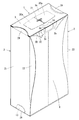
この揺動開閉箱は、図1及び図2に示すように、一側面が開口した本体1と、その開口に嵌められた引出体2とから成り、引出体2の底部一側を支点として本体1に連結し、本体1に対し引出体2を弧状軌跡を描くように揺動させて出し入れするものである。引出体2には、ワイン等の洋酒のボトルが収納される。
As shown in FIGS. 1 and 2, the swing opening / closing box is composed of a
本体1及び引出体2は、図3に示すような板紙のブランクから形成される。本体1のブランクでは、天板3の両端に縦長の外枠板4が連設され、一方の外枠板4に外底板5及び継代片6が順次連設されている。天板3の一側は弧状に切り欠かれ、外枠板4の一側縁は波状とされている。天板3及び外底板5の他側には折曲片7,8が、各外枠板4の他側には背重板9及び外背板10がそれぞれ連設されている。外背板10の先端縁には差込片11が、背重板9の基部にはスリット状の差込穴12がそれぞれ設けられている。
The
外底板5の一側部には、2本の切込間を延長してヒンジ片13が設けられ、その中間部には、幅方向に折目14が入れられている。また、折曲片7の基部にはスリット状の差込穴15が設けられている。
A
一方、引出体2のブランクでは、側出板21の両側に内枠板22が連設され、一方の内枠板22に内背板23及び継代片24が順次連設されている。内枠板22の上端縁には弧状部が形成され、内枠板22の下端には折曲片25が連設されている。側出板21の下端には内底板26及び差込片27が順次連設され、内底板26の基部にはスリット状の差込穴28が設けられている。側出板21の上端には折曲片29が連設されている。
On the other hand, in the blank of the
内背板23の上部には、2本の切込間を延長して連結帯30が設けられ、連結帯30には、先端側に折目31が、中間及び基端に3本の折目32が幅方向に入れられている。連結帯30の折目31よりも先端側は、差込部30aとされている。
An upper part of the
上記ブランクから揺動開閉箱を組み立てるには、図4に示すように、本体1のブランクにおいて、天板3、外枠板4及び外底板5を縦巻きに折り曲げて、継代片6を反対側の外枠板4に貼り付ける。
In order to assemble the swing opening / closing box from the above blank, as shown in FIG. Affixed to the
また、引出体2のブランクにおいて、側出板21、内枠板22及び内背板23を横巻きに折り曲げて、継代片24を反対側の内枠板22に貼り付け、折曲片25を内側へ折り曲げて、内底板26を閉じ、差込片27を折曲片25と内背板23の間に差し込んで、引出体2の底面を閉じる。
Further, in the blank of the
次に、図2及び図5に示すように、本体1に引出体2を嵌め込み、ヒンジ片13を折目14沿いに折り曲げて、その先端部を差込穴28に差し込むと共に、折曲片7,8を下方及び上方へそれぞれ折り曲げ、連結帯30を折目31,32沿いに折り曲げつつ、差込部30aを差込穴15に差し込んで下方へ折り曲げ、背重板9及び外背板10を順次重ね、差込片11を差込穴12に差し込んで、本体1の背面を閉じる。
Next, as shown in FIG. 2 and FIG. 5, the
そして、ボトルの箱詰め時には、図2に示すように、引出体2をヒンジ片13の折目14を支点として本体1から引き出した状態で、ボトルを引出体2に天面の開口を介して収納し、図1に示すように、折曲片29を内側へ折り曲げて、本体1に引出体2を挿入することにより、引出体2の天面の開口を閉止する。
When the bottle is packed, as shown in FIG. 2, the
一方、この揺動開閉箱からボトルを取り出す際には、図2に示すように、本体1から引出体2を露出部分に指を掛けて引き出し、引出体2の天面を開口させて、ボトルを持ち上げる。このとき、連結帯30の折目32に沿った折り曲げが伸びて、連結帯30がストッパとなり、引出体2の抜け出しが防止される。
On the other hand, when taking out the bottle from the swing opening / closing box, as shown in FIG. 2, the
上記のような揺動開閉箱では、本体1と引出体2とが連結帯30を介して連結され、折目32に沿って屈伸する連結帯30により引出体2の開度が規制されるので、本体1に対する引出体2の出し入れをスムーズに行うことができる。
In the swing opening / closing box as described above, the
また、引出体2の開度は、連結帯30の長さを変えることにより調整でき、箱の高さや紙厚に応じて、折目32の位置と本数を適宜設定することにより、開閉時の連結帯30の反発による抵抗を抑制することができる。
Moreover, the opening degree of the
次に、この発明の第2実施形態を図6乃至図9に基づいて説明する。なお、ここでは、上記第1実施形態との相違点について言及し、共通点については説明を省略する。 Next, a second embodiment of the present invention will be described with reference to FIGS. Here, differences from the first embodiment will be referred to, and description of common points will be omitted.
この揺動開閉箱は、図6及び図7に示すように、本体1の両側面が開口し、各開口にそれぞれ引出体2が揺動可能に嵌められている。
As shown in FIGS. 6 and 7, this swinging open / close box has both side surfaces of the
本体1及び引出体2は、図8に示すような板紙のブランクから形成される。本体1のブランクでは、一方の内枠板4に、天板3の下方に重なる内天板3aが連設され、この内天板3aにやや幅が広いスリット状の差込穴15が設けられている。
The
また、天板3の先端には差込片3bが、内天板3aの基端にはスリット状の差込穴3cがそれぞれ設けられ、一方の外枠板4の上部には内天板3aへ至る切込により差込片3dが、差込片3bの基端にはスリット状の差込穴3eがそれぞれ設けられている。
An
一方、引出体2のブランクでは、連結帯30の折目31よりも先端側に長めの差込部30aが設けられ、折目31の一側には、抜止用の切込31aが入れられている。
On the other hand, in the blank of the
そして、組み立てに際しては、図9に示すように、連結帯30の差込部30aを内天板3aの差込穴15に差し込んで外側へ折り返し、図6及び図7に示すように、その上方に天板3を被せ、差込片3bを差込穴3cに差し込んだ後、差込片3dを折り曲げつつ差込穴3eに差し込んで、本体1の天面を閉じる。
When assembling, as shown in FIG. 9, the
上記のような揺動開閉箱では、2本のボトルを各引出体2にそれぞれ収納して、コンパクトに包装でき、連結帯30の屈伸に伴い、本体1に対し2個の引出体2をスムーズに出し入れして、開閉することができる。
In the swing opening and closing box as described above, two bottles can be accommodated in each
なお、上記第2実施形態では、2個の引出体2を横に並べたものを例示したが、長尺の本体1の中間部に仕切を設け、2個の引出体2を、開口した端面同士が仕切を介し対向するように縦に並べて、本体1に収納するようにしてもよい。
In the second embodiment, the two
さらに、1個の引出体2について1本の連結帯30を設けて、本体1と引出体2とを連結しているが、1個の引出体2について複数本の連結帯30を設けて、本体1と引出体2とを連結するようにしてもよい。
Further, one connecting
1 本体
2 引出体
3 天板
3a 内天板
3b 差込片
3c 差込穴
3d 差込片
3e 差込穴
4 外枠板
5 外底板
6 継代片
7,8 折曲片
9 背重板
10 外背板
11 差込片
12 差込穴
13 ヒンジ片
14 折目
15 差込穴
21 側出板
22 内枠板
23 内背板
24 継代片
25 折曲片
26 内底板
27 差込片
28 差込穴
29 折曲片
30 連結帯
30a 差込部
31 折目
31a 切込
32 折目
DESCRIPTION OF
Claims (1)
前記外底板(5)の側部に、2本の切込間を延長してヒンジ片(13)を設け、その中間部に折目(14)を幅方向に入れ、内背板(23)の上部に、2本の切込間を延長して連結帯(30)を設け、その先端側と中間及び基端とに折目(31,32)をそれぞれ幅方向に入れて、連結帯(30)の折目(31)より先端側を差込部(30a)とし、前記本体(1)に引出体(2)を嵌め込み、ヒンジ片(13)を折目(14)に沿って折り曲げ、その先端部を引出体(2)の差込穴(28)に差し込むことにより、引出体(2)の一端部を、ヒンジ片(13)の折目(14)が支点となるように本体(1)に連結し、連結帯(30)を折目(31,32)に沿って折り曲げつつ、差込部(30a)を本体(1)の差込穴(15)に差し込むことにより、引出体(2)の他端部を、連結帯(30)を介して本体(1)に連結し、引出体(2)を本体(1)に収納すると、連結帯(30)が中間及び基端の折目(32)に沿って折れ曲がり、引出体(2)を本体(1)から引き出すと、連結帯(30)が伸びてストッパとなり、引出体(2)の抜け出しが防止されるようにしたことを特徴とする揺動開閉箱。 A top plate (3), a main body (1) in which a pair of outer frame plates (4) and an outer bottom plate (5) are connected , a side plate (21), a pair of inner frame plates (22) and an inner back plate ( made from a 23) bottomed rectangular tubular drawer body which is continuously provided (2), the rotationally opened box and out drawer body (2) is swung relative to the body (1),
On the side of the outer bottom plate (5), a hinge piece (13) is provided by extending between the two cuts, and a fold (14) is inserted in the width direction in the middle of the inner back plate (23). In the upper part of this, a connection band (30) is provided by extending between the two cuts, and folds (31, 32) are inserted in the width direction at the distal end side, the middle and the base end, respectively. The front end side of the fold (31) of (30) is the insertion part (30a), the drawer body (2) is fitted into the main body (1), and the hinge piece (13) is bent along the fold (14), By inserting its tip into the insertion hole (28) of the drawer (2), the main body (1) of the drawer (2) is placed so that the fold (14) of the hinge piece (13) serves as a fulcrum. coupled to 1), while folding along connecting band (30) to the folds (31, 32), by inserting the insertion portion (30a) to the insertion hole (15) of the body (1), out argument When the other end of the body (2) is connected to the main body (1) via the connecting band (30) and the drawer body (2) is stored in the main body (1), the connecting band (30) is connected to the intermediate and proximal ends. Along the crease (32) When the drawer body (2) is pulled out from the main body (1), the connecting band (30) extends to serve as a stopper, preventing the drawer body (2) from coming out. Open / close box.
Priority Applications (1)
| Application Number | Priority Date | Filing Date | Title |
|---|---|---|---|
| JP2006354552A JP4938441B2 (en) | 2006-12-28 | 2006-12-28 | Swing box |
Applications Claiming Priority (1)
| Application Number | Priority Date | Filing Date | Title |
|---|---|---|---|
| JP2006354552A JP4938441B2 (en) | 2006-12-28 | 2006-12-28 | Swing box |
Publications (2)
| Publication Number | Publication Date |
|---|---|
| JP2008162649A JP2008162649A (en) | 2008-07-17 |
| JP4938441B2 true JP4938441B2 (en) | 2012-05-23 |
Family
ID=39692655
Family Applications (1)
| Application Number | Title | Priority Date | Filing Date |
|---|---|---|---|
| JP2006354552A Expired - Fee Related JP4938441B2 (en) | 2006-12-28 | 2006-12-28 | Swing box |
Country Status (1)
| Country | Link |
|---|---|
| JP (1) | JP4938441B2 (en) |
Families Citing this family (4)
| Publication number | Priority date | Publication date | Assignee | Title |
|---|---|---|---|---|
| MX359156B (en) * | 2012-05-02 | 2018-09-17 | Jt Int Sa Star | Packaging having a movable inner packet part. |
| WO2014132408A1 (en) * | 2013-02-28 | 2014-09-04 | 日本たばこ産業株式会社 | Package |
| ITBO20130647A1 (en) * | 2013-11-26 | 2015-05-27 | Gd Spa | PACKAGE OF CONSUMER PRODUCTS. |
| US10131490B2 (en) * | 2014-01-15 | 2018-11-20 | G.D Societa' Per Azioni | Rigid, swing-open package of tobacco articles |
Family Cites Families (3)
| Publication number | Priority date | Publication date | Assignee | Title |
|---|---|---|---|---|
| JPS4824760B1 (en) * | 1969-11-06 | 1973-07-24 | ||
| JPS5657660A (en) * | 1979-10-02 | 1981-05-20 | Gero Gaburieru | Box for distributing tobacco |
| CA2104178C (en) * | 1992-09-01 | 2006-02-14 | Larry Douglas Cobler | Cigarette package assembly |
-
2006
- 2006-12-28 JP JP2006354552A patent/JP4938441B2/en not_active Expired - Fee Related
Also Published As
| Publication number | Publication date |
|---|---|
| JP2008162649A (en) | 2008-07-17 |
Similar Documents
| Publication | Publication Date | Title |
|---|---|---|
| JP4865797B2 (en) | Rigid package for sliding tobacco products | |
| JP4750129B2 (en) | Side open hinge lid container with audible indication of closure and / or opening | |
| JP5739541B2 (en) | Cigarette box | |
| JP6711834B2 (en) | Shoulder pack with lid lifting part | |
| RU2008121276A (en) | PACKAGING FOR SMALL GROUPS OF TOBACCO PRODUCTS | |
| WO2008054305A1 (en) | A package assembly and a blank for forming an insert | |
| JP4938441B2 (en) | Swing box | |
| US9687026B2 (en) | Slide push pack for smoking articles | |
| US8567607B2 (en) | Folding box with a blister pack contained therein | |
| JP5464881B2 (en) | Household thin paper storage container | |
| JP6189925B2 (en) | Swing open hard package for tobacco products | |
| AU2015254990B2 (en) | Carton, carton blank and method of erecting and filling a carton | |
| JP6748722B2 (en) | Nonwoven fabric sanitary cloth sheet storage container | |
| JP5165509B2 (en) | Packaging case with mechanism | |
| UA77659C2 (en) | Pack for smoking articles and plank part for its manufacture | |
| JP5713420B2 (en) | Up-slide package and its blank set | |
| JP4933889B2 (en) | Slide box | |
| JP3166944U (en) | Lead rule for folding cardboard sheets | |
| JP3236551U (en) | Seat storage container | |
| JP7397753B2 (en) | packaging box | |
| JP3229439U (en) | Paper assembly container | |
| JP4429134B2 (en) | Portable paper box | |
| JP4439078B2 (en) | Packaging box | |
| RU2488530C2 (en) | Package | |
| JP5930283B2 (en) | Swing cartons |
Legal Events
| Date | Code | Title | Description |
|---|---|---|---|
| A621 | Written request for application examination |
Free format text: JAPANESE INTERMEDIATE CODE: A621 Effective date: 20090909 |
|
| A977 | Report on retrieval |
Free format text: JAPANESE INTERMEDIATE CODE: A971007 Effective date: 20110825 |
|
| A131 | Notification of reasons for refusal |
Free format text: JAPANESE INTERMEDIATE CODE: A131 Effective date: 20110830 |
|
| A521 | Written amendment |
Free format text: JAPANESE INTERMEDIATE CODE: A523 Effective date: 20110913 |
|
| TRDD | Decision of grant or rejection written | ||
| A01 | Written decision to grant a patent or to grant a registration (utility model) |
Free format text: JAPANESE INTERMEDIATE CODE: A01 Effective date: 20120207 |
|
| A01 | Written decision to grant a patent or to grant a registration (utility model) |
Free format text: JAPANESE INTERMEDIATE CODE: A01 |
|
| A61 | First payment of annual fees (during grant procedure) |
Free format text: JAPANESE INTERMEDIATE CODE: A61 Effective date: 20120223 |
|
| FPAY | Renewal fee payment (event date is renewal date of database) |
Free format text: PAYMENT UNTIL: 20150302 Year of fee payment: 3 |
|
| R150 | Certificate of patent or registration of utility model |
Free format text: JAPANESE INTERMEDIATE CODE: R150 |
|
| R250 | Receipt of annual fees |
Free format text: JAPANESE INTERMEDIATE CODE: R250 |
|
| R250 | Receipt of annual fees |
Free format text: JAPANESE INTERMEDIATE CODE: R250 |
|
| R250 | Receipt of annual fees |
Free format text: JAPANESE INTERMEDIATE CODE: R250 |
|
| LAPS | Cancellation because of no payment of annual fees |