JP4938078B2 - Optical information recording medium reproduction method - Google Patents
Optical information recording medium reproduction method Download PDFInfo
- Publication number
- JP4938078B2 JP4938078B2 JP2009517848A JP2009517848A JP4938078B2 JP 4938078 B2 JP4938078 B2 JP 4938078B2 JP 2009517848 A JP2009517848 A JP 2009517848A JP 2009517848 A JP2009517848 A JP 2009517848A JP 4938078 B2 JP4938078 B2 JP 4938078B2
- Authority
- JP
- Japan
- Prior art keywords
- information recording
- optical information
- recording medium
- reproduction
- film
- Prior art date
- Legal status (The legal status is an assumption and is not a legal conclusion. Google has not performed a legal analysis and makes no representation as to the accuracy of the status listed.)
- Expired - Fee Related
Links
Images


Classifications
-
- G—PHYSICS
- G11—INFORMATION STORAGE
- G11B—INFORMATION STORAGE BASED ON RELATIVE MOVEMENT BETWEEN RECORD CARRIER AND TRANSDUCER
- G11B20/00—Signal processing not specific to the method of recording or reproducing; Circuits therefor
- G11B20/10—Digital recording or reproducing
- G11B20/18—Error detection or correction; Testing, e.g. of drop-outs
-
- G—PHYSICS
- G11—INFORMATION STORAGE
- G11B—INFORMATION STORAGE BASED ON RELATIVE MOVEMENT BETWEEN RECORD CARRIER AND TRANSDUCER
- G11B7/00—Recording or reproducing by optical means, e.g. recording using a thermal beam of optical radiation by modifying optical properties or the physical structure, reproducing using an optical beam at lower power by sensing optical properties; Record carriers therefor
- G11B7/007—Arrangement of the information on the record carrier, e.g. form of tracks, actual track shape, e.g. wobbled, or cross-section, e.g. v-shaped; Sequential information structures, e.g. sectoring or header formats within a track
- G11B7/00736—Auxiliary data, e.g. lead-in, lead-out, Power Calibration Area [PCA], Burst Cutting Area [BCA], control information
-
- G—PHYSICS
- G11—INFORMATION STORAGE
- G11B—INFORMATION STORAGE BASED ON RELATIVE MOVEMENT BETWEEN RECORD CARRIER AND TRANSDUCER
- G11B20/00—Signal processing not specific to the method of recording or reproducing; Circuits therefor
- G11B20/10—Digital recording or reproducing
- G11B20/10009—Improvement or modification of read or write signals
- G11B20/10046—Improvement or modification of read or write signals filtering or equalising, e.g. setting the tap weights of an FIR filter
- G11B20/10055—Improvement or modification of read or write signals filtering or equalising, e.g. setting the tap weights of an FIR filter using partial response filtering when writing the signal to the medium or reading it therefrom
- G11B20/1012—Improvement or modification of read or write signals filtering or equalising, e.g. setting the tap weights of an FIR filter using partial response filtering when writing the signal to the medium or reading it therefrom partial response PR(1,2,2,2,1)
-
- G—PHYSICS
- G11—INFORMATION STORAGE
- G11B—INFORMATION STORAGE BASED ON RELATIVE MOVEMENT BETWEEN RECORD CARRIER AND TRANSDUCER
- G11B20/00—Signal processing not specific to the method of recording or reproducing; Circuits therefor
- G11B20/10—Digital recording or reproducing
- G11B20/10009—Improvement or modification of read or write signals
- G11B20/10481—Improvement or modification of read or write signals optimisation methods
-
- G—PHYSICS
- G11—INFORMATION STORAGE
- G11B—INFORMATION STORAGE BASED ON RELATIVE MOVEMENT BETWEEN RECORD CARRIER AND TRANSDUCER
- G11B7/00—Recording or reproducing by optical means, e.g. recording using a thermal beam of optical radiation by modifying optical properties or the physical structure, reproducing using an optical beam at lower power by sensing optical properties; Record carriers therefor
- G11B7/24—Record carriers characterised by shape, structure or physical properties, or by the selection of the material
- G11B7/2403—Layers; Shape, structure or physical properties thereof
- G11B7/24065—Layers assisting in recording or reproduction below the optical diffraction limit, e.g. non-linear optical layers or structures
-
- G—PHYSICS
- G11—INFORMATION STORAGE
- G11B—INFORMATION STORAGE BASED ON RELATIVE MOVEMENT BETWEEN RECORD CARRIER AND TRANSDUCER
- G11B20/00—Signal processing not specific to the method of recording or reproducing; Circuits therefor
- G11B20/10—Digital recording or reproducing
- G11B20/12—Formatting, e.g. arrangement of data block or words on the record carriers
- G11B20/1217—Formatting, e.g. arrangement of data block or words on the record carriers on discs
-
- G—PHYSICS
- G11—INFORMATION STORAGE
- G11B—INFORMATION STORAGE BASED ON RELATIVE MOVEMENT BETWEEN RECORD CARRIER AND TRANSDUCER
- G11B20/00—Signal processing not specific to the method of recording or reproducing; Circuits therefor
- G11B20/10—Digital recording or reproducing
- G11B20/14—Digital recording or reproducing using self-clocking codes
- G11B20/1403—Digital recording or reproducing using self-clocking codes characterised by the use of two levels
- G11B20/1423—Code representation depending on subsequent bits, e.g. delay modulation, double density code, Miller code
- G11B20/1426—Code representation depending on subsequent bits, e.g. delay modulation, double density code, Miller code conversion to or from block codes or representations thereof
-
- G—PHYSICS
- G11—INFORMATION STORAGE
- G11B—INFORMATION STORAGE BASED ON RELATIVE MOVEMENT BETWEEN RECORD CARRIER AND TRANSDUCER
- G11B2220/00—Record carriers by type
- G11B2220/20—Disc-shaped record carriers
- G11B2220/25—Disc-shaped record carriers characterised in that the disc is based on a specific recording technology
- G11B2220/2537—Optical discs
- G11B2220/2541—Blu-ray discs; Blue laser DVR discs
-
- G—PHYSICS
- G11—INFORMATION STORAGE
- G11B—INFORMATION STORAGE BASED ON RELATIVE MOVEMENT BETWEEN RECORD CARRIER AND TRANSDUCER
- G11B2220/00—Record carriers by type
- G11B2220/20—Disc-shaped record carriers
- G11B2220/25—Disc-shaped record carriers characterised in that the disc is based on a specific recording technology
- G11B2220/2537—Optical discs
- G11B2220/2579—HD-DVDs [high definition DVDs]; AODs [advanced optical discs]
-
- G—PHYSICS
- G11—INFORMATION STORAGE
- G11B—INFORMATION STORAGE BASED ON RELATIVE MOVEMENT BETWEEN RECORD CARRIER AND TRANSDUCER
- G11B7/00—Recording or reproducing by optical means, e.g. recording using a thermal beam of optical radiation by modifying optical properties or the physical structure, reproducing using an optical beam at lower power by sensing optical properties; Record carriers therefor
- G11B7/24—Record carriers characterised by shape, structure or physical properties, or by the selection of the material
- G11B7/241—Record carriers characterised by shape, structure or physical properties, or by the selection of the material characterised by the selection of the material
- G11B7/252—Record carriers characterised by shape, structure or physical properties, or by the selection of the material characterised by the selection of the material of layers other than recording layers
- G11B7/258—Record carriers characterised by shape, structure or physical properties, or by the selection of the material characterised by the selection of the material of layers other than recording layers of reflective layers
Abstract
Description
本発明は、情報の光学的な記録再生が可能な光情報記録媒体、および該光情報記録媒体に記録された情報を再生する光情報処理装置に関するものである。 The present invention relates to an optical information recording medium capable of optically recording and reproducing information, and an optical information processing apparatus for reproducing information recorded on the optical information recording medium.
従来から、情報通信技術およびマルチメディア技術の発展、ならびに高度情報化によって、光情報記録媒体の高密度化、大容量化の要求が高まってきている。しかしながら、光情報記録媒体の記録密度の上限は、主に情報を記録または再生する光ビームのスポット径によって制限されている。これは、光情報記録媒体の記録マーク径を縮小して高密度化するにつれて、スポット領域内に複数のマークが含まれるようになり、各マークを個別に検知することができなくなるためである。なお、光源の波長をλ、光スポットを形成するための対物レンズの開口数をNAとすると、光ビームのスポット径は、ほぼλ/NAで表されることになる。従って、光源の波長λを短くするとともに、対物レンズの開口数NAを増加させることにより、光ビームのスポット径を縮小しさえすれば、光情報記録媒体の記録密度の向上が可能であるとされてきた。 2. Description of the Related Art Conventionally, with the development of information communication technology and multimedia technology and advanced information technology, demands for higher density and larger capacity of optical information recording media have been increasing. However, the upper limit of the recording density of the optical information recording medium is limited mainly by the spot diameter of the light beam for recording or reproducing information. This is because as the recording mark diameter of the optical information recording medium is reduced and the recording density is increased, a plurality of marks are included in the spot region, and each mark cannot be detected individually. When the wavelength of the light source is λ and the numerical aperture of the objective lens for forming the light spot is NA, the spot diameter of the light beam is approximately expressed by λ / NA. Therefore, it is said that the recording density of the optical information recording medium can be improved by reducing the spot diameter of the light beam by shortening the wavelength λ of the light source and increasing the numerical aperture NA of the objective lens. I came.
しかしながら、光情報記録媒体の再生装置の、光学素子の吸収の問題および検出器の感度特性の制限の問題により、紫外線領域の波長が光源の波長λの限界と考えられること、および光情報記録媒体の再生装置の対物レンズの開口数NAの向上が、光情報記録媒体の傾きの許容量によってほぼ制限されることなどから、光ビームのスポット径を縮小することによって光情報記録媒体の記録密度の向上を図るには限界がある。 However, the wavelength of the ultraviolet region is considered to be the limit of the wavelength λ of the light source due to the problem of absorption of the optical element and the limitation of the sensitivity characteristic of the detector of the reproducing apparatus of the optical information recording medium, and the optical information recording medium Since the improvement of the numerical aperture NA of the objective lens of the reproducing apparatus is almost limited by the allowable amount of tilt of the optical information recording medium, the recording density of the optical information recording medium can be reduced by reducing the spot diameter of the light beam. There is a limit to improvement.
そこで、近年では、再生光学系(光情報記録媒体の再生装置の光学系)の解像限界(再生光の回折限界で決まる光学的分解能)以下のマーク長を再生可能な技術である超解像再生技術を用いた光情報記録媒体の開発がなされてきた。なお、上述のような超解像再生技術を用いることによって、再生光学系の解像限界以下のマーク長が再生可能になるので、より小さなマーク長を使用した光情報記録媒体への記録が可能となる。つまり、上述のような超解像再生技術を用いることによって、実質的な光情報記録媒体の記録密度を増加させることが可能になる。以降では、前記技術を用いた光情報記録媒体を超解像再生媒体と呼ぶとともに、前記技術を用いて再生光学系の解像限界以下のマーク長の記録ピットを再生することを超解像再生と呼ぶ。 Therefore, in recent years, super-resolution, a technology that can reproduce mark lengths below the resolution limit (optical resolution determined by the diffraction limit of the reproduction light) of the reproduction optical system (optical system of the reproduction apparatus for optical information recording media). Optical information recording media using reproduction technology have been developed. In addition, since the mark length below the resolution limit of the reproduction optical system can be reproduced by using the super-resolution reproduction technique as described above, recording on an optical information recording medium using a smaller mark length is possible. It becomes. That is, the recording density of the optical information recording medium can be substantially increased by using the super-resolution reproduction technique as described above. Hereinafter, the optical information recording medium using the above technique is referred to as a super-resolution reproduction medium, and the reproduction of a recording pit having a mark length less than the resolution limit of the reproduction optical system using the technique is super-resolution reproduction. Call it.
なお、再生光学系の解像限界は、検出可能な信号の周波数限界の制約を受け、一般的には、λ/(2NA)程度になると言われている(λ:再生光波長、NA:レンズの開口率)が、上述のλ/(2NA)程度とは、単一サイズの記録マークとスペースとの繰り返しからなるパターンの周期サイズの解像限界に相当し、その半分のλ/(4NA)程度が、記録マークの長さの解像限界となることが知られている。よって、以降では、記録マークの長さの解像限界を解像限界とし、解像限界をλ/(4NA)とする。なお、実際には、理論以外にも光学系内の他要素の影響を受けるので、解像限界の値は波長および開口数から求められる理論値からある程度の差を生じる場合がある。 Note that the resolution limit of the reproduction optical system is limited by the frequency limit of the detectable signal, and is generally said to be about λ / (2NA) (λ: reproduction light wavelength, NA: lens). The aperture ratio is about the above-mentioned λ / (2NA), which corresponds to the resolution limit of the periodic size of a pattern formed by repeating a single-size recording mark and a space, and half of that is λ / (4NA). It is known that the degree becomes the resolution limit of the length of the recording mark. Therefore, hereinafter, the resolution limit of the length of the recording mark is set as the resolution limit, and the resolution limit is set to λ / (4NA). Actually, since it is affected by other elements in the optical system besides the theory, the value of the resolution limit may cause a certain difference from the theoretical value obtained from the wavelength and the numerical aperture.
上述した解像限界を超えた「超解像再生」を可能とする技術として、例えば、特許文献1では、詳細な再生原理は不明であるが、凹凸を有する情報記録面に金属、半導体等の単体、合金、または化合物からなる、空間分解能を向上させる機能層を備えることにより、超解像再生を可能とする光情報記録媒体が開示されている。特許文献1に開示の光情報記録媒体では、解像限界以下の同一形状のマークを、信号再生する方向に配置する方式が採用されている。具体的には、単一周波数繰り返し位相ピット(マーク・スペース比1:1)を再生し、CNR(carrier-to-noise ratio、搬送波対雑音比)を用いて前記方式の評価を行ったところ、前記方式によって記録密度が向上し、超解像再生が可能になったことが述べられている。なお、上述したようなピットパターンを、以降ではモノトーンパターンと呼ぶものとする。 As a technology that enables “super-resolution reproduction” exceeding the above-described resolution limit, for example, in Patent Document 1, although the detailed reproduction principle is unknown, a metal, semiconductor, or the like is formed on an information recording surface having irregularities. An optical information recording medium that is capable of super-resolution reproduction by providing a functional layer made of a simple substance, an alloy, or a compound that improves spatial resolution is disclosed. The optical information recording medium disclosed in Patent Document 1 employs a system in which marks having the same shape below the resolution limit are arranged in the signal reproduction direction. Specifically, a single frequency repetitive phase pit (mark / space ratio of 1: 1) was reproduced, and the above-described method was evaluated using CNR (carrier-to-noise ratio). It is stated that the recording density is improved by the above-mentioned method and super-resolution reproduction is possible. The pit pattern as described above is hereinafter referred to as a monotone pattern.
一方、信号処理の観点からの光情報記録媒体の高密度化手段として、一般的には、マークエッジ記録方式が採用されている。マークエッジ記録方式は、1つの記録マークの両端を信号として使用することによって光情報記録媒体の高密度化を可能にする方式であって、再生ビーム走査方向に対して最も短いマーク長となる最小長さのプリピットと、前記最小長さを基準にした数種類の長さのプリピットとが規格によって定められているとともに、長さの異なる前記プリピットが、規格によって定められた規則に従って、信号再生する方向に順に配置されるものである。なお、上述したようなピットパターンを、以降ではランダムパターンと呼ぶものとする。 On the other hand, as a means for increasing the density of an optical information recording medium from the viewpoint of signal processing, a mark edge recording method is generally employed. The mark edge recording method is a method that enables high-density recording of an optical information recording medium by using both ends of one recording mark as a signal, and is the minimum mark length that is the shortest in the reproduction beam scanning direction. The prepits of length and several types of prepits based on the minimum length are defined by the standard, and the prepits having different lengths are in the direction of signal reproduction according to the rules defined by the standard. Are arranged in order. The pit pattern as described above is hereinafter referred to as a random pattern.
また、ランダムパターンを用いたマークエッジ記録方式には、数多くの実用化例があり、例えば、CD(Compact Disc)の場合は、変調方式としてEFM(8/14)(Eight to Fourteen Modulation)を採用している。他にも、DVD(Digital Versatile Disk)、BD(Blu-ray Disc)、HD DVD(High-Definition Digital Versatile Disk)では、変調方式がそれぞれCDとは異なっており、DVDではEFMPlus(8/16)、BDではRLL(1,7)、HD DVDではETM(8/12)(Eight to Twelve Modulation)がそれぞれ採用されている。 Also, there are many practical examples of mark edge recording methods using random patterns. For example, in the case of CD (Compact Disc), EFM (8/14) (Eight to Fourteen Modulation) is adopted as a modulation method. is doing. In addition, DVD (Digital Versatile Disk), BD (Blu-ray Disc), and HD DVD (High-Definition Digital Versatile Disk) have different modulation schemes from CD, and DVD uses EFMPplus (8/16). BD employs RLL (1, 7), and HD DVD employs ETM (8/12) (Eight to Twelve Modulation).
すなわち、多くの光情報記録媒体には、ランダムパターンを用いたマークエッジ記録方式が採用されている。これは、モノトーンパターンを用いて記録を行う場合と比べて、ランダムパターンからなるマークエッジ記録方式を用いて記録を行う方が、より高密度に情報が記録できるためである。従って、実用化のためには、ランダムパターンを用いた光情報記録媒体の評価が必要となる。なお、前記評価の指標としては、例えばbER(Bit Error Rate)が挙げられる。bERは、ビット誤り率とも言い、光情報記録媒体に記録されたランダムパターンを再生した信号を復号した結果に含まれるエラービット数Neの、全復号ビット数Ntに対する比率であって、bER=Ne/Ntである。 That is, many optical information recording media employ a mark edge recording method using a random pattern. This is because information can be recorded at a higher density when recording is performed using a mark edge recording method including a random pattern than when recording is performed using a monotone pattern. Therefore, for practical use, it is necessary to evaluate an optical information recording medium using a random pattern. An example of the evaluation index is bER (Bit Error Rate). bER is also referred to as a bit error rate, and is a ratio of the number of error bits Ne included in a result of decoding a signal reproduced from a random pattern recorded on an optical information recording medium to the total number of decoded bits Nt, and bER = Ne / Nt.
また、ランダムパターンを用いたマークエッジ記録方式により高密度記録された光情報記録媒体の再生においては、PRML(Partial Response Maximum Likelihood)復号が用いられる。従来の光情報記録媒体においては、信号検出法としてピーク・ディテクトが一般的であったが、近年のBDおよびHD DVDのような高密度光情報記録媒体においては、PRML復号が事実上必須であり、一般的に用いられている。 In addition, PRML (Partial Response Maximum Likelihood) decoding is used in reproducing an optical information recording medium recorded at high density by a mark edge recording method using a random pattern. In conventional optical information recording media, peak detection is generally used as a signal detection method. However, in recent high-density optical information recording media such as BD and HD DVD, PRML decoding is practically essential. Is commonly used.
なお、PRMLの例としては、HD DVDで用いられるPR(12221)MLなどが挙げられる。また、例えば、非特許文献1では、ランダムパターンの超解像再生のbER特性を改善するための、Super−RENSと呼ばれる超解像再生方式の信号復号方式について開示されている。具体的には、非特許文献1では、ランダムパターンの超解像再生のbER特性を改善するために、PRML信号復号方式を発展させた信号処理について開示されている。
しかしながら、特許文献1に開示の光情報記録媒体では、ランダムパターンを用いて記録を行った場合の再生信号品質の評価は行われていない。後に詳述するが、特許文献1に開示の光情報記録媒体に解像限界以下のマーク長を含んだランダムパターンで情報が記録された場合には、一般的に使われるPRML復号方式を用いて、良好なbER値が得られる信号再生を行うことができないという問題点が生じる。 However, the optical information recording medium disclosed in Patent Document 1 does not evaluate the reproduction signal quality when recording is performed using a random pattern. As will be described in detail later, when information is recorded on the optical information recording medium disclosed in Patent Document 1 with a random pattern including a mark length less than the resolution limit, a commonly used PRML decoding method is used. Therefore, there arises a problem that it is impossible to perform signal reproduction with which a good bER value can be obtained.
ランダムパターンの超解像再生時に信号誤りが大きくなることは、非特許文献2にも記載されているように、従来の超解像再生特有の本質的な課題であることがよく知られている。なお、非特許文献2には、ランダムパターンの超解像再生時の信号誤り率を低下させるための技術について開示されているが、前記技術は、低周波信号のみを取り除く、従来に比べて特殊である新規の雑音処理回路技術を用いているため、汎用性の高い復号方式および再生装置を利用して再生を行うことができないという問題点を有している。すなわち、汎用性に欠けるという問題点を有している。
It is well known that a signal error becomes large at the time of super-resolution reproduction of a random pattern, as described in Non-Patent
また、非特許文献1に開示の信号処理では、明確に記載されてはいないが、コスト高および消費電力増が予想される新規のPRML信号復号方式を用いて再生を行っているので、前記新規のPRML信号復号方式を用いなければ、解像限界以下のマーク長を含んだランダムパターンで記録された情報について、良好なbER値が得られる信号再生を行うことができない。すなわち、一般的に使われているPRML復号方式を用いて、良好なbER値が得られる信号再生を行うことができず、汎用性に欠けるという問題点がある。 Further, in the signal processing disclosed in Non-Patent Document 1, although it is not clearly described, reproduction is performed using a new PRML signal decoding method that is expected to increase cost and increase power consumption. If the PRML signal decoding method is not used, it is impossible to perform signal reproduction for obtaining a good bER value for information recorded in a random pattern including a mark length equal to or less than the resolution limit. That is, there is a problem in that it is not possible to perform signal reproduction with a good bER value using a commonly used PRML decoding method, and lack general versatility.
以上のように、従来までの技術では、より高密度記録となる解像限界以下のマーク長を含んだランダムパターンで記録された情報について、汎用性の高い一般的なPRML復号方式を用いて、良好なbER値が得られる信号再生を行うことができないという問題があった。 As described above, in the conventional technology, for information recorded in a random pattern including a mark length that is less than or equal to the resolution limit for higher density recording, using a general PRML decoding method with high versatility, There has been a problem that it is not possible to perform signal reproduction with which a good bER value can be obtained.
本発明は、前記従来の問題点に鑑みなされたものであって、その目的は、解像限界以下のマーク長を含んだランダムパターンで情報が記録された場合に、汎用性の高い信号復号方式を用いて、より良好なbER値が得られる超解像再生を可能にする光情報記録媒体および光情報処理装置を提供することにある。 The present invention has been made in view of the above-described conventional problems, and its purpose is to provide a highly versatile signal decoding method when information is recorded in a random pattern including a mark length that is less than or equal to the resolution limit. Is used to provide an optical information recording medium and an optical information processing apparatus that enable super-resolution reproduction with a better bER value.
本発明の光情報記録媒体は、前記課題を解決するために、基板上に、情報記録層と、透光層とが積層され、開口数0.84以上かつ0.86以下の対物レンズを介して波長400nm以上かつ410nm以下の再生光で再生される光情報記録媒体であって、前記情報記録層には、RLL(1,7)変調方式によって、記録情報が、複数の長さを有するマークおよびスペースとして形成されるとともに、前記複数の長さを有するマークおよびスペースのうちの、2Tマークならびに2Tスペースの長さが0.12μmよりも短く形成され、さらに、前記情報記録層は、前記再生光による再生信号波形が、PR(12221)ML方式にて復号され、誤り訂正されて再生されることを可能とする、少なくとも1層の薄膜からなることを特徴としている。 In order to solve the above-described problems, the optical information recording medium of the present invention includes an information recording layer and a light-transmitting layer laminated on a substrate, through an objective lens having a numerical aperture of 0.84 or more and 0.86 or less. An optical information recording medium that is reproduced with reproducing light having a wavelength of 400 nm or more and 410 nm or less, and the information recording layer has a mark having a plurality of lengths in accordance with the RLL (1, 7) modulation method. The 2T mark and 2T space of the plurality of marks and spaces having a plurality of lengths are formed to be shorter than 0.12 μm, and the information recording layer further includes the reproducing layer. It is characterized in that it consists of at least one layer of thin film that enables a reproduced signal waveform by light to be decoded and corrected by the PR (12221) ML method. That.
前記の発明によれば、基板上に、情報記録層と、透光層とが積層され、開口数0.84以上かつ0.86以下の対物レンズを介して青紫色波長400nm以上かつ410nm以下の再生光で再生される光情報記録媒体の、再生光の回折限界で決まる光学的分解能以下、すなわち再生光学系の解像限界以下の、0.12μmよりも短く形成される2Tマークならびに2Tスペースを含む、RLL(1,7)変調方式によって高密度に変調されたランダムパターンを、多くの非超解像媒体再生装置にも、すでに搭載されている比較的安価な従来からあるPR(12221)ML方式を用いて、復号再生することが可能となる。 According to the invention, the information recording layer and the light transmitting layer are laminated on the substrate, and the blue-violet wavelength is 400 nm or more and 410 nm or less through the objective lens having a numerical aperture of 0.84 or more and 0.86 or less. A 2T mark and a 2T space formed shorter than 0.12 μm, which are less than the optical resolution determined by the diffraction limit of the reproduction light, that is, less than the resolution limit of the reproduction optical system, of the optical information recording medium reproduced by the reproduction light. A relatively inexpensive conventional PR (12221) ML that is already installed in many non-super-resolution medium playback devices, including random patterns modulated in high density by the RLL (1, 7) modulation method. It is possible to perform decoding and reproduction using the method.
なお、本発明の情報記録層は、誤り訂正されて再生されることを可能とする構成であるので、誤りがあったとしても誤り訂正が可能なだけのbER値が得られる。すなわち、本発明によれば、より良好なbER値が得られる。また、誤り訂正されて再生されることによって、高信頼性を有した実用化も可能となる。 Since the information recording layer of the present invention is configured to be reproduced with error correction, even if there is an error, a bER value sufficient for error correction can be obtained. That is, according to the present invention, a better bER value can be obtained. In addition, since the error is corrected and reproduced, practical use with high reliability becomes possible.
その結果、解像限界以下のマーク長を含んだランダムパターンで情報が記録された場合に、汎用性の高い信号復号方式を用いて、より良好なbER値が得られる超解像再生が可能になる。 As a result, when information is recorded in a random pattern including a mark length that is less than or equal to the resolution limit, super-resolution reproduction that can obtain a better bER value is possible using a highly versatile signal decoding method. Become.
また、多くの非超解像媒体再生装置にも、すでに搭載されているPR(12221)ML方式を用いて、高品質に復号再生を行うことができるので、従来からある非超解像媒体再生装置にて再生レーザーパワーを適切な値にするだけで、超解像再生が可能になる。すなわち、超解像媒体と非超解像媒体とのいずれをも共用再生することが可能になる。 In addition, many non-super-resolution medium playback apparatuses can perform high-quality decoding and playback using the already-installed PR (12221) ML system, so that conventional non-super-resolution medium playback is possible. Super-resolution reproduction is possible only by setting the reproduction laser power to an appropriate value in the apparatus. That is, both the super-resolution medium and the non-super-resolution medium can be shared and reproduced.
また、本発明の光情報記録媒体は、前記課題を解決するために、基板上に、情報記録層が形成されている光情報記録媒体であって、前記情報記録層には、所定の変調方式によって、記録情報が、複数の長さを有するマークおよびスペースとして形成されるとともに、前記複数の長さを有するマークおよびスペースのうちの、最短マークならびに最短スペースが、再生光学系の解像限界以下の長さで形成され、さらに、前記情報記録層は、酸化亜鉛、チタン酸ストロンチウム、酸化チタン、酸化セリウム、または少なくともそれらのうちのいずれかを含む材料からなる再生膜と、タンタルまたはチタンからなる反射膜とを、再生光の入射側から順に有していることを特徴としている。 The optical information recording medium of the present invention is an optical information recording medium in which an information recording layer is formed on a substrate in order to solve the above-mentioned problem, and the information recording layer has a predetermined modulation method. The recorded information is formed as marks and spaces having a plurality of lengths, and the shortest mark and the shortest space among the marks and spaces having the plurality of lengths are below the resolution limit of the reproducing optical system. Furthermore, the information recording layer is made of zinc oxide, strontium titanate, titanium oxide, cerium oxide, or a reproducing film made of a material containing at least one of them, and tantalum or titanium. A reflective film is provided in order from the incident side of the reproduction light.
従来からある超解像技術を利用し作製された再生光の回折限界で決まる光学的分解能(再生光学系の解像限界)以下の長さの記録マークを含む、ランダムパターン方式の光情報記録媒体では、C/Nが向上した場合であっても、bER値が良好な値を満たすとは限らない。このため、bER値を低減させることは、安定した超解像再生を行う上で重要である。 Random pattern type optical information recording medium including recording marks with a length less than or equal to the optical resolution determined by the diffraction limit of reproduction light produced using conventional super-resolution technology (resolution limit of reproduction optical system) Then, even if C / N is improved, the bER value does not always satisfy a good value. For this reason, reducing the bER value is important in performing stable super-resolution reproduction.
本発明者は、基板上に形成される情報記録層が、再生光の入射側から順に、再生膜と反射膜とを有する場合であって、再生膜が酸化亜鉛、チタン酸ストロンチウム、酸化チタン、酸化セリウム、または少なくともそれらのうちのいずれかを含む材料からなるとともに、反射膜がタンタルまたはチタンからなるときに、所定の変調方式によって、複数の長さを有するマークおよびスペースとして形成される記録情報(ランダムパターン)に対して、より良好なbER値が得られる超解像再生が可能になることを、今回初めて見出した(図6および図8参照)。 The inventor is a case where the information recording layer formed on the substrate has a reproduction film and a reflection film in order from the reproduction light incident side, and the reproduction film is zinc oxide, strontium titanate, titanium oxide, Recording information formed as marks and spaces having a plurality of lengths by a predetermined modulation method when the reflective film is made of tantalum or titanium and made of cerium oxide or a material containing at least one of them. It has been found for the first time that super-resolution reproduction with a better bER value is possible for (random pattern) (see FIGS. 6 and 8).
すなわち、前記の発明によれば、解像限界以下のマーク長を含んだランダムパターンで情報が記録された場合に、汎用性の高い信号復号方式を用いて、より良好なbER値が得られる超解像再生が可能になる。 That is, according to the above-described invention, when information is recorded with a random pattern including a mark length less than or equal to the resolution limit, a more versatile signal decoding method can be used to obtain a better bER value. Resolution playback becomes possible.
前記の発明の光情報記録媒体においては、再生時の再生光入射により、情報記録層における再生ビームスポット内の一部領域において、反射膜が前記再生光の一部を吸収して熱に変換することにより、前記再生膜の温度を上昇させる。これにより、前記再生光の波長における再生膜の光学定数(屈折率および/または消衰係数)が変化し、結果として前記領域の光学多重干渉の状態を変化させ、超解像再生が可能になるものと考えられる。 In the optical information recording medium of the above invention, the reflection film absorbs a part of the reproduction light and converts it into heat in a partial region in the reproduction beam spot in the information recording layer by the incidence of the reproduction light during reproduction. As a result, the temperature of the regeneration film is increased. As a result, the optical constant (refractive index and / or extinction coefficient) of the reproducing film at the wavelength of the reproducing light changes, and as a result, the state of optical multiple interference in the region is changed, and super-resolution reproduction becomes possible. It is considered a thing.
また、前記の発明によれば、再生膜と反射膜とをそれぞれ分離形成し、再生膜と反射膜とで光吸収し発熱する機能と光学特性を変化させる機能とを分担しているので、再生膜自体が光吸収し発熱した上で光学特性を変化させて超解像再生を実現する必要がない。よって、再生膜に多くの負担をかけることなく超解像再生を行うことが可能となり、再生膜の耐久性を向上させることができる。また、再生膜と反射膜とで光吸収し発熱する機能と光学特性を変化させる機能とを分担するので、再生膜に対しての機能性要求を少なくすることができ、材料設計の自由度を高くすることも可能になる。 Further, according to the invention, the reproducing film and the reflecting film are separately formed, and the reproducing film and the reflecting film share the function of absorbing light and generating heat and the function of changing the optical characteristics. It is not necessary to realize super-resolution reproduction by changing the optical characteristics after the film itself absorbs light and generates heat. Therefore, it is possible to perform super-resolution reproduction without imposing a lot of burden on the reproduction film, and the durability of the reproduction film can be improved. In addition, since the reproducing film and the reflecting film share the function of absorbing light and generating heat and the function of changing the optical characteristics, it is possible to reduce the functional requirements for the reproducing film and to increase the degree of freedom in material design. It can also be raised.
また、本発明の光情報記録媒体は、前記課題を解決するために、基板上に、情報記録層と、透光層とが積層され、開口数0.84以上かつ0.86以下の対物レンズを介して波長400nm以上かつ410nm以下の再生光で再生される光情報記録媒体であって、前記情報記録層には、RLL(1,7)変調方式によって、記録情報が、複数の長さを有するマークおよびスペースとして形成されるとともに、前記複数の長さを有するマークおよびスペースのうちの、2Tマークならびに2Tスペースの長さが0.12μmより短く形成され、さらに、前記情報記録層は、酸化亜鉛、チタン酸ストロンチウム、酸化チタン、酸化セリウム、または少なくともそれらのうちのいずれかを含む材料からなる再生膜と、タンタルまたはチタンからなる反射膜とを、前記再生光の入射側から順に有していることを特徴としている。 In order to solve the above problems, the optical information recording medium of the present invention includes an information recording layer and a light transmitting layer laminated on a substrate, and an objective lens having a numerical aperture of 0.84 or more and 0.86 or less. The optical information recording medium is reproduced with reproducing light having a wavelength of 400 nm or more and 410 nm or less via the recording information, and the information recording layer has a plurality of lengths of recorded information by an RLL (1, 7) modulation method. The 2T mark and the 2T space among the plurality of marks and spaces having a length of less than 0.12 μm are formed, and the information recording layer is oxidized. Recycled film made of zinc, strontium titanate, titanium oxide, cerium oxide, or a material containing at least one of them, and made of tantalum or titanium A reflection film, is characterized by having in order from the entrance side of the reproduction light.
本発明者は、基板上に形成される情報記録層が、再生光の入射側から順に、再生膜と反射膜とを有する場合であって、再生膜が酸化亜鉛、チタン酸ストロンチウム、酸化チタン、酸化セリウム、または少なくともそれらのうちのいずれかを含む材料からなるとともに、反射膜がタンタルまたはチタンからなるときに、所定の変調方式によって、複数の長さを有するマークおよびスペースとして形成される記録情報(ランダムパターン)に対して、より良好なbER値が得られる超解像再生が可能になることを、今回初めて見出した(図6および図8参照)。 The inventor is a case where the information recording layer formed on the substrate has a reproduction film and a reflection film in order from the reproduction light incident side, and the reproduction film is zinc oxide, strontium titanate, titanium oxide, Recording information formed as marks and spaces having a plurality of lengths by a predetermined modulation method when the reflective film is made of tantalum or titanium and made of cerium oxide or a material containing at least one of them. It has been found for the first time that super-resolution reproduction with a better bER value is possible for (random pattern) (see FIGS. 6 and 8).
すなわち、前記の発明によれば、情報記録層と、透光層とが積層され、開口数0.84以上かつ0.86以下の対物レンズを介して波長400nm以上かつ410nm以下の再生光で再生される光情報記録媒体に、解像限界以下のマーク長を含んだランダムパターン、つまり、RLL(1,7)変調方式によって、2Tマークならびに2Tスペースの長さが0.12μmより短く形成されるパターンで情報が記録された場合に、汎用性の高い信号復号方式を用いて、より良好なbER値が得られる超解像再生が可能になる。 That is, according to the above-described invention, the information recording layer and the light-transmitting layer are laminated, and reproduction is performed with reproduction light having a wavelength of 400 nm or more and 410 nm or less through an objective lens having a numerical aperture of 0.84 or more and 0.86 or less. The 2T mark and 2T space length is shorter than 0.12 μm by a random pattern including a mark length less than the resolution limit, that is, the RLL (1, 7) modulation method. When information is recorded in a pattern, it is possible to perform super-resolution reproduction with a better bER value using a highly versatile signal decoding method.
前記の発明の光情報記録媒体においては、再生時の再生光入射により、情報記録層における再生ビームスポット内の一部領域において、反射膜が前記再生光の一部を吸収して熱に変換することにより、前記再生膜の温度を上昇させる。これにより、前記再生光の波長における再生膜の光学定数(屈折率および/または消衰係数)が変化し、結果として前記領域の光学多重干渉の状態を変化させ、超解像再生が可能になるものと考えられる。 In the optical information recording medium of the above invention, the reflection film absorbs a part of the reproduction light and converts it into heat in a partial region in the reproduction beam spot in the information recording layer by the incidence of the reproduction light during reproduction. As a result, the temperature of the regeneration film is increased. As a result, the optical constant (refractive index and / or extinction coefficient) of the reproducing film at the wavelength of the reproducing light changes, and as a result, the state of optical multiple interference in the region is changed, and super-resolution reproduction becomes possible. It is considered a thing.
また、前記の発明によれば、再生膜と反射膜とをそれぞれ分離形成し、再生膜と反射膜とで光吸収し発熱する機能と光学特性を変化させる機能とを分担しているので、再生膜自体が光吸収し発熱した上で光学特性を変化させて超解像再生を実現する必要がない。よって、再生膜に多くの負担をかけることなく超解像再生を行うことが可能となり、再生膜の耐久性を向上させることができる。また、再生膜と反射膜とで光吸収し発熱する機能と光学特性を変化させる機能とを分担するので、再生膜に対しての機能性要求を少なくすることができ、材料設計の自由度を高くすることも可能になる。 Further, according to the invention, the reproducing film and the reflecting film are separately formed, and the reproducing film and the reflecting film share the function of absorbing light and generating heat and the function of changing the optical characteristics. It is not necessary to realize super-resolution reproduction by changing the optical characteristics after the film itself absorbs light and generates heat. Therefore, it is possible to perform super-resolution reproduction without imposing a lot of burden on the reproduction film, and the durability of the reproduction film can be improved. In addition, since the reproducing film and the reflecting film share the function of absorbing light and generating heat and the function of changing the optical characteristics, it is possible to reduce the functional requirements for the reproducing film and to increase the degree of freedom in material design. It can also be raised.
本発明の光情報記録媒体は、以上のように、前記情報記録層には、RLL(1,7)変調方式によって、記録情報が、複数の長さを有するマークおよびスペースとして形成されるとともに、前記複数の長さを有するマークおよびスペースのうちの、2Tマークならびに2Tスペースの長さが0.12μmよりも短く形成され、さらに、前記情報記録層は、前記再生光による再生信号波形が、PR(12221)ML方式にて復号され、誤り訂正されて再生されることを可能とする、少なくとも1層の薄膜からなるものである。 In the optical information recording medium of the present invention, as described above, in the information recording layer, recorded information is formed as marks and spaces having a plurality of lengths by the RLL (1, 7) modulation method, Of the marks and spaces having the plurality of lengths, the 2T mark and the 2T space are formed to have a length shorter than 0.12 μm. (12221) It is composed of at least one layer of thin film that can be decoded by the ML method, error-corrected and reproduced.
また、本発明の光情報記録媒体は、以上のように、前記情報記録層には、所定の変調方式によって、記録情報が、複数の長さを有するマークおよびスペースとして形成されるとともに、前記複数の長さを有するマークおよびスペースのうちの、最短マークならびに最短スペースが、再生光学系の解像限界以下の長さで形成され、さらに、前記情報記録層は、酸化亜鉛、チタン酸ストロンチウム、酸化チタン、酸化セリウム、または少なくともそれらのうちのいずれかを含む材料からなる再生膜と、タンタルまたはチタンからなる反射膜とを、再生光の入射側から順に有しているものである。 In the optical information recording medium of the present invention, as described above, in the information recording layer, recorded information is formed as marks and spaces having a plurality of lengths by a predetermined modulation method. The shortest mark and the shortest space of the marks and spaces having the lengths of: A reproducing film made of titanium, cerium oxide, or a material containing at least one of them, and a reflective film made of tantalum or titanium are sequentially provided from the incident side of the reproducing light.
また、本発明の光情報記録媒体は、以上のように、前記情報記録層には、RLL(1,7)変調方式によって、記録情報が、複数の長さを有するマークおよびスペースとして形成されるとともに、前記複数の長さを有するマークおよびスペースのうちの、2Tマークならびに2Tスペースの長さが0.12μmより短く形成され、さらに、前記情報記録層は、酸化亜鉛、チタン酸ストロンチウム、酸化チタン、酸化セリウム、または少なくともそれらのうちのいずれかを含む材料からなる再生膜と、タンタルまたはチタンからなる反射膜とを、前記再生光の入射側から順に有しているものである。 In the optical information recording medium of the present invention, as described above, recorded information is formed as marks and spaces having a plurality of lengths in the information recording layer by the RLL (1, 7) modulation method. And the length of the 2T mark and the 2T space of the plurality of marks and spaces having a length shorter than 0.12 μm, and the information recording layer is made of zinc oxide, strontium titanate, titanium oxide , Cerium oxide, or a reproduction film made of a material containing at least one of them, and a reflection film made of tantalum or titanium, in that order from the incident side of the reproduction light.
それゆえ、解像限界以下のマーク長を含んだランダムパターンで情報が記録された場合に、汎用性の高い信号復号方式を用いて、より良好なbER値が得られる超解像再生を可能にするという効果を奏する。 Therefore, when information is recorded in a random pattern that includes a mark length that is less than or equal to the resolution limit, it is possible to perform super-resolution reproduction with a better bER value using a highly versatile signal decoding method. The effect of doing.
1 光情報記録媒体
2 光情報記録媒体
3 光情報記録媒体
4 非超解像光情報記録媒体
10 透光層
20 情報記録層
21 再生膜
22 反射膜
30 基板
40 情報記録層
41 再生膜
42 反射膜
45 情報記録層
100 光情報記録媒体再生装置(光情報処理装置)
101 スピンドルモータ
102 光ピックアップ装置
103 制御部
104 信号復号部DESCRIPTION OF SYMBOLS 1 Optical
101
〔実施の形態1〕
本発明の一実施形態について図1ないし図6に基づいて説明すれば、以下の通りである。なお、本実施の形態では、情報記録層において情報が、プリピットによる凹凸形状にて記録されている構成を例示するが、情報記録層に、記録光の照射により結晶状態と非結晶状態とに相変化を起こす相変化材料よりなる記録膜を有することによって情報の記録を可能にする構成であってもよい。[Embodiment 1]
An embodiment of the present invention will be described with reference to FIGS. 1 to 6 as follows. In the present embodiment, information is recorded in the information recording layer in a concavo-convex shape by prepits. However, the information recording layer has a crystalline state and an amorphous state by irradiation of recording light. A configuration that enables recording of information by having a recording film made of a phase change material that causes a change may be used.
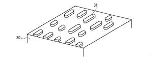
最初に、図1を用いて本実施の形態における光情報記録媒体(光ディスク)1の概略的な構造について説明を行う。図1は、本実施の形態における光情報記録媒体1の断面構造を示す図である。図1に示すように、光情報記録媒体1は、透光層10、情報記録層20、および基板30を備えており、光(再生光)の入射する側Aから、透光層10、情報記録層20、基板30の順に積層されている。なお、透光層10は、BD(Blu-ray Disc)などでカバー層と一般的に呼ばれるものである。
First, the schematic structure of the optical information recording medium (optical disk) 1 in the present embodiment will be described with reference to FIG. FIG. 1 is a diagram showing a cross-sectional structure of an optical information recording medium 1 in the present embodiment. As shown in FIG. 1, the optical information recording medium 1 includes a light-transmitting
まず、透光層10は、透明な樹脂によって形成されているものである。なお、透光層10は、再生光を十分に透過するものであればよく、紫外線硬化樹脂などによって形成されていてもよい。透光層10に用いることのできる樹脂材料としては、例えば、エポキシアクリレート、ウレタンアクリレート、ポリエステルアクリレート、フッ素化アクリル樹脂、およびエポキシ樹脂等がある。また、透光層10は、1層構成に限られるものではなく、ポリカーボネートフィルム等の透明樹脂フィルムと透明粘着樹脂層との2層構成としてもよい。他にも、透光層10の光入射面に、ハードコート層を設ける構成であってもよい。
First, the
また、透光層10の厚さとしては、透光層10が入射再生光の光軸に対して傾くことによって発生するコマ収差に対して、充分にチルトマージンを確保できるほどの薄さが必要となるとともに、情報記録層20を充分に保護できるだけの厚さが必要となる。なお、ここで言うところの透光層10の厚さとは、光情報記録媒体1の情報領域における透光層10の厚さの平均値を示すものとし、光情報記録媒体1枚1枚において固有の値である。また、後述の再生光学系(実施の形態2の光情報記録媒体再生装置100の光学系)においては、透光層10の厚さは69〜108μm程度であり、光情報記録媒体1が情報記録層20を1層有する(以降「単層」と表記する)ものである場合には、100μm程度であることがより望ましい。また、例えば光情報記録媒体1が情報記録層20を2層有する(以降「2層」と表記する)2層光情報記録媒体に適用する場合には、情報記録層20に対して、再生光が入射する側に位置する透光層10の厚さは、75μm程度であることが望ましい。
Further, the thickness of the
実際には、透光層10の望ましい厚さは、透光層10の屈折率の値に影響を受ける。透光層10に用いる上述の樹脂材料の一般的な屈折率は1.45〜1.70の範囲内であり、透光層10の屈折率が前記範囲内であれば、透光層10の望ましい厚さは、単層の場合で93〜108μm程度、2層の場合で69〜82μm程度となる。透光層10の厚さは、再生光学系におけるビームエクスパンダーまたはコリメータレンズの調整による球面収差補正によって設計変更することが可能であるため、少なくとも前記2層の下限値と前記単層の上限値との間、すなわち69〜108μmの範囲内であれば、再生光学系の球面収差調整で設計しておくことにより、充分に良好な再生が可能となる。なお、前記透光層10の厚さの範囲は、光情報記録媒体1が1枚1枚個々に持つ厚さ平均値の許容範囲であって、同一光情報記録媒体1内の情報領域全面において許される厚さ範囲ではない。同一光情報記録媒体1内においては、媒体回転時の再生光学系の一般的な再生能力およびサーボ能力を考慮して、透光層10の厚さが、情報領域において平均値±3μmの範囲内であることが望ましい。
Actually, the desired thickness of the
なお、本実施の形態における再生光としては、具体的には青紫色に該当する波長(375〜491nm)のものを用いるものとし、好ましくは400nm以上410nm以下のものを用いるものとする。また、対物レンズの開口数は0.84以上かつ0.86以下のものを用いるものとする。 Note that, specifically, the reproduction light in the present embodiment has a wavelength (375 to 491 nm) corresponding to bluish purple, and preferably has a wavelength of 400 nm to 410 nm. The numerical aperture of the objective lens is 0.84 or more and 0.86 or less.
続いて、基板30は、図2に示されるように、記録情報に対応した凹凸形状のプリピット(ピット)31が、同心円状、または、スパイラル状に形成されているものである。基板30を構成する材料の光学的特性は、特に限定されるものではなく、透明でも不透明であってもよい。基板30を構成する材料としては、例えば、ガラス、ポリカーボネート樹脂、圧縮型可能な他の樹脂、金属等、およびそれらの組合せが挙げられる。
Subsequently, as shown in FIG. 2, the
なお、情報記録層20に接する側にあたる基板30の面にプリピット31が形成されており、プリピット31が形成されている面に情報記録層20が成膜されることにより、情報記録層20にプリピット31が凹凸形状として転写された状態となっている。従って、光情報記録媒体1は、情報記録層20が、凹凸形状としての情報を記録している状態になっており、いわゆる再生専用光情報記録媒体として形成されている。
A
続いて、情報記録層20は、再生膜21および反射膜22を含んだものである。なお、再生膜21および反射膜22は、図1に示すように、光(再生光)の入射する側Aから、再生膜21、反射膜22の順に積層されている。すなわち、光(再生光)の入射する側Aから透光層10、再生膜21、反射膜22、基板30の順に積層されている。
Subsequently, the
まず、反射膜22は、主に2つの役割を持っているものである。1つは、再生光の一部を吸収して、再生膜21を加熱する熱に変換する役割であり、もう1つは、再生光を反射して、反射光による信号再生に用いることができるようにする役割である。
First, the
また、再生膜21は、反射膜22で生じる熱によって加熱されることにより、自身の光学定数が変化することによって、再生光学系の解像限界(再生光の回折限界で決まる光学的分解能)よりも短いマーク(ピット)長の信号の再生を可能にするものである。より、詳しくは、再生膜21は、温度が上昇することによって、再生光の波長における光学定数である、屈折率および/または消衰係数を変化させることにともなって、光学多重干渉の状態を変化させるものである。再生膜21の作用については、例えば以下のように説明を行うことができる。
Further, the reproducing
再生光が集光されて形成された再生ビームスポットでは、光強度分布によってスポット中心と外周部とで温度分布の偏りが生じる。実際には、再生ビームスポットが光情報記録媒体1を走査しているため、高温中心は再生ビームスポットの進行方向に対して後方側にずれ、再生ビームスポット内で温度勾配が発生する。つまり、再生ビームスポットの進行方向に向かって後方側に高温部が発生し、前方側に低温部が発生する。再生膜21が温度に応じて屈折率が変化するものとすると、再生ビームの入射によって温度が上昇した高温部では、再生膜21の屈折率が変化した状態となる。よって、情報記録層20の光干渉構造を予め設計しておくことによって、情報記録層20として、例えば高反射率の状態に変化するようにできる。一方、低温部では、再生膜21の屈折率が初期状態を維持しているため、高温部に比べると情報記録層20が低反射率の状態となる。このような、再生ビームスポット内における情報記録層20の反射率分布を積極的に利用することによって、再生領域のサイズを再生ビームスポットより実質的に小さくすることができ、再生分解能を向上させることができる。そして、再生分解能を向上させることによって、超解像再生を可能にする。
In the reproduction beam spot formed by collecting the reproduction light, the temperature distribution is biased between the spot center and the outer periphery due to the light intensity distribution. Actually, since the reproducing beam spot scans the optical information recording medium 1, the high temperature center is shifted backward with respect to the traveling direction of the reproducing beam spot, and a temperature gradient is generated in the reproducing beam spot. That is, a high temperature portion is generated on the rear side and a low temperature portion is generated on the front side in the traveling direction of the reproduction beam spot. Assuming that the refractive index of the reproducing
以上のことから、再生膜21は、熱によるバンドギャップ変化によって光学特性が変化する特性を有する金属酸化膜からなることが好ましい。これにより、通常の組成変化または相変化などの構造変化によって光学特性が変化する色素もしくは相変化材料を用いる形式の超解像再生光情報記録媒体における再生膜と比較して、再生膜21の再生耐久性を向上させることができる。また、金属酸化膜は透明のものが多く、反射膜22への透過性がよく、反射膜22がより効率的に作用するという利点もある。
From the above, it is preferable that the reproducing
また、再生膜21に適用するものとしては、金属酸化膜の中でも、特に比較的安価で豊富な酸化亜鉛が好ましいので、前記再生膜21は酸化亜鉛からなること、または酸化亜鉛を含むことが好ましい。以上の構成によれば、光情報記録媒体1のコストを低減することが可能になる。また、酸化亜鉛または酸化亜鉛を含む材料から再生膜21を構成することによって、他の金属酸化膜を用いるよりも高い超解像特性を得ることができるため、光情報記録媒体1の記録容量を向上させることが可能になる。さらに、作製が容易で大量生産が可能であるとともに、経時変化も起こりにくく再生耐久性を向上させりことが可能である。
Further, among the metal oxide films, zinc oxide that is relatively inexpensive and abundant is preferable as the material applied to the reproducing
また、酸化亜鉛以外の他の金属酸化物、例えばTiO2(酸化チタン)、CeO2(酸化セリウム)、またはSrTiO3(チタン酸ストロンチウム)からなる材料、もしくは当該材金属酸化物を主として含む材料にて、前記再生膜21を形成することも可能である。なお、この場合でも、酸化亜鉛からなる再生膜21および酸化亜鉛を含む材料からなる再生膜21と同等の再生耐久性を有する。
In addition, a metal oxide other than zinc oxide, such as TiO2 (titanium oxide), CeO2 (cerium oxide), or SrTiO3 (strontium titanate), or a material mainly containing the metal oxide, It is also possible to form the
また、反射膜22の材料としては、ある程度の反射率を有し、熱伝導率が低く、かつ安定な材料、例えばチタン(Ti)またはタンタル(Ta)などの金属が好ましい。これにより、反射膜22が再生光の一部を吸収しても、熱伝導率が低いので膜面方向の放熱量が比較的少なく、膜法線方向に位置する再生膜21への熱伝導を比較的効率よく行うことが可能になる。これに対し、従来までの光情報記録媒体の反射膜に一般的に用いられるAlまたはAgなどの材料は、反射率が高く、熱伝導率が高い。よって、従来までの反射膜を用いた場合には再生光を充分に吸収することができず、本願における超解像再生動作を行うだけの充分な熱量を得ることができない。従って、超解像再生パワー感度が悪くなる。また、従来までの反射膜を用いた場合には、熱伝導率が高すぎるため、反射膜における膜面方向の放熱量が大きくなり、膜法線方向に位置する再生膜21への熱伝導効率が悪くなる。よって、本願における超解像再生動作を行うだけの充分な熱量を再生膜21へ与えることができず、超解像再生パワー感度が悪くなる。
The material of the
以上のように、本実施の光情報記録媒体1は、情報記録層20において、再生光を一部吸収して発熱する反射膜22と、反射膜22による加熱で加熱部分の光学定数を変化させる再生膜21とを備えている。また、本実施の光情報記録媒体1では、情報記録層20に記録された情報を再生するときに、再生光が透光層10を通して照射されて情報記録層20にフォーカスされる。そして、情報記録層20においては、反射膜22が再生光を吸収することで光を熱に変換し、変換した熱を再生膜21に伝達する。ただし、光情報記録媒体1は、光情報記録媒体再生装置での再生時に回転しているので、再生膜21についての説明で述べたように、光強度分布と媒体回転に起因する温度分布の偏りによって、ビームスポットの後端部の温度が高くなる。すなわち、温度が高い位置がスポット中心からずれる。なお、温度が高い位置がスポット中心からずれることにより、高温領域の再生膜21の透過率が変化し、情報記録層20の解像限界以下のマーク(ピット)長で記録された情報を読み出すことができるようになる。そして、その結果、情報記録層20の実質的な記録密度(再生可能な記録密度)を、解像限界により規制された記録密度よりも高めることが可能になる。他にも、記録密度を高めるために多層化などを行う必要がなくなるので、記録媒体の製造コストを大幅に低減させながらも記録密度を高めることが可能になる。
As described above, in the optical information recording medium 1 of the present embodiment, in the
さらに、光情報記録媒体1では、再生膜21と反射膜22とをそれぞれ分離形成し、再生膜21と反射膜22とで光吸収し発熱する機能と光学特性を変化させる機能とを分担しているので、再生膜21自体が光吸収し発熱した上で光学特性を変化させて超解像再生を実現する必要がない。よって、再生膜21に多くの負担をかけることなく超解像再生を行うことが可能となり、再生膜21の耐久性を向上させることができる。また、再生膜21と反射膜22とで光吸収し発熱する機能と光学特性を変化させる機能とを分担するので、再生膜21に対しての機能性要求を少なくすることができ、材料設計の自由度を高くすることが可能になる。
Further, in the optical information recording medium 1, the reproducing
次に、本実施の形態における光情報記録媒体1と従来の光情報記録媒体との各種特性の比較についての説明を行う。以降では、最初に、本実施の形態における光情報記録媒体1の実施例1と従来の光情報記録媒体の比較例1、比較例2との各種特性の比較についての説明を行う。 Next, a comparison of various characteristics between the optical information recording medium 1 in the present embodiment and the conventional optical information recording medium will be described. Hereinafter, first, comparison of various characteristics between Example 1 of the optical information recording medium 1 in the present embodiment and Comparative Examples 1 and 2 of the conventional optical information recording medium will be described.
(実施例1)
まず、本実施の形態における光情報記録媒体1の実施例1について説明を行う。実施例1における光情報記録媒体1は、透光層10として、ポリカーボネートフィルム(膜厚:約80μm)および透明粘着樹脂層(膜厚:約20μm)を備え、情報記録層20として、酸化亜鉛からなる再生膜21(膜厚:60nm)およびタンタル(Ta)からなる反射膜22(膜厚:7nm)を備え、基板30として、ポリオレフィン系樹脂基板を備えている。また、実施例1における光情報記録媒体1は、図1にも示すように、光(再生光)の入射する側Aから、透光層10、情報記録層20、基板30の順に積層された構造になっている。より詳細には、ポリカーボネートフィルム、透明粘着樹脂層、酸化亜鉛、タンタル(Ta)、ポリオレフィン系樹脂の順に積層された構造となっている。Example 1
First, Example 1 of the optical information recording medium 1 in the present embodiment will be described. The optical information recording medium 1 in Example 1 includes a polycarbonate film (film thickness: about 80 μm) and a transparent adhesive resin layer (film thickness: about 20 μm) as the
なお、ここで、再生膜21および反射膜22の膜厚は、後に示す測定条件にてbER(Bit Error Rate)特性が最良となるよう最適化している。また、透光層10を構成するポリカーボネートフィルムおよび透明粘着樹脂層の2層のうち、ポリカーボネートフィルムと再生膜21との間に位置する透明粘着樹脂層は、ポリカーボネートフィルムと再生膜21とを接着する働きも担っている。透光層10の厚さは、100±3μmの範囲内であり、後述する比較例1、比較例2、実施例2、実施例3の透光層10においても同様のものとする。
Here, the film thicknesses of the
実施例1における光情報記録媒体1の作製方法としては、例えば、以下のような方法が挙げられる。まず、プリピット31が設けられた基板30にスパッタリングにより反射膜22、再生膜21を順に形成し、最後に透光層10(具体的にはポリカーボネートフィルムと透明粘着樹脂層からなる積層構造)を再生膜21に接着して作製を行う。なお、前記スパッタリングのターゲットとしては、酸化亜鉛として純度99.99%の酸化亜鉛焼結ターゲット、タンタルとして純度99.99%のTaターゲットを用い、各ターゲットをそれぞれRFマグネトロンスパッタ、DCマグネトロンスパッタすることによって成膜を行った。
Examples of the method for producing the optical information recording medium 1 in Example 1 include the following methods. First, the
また、実施例1におけるプリピット31は、評価用にランダムパターンとモノトーンパターンとが設けられている。
Further, the
まず、ランダムパターン(RLL(1,7)変調方式によって複数の長さを有するマークおよびスペースとして形成されているパターン、所定の変調方式(RLL(1,7)変調方式、ETM(8/12)変調方式など)によって複数の長さを有するマークおよびスペースとして形成されているパターン)については、BDの規格と同様のRLL(1,7)変調方式に準拠して形成されており、データ領域の最短マークは2T(マーク長93nm)であり、最長マークは8Tである。また、2Tプリピット(93nm)および2Tスペースは、後述の評価光学系(ディスク測定器の光学系)の解像限界(λ/(4NA)=0.12μm)以下のサイズである。なお、通常の光情報記録媒体(超解像再生機能を有さない光情報記録媒体、以下では非超解像媒体と表記する)の場合では、上述の評価光学系の解像限界以下のサイズのピットおよびスペースが隣接したパターンは、上述の評価光学系では検出できず、再生が不可能である。なお、このランダムパターンのうち、2Tのみが評価光学系の解像限界以下のサイズであり、それ以外のプリピット(3T、4T、...、8T)は、すべて上述の評価光学系の解像限界よりも大きなサイズである。 First, a random pattern (a pattern formed as a mark and a space having a plurality of lengths by the RLL (1, 7) modulation method, a predetermined modulation method (RLL (1, 7) modulation method, ETM (8/12) The pattern formed as a mark and a space having a plurality of lengths by a modulation method, etc.) is formed in accordance with the RLL (1, 7) modulation method similar to the BD standard, The shortest mark is 2T (mark length 93 nm), and the longest mark is 8T. Further, the 2T prepit (93 nm) and the 2T space have a size equal to or smaller than the resolution limit (λ / (4NA) = 0.12 μm) of the later-described evaluation optical system (the optical system of the disk measuring device). In the case of a normal optical information recording medium (an optical information recording medium having no super-resolution reproduction function, hereinafter referred to as a non-super-resolution medium), the size is equal to or smaller than the resolution limit of the evaluation optical system described above. The pattern having adjacent pits and spaces cannot be detected by the above-described evaluation optical system and cannot be reproduced. Of the random pattern, only 2T has a size less than or equal to the resolution limit of the evaluation optical system, and all other prepits (3T, 4T,..., 8T) are resolved by the above-described evaluation optical system. The size is larger than the limit.
なお、光情報記録媒体1(具体的には情報記録層20)上に記録マークが形成される状態をマークと言い、記録マークが形成されない状態をスペースと言う。また、Tは信号波形の時間軸における基準クロック1周期分の時間を表しており、例えば記録マーク長が2Tの場合には、基準クロック2周期分の時間に相当する記録マークが形成される記録領域を表すことになる。 A state where a recording mark is formed on the optical information recording medium 1 (specifically, the information recording layer 20) is called a mark, and a state where no recording mark is formed is called a space. T represents a time corresponding to one cycle of the reference clock on the time axis of the signal waveform. For example, when the recording mark length is 2T, a recording mark corresponding to a time corresponding to two cycles of the reference clock is formed. It represents the area.
また、モノトーンパターンについては、CNR(carrier-to-noise ratio、搬送波対雑音比)測定用に2Tマーク(マーク長93nm)、2Tスペースの連続からなるように形成している(2Tモノトーンパターン)。 Further, the monotone pattern is formed so as to consist of a continuous 2T mark (mark length 93 nm) and 2T space for CNR (carrier-to-noise ratio) measurement (2T monotone pattern).
(比較例1)
これに対して、図3に、実施例1の光情報記録媒体1に対する比較例1として、光情報記録媒体2の概略的な断面構造を示す。なお、比較例1において、実施例1の光情報記録媒体1における構成要素と同等の機能を有する構成要素については、同一の符号を付記し、その説明を省略する。(Comparative Example 1)
In contrast, FIG. 3 shows a schematic cross-sectional structure of an optical
図3に示すように、比較例1の光情報記録媒体2は、透光層10として、ポリカーボネートフィルム(膜厚:約80μm)および透明粘着樹脂層(膜厚:約20μm)を備え、情報記録層40として、酸化亜鉛からなる再生膜41(膜厚:78nm)およびシリコン(Si)からなる反射膜42(膜厚:7nm)を備え、基板30として、ポリオレフィン系樹脂基板を備えている。また、比較例1における光情報記録媒体2は、図3にも示すように、光(再生光)の入射する側Aから、透光層10、情報記録層40、基板30の順に積層された構造になっている。より詳細には、ポリカーボネートフィルム、透明粘着樹脂層、酸化亜鉛、シリコン(Si)、ポリオレフィン系樹脂の順に積層された構造となっている。
As shown in FIG. 3, the optical
なお、ここで、再生膜41および反射膜42の膜厚は、後に示す測定条件にてbER特性が最良となるよう最適化している。また、この時、比較例1の反射率が、実施例1の反射率とほぼ同様となることを確認している。なお、プリピットに形成されたパターンは、実施例1と同じものを使用している。
Here, the film thicknesses of the
(比較例2)
また、図4に、実施例1の光情報記録媒体1に対する比較例2として、光情報記録媒体3概略的な断面構造を示す。なお、比較例2においても、実施例1の光情報記録媒体1における構成要素と同等の機能を有する構成要素については、同一の符号を付記し、その説明を省略する。また、比較例2の光情報記録媒体3は、超解像再生可能な再生専用媒体として特許文献1に開示されている構成と同じ構成になっている。(Comparative Example 2)
FIG. 4 shows a schematic cross-sectional structure of the optical information recording medium 3 as a comparative example 2 with respect to the optical information recording medium 1 of the first embodiment. In Comparative Example 2 as well, components having functions equivalent to those of the components in the optical information recording medium 1 of Example 1 are denoted by the same reference numerals and description thereof is omitted. Further, the optical information recording medium 3 of Comparative Example 2 has the same configuration as that disclosed in Patent Document 1 as a reproduction-only medium capable of super-resolution reproduction.
図4に示すように、比較例2の光情報記録媒体3は、透光層10として、ポリカーボネートフィルム(膜厚:約80μm)および透明粘着樹脂層(膜厚:約20μm)を備え、情報記録層45として、シリコン(Si)からなる層(膜厚:50nm)を備え、基板30として、ポリオレフィン系樹脂基板を備えている。また、比較例2における光情報記録媒体3は、図4にも示すように、光(再生光)の入射する側Aから、透光層10、情報記録層45、基板30の順に積層された構造になっている。より詳細には、ポリカーボネートフィルム、透明粘着樹脂層、シリコン(Si)、ポリオレフィン系樹脂の順に積層された構造となっている。なお、プリピットに形成されたパターンは、実施例1と同じものを使用している。
As shown in FIG. 4, the optical information recording medium 3 of Comparative Example 2 includes a polycarbonate film (film thickness: about 80 μm) and a transparent adhesive resin layer (film thickness: about 20 μm) as the light-transmitting
また、比較例1の情報記録層40、および比較例2の情報記録層45は、基板30において情報が記録されているプリピット31の形成面に成膜されている。従って、実施例1の光情報記録媒体1と同様に、比較例1の光情報記録媒体2、および比較例2の光情報記録媒体3においても、情報記録層40および情報記録層45には、対応するプリピット31の凹凸が転写された状態となっている。すなわち、光情報記録媒体2および光情報記録媒体3も、光情報記録媒体1と同様に、いわゆる再生専用光情報記録媒体として形成されている。なお、一般のBDは、12cmのディスクに単層25GBの記録容量を有し、最短マーク2Tの長さは149nmである。従って、プリピット31は、前記25GB媒体と同じトラックピッチを採用した場合、12cmディスクに換算すると40GBとなる密度に相当する。
Further, the
続いて、実施例1の光情報記録媒体1と比較例1の光情報記録媒体2、比較例2の光情報記録媒体3との各種特性の比較をどのようにして行ったかについての説明を行う。
Next, description will be made on how various characteristics were compared between the optical information recording medium 1 of Example 1, the optical
まず、ディスク再生測定は、λ(波長)405nm半導体レーザーと、NA(開口率)0.85の光学系とを有するディスク測定器(パルステック社製DDU1000)にて行った。また、光情報記録媒体の実用化検討のために、記録すべきデータを変調してランダムパターンとして記録し、超解像再生特性を評価した。なお、本実施の形態では、実施例1と比較例1、比較例2とに共通のプリピット31を用いたため、上述のランダムパターンおよびモノトーンパターンの再生評価結果を比較することにより、両媒体(実施例1の光情報記録媒体1と比較例1の光情報記録媒体2、または実施例1の光情報記録媒体1と比較例2の光情報記録媒体3)の超解像再生特性を比較することができる。また、前記ディスク再生測定は、線速度3.1m/sにて行い、CNR、bERを信号評価指標とした。なお、ここで言うところのディスク再生測定とは、光情報記録媒体を回転させ、再生光を照射した後に、反射光を検出して再生信号波形を得て、信号を解析することを表している。
First, the disk reproduction measurement was performed with a disk measuring instrument (DDU1000 manufactured by Pulstec Corp.) having a λ (wavelength) 405 nm semiconductor laser and an optical system with NA (aperture ratio) 0.85. In addition, in order to examine the practical application of the optical information recording medium, the data to be recorded was modulated and recorded as a random pattern, and the super-resolution reproduction characteristics were evaluated. In the present embodiment, since the
以下では、各信号評価指標についての説明を行う。まず、CNRについては、上述の2Tモノトーンパターンのキャリア対ノイズ比(搬送波対雑音比)を測定した。これにより、実施例1、比較例1、比較例2の前記2Tモノトーンパターンの超解像再生性能を調べた。なお、CNRの値が高いほど、本評価光学系(ディスク測定器の光学系)の解像限界以下の2Tモノトーンパターンの信号品質が高いことに相当する。 Hereinafter, each signal evaluation index will be described. First, for CNR, the carrier-to-noise ratio (carrier-to-noise ratio) of the 2T monotone pattern described above was measured. Thus, the super-resolution reproduction performance of the 2T monotone pattern of Example 1, Comparative Example 1, and Comparative Example 2 was examined. The higher the CNR value, the higher the signal quality of the 2T monotone pattern below the resolution limit of this evaluation optical system (the optical system of the disk measuring device).
続いて、bERは、ビット誤り率とも言い、光情報記録媒体に記録された上述のランダムパターンを再生した信号を復号した結果に含まれるエラービット数Neの、全復号ビット数Ntに対する比率である。すなわち、bER=Ne/Ntである。なお、bERは、光情報記録媒体におけるランダムパターンの信号品質の評価指標として一般的に用いられており、bER値が大きくなることは、本来の記録データを信頼性高く再生できないことに相当する。より詳しくは、bER値が大きくなると、具体的にはノイズおよび音とびが生ずるなど、光情報記録媒体からの再生信号の品質が劣化することになる。 Subsequently, bER is also referred to as a bit error rate, and is a ratio of the number of error bits Ne included in the result of decoding the signal obtained by reproducing the random pattern recorded on the optical information recording medium to the total number of decoded bits Nt. . That is, bER = Ne / Nt. Note that bER is generally used as an evaluation index of signal quality of a random pattern in an optical information recording medium, and a large bER value corresponds to the fact that original recording data cannot be reproduced with high reliability. More specifically, when the bER value increases, the quality of the reproduction signal from the optical information recording medium deteriorates, specifically, noise and sound skipping occur.
本実施の形態では、前記ディスク測定器で取得した信号波形に対して、PR(12221)ML復号を行い、正解パターンを用いてbERを求めた。なお、PR(12221)ML復号については、高密度記録された光情報記録媒体の再生に用いられるものとして知られている。また、等化係数は等化後波形とPR(12221)ML理想波形との平均二乗誤差が最小となるものをそれぞれ用いた。なお、この等化係数の最適化方法は、平均二乗誤差(LMS:Least Mean Square)アルゴリズムと言い、PRML復号においてよく用いられる方法である。 In the present embodiment, PR (12221) ML decoding is performed on the signal waveform acquired by the disk measuring device, and bER is obtained using the correct pattern. The PR (12221) ML decoding is known to be used for reproducing an optical information recording medium recorded with high density. As the equalization coefficient, the one that minimizes the mean square error between the equalized waveform and the PR (12221) ML ideal waveform was used. This equalization coefficient optimization method is called a Least Mean Square (LMS) algorithm, and is a method often used in PRML decoding.
本実施の形態では、上述のようにして求めたbERにより、実施例1、比較例1、比較例2の前記ランダムパターンの超解像再生特性を比較した。なお、bERが低いほど、本実施の形態の評価光学系の解像限界以下の2T信号を含むランダムパターンの信号品質が高いことを表している。一般に、得られたbERについて、実用上問題がないか否かの判定のためには、光情報記録媒体再生装置で採用されている誤り訂正方式によって決まる閾値が用いられる。なお、前記閾値としては、本実施の形態では、3E−4を用いている。3E−4については、非特許文献3において、実用上問題ない再生時のビット誤り率として記載されている。従って、3E−4以下のbERであれば、誤りがあったとしても誤りの訂正が可能であるため、実用上問題がないと言える。以降では、特に断らない限り、3E−4という値をbERの閾値(以下、単に、「閾値」または「実用化閾値」という場合がある)とする。 In the present embodiment, the super-resolution reproduction characteristics of the random patterns of Example 1, Comparative Example 1, and Comparative Example 2 were compared based on the bER obtained as described above. Note that the lower the bER, the higher the signal quality of the random pattern including the 2T signal below the resolution limit of the evaluation optical system of the present embodiment. In general, for the obtained bER, a threshold value determined by an error correction method employed in the optical information recording medium reproducing device is used to determine whether or not there is a practical problem. As the threshold value, 3E-4 is used in the present embodiment. 3E-4 is described in Non-Patent Document 3 as a bit error rate at the time of reproduction with no practical problem. Therefore, if the bER is 3E-4 or lower, even if there is an error, it can be corrected, so it can be said that there is no practical problem. Hereinafter, unless otherwise specified, a value of 3E-4 is set as a threshold value of bER (hereinafter, simply referred to as “threshold value” or “practical use threshold value”).
続いて、図5および図6を用いて、実施例1、比較例1、比較例2の前記ランダムパターンの超解像再生特性を比較した結果についての説明を行う。なお、図5は、実施例1、比較例1、比較例2の各光情報記録媒体(光情報記録媒体1、光情報記録媒体2、光情報記録媒体3)におけるCNRの再生パワーPr依存性を示す特性図である。また、図6は、実施例1、比較例1、比較例2の各光情報記録媒体(光情報記録媒体1、光情報記録媒体2、光情報記録媒体3)におけるbERの再生パワーPr依存性を示す特性図である。
Next, the results of comparing the super-resolution reproduction characteristics of the random patterns of Example 1, Comparative Example 1, and Comparative Example 2 will be described with reference to FIGS. 5 and 6. 5 shows the dependency of CNR on the reproduction power Pr in each of the optical information recording media (optical information recording medium 1, optical
まず、図5を用いて、上述のディスク測定器にて、前記2Tモノトーンパターンを持つ実施例1、比較例1、比較例2の各光情報記録媒体(光情報記録媒体1、光情報記録媒体2、光情報記録媒体3)における、CNRの再生パワーPr依存性を測定した結果の説明を行う。 First, referring to FIG. 5, each of the optical information recording media (optical information recording medium 1, optical information recording medium) of Example 1, Comparative Example 1, and Comparative Example 2 having the 2T monotone pattern with the above-described disk measuring device is used. 2, the result of measuring the dependency of CNR on the reproduction power Pr in the optical information recording medium 3) will be described.
図5に示す測定結果から明らかなように、2TモノトーンパターンのCNRは、実施例1、比較例1、比較例2のいずれの光情報記録媒体においても、再生パワーが高くなるにつれて上昇している。具体的には、再生パワー1.0mW付近で10dB以上を示し、それ以上のパワーでCNRがさらに上昇し、いずれの光情報記録媒体(光情報記録媒体1、光情報記録媒体2、光情報記録媒体3)でも実用化の目安といわれる30dB以上を実現している。このことは、実施例1、比較例1、比較例2のいずれにおいても、再生パワーが高くなることによって2Tモノトーンパターンの信号振幅が増加し、信号品質が向上していることを表している。
As is apparent from the measurement results shown in FIG. 5, the CNR of the 2T monotone pattern increases as the reproduction power increases in any of the optical information recording media of Example 1, Comparative Example 1, and Comparative Example 2. . Specifically, it shows 10 dB or more near a reproduction power of 1.0 mW, and the CNR further increases at a power higher than that, and any of the optical information recording media (optical information recording medium 1, optical
続いて、図6を用いて、上述のディスク測定器にて、前記ランダムパターンを持つ実施例1、比較例1の各光情報記録媒体(光情報記録媒体1、光情報記録媒体2)における、bERの再生パワーPr依存性を測定した結果の説明を行う。なお、信号品質が悪く、測定が良好に行えなかった結果に関しては図6の特性図にプロットを行っていない。また、比較例2については、正しくクロックを生成することが出来なかったため、正しいサンプリング間隔で再生信号波形をデジタル化することが出来ず、bER評価の可能なサンプリング信号を得ることが出来なかった。ただし、クロック生成には、再生信号波形を用いる内部クロック方式を用いた。すなわち、比較例2は信号品質が悪く、この密度におけるランダムパターンを良好に再生することができなかった。 Subsequently, with reference to FIG. 6, in each of the optical information recording media (optical information recording medium 1 and optical information recording medium 2) of Example 1 and Comparative Example 1 having the random pattern, using the disk measuring device described above. The result of measuring the dependence of bER on the reproduction power Pr will be described. Note that no plot is made in the characteristic diagram of FIG. 6 for the results of poor signal quality and poor measurement. In Comparative Example 2, since the clock could not be generated correctly, the reproduced signal waveform could not be digitized at the correct sampling interval, and a sampling signal capable of bER evaluation could not be obtained. However, an internal clock method using a reproduced signal waveform was used for clock generation. That is, the signal quality in Comparative Example 2 was poor, and the random pattern at this density could not be reproduced well.
図6に示す測定結果から明らかなように、実施例1の光情報記録媒体1では、比較例1の光情報記録媒体2に比べて、所定の再生パワー(この場合は0.8mW)以上では、それぞれ同再生パワーにおけるbER値が低くなり、解像限界以下の2Tマークおよび2Tスペースを含むランダムパターンの超解像再生特性、つまり検出能力が向上している。上述のbER実用化閾値3E−4を考慮すると、実施例1の光情報記録媒体では、前記所定の再生パワー以上で閾値以下を満足している。ここでは、前記所定の再生パワーを0.8mWとしたが、前記所定の再生パワー未満、例えば再生パワー0.6mWにおいてbERが閾値よりも大きくなってしまう理由は以下のように考えられる。すでに説明したように、光情報記録媒体1では超解像再生を行うために、再生膜21を再生ビームスポット内において昇温させる必要があるが、bERを見る限り、0.6mWでは閾値より大きく、超解像再生に必要な再生パワーが投入されていないと言える。すなわち、再生パワー0.6mWは、実施例1の光情報記録媒体1の超解像再生に必要な再生パワーを満たしていないためと考えられる。
As is apparent from the measurement results shown in FIG. 6, the optical information recording medium 1 of Example 1 has a predetermined reproduction power (in this case, 0.8 mW) or more as compared with the optical
図5に示した2TモノトーンパターンのCNRは、再生パワー0.6mWで5dB程度、0.8mWで10dB以上となる。また、bER評価から、再生パワー0.8mWでは高品質の超解像再生が実現できることが明らかであるため、2TモノトーンパターンのCNRが10dB得られる程度の再生パワー以上で再生すれば、実施例1の光情報記録媒体1において高品質の超解像再生が実現できることが判る。これに対し、比較例1では、ほぼすべての再生パワーにおいて閾値よりもbERが高くなっている。実際には、局部的にbERが閾値を下回る再生パワーも存在するが、非常に狭い範囲であって、再生パワーマージンがほとんどなく、事実上、比較例1の実用化は困難であることが判る。 The CNR of the 2T monotone pattern shown in FIG. 5 is about 5 dB at a reproduction power of 0.6 mW and 10 dB or more at 0.8 mW. Also, from the bER evaluation, it is clear that high-quality super-resolution reproduction can be realized with a reproduction power of 0.8 mW. Therefore, if reproduction is performed with a reproduction power of such a degree that a CNR of a 2T monotone pattern is 10 dB, Embodiment 1 It can be seen that high-quality super-resolution reproduction can be realized in the optical information recording medium 1. On the other hand, in Comparative Example 1, bER is higher than the threshold value in almost all reproduction powers. Actually, there is a reproduction power whose bER is locally lower than the threshold value, but it is in a very narrow range and there is almost no reproduction power margin, and it can be seen that practical use of Comparative Example 1 is actually difficult. .
以上、図5および図6の結果から、次のことが言える。 From the results shown in FIGS. 5 and 6, the following can be said.
まず、実施例1、比較例1、比較例2のいずれにおいても、所定の再生パワーを与えれば、2TモノトーンパターンのCNRが30dBと高くなり、本評価光学系の解像限界以下の、2Tモノトーンパターンの信号品質が高くなる。しかしながら、ランダムパターンのbER評価では、比較例2では評価不可、比較例1では概ね閾値3E−4以上であり、実用には適さない。これに対して、実施例1のみが、所定の再生パワー以上で閾値3E−4以下を満足し、本評価光学系の解像限界以下の2Tマークおよび2Tスペースを含むランダムパターンの信号品質が高くなっている。本実施の形態でbER評価に用いたランダムパターンは、モノトーンパターンよりも光情報記録媒体の実用化に、より近い形であり、実際に使用が想定される数種のマーク長のピットおよびスペースからなる。すなわち、実施例1の光情報記録媒体1の構成によれば、本評価光学系の解像限界以下の最短マークおよび最短スペースを含むランダムパターンの実用化が可能となる。 First, in any of Example 1, Comparative Example 1, and Comparative Example 2, when a predetermined reproduction power is applied, the CNR of the 2T monotone pattern increases to 30 dB, and the 2T monotone below the resolution limit of this evaluation optical system. The signal quality of the pattern is increased. However, in the bER evaluation of the random pattern, the evaluation in Comparative Example 2 is not possible, and the Comparative Example 1 is generally more than the threshold 3E-4, which is not suitable for practical use. On the other hand, only Example 1 satisfies the threshold 3E-4 or less above the predetermined reproduction power, and the signal quality of the random pattern including the 2T mark and the 2T space below the resolution limit of the present evaluation optical system is high. It has become. The random pattern used for the bER evaluation in this embodiment is closer to the practical use of the optical information recording medium than the monotone pattern, and is based on pits and spaces of several mark lengths that are actually assumed to be used. Become. That is, according to the configuration of the optical information recording medium 1 of Example 1, a random pattern including the shortest mark and the shortest space below the resolution limit of the evaluation optical system can be put into practical use.
また、非特許文献1ですでに示したように、Super−RENSなどの従来例では、ランダムパターンの超解像再生を行うにあたってPRML信号復号方式を進歩させた信号処理が必要であったが、実施例1のような構成であれば、汎用性が高く比較的安価なPR(12221)MLの復号によっても、信頼性の高い超解像再生が可能である。また、汎用性が高く比較的安価なPR(12221)MLの復号によっても、信頼性の高い超解像再生が可能であるので、低コスト、低消費電力にて超解像再生が可能になり、実用化が可能となる。 In addition, as already shown in Non-Patent Document 1, in the conventional example such as Super-RENS, signal processing that advances the PRML signal decoding method is necessary to perform super-resolution reproduction of a random pattern. With the configuration of the first embodiment, highly reliable super-resolution reproduction is possible even by decoding PR (12221) ML, which is highly versatile and relatively inexpensive. In addition, highly reliable and relatively inexpensive PR (12221) ML decoding also enables highly reliable super-resolution reproduction, thus enabling super-resolution reproduction with low cost and low power consumption. It becomes possible to put it into practical use.
なお、反射膜22の膜厚を実施例1の7nmから変更した、反射膜22の膜厚が4nmの光情報記録媒体と15nmの光情報記録媒体とを作製し、実施例1の光情報記録媒体に行ったのと同様の評価を行ったところ、実施例1と同様のCNR、bERの結果が得られた。すなわち、反射膜22の膜厚は7nmに限定されるものではなく、少なくとも4nm以上かつ15nm以下の範囲内で、実施例1と同様の超解像再生特性を実現するものである。
In addition, the optical information recording medium in which the film thickness of the
また、本実施の形態では、光情報記録媒体1に情報記録層20を1層有する構成について示したが、必ずしもこれに限らず、コストと記録容量とのバランスがとれるならば、光情報記録媒体1に情報記録層20を2層以上有する構成としてもよい。
In the present embodiment, the configuration in which the optical information recording medium 1 has one
なお、本発明は、記録の方式および記録容量の大きさを問うものではない。よって、光情報記録媒体1の構成を、CD−ROM(Compact Disc Read Only Memory)、DVD−ROM(Digital Versatile Disc Read Only Memory)、BD−ROM(Blu-ray Disc Read Only Memory)、HD DVD−ROM(High Definition Digital Versatile Disc Read Only Memory)等の光学読取式のディスクなど、種々の光ディスクに適用することが可能である。また、CD−R、DVD−R、BD−R、HD DVD−R、およびCD−RW、DVD−RW、BD−RE、HD DVD−RW、CD+RW、DVD+RW、DVD−RAM、HD DVD−RAMなどの追記可能または書き換え可能な光情報記録媒体などに、本実施の形態の再生膜21、反射膜22を適用することで、本願技術を適用することも可能である。例えば、光入射側から順に、再生膜21、反射膜22に加えて、追記可能または書き換え可能な記録膜を設ける構成とすることも可能である。また、光入射側から順に、再生膜21、前記追記可能または書き換え可能な記録膜を設け、反射膜22の役割を前記追記可能または書き換え可能な記録膜が兼ねる構成とすることも可能である。
In the present invention, the recording method and the recording capacity are not questioned. Therefore, the configuration of the optical information recording medium 1 is composed of CD-ROM (Compact Disc Read Only Memory), DVD-ROM (Digital Versatile Disc Read Only Memory), BD-ROM (Blu-ray Disc Read Only Memory), HD DVD-. The present invention can be applied to various optical disks such as optically readable disks such as ROM (High Definition Digital Versatile Disc Read Only Memory). Also, CD-R, DVD-R, BD-R, HD DVD-R, CD-RW, DVD-RW, BD-RE, HD DVD-RW, CD + RW, DVD + RW, DVD-RAM, HD DVD-RAM, etc. By applying the reproducing
次に、図7および図8を用いて、本実施の形態における光情報記録媒体1の実施例1以外の実施例に対して行った各種特性の評価についての説明を行う。以降では、本実施の形態における光情報記録媒体1の実施例2と実施例3とに対して行った各種特性の評価についての説明を行う。なお、実施例2および実施例3の光情報記録媒体の膜構造は、実施例1の光情報記録媒体1の膜構造と同様であり、情報記録層20に用いる材料が異なる以外は、光情報記録媒体の作製方法、成膜方法なども実施例1で説明したのと同様である。
Next, with reference to FIG. 7 and FIG. 8, the evaluation of various characteristics performed on examples other than Example 1 of the optical information recording medium 1 in the present embodiment will be described. In the following, the evaluation of various characteristics performed on Example 2 and Example 3 of the optical information recording medium 1 in the present embodiment will be described. The film structures of the optical information recording media of Example 2 and Example 3 are the same as the film structure of the optical information recording medium 1 of Example 1, except that the material used for the
(実施例2)
まず、本実施の形態における光情報記録媒体1の実施例2について説明を行う。実施例2における光情報記録媒体1は、実施例1における光情報記録媒体1に対して、タンタル(Ta)の代わりにチタン(Ti)を用いた点を除いて、共通の構成からなっている。すなわち、実施例2における光情報記録媒体1は、実施例1における光情報記録媒体1に対して、Taからなる反射膜22(膜厚:7nm)の代わりに、Tiからなる反射膜22(膜厚:7nm)を有している。(Example 2)
First, Example 2 of the optical information recording medium 1 in the present embodiment will be described. The optical information recording medium 1 in Example 2 has the same configuration as that of the optical information recording medium 1 in Example 1 except that titanium (Ti) is used instead of tantalum (Ta). . That is, the optical information recording medium 1 in Example 2 is different from the optical information recording medium 1 in Example 1 in that the reflective film 22 (film) made of Ti is used instead of the reflective film 22 (film thickness: 7 nm) made of Ta. (Thickness: 7 nm).
(実施例3)
続いて、本実施の形態における光情報記録媒体1の実施例3について説明を行う。実施例3における光情報記録媒体1は、実施例1における光情報記録媒体1に対して、酸化亜鉛の代わりにチタン酸ストロンチウム(SrTiO3)を用いた点を除いて、共通の構成からなっている。すなわち、実施例3における光情報記録媒体1は、実施例1における光情報記録媒体1に対して、酸化亜鉛からなる再生膜21(膜厚:60nm)の代わりに、SrTiO3からなる再生膜21(膜厚:60nm)を有している。(Example 3)
Subsequently, Example 3 of the optical information recording medium 1 in the present embodiment will be described. The optical information recording medium 1 in Example 3 has the same configuration as the optical information recording medium 1 in Example 1 except that strontium titanate (SrTiO3) is used instead of zinc oxide. . That is, the optical information recording medium 1 in Example 3 is different from the optical information recording medium 1 in Example 1 in that a reproducing film 21 (SrTiO3) is used instead of the reproducing film 21 (thickness: 60 nm) made of zinc oxide. (Film thickness: 60 nm).
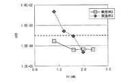
以上の実施例2、実施例3の光情報記録媒体に対して、実施例1の光情報記録媒体に対して行ったのと同様のCNR、bER評価を行った結果について、図7および図8を用いて説明を行う。なお、図7は、実施例2、実施例3の各光情報記録媒体におけるCNRの再生パワーPr依存性を示す特性図である。また、図8は、実施例2、実施例3の各光情報記録媒体におけるbERの再生パワーPr依存性を示す特性図である。 7 and 8 show the results of CNR and bER evaluation similar to those performed on the optical information recording medium of Example 1 for the optical information recording media of Example 2 and Example 3 described above. A description will be given using. FIG. 7 is a characteristic diagram showing the dependency of CNR on the reproduction power Pr in each of the optical information recording media of Example 2 and Example 3. FIG. 8 is a characteristic diagram showing the reproduction power Pr dependence of bER in each of the optical information recording media of Example 2 and Example 3.
まず、図7を用いて、上述のディスク測定器にて、前記2Tモノトーンパターンを持つ実施例2、実施例3の各光情報記録媒体における、CNRの再生パワーPr依存性を測定した結果の説明を行う。 First, with reference to FIG. 7, description will be given of the result of measuring the dependency of CNR on the reproduction power Pr in each of the optical information recording media of Examples 2 and 3 having the 2T monotone pattern by the above-described disk measuring device. I do.
図7に示す測定結果から明らかなように、2TモノトーンパターンのCNRは、実施例2、実施例3のいずれの光情報記録媒体においても、再生パワーが高くなるにつれて上昇している。具体的には、実施例2では再生パワー0.8mWで10dB以上を示し、それ以上のパワーでCNRがさらに上昇し、実用化の目安といわれる30dB以上を実現している。また、実施例3では再生パワー1.6mWで10dB以上を示し、それ以上のパワーでCNRがさらに上昇している。このことは、実施例2、実施例3のいずれにおいても、再生パワーが高くなることによって2Tモノトーンパターンの信号振幅が増加し、信号品質が向上していることを表している。 As is apparent from the measurement results shown in FIG. 7, the CNR of the 2T monotone pattern increases as the reproduction power increases in both the optical information recording media of Example 2 and Example 3. Specifically, the reproduction power of 0.8 mW is 10 dB or more in Example 2, and the CNR is further increased at a power higher than that, realizing 30 dB or more, which is said to be a practical standard. Further, in Example 3, the reproduction power is 1.6 mW and 10 dB or more is shown, and the CNR is further increased at a power higher than that. This indicates that in both the second and third embodiments, the signal amplitude of the 2T monotone pattern is increased and the signal quality is improved as the reproduction power is increased.
続いて、図8を用いて、上述のディスク測定器にて、前記ランダムパターンを持つ実施例2、実施例3の各光情報記録媒体における、bERの再生パワーPr依存性を測定した結果の説明を行う。なお、信号品質が悪く測定が良好に行えなかった結果に関してはプロットを行っていない。 Next, with reference to FIG. 8, description of the result of measuring the dependency of bER on the reproduction power Pr in each of the optical information recording media of Example 2 and Example 3 having the random pattern by the above-described disk measuring device. I do. It should be noted that no plot was made for the results of poor signal quality and poor measurement.
図8に示す測定結果から明らかなように、実施例2および実施例3の光情報記録媒体では、所定の再生パワー(実施例2の場合は0.8mW、実施例3の場合は1.6mW)以上では、それぞれ同再生パワーにおけるbER値が低くなり、解像限界以下の2Tマークおよび2Tスペースを含むランダムパターンの超解像再生特性、つまり検出能力が向上している。上述のbER実用化閾値3E−4を考慮すると、実施例2および実施例3の光情報記録媒体では、それぞれ所定の前記再生パワー以上で閾値以下を満足している。ここでは前記所定の再生パワーを、実施例2では0.8mW、実施例3では1.6mWとしたが、それぞれ前記所定の再生パワー未満ではbERが閾値よりも大きくなってしまう理由は、実施例1の場合と同様に以下のように考えられる。すでに説明したように、光情報記録媒体1では超解像再生を行うために、再生膜21を再生ビームスポット内において昇温させる必要があるが、bERを見る限り、各所定の再生パワー未満では閾値より大きく、超解像再生に必要な再生パワーが投入されていないと言える。すなわち、各所定の再生パワー未満(実施例2の場合は0.8mW未満、実施例3の場合は1.6mW未満)では、実施例2の光情報記録媒体1、実施例3の光情報記録媒体1のそれぞれの超解像再生に必要な再生パワーを満たしていないためと考えられる。
As is apparent from the measurement results shown in FIG. 8, in the optical information recording media of Examples 2 and 3, a predetermined reproduction power (0.8 mW in Example 2 and 1.6 mW in Example 3). In the above, the bER value at the same reproduction power is lowered, and the super-resolution reproduction characteristics of the random pattern including the 2T mark and the 2T space below the resolution limit, that is, the detection capability is improved. In consideration of the above-described bER practical use threshold value 3E-4, the optical information recording media of Example 2 and Example 3 each satisfy the threshold value not less than the predetermined reproduction power. Here, the predetermined reproduction power is set to 0.8 mW in the second embodiment and 1.6 mW in the third embodiment. The reason why the bER becomes larger than the threshold value below the predetermined reproduction power is as follows. As in the case of 1, it can be considered as follows. As described above, in the optical information recording medium 1, in order to perform super-resolution reproduction, it is necessary to raise the temperature of the reproducing
図7に示した2TモノトーンパターンのCNRは、各所定の再生パワー(実施例2の場合は0.8mW、実施例3の場合は1.6mW)で10dB以上となる。また、bER評価から、各所定の再生パワー(実施例2の場合は0.8mW、実施例3の場合は1.6mW)では高品質の超解像再生が実現できることが明らかであるため、2TモノトーンパターンのCNRが10dB得られる程度の再生パワー以上で再生すれば、実施例2および実施例3の光情報記録媒体1においても高品質の超解像再生が実現できることが判る。 The CNR of the 2T monotone pattern shown in FIG. 7 is 10 dB or more at each predetermined reproduction power (0.8 mW in the second embodiment and 1.6 mW in the third embodiment). Also, from the bER evaluation, it is clear that high-quality super-resolution reproduction can be realized with each predetermined reproduction power (0.8 mW in the case of Example 2, 1.6 mW in the case of Example 3). It can be seen that high-quality super-resolution reproduction can be realized also in the optical information recording media 1 of Example 2 and Example 3 if the reproduction is performed with a reproduction power of about a CNR of a monotone pattern of 10 dB.
以上、図7および図8の結果から、次のことが言える。 From the results shown in FIGS. 7 and 8, the following can be said.
ランダムパターンのbER評価では、実施例2、実施例3とも各所定の再生パワー(実施例2の場合は0.8mW、実施例3の場合は1.6mW)以上で閾値3E−4以下を満足し、本評価光学系の解像限界以下の2Tマークおよび2Tスペースを含むランダムパターンの信号品質が高くなっていた。先にも述べた通り、本実施の形態でbER評価に用いたランダムパターンは、モノトーンパターンよりも光情報記録媒体の実用化に、より近い形であり、実際に使用が想定される数種のマーク長のピットおよびスペースからなる。すなわち、実施例2および実施例3の光情報記録媒体の構成によっても、本評価光学系の解像限界以下の最短マークおよび最短スペースを含むランダムパターンの実用化が可能となる。 In the bER evaluation of the random pattern, both the example 2 and the example 3 satisfy the threshold value 3E-4 or less at a predetermined reproduction power (0.8 mW in the case of 2 and 1.6 mW in the case of the example 3) or more. However, the signal quality of the random pattern including the 2T mark and the 2T space below the resolution limit of the evaluation optical system was high. As described above, the random pattern used for the bER evaluation in this embodiment is closer to the practical use of the optical information recording medium than the monotone pattern, and several types that are actually expected to be used. Consists of mark length pits and spaces. That is, even with the configurations of the optical information recording media of Example 2 and Example 3, a random pattern including the shortest mark and the shortest space below the resolution limit of this evaluation optical system can be put into practical use.
前記で示した実験結果は、開口数0.85の対物レンズと波長405nmの再生光からなる再生光学系を有するディスク測定装置による測定結果である。すなわち開口数0.85の対物レンズを介して波長405nmの再生光にて再生を行った結果である。ただし、本願の発明は、前記パラメータに限られるものではない。具体的には対物レンズの開口数が0.84以上かつ0.86以下の範囲内で同様の結果が得られることを確認している。また、再生光波長についても400nm以上かつ410nm以下の再生光において同様の結果が得られることを確認している。従って、少なくとも前記範囲内であれば本願の発明の効果を充分に得ることができる。 The experimental results shown above are measurement results obtained by a disk measuring apparatus having a reproducing optical system composed of an objective lens having a numerical aperture of 0.85 and reproducing light having a wavelength of 405 nm. In other words, this is a result of reproduction with reproduction light having a wavelength of 405 nm through an objective lens having a numerical aperture of 0.85. However, the invention of the present application is not limited to the parameters. Specifically, it has been confirmed that similar results are obtained when the numerical aperture of the objective lens is in the range of 0.84 or more and 0.86 or less. Further, it has been confirmed that the same result can be obtained with respect to the reproduction light wavelength in the reproduction light of 400 nm to 410 nm. Therefore, the effect of the present invention can be sufficiently obtained as long as it is at least within the above range.
なお、すでに説明したように、透光層10の厚さ平均値の望ましい範囲は、単層構成(光情報記録媒体1に情報記録層20を1層有する構成)の場合で93〜108μmである。確認のため、実施例1の透光層10の厚さ平均値を100μmから変更した、透光層10の厚さ平均値が93μmの光情報記録媒体と108μmの光記録情報媒体とを作製し、実施例1の光情報記録媒体に行ったのと同様の評価を行ったところ、実施例1と同様のCNR、bER結果が得られた。なお、各光情報記録媒体において、透光層10の厚さは各平均値±3μm以内の範囲に入っていた。また、実施例2、実施例3においても同様の確認を行い、それぞれ特性が変わらないことを確認した。すなわち、透光層10の厚さの平均値は100μmに限定されるものではなく、少なくとも93μm〜108μmの範囲内で、各実施例とそれぞれ同様の超解像再生特性を実現するものである。なお、先にも述べたように、再生光学系の調整を行うことで、透光層10の厚さ平均値が少なくとも69〜108μmの範囲をとることができる。
As already described, the desirable range of the average thickness of the
以上に示したように、光情報記録媒体1は、情報記録層20において、再生光を収集して熱に変換する反射膜22と、反射膜22で変換した熱で加熱された部分の光学定数を変化させる再生膜21とを設けることによって、汎用性の高い比較的安価な復号方式にて、ランダムパターンの高品質の超解像再生を可能とし、情報記録密度の向上を図ることができる。
As described above, the optical information recording medium 1 includes the
〔実施の形態2〕
本発明の他の実施の形態について図9ないし図11に基づいて説明すれば、以下の通りである。なお、本実施の形態において説明すること以外の構成は、前記実施の形態1と同じである。また、説明の便宜上、前記の実施の形態1の図面に示した部材と同一の機能を有する部材については、同一の符号を付し、その説明を省略する。[Embodiment 2]
The following will describe another embodiment of the present invention with reference to FIGS. Configurations other than those described in the present embodiment are the same as those in the first embodiment. For convenience of explanation, members having the same functions as those shown in the drawings of the first embodiment are given the same reference numerals, and explanation thereof is omitted.
最初に、図9ないし図11を用いて、実施の形態1で説明した光情報記録媒体(第1光情報記録媒体)1、および最短マークの長さが光情報記録媒体再生装置100の光学系の解像限界よりも長い、超解像再生を行わない非超解像光情報記録媒体(第2光情報記録媒体)4の両方を、それぞれを再生するための光情報記録媒体再生装置(光情報処理装置)100について説明を行う。図9および図10は、光情報記録媒体再生装置100の一部の概略的な構成を示す図である。なお、非超解像光情報記録媒体4の具体的な例としては、単層25GBとしてすでに実用化されているBDが挙げられる。また、単層25GBとしてすでに実用化されているBDを非超解像光情報記録媒体4とした場合には、非超解像光情報記録媒体4の最短マークおよび最短スペースの長さは149nmとなる。
First, the optical system of the optical information recording medium (first optical information recording medium) 1 described in the first embodiment and the shortest mark length of the optical information recording
図9ないし図11に示すように、光情報記録媒体再生装置100は、スピンドルモータ101、光ピックアップ装置102、制御部103、および信号復号部104を備えている。なお、光情報記録媒体再生装置100は、光情報記録媒体1または非超解像光情報記録媒体4に対して光ビーム(再生光)を照射し、その反射光を検出することによって光情報記録媒体1または非超解像光情報記録媒体4に記録された情報を再生するための装置である。なお、本実施の形態では、光情報記録媒体1および非超解像光情報記録媒体4が円盤状の光ディスクである場合について説明するが、光情報記録媒体1および非超解像光情報記録媒体4は必ずしも円盤状の光ディスクでなくてもよい。
As shown in FIGS. 9 to 11, the optical information recording
まず、スピンドルモータ101は、光情報記録媒体1または非超解像光情報記録媒体4を回転駆動させることにより、光スポットを光情報記録媒体1または非超解像光情報記録媒体4上で走査させるものである。また、光ピックアップ装置102は、光情報記録媒体1または非超解像光情報記録媒体4からの情報の読み出しを行うものである。光ピックアップ装置102については、後に詳述する。
First, the
そして、制御部103は、図10に示すように、信号処理部103a、駆動制御部103b等を含むものであり、光ピックアップ装置102およびスピンドルモータ101の制御を行うものである。なお、信号処理部103aは、光情報記録媒体1または非超解像光情報記録媒体4上の記録マークからの反射光より得られた光ピックアップ装置102からの電気信号に基づいて記録情報を検出することにより、光情報記録媒体1または非超解像光情報記録媒体4上に記録マークによって記録された情報を読み取る。なお、信号処理部103aは、光情報記録媒体1または非超解像光情報記録媒体4上の記録マークからの反射光より得られた、光ピックアップ装置102からの電気信号に基づいて、後述のフォーカスエラー信号およびトラッキングエラー信号を生成するものである。また、駆動制御部103bは、光ピックアップ装置102から読み出されて信号処理部103aで生成された電気信号または外部からの指示に基づいて、スピンドルモータ101および光ピックアップ装置102の駆動を制御するためのサーボ回路を有しているものである。特に、駆動制御部103bは、信号処理部103aからのフォーカスエラー信号およびトラッキングエラー信号に基づいて、後述する対物レンズ102eの位置を補正し、レーザー光(再生光)のオートフォーカスおよびトラッキングを行うためのサーボ回路を、上述のサーボ回路として含んでいる。
As shown in FIG. 10, the
続いて、図9を用いて、光ピックアップ装置102の詳細な構成の説明を行う。図9に示すように、光ピックアップ装置102は、半導体レーザー102a、コリメートレンズ102b、ビーム整形プリズム(ビームを円形にするプリズム)102c、ビームスプリッタ102d、対物レンズ102e、レンズアクチュエータ102f、および検出光学系102gを備えている。光ピックアップ装置102は、光源である半導体レーザー102aから照射されたレーザー光を、ビーム状に整形して光情報記録媒体1または非超解像光情報記録媒体4上に集光する装置である。
Next, a detailed configuration of the
半導体レーザー102aのレーザーパワーは、超解像特性を発現させるために、従来のレーザーパワーよりも高く設定することが可能であり、従来のレーザーパワーとの切り替えも可能である。例えば、従来のBD規格では、単層光情報記録媒体の再生パワーは0.3mWと規定されているが、実施の形態1における実施例1の場合、信頼性高く再生するために、例えば0.8mW以上と、従来よりも高い再生パワーが必要となるので、半導体レーザー102aのレーザーパワーを従来のレーザーパワーよりも高く設定する必要が生じる。また、実施の形態1における実施例2、実施例3についても、すでに実施の形態1で説明したように、光情報記録媒体1の最短マークである2TモノトーンパターンのCNRが10dB以上となる再生パワー(レーザーパワー)で再生することが、高品質の超解像再生に必要であるので、半導体レーザー102aのレーザーパワーを従来のレーザーパワーよりも高く設定する必要が生じる。
The laser power of the
なお、本実施の形態では、レーザー光源として半導体レーザー102aを用いる構成を示したが、必ずしもこれに限らず、他の光源を用いてもよい。また、本実施の形態では、光源の波長は、青紫色に該当する波長(375〜491nm)のものを用いるものとし、好ましくは、400nm以上410nm以下のものを用いるものとする。また、対物レンズの開口数は、0.84以上かつ0.86以下のものを用いるものとする。
In the present embodiment, the configuration in which the
続いて、光情報記録媒体1または非超解像光情報記録媒体4から、復号前の再生信号を得るための光情報記録媒体再生装置100の動作についての説明を行う。なお、ここでは、例として光情報記録媒体1から復号前の再生信号を得るための光情報記録媒体再生装置100の動作についての説明を行う。
Next, the operation of the optical information recording
まず、半導体レーザー102aからのレーザー光は、コリメートレンズ102bによってほぼ平行光に変換され、ビーム整形プリズム102cによって光強度の分布がほぼ円形となるように整形される。そして、前記ほぼ円形の平行光は、ビームスプリッタ102dを透過した後、対物レンズ102eによって光ビーム(入射光)として光情報記録媒体1に集光される。なお、本実施の形態では、対物レンズ102eの開口数(NA)は0.85に設定されているものとする。
First, laser light from the
また、光情報記録媒体1からの反射光は、ビームスプリッタ102dで分岐され、検出光学系102gに導かれる。続いて、検出光学系102gでは、光情報記録媒体1からの反射光の偏光方向の変化または反射光強度の変化(反射光レベルの高低)等から記録情報、焦点ずれ情報、およびトラック位置ずれ情報が識別され、当該情報が電気信号に変換される。なお、変換された電気信号は、制御部103および信号復号部104に送られる。また、前記反射光には、光情報記録媒体1上に設けられたプリピット31の一部によって構成されるアドレス情報マークからの反射光も含まれている。検出光学系102gは、アドレス情報マークからの反射光より得られた電気信号、すなわちアドレス情報マークを再生することにより得られた電気信号から、光情報記録媒体1における光ビーム照射面に形成される光スポット(光ビームの集光部)の、光情報記録媒体1に対するフォーカスエラー信号とトラッキングエラー信号とを検出する。
The reflected light from the optical information recording medium 1 is branched by the
そして、レンズアクチュエータ102fは、前記フォーカスエラー信号がフィードバックされることにより、光スポットの光軸方向の位置ずれを補正する。これにより、光ピックアップ装置102は、光情報記録媒体1における所望の情報記録層20に光スポットを形成できる。また、レンズアクチュエータ102fは、前記トラッキングエラー信号がフィードバックされることにより、光スポットのトラック幅方向の位置ずれを補正する。これにより、光ピックアップ装置102は、光情報記録媒体1における目標のトラックに光スポットを追従させることができる。
The
なお、ここでは、例として光情報記録媒体1から復号前の再生信号を得るための光情報記録媒体再生装置100の動作についての説明を行ったが、非超解像光情報記録媒体4から復号前の再生信号を得るための光情報記録媒体再生装置100の動作も、基本的には光情報記録媒体1の場合と同様である。
Here, as an example, the operation of the optical information recording
続いて、図11を用いて、本実施の形態における信号の復号に関しての説明を行う。図11は、本実施の形態における信号復号部104の概略的な構成を示す図である。なお、信号復号部104内には、媒体判別部104aおよび復号処理部104bが設けられている。
Next, with reference to FIG. 11, description will be given regarding signal decoding in the present embodiment. FIG. 11 is a diagram showing a schematic configuration of the
最初に、光情報記録媒体1を再生する場合の、信号の復号についての説明から行う。なお、復号処理部104bは、光ピックアップ装置102から送られてきた電気信号の再生信号波形をもとに、PR(12221)ML復号方式に基づいて復号処理を行う。
First, a description will be given of signal decoding when the optical information recording medium 1 is reproduced. The
まず、光情報記録媒体1を再生する場合、媒体判別部104aは、予め光情報記録媒体1に設けられている、光情報記録媒体の種類を判別するための媒体判別情報(判別信号)に基づいて、現在再生している媒体の種類を判別し、当該媒体に応じた、適切な等化係数初期値情報を復号処理部104bに送る。そして、復号処理部104bは、データ領域における再生信号波形に対し、等化後波形とPR(12221)理想波形との平均二乗誤差(LMS:Least Mean Square)が最小となるような等化係数を用いて等化(LMS等化)を行い、PR(12221)ML復号方式(所定の復号方式)に基づいて復号処理を行う。なお、LMS等化を行う際には、等化係数の初期値として、媒体判別部104aから送られた等化係数初期値を用いる。
First, when reproducing the optical information recording medium 1, the
続いて、非超解像光情報記録媒体4を再生する場合の、信号の復号について説明を行う。 Next, signal decoding when the non-super-resolution optical information recording medium 4 is reproduced will be described.
まず、非超解像光情報記録媒体4を再生する場合、媒体判別部104aは、予め非超解像光情報記録媒体4に設けられている、光情報記録媒体の種類を判別するための媒体判別情報(判別信号)に基づいて、現在再生している媒体の種類を判別し、当該媒体に応じた、適切な等化係数初期値情報を復号処理部104bに送る。そして、復号処理部104bは、データ領域における再生信号波形に対し、媒体判別部104aから送られた等化係数初期値情報を用いてLMS等化を行い、PR(12221)ML復号方式に基づいて復号処理を行う。
First, when reproducing the non-super-resolution optical information recording medium 4, the
なお、非超解像光情報記録媒体4における復号が、光情報記録媒体1における復号と異なる点は、各媒体、具体的には各媒体の記録密度または超解像再生に応じて、それぞれ適切な等化係数初期値を用いるため、LMS等化に用いる等化係数初期値が異なることである。すなわち、媒体判別部104aで判別された結果、復号処理部104bに送られる等化係数初期値情報が、光情報記録媒体1と非超解像光情報記録媒体4とで異なることである。
Note that the decoding in the non-super-resolution optical information recording medium 4 is different from the decoding in the optical information recording medium 1 in that each medium, specifically, the recording density or super-resolution reproduction of each medium is appropriate. Since the equalization coefficient initial value is used, the equalization coefficient initial value used for LMS equalization is different. That is, as a result of determination by the
また、上述の等化係数初期値を、光情報記録媒体1および非超解像光情報記録媒体4のそれぞれに適した値とすることで、下記の利点がある。 Further, by setting the above-described equalization coefficient initial value to a value suitable for each of the optical information recording medium 1 and the non-super-resolution optical information recording medium 4, the following advantages can be obtained.
まず、PR(12221)ML復号方式においては、高品質の信号を得るために等化係数を最適化する必要があり、一般的に、LMSにより等化係数の最適化が行われる。なお、等化係数の最適化の方式としては、再生状況に応じてリアルタイムに更新する方式(リアルタイム更新方式)もあれば、テストリードすることにより、予め最適化しておく方式(テストリード最適化形式)もある。ところで、最適な等化係数は光情報記録媒体の密度または超解像再生に応じて異なる。そのため、LMS等化を行う際の等化係数初期値を、光情報記録媒体1と非超解像光情報記録媒体4とのそれぞれに対して予め適切な値に設定しておくことで、次の2つの利点がある。 First, in the PR (12221) ML decoding system, it is necessary to optimize the equalization coefficient in order to obtain a high-quality signal, and generally the equalization coefficient is optimized by LMS. In addition, as a method of optimizing the equalization coefficient, there is a method of updating in real time according to the reproduction status (real time update method), or a method of optimizing in advance by test reading (test lead optimization format) There is also. By the way, the optimum equalization coefficient varies depending on the density of the optical information recording medium or the super-resolution reproduction. Therefore, by setting the initial value of the equalization coefficient when performing LMS equalization to an appropriate value for each of the optical information recording medium 1 and the non-super-resolution optical information recording medium 4 in advance, the following 2 There are two advantages.
1つ目の利点は、等化係数が最適値まで収束するまでのビット数または時間を短くすることができるため、高品質な復号が得られやすくなるというものである。前記リアルタイム更新方式であれば、実際の再生状況、例えば媒体のチルトおよび外乱の影響に対して、短いビット数または時間で追従できることになり、高品質な復号が得られやすくなる。また、テストリード最適化形式であれば、等化係数の最適化までのビット数または時間を短くできることになり、高品質な復号が得られやすくなる。 The first advantage is that since the number of bits or time until the equalization coefficient converges to the optimum value can be shortened, high-quality decoding is easily obtained. With the real-time update method, it is possible to follow the actual reproduction situation, for example, the influence of the tilt and disturbance of the medium in a short number of bits or time, and it becomes easy to obtain high-quality decoding. Further, if the test lead optimization format is used, the number of bits or time until the equalization coefficient is optimized can be shortened, and high-quality decoding can be easily obtained.
2つ目の利点は、等化係数が最適値に収束するというものである。等化係数初期値が等化係数の最適値と大きな差がある場合、等化係数の最適化がうまく行えず、最適値に収束しない場合が生じたり、収束しても最適値と異なる値に収束する場合が生じたりする。そして、その結果、ランダムパターンの高品質な復号が行えないことになる。しかしながら、等化係数初期値を、光情報記録媒体1と非超解像光情報記録媒体4とのそれぞれに対して予め適切な値に設定しておけば、等化係数初期値と等化係数の最適値との差を小さくすることができ、等化係数を最適値に収束することができる。 The second advantage is that the equalization coefficient converges to an optimum value. If the initial value of the equalization coefficient is significantly different from the optimal value of the equalization coefficient, the equalization coefficient may not be optimized well, and may not converge to the optimal value, or may be different from the optimal value even after convergence. Sometimes it converges. As a result, the random pattern cannot be decoded with high quality. However, if the equalization coefficient initial value is set to an appropriate value in advance for each of the optical information recording medium 1 and the non-super-resolution optical information recording medium 4, the equalization coefficient initial value and the optimum equalization coefficient are optimal. The difference from the value can be reduced, and the equalization coefficient can be converged to the optimum value.
なお、等化係数の最適化がうまく行えず、最適値に収束しない場合が生じたり、収束しても最適値と異なる値に収束する場合が生じたりする現象は、記録容量および記録密度の異なる光情報記録媒体に対して再生互換性を有する、従来の光情報記録媒体再生装置のように、最短マークおよび最短スペースの長さが光学系の再生解像限界よりも大きい光情報記録媒体のみを扱う場合であれば、等化係数初期値と等化係数の最適値との差が再生特性に与える影響は比較的小さかった。しかしながら、本実施の形態における光情報記録媒体1では、非超解像光情報記録媒体4に対し、記録密度が2倍近くもあり、さらに超解像再生を行うため、等化係数初期値と等化係数の最適値との差が再生特性に与える影響が比較的大きい。従って、本実施の形態で示したように、光情報記録媒体1を扱う光情報記録媒体再生装置では、光情報記録媒体の記録密度または超解像再生に応じて、等化係数初期値を設定する必要がある。 It should be noted that the phenomenon that the equalization coefficient cannot be optimized well and does not converge to the optimum value, or may converge to a value different from the optimum value even when converged, is different in recording capacity and recording density. Only the optical information recording medium in which the length of the shortest mark and the shortest space is larger than the reproduction resolution limit of the optical system, as in the conventional optical information recording medium reproducing apparatus having reproduction compatibility with the optical information recording medium. In the case of handling, the influence of the difference between the initial value of the equalization coefficient and the optimum value of the equalization coefficient on the reproduction characteristics was relatively small. However, in the optical information recording medium 1 in the present embodiment, the recording density is nearly twice that of the non-super-resolution optical information recording medium 4 and super-resolution reproduction is performed, so that the equalization coefficient initial value is equalized. The influence of the difference from the optimum coefficient value on the reproduction characteristics is relatively large. Therefore, as shown in the present embodiment, in the optical information recording medium reproducing apparatus that handles the optical information recording medium 1, the initial value of the equalization coefficient is set according to the recording density or super-resolution reproduction of the optical information recording medium. There is a need to.
これに対して、光情報記録媒体再生装置100は、以上のように、再生する光情報記録媒体の記録密度または超解像再生に応じて、光情報記録媒体ごとに適した等化係数初期値をもとに復号処理を行うので、より高品質な復号処理を行うことができ、より信頼性の高い再生を行うことが可能となる。その結果、複数の記録密度を有する各光情報記録媒体を、それぞれ高い信頼性で再生することが可能となる。
On the other hand, as described above, the optical information recording
前記で示した光情報記録媒体再生装置100は、開口数0.85の対物レンズと波長405nmの再生光とからなる再生光学系を有したものである。ただし、本願の発明は、前記パラメータに限られるものではない。具体的には、対物レンズの開口数が0.84以上かつ0.86以下の範囲内で同様の結果が得られることを確認している。また、再生光波長についても400nm以上かつ410nm以下の再生光において同様の結果が得られることを確認している。従って、少なくとも前記範囲内であれば本願の発明の効果を充分に得ることができる。
The optical information recording
なお、本実施の形態では、判別信号が光情報記録媒体1にも非超解像光情報記録媒体4にも設けられている構成を示したが、これは理解を容易にするためのものであり、必ずしもこれに限らない。例えば、光情報記録媒体1と非超解像光情報記録媒体4とのうちの片方のみに判別信号が設けられている構成であってもよい。光情報記録媒体1と非超解像光情報記録媒体4とのうちのいずれか片方のみに判別信号が設けられており、当該判別信号の有無をもとにして、光情報記録媒体1と非超解像光情報記録媒体4とのうちのいずれであるかを判別することが可能であれば、判別信号が光情報記録媒体1にも非超解像光情報記録媒体4にも設けられている構成と同様に、本来の目的を達成することができる。 In the present embodiment, the configuration in which the discrimination signal is provided in both the optical information recording medium 1 and the non-super-resolution optical information recording medium 4 is shown, but this is for easy understanding. It is not necessarily limited to this. For example, the configuration may be such that the determination signal is provided only in one of the optical information recording medium 1 and the non-super-resolution optical information recording medium 4. Only one of the optical information recording medium 1 and the non-super resolution optical information recording medium 4 is provided with a discrimination signal. Based on the presence or absence of the discrimination signal, the optical information recording medium 1 and the non-super resolution light If it is possible to discriminate between the information recording medium 4 and the information recording medium 4, similarly to the configuration in which the discrimination signal is provided in both the optical information recording medium 1 and the non-super-resolution optical information recording medium 4, The original purpose can be achieved.
また、本実施の形態では、光情報記録媒体1と非超解像光情報記録媒体4とを別の光情報記録媒体として説明を行ったが、実際には一体の光情報記録媒体であっても構わない。例えば、光情報記録媒体の両面がそれぞれ光情報記録媒体1、非超解像光情報記録媒体4に対応した一体型光情報記録媒体(両面一体型光情報記録媒体)、あるいは片面に2層以上の情報記録層を有し、そのうちの少なくとも1層が実質的に光情報記録媒体1に相当し、他の少なくとも1層が非超解像光情報記録媒体4に相当する一体型光情報記録媒体(片面一体型光情報記録媒体)でも構わない。また、前記両面一体型光情報記録媒体、および片面一体型光情報記録媒体において、同一の再生光学系にて再生される超解像媒体と非超解像媒体との組み合わせからなるものであっても構わないし、それぞれ別規格の再生光学系にて再生される超解像媒体と非超解像媒体との組み合わせからなるものであっても構わない。 In the present embodiment, the optical information recording medium 1 and the non-super-resolution optical information recording medium 4 have been described as separate optical information recording media. However, in reality, an integrated optical information recording medium may be used. Absent. For example, both sides of the optical information recording medium are integrated optical information recording media (both sides integrated optical information recording medium) corresponding to the optical information recording medium 1 and the non-super-resolution optical information recording medium 4, respectively, or information on two or more layers on one side. An integrated optical information recording medium (single-sided integrated type) having a recording layer, at least one of which corresponds substantially to the optical information recording medium 1 and the other at least one layer corresponds to the non-super-resolution optical information recording medium 4 An optical information recording medium) may be used. The double-sided integrated optical information recording medium and the single-sided integrated optical information recording medium comprise a combination of a super-resolution medium and a non-super-resolution medium that are reproduced by the same reproduction optical system. Alternatively, it may be composed of a combination of a super-resolution medium and a non-super-resolution medium that are reproduced by reproduction optical systems of different standards.
〔実施の形態3〕
本発明の一実施形態について図12に基づいて説明すれば、以下の通りである。なお、本実施の形態において説明すること以外の構成は、前記実施の形態1及び2と同じである。また、説明の便宜上、前記の実施の形態1及び2の図面に示した部材と同一の機能を有する部材については、同一の符号を付し、その説明を省略する。[Embodiment 3]
An embodiment of the present invention will be described with reference to FIG. Configurations other than those described in the present embodiment are the same as those in the first and second embodiments. For convenience of explanation, members having the same functions as those shown in the drawings of
実施の形態1における光情報記録媒体1の再生膜21および反射膜22の膜厚は、実施の形態1の測定条件にてbER(Bit Error Rate)特性が最良となるよう最適化したものであったが、本実施の形態では、再生膜21の適切な膜厚範囲について開示するものであり、光情報記録媒体の構成や条件については、特に断らない限り実施の形態1と共通である。
The film thicknesses of the reproducing
実施の形態1において、光情報記録媒体1の再生膜21は膜厚60nmの酸化亜鉛からなるものであった。ここでは、この再生膜21の膜厚を変化させた場合の光情報記録媒体1の各種特性の比較についての説明を行う。
In the first embodiment, the reproducing
(実施例4)
まず、本実施の形態における光情報記録媒体1の実施例4について説明を行う。実施例4における光情報記録媒体1は、実施例1における光情報記録媒体1に対して、酸化亜鉛からなる再生膜21の膜厚を55nmとした点を除いて、共通の構成からなっている。すなわち、実施例4における光情報記録媒体1は、実施例1における光情報記録媒体1に対して、酸化亜鉛からなる再生膜21(膜厚:60nm)の代わりに、再生膜21(膜厚:55nm)を有している。Example 4
First, Example 4 of the optical information recording medium 1 in the present embodiment will be described. The optical information recording medium 1 in Example 4 has the same configuration as the optical information recording medium 1 in Example 1 except that the thickness of the reproducing
(実施例5)
続いて、本実施の形態における光情報記録媒体1の実施例5について説明を行う。実施例5における光情報記録媒体1は、実施例1における光情報記録媒体1に対して、酸化亜鉛からなる再生膜21の膜厚を65nmとした点を除いて、共通の構成からなっている。すなわち、実施例5における光情報記録媒体1は、実施例1における光情報記録媒体1に対して、酸化亜鉛からなる再生膜21(膜厚:60nm)の代わりに、再生膜21(膜厚:65nm)を有している。(Example 5)
Subsequently, Example 5 of the optical information recording medium 1 in the present embodiment will be described. The optical information recording medium 1 in Example 5 has the same configuration as the optical information recording medium 1 in Example 1 except that the thickness of the reproducing
(比較例3)
これに対して、実施例4、実施例5に対する比較例3について説明を行う。比較例3の光情報記録媒体1は、実施例1における光情報記録媒体1に対して、酸化亜鉛からなる再生膜21の膜厚を78nmとした点を除いて、共通の構成からなっている。すなわち、比較例3における光情報記録媒体1は、実施例1における光情報記録媒体1に対して、酸化亜鉛からなる再生膜21(膜厚:60nm)の代わりに、再生膜21(膜厚:78nm)を有している。(Comparative Example 3)
On the other hand, the comparative example 3 with respect to Example 4 and Example 5 is demonstrated. The optical information recording medium 1 of Comparative Example 3 has the same configuration as the optical information recording medium 1 of Example 1 except that the thickness of the reproducing
続いて、図12を用いて、実施例4、実施例5、比較例3の実施の形態1同様のランダムパターンの超解像再生特性を比較した結果についての説明を行う。図12は、実施例1、実施例4、実施例5、比較例3の各光情報記録媒体におけるbERの再生パワーPr依存性を示す特性図である。実施の形態1との比較のために実施例1の結果も併せて示した。 Subsequently, the results of comparison of super-resolution reproduction characteristics of random patterns similar to those of the first embodiment of the fourth embodiment, the fifth embodiment, and the comparative example 3 will be described with reference to FIG. FIG. 12 is a characteristic diagram showing the dependency of bER on the reproduction power Pr in each of the optical information recording media of Example 1, Example 4, Example 5, and Comparative Example 3. The result of Example 1 is also shown for comparison with Embodiment 1.
以下に、実施例4、実施例5、比較例3の各光情報記録媒体における、bERの再生パワーPr依存性を測定した結果の説明を行う。 Hereinafter, the results of measuring the dependency of bER on the reproduction power Pr in each of the optical information recording media of Example 4, Example 5, and Comparative Example 3 will be described.
図12に示す測定結果から明らかなように、実施例4、実施例5の光情報記録媒体1では、所定の再生パワー(実施例4の場合は0.8mW、実施例5の場合は1.0mW)以上では、それぞれ同再生パワーにおけるbER値が低くなり、解像限界以下の2Tマークおよび2Tスペースを含むランダムパターンの超解像再生特性、つまり検出能力が向上している。既述のbER実用化閾値3E−4を考慮すると、実施例4、実施例5の光情報記録媒体では、前記所定の再生パワー以上で前記閾値3E−4以下を満足している。前記所定の再生パワー未満ではbERが前記閾値3E−4よりも大きくなってしまう理由は実施の形態1と同様に各実施例の光情報記録媒体1の超解像再生に必要な再生パワーを満たしていないためと考えられる。 As is apparent from the measurement results shown in FIG. 12, in the optical information recording media 1 of Examples 4 and 5, the predetermined reproduction power (0.8 mW in the case of Example 4 and 1. in the case of Example 5). 0 mW) or more, the bER value at the same reproduction power is low, and the super-resolution reproduction characteristics of a random pattern including 2T marks and 2T spaces below the resolution limit, that is, the detection capability is improved. In consideration of the above-described bER practical use threshold 3E-4, the optical information recording media of Examples 4 and 5 satisfy the threshold 3E-4 or more above the predetermined reproduction power. The reason why the bER becomes larger than the threshold value 3E-4 below the predetermined reproduction power is the same as in the first embodiment, and satisfies the reproduction power necessary for super-resolution reproduction of the optical information recording medium 1 of each example. It is thought that it is not.
なお、本実施の形態においては、前記実施例4、実施例5、比較例3における2TモノトーンパターンのCNRの再生パワーPr依存性を図示してはいないが、実施例4、実施例5においては、前記各実施例における所定再生パワーにおいて、2TモノトーンパターンのCNRが10dB以上となることを確認した。 In the present embodiment, the dependency of the CNR of the 2T monotone pattern on the reproduction power Pr in Examples 4, 5, and Comparative Example 3 is not shown, but in Examples 4 and 5, It was confirmed that the CNR of the 2T monotone pattern was 10 dB or more at the predetermined reproduction power in each of the examples.
以上、図12の結果から、次のことが言える。 The following can be said from the results shown in FIG.
2TモノトーンパターンのCNRが10dB得られる程度の再生パワー以上で再生すれば、実施例1、実施例4、実施例5の光情報記録媒体1(再生膜21の酸化亜鉛膜厚55nm以上65nm以下)において高品質の超解像再生が実現できた。これに対し、比較例3(同78nm)では、いずれの再生パワーにおいてもbERが実用化閾値3E−4よりも大きい値であり、超解像再生特性が悪いという結果であった。
If the reproduction is performed at a reproduction power that can obtain a CNR of a 2T monotone pattern of 10 dB or more, the optical information recording media 1 of Examples 1, 4, and 5 (zinc oxide film thickness of the
従って比較例3の実用化は困難であることが判る。すなわち、本実施の形態において、タンタル(Ta)からなる反射膜22が膜厚7nmの時、酸化亜鉛からなる再生膜21の膜厚が55nm以上65nm以下の範囲内であれば、実施の形態1同様、良好な超解像再生特性を示すことがわかった。
Therefore, it turns out that practical use of the comparative example 3 is difficult. That is, in this embodiment, when the
なお、図12におけるbERの最適値が、実施例1は1E−6台、実施例4、実施例5は1E−5と一桁の差を示しているが、1E−6〜1E−5の範囲における絶対値差は本質的な有意差ではない。その理由は本願のbER算出に用いたディスク測定ではデータの母数が約100万すなわち1E6であり、bERが1E−6は誤りが1個のオーダー、同じく1E−5は誤りが10個のオーダーである。従って、この範囲であれば、各光情報記録媒体の個体差、光情報記録媒体作製時に生じたディスク上の欠陥、測定領域の違い(例えばトラック位置)、などによって値が変わり得るものであり、本質的な有意差とは言えない。実用化の際は誤り訂正を用いるため、この範囲の差はさらに有意差ではなくなる。すなわち、実用化閾値3E−4以下であれば、充分に実用化が可能である。前記は他の実施の形態いずれにおいても同様である。 In addition, the optimal value of bER in FIG. 12 shows 1E-6 units in Example 1 and Example 4 and Example 5 show a one-digit difference from 1E-5, but 1E-6 to 1E-5. Absolute difference in range is not intrinsically significant. The reason for this is that in the disk measurement used for bER calculation of the present application, the data parameter is about 1 million, that is, 1E6. It is. Therefore, within this range, the value can change due to individual differences of each optical information recording medium, defects on the disc that occurred during the production of the optical information recording medium, differences in measurement area (for example, track position), etc. It is not an intrinsically significant difference. Since error correction is used in practical use, the difference in this range is no longer significant. That is, practical use is sufficiently possible if the practical use threshold is 3E-4 or less. The above is the same in all other embodiments.
〔実施の形態4〕
本発明の一実施形態について図13に基づいて説明すれば、以下の通りである。なお、本実施の形態において説明すること以外の構成は、前記実施の形態1〜3と同じである。また、説明の便宜上、前記の実施の形態1〜3の図面に示した部材と同一の機能を有する部材については、同一の符号を付し、その説明を省略する。[Embodiment 4]
An embodiment of the present invention will be described with reference to FIG. Configurations other than those described in the present embodiment are the same as those in the first to third embodiments. For convenience of explanation, members having the same functions as those shown in the drawings of Embodiments 1 to 3 are given the same reference numerals, and descriptions thereof are omitted.
実施の形態1における光情報記録媒体1の再生膜21および反射膜22の膜厚は、実施の形態1の測定条件にてbER(Bit Error Rate)特性が最良となるよう最適化したものであったが、本実施の形態では、反射膜22の適切な膜厚範囲について開示するものであり、光情報記録媒体の構成や条件については、特に断らない限り実施の形態1と共通である。
The film thicknesses of the reproducing
実施の形態1において、光情報記録媒体1の反射膜22は膜厚7nmのタンタル(Ta)からなるものであった。ここでは、この反射膜22の膜厚を変化させた場合の光情報記録媒体1の各種特性の比較についての説明を行う。
In Embodiment 1, the
(実施例6)
まず、本実施の形態における光情報記録媒体1の実施例6について説明を行う。実施例6における光情報記録媒体1は、実施例1における光情報記録媒体1に対して、タンタル(Ta)からなる反射膜22の膜厚を4nmとした点を除いて、共通の構成からなっている。すなわち、実施例6における光情報記録媒体1は、実施例1における光情報記録媒体1に対して、タンタル(Ta)からなる反射膜22(膜厚:7nm)の代わりに、反射膜22(膜厚:4nm)を有している。(Example 6)
First, Example 6 of the optical information recording medium 1 in the present embodiment will be described. The optical information recording medium 1 in Example 6 has the same configuration as the optical information recording medium 1 in Example 1 except that the thickness of the
(実施例7)
続いて、本実施の形態における光情報記録媒体1の実施例7について説明を行う。実施例7における光情報記録媒体1は、実施例1における光情報記録媒体1に対して、タンタル(Ta)からなる反射膜22の膜厚を15nmとした点を除いて、共通の構成からなっている。すなわち、実施例7における光情報記録媒体1は、実施例1における光情報記録媒体1に対して、タンタル(Ta)からなる反射膜22(膜厚:7nm)の代わりに、反射膜22(膜厚:15nm)を有している。(Example 7)
Subsequently, Example 7 of the optical information recording medium 1 in the present embodiment will be described. The optical information recording medium 1 in Example 7 has the same configuration as the optical information recording medium 1 in Example 1 except that the
(比較例4)
これに対して、実施例6、実施例7に対する比較例4について説明を行う。比較例4の光情報記録媒体1は、実施例1における光情報記録媒体1に対して、タンタル(Ta)からなる反射膜22の膜厚を30nmとした点を除いて、共通の構成からなっている。すなわち、比較例4における光情報記録媒体1は、実施例1における光情報記録媒体1に対して、タンタル(Ta)からなる反射膜22(膜厚:7nm)の代わりに、反射膜22(膜厚:30nm)を有している。(Comparative Example 4)
On the other hand, the comparative example 4 with respect to Example 6 and Example 7 is demonstrated. The optical information recording medium 1 of Comparative Example 4 has the same configuration as the optical information recording medium 1 of Example 1 except that the
(比較例5)
さらに、比較例4同様、実施例6、実施例7に対する比較例5について説明を行う。比較例5の光情報記録媒体1は、実施例1における光情報記録媒体1に対して、タンタル(Ta)からなる反射膜22の膜厚を50nmとした点を除いて、共通の構成からなっている。すなわち、比較例5における光情報記録媒体1は、実施例1における光情報記録媒体1に対して、タンタル(Ta)からなる反射膜22(膜厚:7nm)の代わりに、反射膜22(膜厚:50nm)を有している。(Comparative Example 5)
Furthermore, like Comparative Example 4, Comparative Example 5 with respect to Examples 6 and 7 will be described. The optical information recording medium 1 of Comparative Example 5 has the same configuration as the optical information recording medium 1 of Example 1 except that the
続いて、図13を用いて、実施例6、実施例7、比較例4、比較例5の実施の形態1同様のランダムパターンの超解像再生特性を比較した結果についての説明を行う。図13は、実施例1、実施例6、実施例7、比較例4、比較例5の各光情報記録媒体におけるbERの再生パワーPr依存性を示す特性図である。実施の形態1との比較のために実施例1の結果も併せて示した。 Subsequently, the results of comparison of super-resolution reproduction characteristics of random patterns similar to those of the first embodiment of the sixth embodiment, the seventh embodiment, the comparative example 4, and the comparative example 5 will be described with reference to FIG. FIG. 13 is a characteristic diagram showing the dependency of bER on the reproduction power Pr in each of the optical information recording media of Example 1, Example 6, Example 7, Comparative Example 4 and Comparative Example 5. The result of Example 1 is also shown for comparison with Embodiment 1.
以下に、実施例6、実施例7、比較例4、比較例5の各光情報記録媒体における、bERの再生パワーPr依存性を測定した結果の説明を行う。 Hereinafter, the results of measuring the dependency of bER on the reproduction power Pr in each of the optical information recording media of Example 6, Example 7, Comparative Example 4, and Comparative Example 5 will be described.
図13に示す測定結果から明らかなように、実施例6、実施例7の光情報記録媒体1では、所定の再生パワー(実施例6の場合は2.4mW、実施例7の場合は1.2mW)以上では、それぞれ同再生パワーにおけるbER値が低くなり、解像限界以下の2Tマークおよび2Tスペースを含むランダムパターンの超解像再生特性、つまり検出能力が向上している。既述のbER実用化閾値3E−4を考慮すると、実施例6、実施例7の光情報記録媒体では、前記所定の再生パワー以上で前記閾値3E−4以下を満足している。前記所定の再生パワー未満ではbERが前記閾値3E−4よりも大きくなってしまう、もしくは測定できない理由は、実施の形態1と同様に各実施例の光情報記録媒体1の超解像再生に必要な再生パワーを満たしていないためと考えられる。 As is apparent from the measurement results shown in FIG. 13, in the optical information recording media 1 of Examples 6 and 7, a predetermined reproduction power (2.4 mW in the case of Example 6 and 1. in the case of Example 7). 2mW) or more, the bER value at the same reproduction power is low, and the super-resolution reproduction characteristic of a random pattern including a 2T mark and a 2T space below the resolution limit, that is, the detection capability is improved. In consideration of the above-described bER practical use threshold 3E-4, the optical information recording media of Examples 6 and 7 satisfy the threshold 3E-4 or more above the predetermined reproduction power. The reason why the bER becomes larger than the threshold 3E-4 or cannot be measured below the predetermined reproduction power is necessary for super-resolution reproduction of the optical information recording medium 1 of each example as in the first embodiment. This is thought to be due to the fact that the playback power is not satisfied.
なお、本実施の形態においては、前記実施例6、実施例7、比較例4、比較例5における2TモノトーンパターンのCNRの再生パワーPr依存性を図示してはいないが、実施例6、実施例7においては、前記各実施例における所定再生パワーにおいて、2TモノトーンパターンのCNRが10dB以上となることを確認した。 In the present embodiment, the dependency of CNR on the reproduction power Pr of the 2T monotone pattern in Examples 6, 7, 7, and 5 is not shown. In Example 7, it was confirmed that the CNR of the 2T monotone pattern was 10 dB or more at the predetermined reproduction power in each of the above examples.
以上、図13の結果から、次のことが言える。 The following can be said from the results of FIG.
2TモノトーンパターンのCNRが10dB得られる程度の再生パワー以上で再生すれば、実施例1、実施例6、実施例7の光情報記録媒体1(反射膜22のタンタル膜厚4nm以上15nm以下)において高品質の超解像再生が実現できた。これに対し、比較例4(同30nm)、比較例5(同50nm)では、いずれの再生パワーにおいてもbERが実用化閾値3E−4よりも大きい値であり、超解像再生特性が悪いという結果であった。
In the optical information recording medium 1 (the tantalum film thickness of the
従って比較例4、比較例5の実用化は困難であることが判る。また、図13には示していないが、反射膜22の膜厚が4nm未満の場合でも、いずれの再生パワーにおいてもbERが実用化閾値3E−4よりも大きい値であった。すなわち、本実施の形態において、酸化亜鉛からなる再生膜21が膜厚60nmの時、タンタル(Ta)からなる反射膜22の膜厚が4nm以上15nm以下の範囲内であれば、実施の形態1同様、良好な超解像再生特性を示すことがわかった。
Therefore, it turns out that practical use of the comparative example 4 and the comparative example 5 is difficult. Further, although not shown in FIG. 13, even when the thickness of the
なお、本発明は、上述した各実施形態に限定されるものではなく、請求項に示した範囲で種々の変更が可能であり、異なる実施形態にそれぞれ開示された技術的手段を適宜組み合わせて得られる実施形態についても本発明の技術的範囲に含まれる。 The present invention is not limited to the above-described embodiments, and various modifications can be made within the scope of the claims, and the technical means disclosed in different embodiments can be appropriately combined. Such embodiments are also included in the technical scope of the present invention.
以上のように、本発明の光情報記録媒体では、前記再生は、前記2Tマークならびに2Tスペースの連続パターンから得られる搬送波対雑音比が10dB以上となる再生パワーを有した前記再生光によって行われることが好ましい。 As described above, in the optical information recording medium of the present invention, the reproduction is performed by the reproduction light having a reproduction power with a carrier-to-noise ratio of 10 dB or more obtained from the continuous pattern of the 2T mark and 2T space. It is preferable.
これにより、再生光学系の解像限界以下の2Tマークならびに2Tスペースを含む、RLL(1,7)変調方式によって高密度に変調されたランダムパターンを、比較的安価なPR(12221)ML方式を用いて、搬送波対雑音比が10dB以上となる再生パワーで高品質に復号再生することが可能となる。 As a result, a random pattern modulated in high density by the RLL (1, 7) modulation system including the 2T mark and the 2T space below the resolution limit of the reproduction optical system is replaced with a relatively inexpensive PR (12221) ML system. By using this, it is possible to perform high-quality decoding and reproduction with a reproduction power at which the carrier-to-noise ratio is 10 dB or more.
また、本発明の光情報記録媒体は、前記構成に加えて、前記再生膜が膜厚55nm以上65nm以下の酸化亜鉛からなることが好ましい。 In the optical information recording medium of the present invention, in addition to the above configuration, the reproducing film is preferably made of zinc oxide having a thickness of 55 nm or more and 65 nm or less.
また、本発明の光情報記録媒体は、前記構成に加えて、前記反射膜が膜厚4nm以上15nm以下のタンタルからなることが好ましい。 In the optical information recording medium of the present invention, in addition to the above configuration, the reflective film is preferably made of tantalum having a thickness of 4 nm to 15 nm.
以上によれば、所定の再生パワー以上で、bER値をより低下させることができ、解像限界以下の2Tマークおよび2Tスペースを含むランダムパターンの超解像再生特性、つまり検出能力をより向上させることができる。 According to the above, the bER value can be further reduced at a predetermined reproduction power or higher, and the super-resolution reproduction characteristic of a random pattern including a 2T mark and a 2T space below the resolution limit, that is, the detection capability is further improved. be able to.
また、本発明の光情報処理装置は、前記構成に加えて、前記のいずれかに記載の光情報記録媒体を第1光情報記録媒体とした場合、前記第1光情報記録媒体と、最短マーク長ならびに最短スペース長が再生光学系の解像限界よりも長く形成されている第2光情報記録媒体とのいずれについても、所定の復号方式を用いて復号し、前記各記録媒体に記録されている情報を再生する光情報処理装置であって、前記第1光情報記録媒体について前記復号を行うための等化係数の初期値と、前記第2光情報記録媒体について前記復号を行うための等化係数の初期値とが異なるように、予め設定されていることが好ましい。 In addition to the above configuration, the optical information processing apparatus according to the present invention may include the first optical information recording medium and the shortest mark when the optical information recording medium described above is a first optical information recording medium. Both the length and the shortest space length of the second optical information recording medium formed to be longer than the resolution limit of the reproducing optical system are decoded using a predetermined decoding method and recorded on each recording medium. An optical information processing apparatus for reproducing information stored in the first optical information recording medium, an initial value of an equalization coefficient for performing the decoding for the first optical information recording medium, and for performing the decoding for the second optical information recording medium, etc. It is preferably set in advance so that the initial value of the conversion factor is different.
前記の発明によれば、再生する光情報記録媒体、すなわち、第1光情報記録媒体および第2光情報記録媒体のそれぞれの記録密度または超解像再生に適した等化係数初期値を予め設定することにより、第1光情報記録媒体および第2光情報記録媒体のそれぞれでの等化係数最適化までのビット数または時間を短くすることが可能になるとともに、最適値に確かに収束することが可能になる。従って、再生する光情報記録媒体に応じて、高品質に復号再生を行うことが可能となる。 According to the above invention, the optical information recording medium to be reproduced, that is, the recording optical density of each of the first optical information recording medium and the second optical information recording medium, or the equalization coefficient initial value suitable for super-resolution reproduction is set in advance. By doing so, it is possible to shorten the number of bits or time until the equalization coefficient is optimized in each of the first optical information recording medium and the second optical information recording medium, and certainly converge to the optimum value. Is possible. Therefore, it is possible to perform decoding and reproduction with high quality according to the optical information recording medium to be reproduced.
また、本発明の光情報記録媒体では、前記構成に加えて、前記第1光情報記録媒体または前記第2光情報記録媒体に、前記第1光情報記録媒体と前記第2光情報記録媒体とを判別するための判別信号が記録されていた場合に、前記判別信号に基づいて、再生を行う光情報記録媒体が第1光情報記録媒体と前記第2光情報記録媒体とのうちのいずれであるのかを判別し、判別した結果に応じて、前記予め設定されている等化係数の初期値のいずれかを選択して前記復号を行い、前記各記録媒体に記録されている情報を再生することが好ましい。 Further, in the optical information recording medium of the present invention, in addition to the above configuration, the first optical information recording medium and the second optical information recording medium may include the first optical information recording medium and the second optical information recording medium. When the discrimination signal for discriminating is recorded, based on the discrimination signal, the optical information recording medium to be reproduced is either the first optical information recording medium or the second optical information recording medium. In accordance with the result of the determination, one of the preset initial values of the equalization coefficient is selected, the decoding is performed, and the information recorded on each recording medium is reproduced. It is preferable.
これにより、判別信号に基づいて、再生を行う光情報記録媒体が第1光情報記録媒体と前記第2光情報記録媒体とのうちのいずれであるのかを判別し、判別した結果に応じて、再生する光情報記録媒体の記録密度または超解像再生に適した等化係数初期値を用いて復号を行うことができる。よって、第1光情報記録媒体および第2光情報記録媒体のそれぞれでの等化係数最適化までのビット数または時間を短くすることができるとともに、最適値に確かに収束することができる。従って、再生する光情報記録媒体に応じて、高品質に復号再生することができる。 Thereby, based on the determination signal, it is determined whether the optical information recording medium to be reproduced is the first optical information recording medium or the second optical information recording medium, and according to the determined result, Decoding can be performed using the recording density of the optical information recording medium to be reproduced or an equalization coefficient initial value suitable for super-resolution reproduction. Therefore, it is possible to shorten the number of bits or time until the equalization coefficient is optimized in each of the first optical information recording medium and the second optical information recording medium, and it is possible to surely converge to the optimum value. Therefore, it is possible to decode and reproduce with high quality according to the optical information recording medium to be reproduced.
また、本発明の光情報処理装置は、前記構成に加えて、前記の光情報記録媒体から情報を再生する光情報処理装置であって、前記光情報処理装置は、前記最短マークならびに最短スペースの連続パターンから得られる搬送波対雑音比が10dB以上となる再生パワーを有した前記再生光を前記光情報記録媒体に照射して情報を再生することが好ましい。 The optical information processing apparatus of the present invention is an optical information processing apparatus that reproduces information from the optical information recording medium in addition to the above-described configuration, and the optical information processing apparatus includes the shortest mark and the shortest space. It is preferable that information is reproduced by irradiating the optical information recording medium with the reproduction light having a reproduction power with a carrier-to-noise ratio of 10 dB or more obtained from a continuous pattern.
本発明者は、基板上に形成される情報記録層が、再生光の入射側から順に、再生膜と反射膜とを有する場合であって、再生膜が酸化亜鉛、チタン酸ストロンチウム、酸化チタン、酸化セリウム、または少なくともそれらのうちのいずれかを含む材料からなるとともに、反射膜がタンタルまたはチタンからなるときに、所定の変調方式によって、複数の長さを有するマークおよびスペースとして形成される記録情報(ランダムパターン)に対して、最短マークならびに最短スペースの連続パターンから得られる搬送波対雑音比が10dB以上となる再生パワーを有した再生光を照射して情報を再生すれば、より良好なbER値が得られる超解像再生が可能になることを、今回初めて見出した(図5、図6、図7、および図8参照)。 The inventor is a case where the information recording layer formed on the substrate has a reproduction film and a reflection film in order from the reproduction light incident side, and the reproduction film is zinc oxide, strontium titanate, titanium oxide, Recording information formed as marks and spaces having a plurality of lengths by a predetermined modulation method when the reflective film is made of tantalum or titanium and made of cerium oxide or a material containing at least one of them. A better bER value if information is reproduced by irradiating reproduction light having a reproduction power with a carrier-to-noise ratio of 10 dB or more obtained from the continuous pattern of the shortest mark and the shortest space with respect to (random pattern) It has been found for the first time that super-resolution reproduction can be obtained (see FIGS. 5, 6, 7, and 8).
従って、前記の発明によれば、より良好なbER値が得られる超解像再生が可能となる充分な再生光により再生を行うことが可能になるので、所定の変調方式によって高密度に変調された、再生光学系の解像限界以下の最短マークならびに最短スペースを含むランダムパターンを、比較的安価な復号方式を用いて、高品質に復号再生することが可能となる。 Therefore, according to the above-described invention, since it is possible to perform reproduction with sufficient reproduction light that enables super-resolution reproduction that can obtain a better bER value, it is modulated with high density by a predetermined modulation method. In addition, a random pattern including the shortest mark and the shortest space below the resolution limit of the reproduction optical system can be decoded and reproduced with high quality using a relatively inexpensive decoding method.
また、本発明の光情報処理装置は、前記構成に加えて、前記光情報記録媒体から情報を再生する光情報処理装置であって、前記光情報処理装置は、前記2Tマークならびに2Tスペースの連続パターンから得られる搬送波対雑音比が10dB以上となる再生パワーを有した前記再生光を前記光情報記録媒体に照射して情報を再生することが好ましい。 The optical information processing apparatus of the present invention is an optical information processing apparatus that reproduces information from the optical information recording medium in addition to the above-described configuration, and the optical information processing apparatus includes a continuous 2T mark and 2T space. It is preferable to reproduce information by irradiating the optical information recording medium with the reproduction light having a reproduction power at which the carrier-to-noise ratio obtained from the pattern is 10 dB or more.
本発明者は、基板上に形成される情報記録層が、再生光の入射側から順に、再生膜と反射膜とを有する場合であって、再生膜が酸化亜鉛、チタン酸ストロンチウム、酸化チタン、酸化セリウム、または少なくともそれらのうちのいずれかを含む材料からなるとともに、反射膜がタンタルまたはチタンからなるときに、所定の変調方式によって、複数の長さを有するマークおよびスペースとして形成される記録情報(ランダムパターン)に対して、2Tマークならびに2Tスペースの連続パターンから得られる搬送波対雑音比が10dB以上となる再生パワーを有した再生光を照射して情報を再生すれば、より良好なbER値が得られる超解像再生が可能になることを、今回初めて見出した(図5、図6、図7、および図8参照)。 The inventor is a case where the information recording layer formed on the substrate has a reproduction film and a reflection film in order from the reproduction light incident side, and the reproduction film is zinc oxide, strontium titanate, titanium oxide, Recording information formed as marks and spaces having a plurality of lengths by a predetermined modulation method when the reflective film is made of tantalum or titanium and made of cerium oxide or a material containing at least one of them. A better bER value if information is reproduced by irradiating reproduction light having a reproduction power with a carrier-to-noise ratio of 10 dB or more obtained from a continuous pattern of 2T marks and 2T spaces with respect to (random pattern) It has been found for the first time that super-resolution reproduction can be obtained (see FIGS. 5, 6, 7, and 8).
従って、前記の発明によれば、より良好なbER値が得られる超解像再生が可能となる充分な再生光により再生を行うことが可能になるので、RLL(1,7)変調方式によって高密度に変調された、長さが0.12μmよりも短い、再生光学系の解像限界以下の2Tマークならびに2Tスペースを含むランダムパターンを、比較的安価な復号方式を用いて、高品質に復号再生することが可能となる。 Therefore, according to the above-described invention, it is possible to perform reproduction with sufficient reproduction light that enables super-resolution reproduction with which a better bER value can be obtained. Therefore, the RLL (1, 7) modulation method can increase the reproduction. Decodes random patterns including 2T marks and 2T spaces that are less than the resolution limit of the reproduction optical system, modulated in density and shorter than 0.12 μm, using a relatively inexpensive decoding method with high quality. It can be played back.
以上のように、本発明の光情報記録媒体および光情報処理装置は、解像限界以下のマーク長を含んだランダムパターンで情報が記録された場合に、汎用性の高い信号復号方式を用いて、より良好なbER値が得られる超解像再生を可能にする。従って、本発明は、超解像再生を行うための光情報記録媒体、および前記光情報記録媒体を再生するための光情報処理装置に関連する産業分野に好適に用いることができる。 As described above, the optical information recording medium and the optical information processing apparatus of the present invention use a highly versatile signal decoding method when information is recorded in a random pattern including a mark length that is less than or equal to the resolution limit. Therefore, it is possible to perform super-resolution reproduction with a better bER value. Therefore, the present invention can be suitably used in an industrial field related to an optical information recording medium for performing super-resolution reproduction and an optical information processing apparatus for reproducing the optical information recording medium.
Claims (1)
光情報記録媒体のRLL(1,7)変調方式によって、記録情報が、複数の長さを有するマークおよびスペースとして形成されるとともに、前記複数の長さを有するマークおよびスペースのうちの、2Tマークならびに2Tスペースの長さが0.12μmよりも短く形成される情報記録層に対し、
開口数0.84以上かつ0.86以下の対物レンズを介して波長400nm以上かつ410nm以下の再生光を入射し、反射光の強度を信号として再生する再生方法であって、
0.8mW以上かつ2.4mW以下のパワーの再生光を、上記光情報記録媒体に照射することで得られた再生信号波形をPR(12221)ML方式にて復号することを特徴とする光情報記録媒体再生方法。An information recording layer of an optical information recording medium,
Recording information is formed as marks and spaces having a plurality of lengths by the RLL (1, 7) modulation method of the optical information recording medium, and the 2T mark among the marks and spaces having the plurality of lengths. and to the information recording layer length of 2T space is shorter than 0.12 .mu.m,
A reproduction method of reproducing light having a wavelength of not less than 400 nm and not more than 410 nm through an objective lens having a numerical aperture of 0.84 or more and 0.86 or less, and reproducing the intensity of the reflected light as a signal ,
Optical information characterized by decoding a reproduction signal waveform obtained by irradiating the optical information recording medium with reproduction light having a power of 0.8 mW or more and 2.4 mW or less by the PR (12221) ML system Recording medium playback method.
Priority Applications (1)
| Application Number | Priority Date | Filing Date | Title |
|---|---|---|---|
| JP2009517848A JP4938078B2 (en) | 2007-06-01 | 2008-05-30 | Optical information recording medium reproduction method |
Applications Claiming Priority (6)
| Application Number | Priority Date | Filing Date | Title |
|---|---|---|---|
| JP2007147462 | 2007-06-01 | ||
| JP2007147462 | 2007-06-01 | ||
| JP2007271698 | 2007-10-18 | ||
| JP2007271698 | 2007-10-18 | ||
| JP2009517848A JP4938078B2 (en) | 2007-06-01 | 2008-05-30 | Optical information recording medium reproduction method |
| PCT/JP2008/060056 WO2008149814A1 (en) | 2007-06-01 | 2008-05-30 | Optical information recording medium and optical information processing apparatus |
Related Child Applications (6)
| Application Number | Title | Priority Date | Filing Date |
|---|---|---|---|
| JP2010134359A Division JP4938111B2 (en) | 2007-06-01 | 2010-06-11 | Optical information recording medium playback device |
| JP2010134355A Division JP4938107B2 (en) | 2007-06-01 | 2010-06-11 | Optical information recording medium playback device |
| JP2010134358A Division JP4938110B2 (en) | 2007-06-01 | 2010-06-11 | Optical information recording medium and optical information recording medium reproducing method |
| JP2010134357A Division JP4938109B2 (en) | 2007-06-01 | 2010-06-11 | Optical information recording medium playback device |
| JP2010134356A Division JP4938108B2 (en) | 2007-06-01 | 2010-06-11 | Optical information recording medium reproduction method |
| JP2012036772A Division JP5422009B2 (en) | 2007-06-01 | 2012-02-22 | Optical information recording medium |
Publications (2)
| Publication Number | Publication Date |
|---|---|
| JPWO2008149814A1 JPWO2008149814A1 (en) | 2010-08-26 |
| JP4938078B2 true JP4938078B2 (en) | 2012-05-23 |
Family
ID=40093632
Family Applications (7)
| Application Number | Title | Priority Date | Filing Date |
|---|---|---|---|
| JP2009517848A Expired - Fee Related JP4938078B2 (en) | 2007-06-01 | 2008-05-30 | Optical information recording medium reproduction method |
| JP2010134355A Expired - Fee Related JP4938107B2 (en) | 2007-06-01 | 2010-06-11 | Optical information recording medium playback device |
| JP2010134357A Expired - Fee Related JP4938109B2 (en) | 2007-06-01 | 2010-06-11 | Optical information recording medium playback device |
| JP2010134358A Expired - Fee Related JP4938110B2 (en) | 2007-06-01 | 2010-06-11 | Optical information recording medium and optical information recording medium reproducing method |
| JP2010134359A Expired - Fee Related JP4938111B2 (en) | 2007-06-01 | 2010-06-11 | Optical information recording medium playback device |
| JP2010134356A Expired - Fee Related JP4938108B2 (en) | 2007-06-01 | 2010-06-11 | Optical information recording medium reproduction method |
| JP2012036772A Expired - Fee Related JP5422009B2 (en) | 2007-06-01 | 2012-02-22 | Optical information recording medium |
Family Applications After (6)
| Application Number | Title | Priority Date | Filing Date |
|---|---|---|---|
| JP2010134355A Expired - Fee Related JP4938107B2 (en) | 2007-06-01 | 2010-06-11 | Optical information recording medium playback device |
| JP2010134357A Expired - Fee Related JP4938109B2 (en) | 2007-06-01 | 2010-06-11 | Optical information recording medium playback device |
| JP2010134358A Expired - Fee Related JP4938110B2 (en) | 2007-06-01 | 2010-06-11 | Optical information recording medium and optical information recording medium reproducing method |
| JP2010134359A Expired - Fee Related JP4938111B2 (en) | 2007-06-01 | 2010-06-11 | Optical information recording medium playback device |
| JP2010134356A Expired - Fee Related JP4938108B2 (en) | 2007-06-01 | 2010-06-11 | Optical information recording medium reproduction method |
| JP2012036772A Expired - Fee Related JP5422009B2 (en) | 2007-06-01 | 2012-02-22 | Optical information recording medium |
Country Status (4)
| Country | Link |
|---|---|
| US (8) | US8189444B2 (en) |
| EP (6) | EP2251863A3 (en) |
| JP (7) | JP4938078B2 (en) |
| WO (1) | WO2008149814A1 (en) |
Families Citing this family (7)
| Publication number | Priority date | Publication date | Assignee | Title |
|---|---|---|---|---|
| JP2004355783A (en) * | 2003-05-30 | 2004-12-16 | Sharp Corp | Optical information recording medium and its reproducing method |
| WO2008149814A1 (en) * | 2007-06-01 | 2008-12-11 | Sharp Kabushiki Kaisha | Optical information recording medium and optical information processing apparatus |
| FR2950727B1 (en) * | 2009-09-29 | 2012-02-17 | Commissariat Energie Atomique | SUPER-RESOLUTION OPTICAL DISK DRIVE AND OPTIMIZED READING METHOD BY REFLECTIVITY MEASUREMENT |
| FR2950726A1 (en) * | 2009-09-29 | 2011-04-01 | Commissariat Energie Atomique | SUPER-RESOLUTION OPTICAL DISK DRIVE AND OPTIMIZED READING METHOD BY MEASURING AMPLITUDE |
| JP4933640B2 (en) * | 2010-06-11 | 2012-05-16 | シャープ株式会社 | Optical information recording medium |
| CN103052986B (en) * | 2010-07-30 | 2015-06-17 | 三菱电机株式会社 | Optical information recording medium and drive device |
| DE112015001851A5 (en) * | 2014-04-16 | 2016-12-29 | Schaeffler Technologies AG & Co. KG | Method for parameterizing a software filter for damping chattering vibrations |
Citations (6)
| Publication number | Priority date | Publication date | Assignee | Title |
|---|---|---|---|---|
| JPH08147891A (en) * | 1994-11-15 | 1996-06-07 | Matsushita Electric Ind Co Ltd | Recording and reproducing method for optical recording medium and recording and reproducing device therefor |
| JPH1074366A (en) * | 1996-06-27 | 1998-03-17 | Sanyo Electric Co Ltd | Recording/reproducing method |
| JP2002150611A (en) * | 2000-11-10 | 2002-05-24 | Victor Co Of Japan Ltd | Multilayer optical disk, method and apparatus for recording and reproducing multilayer optical disk |
| JP2007012146A (en) * | 2005-06-29 | 2007-01-18 | Sharp Corp | Optical information recording medium and optical information processing apparatus |
| JP2007501991A (en) * | 2003-05-21 | 2007-02-01 | コーニンクレッカ フィリップス エレクトロニクス エヌ ヴィ | Method for storing information on optical disc / Retrieving information from optical disc |
| JP2007193916A (en) * | 2006-01-20 | 2007-08-02 | Tdk Corp | Method of reproducing optical recording medium and reproducing device |
Family Cites Families (30)
| Publication number | Priority date | Publication date | Assignee | Title |
|---|---|---|---|---|
| JP3292773B2 (en) * | 1994-02-07 | 2002-06-17 | 三菱電機株式会社 | Optical disc and optical disc reproducing method |
| US5699342A (en) | 1994-02-07 | 1997-12-16 | Mitsubishi Denki Kabushiki Kaisha | Method of and device for recording and playing back an optical disk having a test playback region utilizing pits of minimum size for controlling the power of the laser |
| KR100300954B1 (en) * | 1994-09-27 | 2001-10-22 | 윤종용 | Adaptive equalizer of fixed angular velocity type disc reproducing device |
| JPH0944983A (en) | 1995-07-28 | 1997-02-14 | Pioneer Electron Corp | Recorded information reproducing device |
| JPH11339306A (en) * | 1998-05-29 | 1999-12-10 | Seiko Epson Corp | Optical head and optical recording device |
| JP2000011455A (en) * | 1998-06-29 | 2000-01-14 | Hitachi Ltd | Optical information recording medium |
| JP3866016B2 (en) | 1999-07-02 | 2007-01-10 | Tdk株式会社 | Optical information medium and reproducing method thereof |
| JP2001084643A (en) * | 1999-09-09 | 2001-03-30 | Hitachi Ltd | Optical disk medium |
| JP4814476B2 (en) | 2001-04-20 | 2011-11-16 | Tdk株式会社 | Reproduction method of optical information medium |
| JP3816050B2 (en) * | 2002-04-23 | 2006-08-30 | 松下電器産業株式会社 | Signal processing device |
| KR100878524B1 (en) * | 2002-05-21 | 2009-01-13 | 삼성전자주식회사 | Apparatus and method for updating filter tap coefficients of an equalizer |
| CN1698102A (en) * | 2003-01-23 | 2005-11-16 | Lg电子株式会社 | Recording medium with an optional information and apparatus and methods for forming, recording, reproducing and controlling reproduction of the recording medium |
| JP4554972B2 (en) * | 2003-04-11 | 2010-09-29 | 日本電気株式会社 | Method for equalizing reproduction signal of optical information medium and optical information recording / reproducing apparatus |
| JP2005025900A (en) * | 2003-07-01 | 2005-01-27 | Tdk Corp | Optical recording medium, optical recording and reproducing device, optical recording device, optical reproducing device, and data recording and reproducing method, data recording method, and data reproducing method on optical recording medium |
| JP4109173B2 (en) * | 2003-09-09 | 2008-07-02 | 松下電器産業株式会社 | Adaptive equalization apparatus and adaptive equalization method |
| KR20050052606A (en) * | 2003-11-28 | 2005-06-03 | 삼성전자주식회사 | Information storage medium, method and apparatus for reproducing of information recorded in the same |
| US20050157631A1 (en) * | 2003-12-30 | 2005-07-21 | Samsung Electronics Co., Ltd | Information storage medium and method and apparatus for reproducing information recorded on the same |
| JP2005302275A (en) * | 2004-03-18 | 2005-10-27 | Sharp Corp | Optical information recording medium, recording and reproducing method, and recording and reproducing device |
| TWI391927B (en) | 2004-07-16 | 2013-04-01 | Mitsubishi Kagaku Media Co Ltd | An optical recording medium and an optical recording medium |
| JP4349248B2 (en) * | 2004-10-04 | 2009-10-21 | 株式会社日立製作所 | Optical information recording medium, reproducing method thereof and manufacturing method thereof |
| JP2006196146A (en) | 2004-12-16 | 2006-07-27 | Victor Co Of Japan Ltd | Optical disk and manufacturing method of optical disk |
| KR100614241B1 (en) * | 2005-02-07 | 2006-08-21 | 삼성전자주식회사 | Method and Apparatus for Constraining Initial Tap coefficient in an Adaptive Equalizer |
| JP2006277918A (en) * | 2005-03-03 | 2006-10-12 | Sharp Corp | Optical information recording medium, reproducing method using the same and optical information processing apparatus |
| JP2007058887A (en) * | 2005-08-22 | 2007-03-08 | Hitachi Ltd | Optical disk device and reproduction signal processing circuit |
| JP4830426B2 (en) * | 2005-09-28 | 2011-12-07 | ソニー株式会社 | Optical recording medium, recording apparatus, recording or reproducing apparatus, recording method, recording or reproducing method |
| US7830766B2 (en) | 2006-03-14 | 2010-11-09 | Ricoh Company, Ltd. | Data reproduction method and apparatus, disk, and recording/reproduction apparatus, using PRML method |
| JP4877933B2 (en) * | 2006-03-14 | 2012-02-15 | 株式会社リコー | Information playback device |
| JP4216293B2 (en) * | 2006-04-24 | 2009-01-28 | Tdk株式会社 | Optical disk reproduction durability evaluation method and information reproduction apparatus |
| JP4618730B2 (en) | 2006-07-26 | 2011-01-26 | 株式会社リコー | Information reproducing method and information reproducing apparatus |
| WO2008149814A1 (en) * | 2007-06-01 | 2008-12-11 | Sharp Kabushiki Kaisha | Optical information recording medium and optical information processing apparatus |
-
2008
- 2008-05-30 WO PCT/JP2008/060056 patent/WO2008149814A1/en active Application Filing
- 2008-05-30 US US12/451,006 patent/US8189444B2/en not_active Expired - Fee Related
- 2008-05-30 JP JP2009517848A patent/JP4938078B2/en not_active Expired - Fee Related
- 2008-05-30 EP EP10006073A patent/EP2251863A3/en not_active Withdrawn
- 2008-05-30 EP EP10006071A patent/EP2249339A3/en not_active Withdrawn
- 2008-05-30 EP EP10006072A patent/EP2251865A3/en not_active Withdrawn
- 2008-05-30 EP EP10006069A patent/EP2251864A3/en not_active Withdrawn
- 2008-05-30 EP EP10006068A patent/EP2249338A3/en not_active Withdrawn
- 2008-05-30 EP EP08764924A patent/EP2175447A4/en not_active Withdrawn
-
2010
- 2010-06-11 JP JP2010134355A patent/JP4938107B2/en not_active Expired - Fee Related
- 2010-06-11 JP JP2010134357A patent/JP4938109B2/en not_active Expired - Fee Related
- 2010-06-11 JP JP2010134358A patent/JP4938110B2/en not_active Expired - Fee Related
- 2010-06-11 US US12/801,487 patent/US20100254244A1/en not_active Abandoned
- 2010-06-11 US US12/801,486 patent/US20100254234A1/en not_active Abandoned
- 2010-06-11 JP JP2010134359A patent/JP4938111B2/en not_active Expired - Fee Related
- 2010-06-11 US US12/801,488 patent/US20100254245A1/en not_active Abandoned
- 2010-06-11 JP JP2010134356A patent/JP4938108B2/en not_active Expired - Fee Related
- 2010-06-11 US US12/801,489 patent/US8441905B2/en not_active Expired - Fee Related
- 2010-06-11 US US12/801,485 patent/US20100254243A1/en not_active Abandoned
-
2012
- 2012-02-22 JP JP2012036772A patent/JP5422009B2/en not_active Expired - Fee Related
- 2012-04-25 US US13/456,089 patent/US8582412B2/en not_active Expired - Fee Related
-
2013
- 2013-09-24 US US14/035,823 patent/US20140022878A1/en not_active Abandoned
Patent Citations (6)
| Publication number | Priority date | Publication date | Assignee | Title |
|---|---|---|---|---|
| JPH08147891A (en) * | 1994-11-15 | 1996-06-07 | Matsushita Electric Ind Co Ltd | Recording and reproducing method for optical recording medium and recording and reproducing device therefor |
| JPH1074366A (en) * | 1996-06-27 | 1998-03-17 | Sanyo Electric Co Ltd | Recording/reproducing method |
| JP2002150611A (en) * | 2000-11-10 | 2002-05-24 | Victor Co Of Japan Ltd | Multilayer optical disk, method and apparatus for recording and reproducing multilayer optical disk |
| JP2007501991A (en) * | 2003-05-21 | 2007-02-01 | コーニンクレッカ フィリップス エレクトロニクス エヌ ヴィ | Method for storing information on optical disc / Retrieving information from optical disc |
| JP2007012146A (en) * | 2005-06-29 | 2007-01-18 | Sharp Corp | Optical information recording medium and optical information processing apparatus |
| JP2007193916A (en) * | 2006-01-20 | 2007-08-02 | Tdk Corp | Method of reproducing optical recording medium and reproducing device |
Also Published As
Similar Documents
| Publication | Publication Date | Title |
|---|---|---|
| JP5422009B2 (en) | Optical information recording medium | |
| JP4778940B2 (en) | Optical information reproducing method and optical information reproducing apparatus | |
| JP2006269040A (en) | Optical information storage medium and optical information storage medium reproducing apparatus | |
| JP4685754B2 (en) | Tracking method | |
| JP4539664B2 (en) | Information playback method | |
| JP4209416B2 (en) | Optical information recording medium and optical information recording medium reproducing apparatus | |
| JP4372776B2 (en) | Optical information recording medium and optical information recording medium reproducing apparatus | |
| JP4720778B2 (en) | Evaluation method of information recording medium | |
| JP4597240B2 (en) | Optical information recording medium | |
| JP5563643B2 (en) | Optical information recording medium | |
| WO2014119588A1 (en) | Optical information recording medium and recording/reproducing device | |
| JP2012243352A (en) | Optical information recording medium and optical information recording medium playback device | |
| JP2008097795A (en) | Write-once type optical recording medium, its recording and playback method, and recording and playback device |
Legal Events
| Date | Code | Title | Description |
|---|---|---|---|
| A521 | Request for written amendment filed |
Free format text: JAPANESE INTERMEDIATE CODE: A523 Effective date: 20100611 |
|
| A131 | Notification of reasons for refusal |
Free format text: JAPANESE INTERMEDIATE CODE: A131 Effective date: 20111004 |
|
| A521 | Request for written amendment filed |
Free format text: JAPANESE INTERMEDIATE CODE: A523 Effective date: 20111205 |
|
| TRDD | Decision of grant or rejection written | ||
| A01 | Written decision to grant a patent or to grant a registration (utility model) |
Free format text: JAPANESE INTERMEDIATE CODE: A01 Effective date: 20120124 |
|
| A01 | Written decision to grant a patent or to grant a registration (utility model) |
Free format text: JAPANESE INTERMEDIATE CODE: A01 |
|
| A61 | First payment of annual fees (during grant procedure) |
Free format text: JAPANESE INTERMEDIATE CODE: A61 Effective date: 20120222 |
|
| FPAY | Renewal fee payment (event date is renewal date of database) |
Free format text: PAYMENT UNTIL: 20150302 Year of fee payment: 3 |
|
| R150 | Certificate of patent or registration of utility model |
Ref document number: 4938078 Country of ref document: JP Free format text: JAPANESE INTERMEDIATE CODE: R150 Free format text: JAPANESE INTERMEDIATE CODE: R150 |
|
| SG99 | Written request for registration of restore |
Free format text: JAPANESE INTERMEDIATE CODE: R316G99 |
|
| R350 | Written notification of registration of transfer |
Free format text: JAPANESE INTERMEDIATE CODE: R350 |
|
| LAPS | Cancellation because of no payment of annual fees |