JP4931215B2 - Image processing apparatus and method - Google Patents
Image processing apparatus and method Download PDFInfo
- Publication number
- JP4931215B2 JP4931215B2 JP2007014200A JP2007014200A JP4931215B2 JP 4931215 B2 JP4931215 B2 JP 4931215B2 JP 2007014200 A JP2007014200 A JP 2007014200A JP 2007014200 A JP2007014200 A JP 2007014200A JP 4931215 B2 JP4931215 B2 JP 4931215B2
- Authority
- JP
- Japan
- Prior art keywords
- edge intensity
- block
- intensity data
- horizontal
- frame
- Prior art date
- Legal status (The legal status is an assumption and is not a legal conclusion. Google has not performed a legal analysis and makes no representation as to the accuracy of the status listed.)
- Expired - Fee Related
Links
- 238000000034 method Methods 0.000 title claims description 68
- 230000015654 memory Effects 0.000 claims description 66
- 230000008569 process Effects 0.000 claims description 54
- 238000001914 filtration Methods 0.000 claims description 31
- 238000004364 calculation method Methods 0.000 claims description 10
- 238000003672 processing method Methods 0.000 claims description 6
- 230000006870 function Effects 0.000 description 13
- 230000000875 corresponding effect Effects 0.000 description 10
- 241000255925 Diptera Species 0.000 description 8
- 238000010586 diagram Methods 0.000 description 8
- 238000004891 communication Methods 0.000 description 4
- 238000006243 chemical reaction Methods 0.000 description 3
- 230000001276 controlling effect Effects 0.000 description 3
- 238000007906 compression Methods 0.000 description 2
- 230000006835 compression Effects 0.000 description 2
- 238000004590 computer program Methods 0.000 description 2
- 230000004913 activation Effects 0.000 description 1
- 230000002411 adverse Effects 0.000 description 1
- 230000002596 correlated effect Effects 0.000 description 1
- 230000001186 cumulative effect Effects 0.000 description 1
- 238000013144 data compression Methods 0.000 description 1
- 238000001514 detection method Methods 0.000 description 1
- 230000006866 deterioration Effects 0.000 description 1
- 238000009499 grossing Methods 0.000 description 1
- 238000009434 installation Methods 0.000 description 1
- 238000004519 manufacturing process Methods 0.000 description 1
- 238000005259 measurement Methods 0.000 description 1
- 230000003287 optical effect Effects 0.000 description 1
- 230000008520 organization Effects 0.000 description 1
- 230000000750 progressive effect Effects 0.000 description 1
- 238000013139 quantization Methods 0.000 description 1
- 230000004044 response Effects 0.000 description 1
- 238000000926 separation method Methods 0.000 description 1
Images


Description
本発明は、例えばMPEG(Moving Picture Experts Group)方式などにより、周波数変換及び非可逆圧縮符号化された画像データを復号した画像に含まれるノイズ部分を検出して除去する画像処理装置及びその方法に関するものである。 The present invention relates to an image processing apparatus and method for detecting and removing a noise portion included in an image obtained by decoding image data that has been subjected to frequency conversion and lossy compression coding, for example, by the MPEG (Moving Picture Experts Group) method. Is.
従来、画像の符号化方式として、フレーム内符号化方式であるMotion JPEGやデジタルビデオ等の符号化方式や、フレーム間予測符号化を用いたH.261,H.263,MPEG−1,MPEG−2がある。また近年では、H.264等の符号化方式が知られている。これらの符号化方式は、ISO(International Organization for Standardization:国際標準化機構)やITU(International Telecommunication Union:国際電気通信連合)によって国際標準化されている。 Conventionally, as an image encoding method, an intra-frame encoding method such as Motion JPEG or digital video, or H.264 using inter-frame predictive encoding is used. 261, H.M. 263, MPEG-1 and MPEG-2. In recent years, H.C. An encoding method such as H.264 is known. These encoding methods are internationally standardized by ISO (International Organization for Standardization) and ITU (International Telecommunication Union).
符号化方式で代表的なMPEG−2は非可逆符号化と呼ばれ、符号化画像データを復号しても完全に元の画像データに戻らない。これは符号化時に、DCT変換の後に量子化を行うことに起因している。これら符号化方式は、画像信号の統計的な性質を利用し、その信号に含まれる冗長性を取り除くことで情報量の削減を図っている。即ち、人間の視覚は画像の高周波成分に鈍感であるため、その高周波成分を粗く量子化して冗長性を削除し、高い符号化効率を得るようにしている。 MPEG-2, which is a typical encoding method, is called lossy encoding, and even if encoded image data is decoded, it does not completely return to the original image data. This is because quantization is performed after DCT transform at the time of encoding. These encoding methods use the statistical properties of the image signal and reduce the amount of information by removing the redundancy contained in the signal. That is, since human vision is insensitive to the high-frequency component of the image, the high-frequency component is roughly quantized to eliminate redundancy and obtain high coding efficiency.
しかし、この種のDCT変換を行なう非可逆符号化では、高周波成分を制限することによってデータ圧縮を行っているために、画像のエッジ部、或は移動物体の周囲でモスキートノイズと呼ばれるノイズが発生し、復元した画像の画質劣化の原因となっている。このモスキートノイズを低減する方法が提案されており、例えば、入力画像信号のエッジ部を検出し、ノイズ除去フィルタによって画像信号のエッジ部をフィルタリング処理して、モスキートノイズを低減した画像信号を得る方法が提案されている。尚、その他のMPEG等の詳細内容については、ISO/IECによる国際標準を参照されたい。 However, in lossy encoding that performs this type of DCT transform, data compression is performed by limiting high-frequency components, so noise called mosquito noise occurs around the edges of images or around moving objects. As a result, the image quality of the restored image is degraded. A method for reducing this mosquito noise has been proposed. For example, a method for detecting an edge portion of an input image signal and filtering the edge portion of the image signal with a noise removal filter to obtain an image signal with reduced mosquito noise. Has been proposed. For other details such as MPEG, refer to international standards by ISO / IEC.
また、このようなノイズ除去を実行する技術として特許文献1には、色成分のノイズ除去に輝度成分の非相関成分を抽出した後、フィルタ処理し、その結果を動き検出信号としてノイズを除去することが記載されている。
しかしながら上述の従来技術では、画像信号中のモスキートノイズの有無に関係無く、画像信号のエッジ部分でモスキートノイズ除去のフィルタリング処理が行われるため、モスキートノイズが発生していない部分では画像を劣化させてしまう。また、細かなエッジが含まれるテクスチャの領域があった場合、この領域をエッジと誤って判断してテクスチャの情報を削除していた。このため画質を劣化させる結果となっていた。 However, in the above-described prior art, mosquito noise removal filtering processing is performed at the edge portion of the image signal regardless of the presence or absence of mosquito noise in the image signal. End up. In addition, when there is a texture region including a fine edge, the region is erroneously determined as an edge and the texture information is deleted. For this reason, the image quality is deteriorated.
これらの問題点は、周波数変換及び非可逆圧縮符号化された画像データを復号した画像に含まれるモスキートノイズなどのノイズ部分を正確に検出することなく、画像信号のエッジ部にノイズ除去処理を施することに起因して生じていた。また画像信号の細かなエッジを含むテクスチャ領域をノイズ部分とみなしてノイズ除去処理を施していたことにも起因している。 These problems are that noise removal processing is applied to the edge portion of the image signal without accurately detecting noise portions such as mosquito noise included in the image obtained by decoding the image data that has been subjected to frequency conversion and lossy compression encoding. It was caused by doing. This is also due to the fact that the texture region including fine edges of the image signal is regarded as a noise portion and noise removal processing is performed.
更に、ノイズ除去処理の後にインターレース信号をプログレシブ信号へ変換するIP変換等の処理がある場合、その処理へ悪影響を与えないようにノイズを除去する必要がある。言い換えれば、インターレースの情報を維持しつつノイズを除去する必要がある。 Furthermore, when there is a process such as IP conversion for converting an interlace signal into a progressive signal after the noise removal process, it is necessary to remove the noise so as not to adversely affect the process. In other words, it is necessary to remove noise while maintaining interlace information.
また色差信号においては、符号化歪みにより、色相が大きく変動することで別の色が発生することがあり、画質の大きな劣化要因となっていた。 Further, in the color difference signal, another hue may be generated due to a large variation in hue due to coding distortion, which has been a major cause of deterioration in image quality.
本発明の目的は、上述した従来の問題点を解決することにある。 An object of the present invention is to solve the conventional problems described above.
本願発明の特徴は、画像データに含まれるノイズの発生部分を的確に検出して、画像が持つテクスチャを保持しつつ、ノイズ発生部分に対してのみノイズ除去処理を施すことができる。 The feature of the present invention is that noise generation processing can be performed only on the noise generation portion while accurately detecting the noise generation portion included in the image data and retaining the texture of the image.
上記目的を達成するために本発明の一態様に係る画像処理装置は以下のような構成を備える。即ち、
画像の輝度信号における各ブロックに対して水平エッジ及び垂直エッジの強度を測定して水平及び垂直エッジ強度データを算出するエッジ強度測定手段と、
前記水平及び垂直エッジ強度データを少なくとも1フレーム分記憶するエッジ強度記憶手段と、
前記エッジ強度記憶手段に記憶された各ブロック単位の水平及び垂直エッジ強度データから各ブロックのエッジ強度データを算出し、当該ブロックのエッジ強度データの大きさから、フィルタリング処理を行う対象ブロックを特定する特定情報を算出する算出手段と、
前記算出手段により算出された前記特定情報を少なくとも1フレーム分記憶する記憶手段と、
前記画像の前記輝度信号の対象ブロックに対応する色差信号の対象ブロックにフィルタリング処理を行うフィルタ手段と、
前記記憶手段に記憶した前記特定情報により特定される前記フィルタリング処理を行う対象ブロックに対して、前記エッジ強度測定手段により算出した現フレームに対する水平及び垂直エッジ強度データから算出した前記対象ブロックに対応するブロックのエッジ強度データと、前記エッジ強度記憶手段に記憶された前記現フレームの直前フレームの前記対象ブロックに対応するブロックの水平及び垂直エッジ強度データから算出したエッジ強度データとの差分値と、前記現フレームの対象ブロックの垂直エッジ強度データと水平エッジ強度データとの差分値とから、前記現フレームの対応する色差信号の対象ブロックに前記フィルタ手段によるフィルタリング処理を行って出力するか否かを制御するフィルタ制御手段と、を有することを特徴とする。
In order to achieve the above object, an image processing apparatus according to an aspect of the present invention has the following arrangement. That is,
An edge intensity measuring means for calculating the horizontal and vertical edge intensity data by measuring the intensity of the horizontal and vertical edges with respect to each block definitive the luminance signal of the image,
An edge intensity storing means for one frame stored even the horizontal and vertical edge intensity data small without
The calculated edge intensity data of each block from the horizontal and vertical edge intensity data of each block stored in the edge intensity storage unit, the edge intensity data of the block from the size, the pair Zobu lock for performing a filtering process A calculation means for calculating specific information to be identified;
Storage means for storing the specific information calculated by the calculation means for at least one frame;
Filter means for performing a filtering process on the target block of the color difference signal corresponding to the target block of the luminance signal of the image;
Relative pair Zobu lock to perform the filtering process specified by the specifying information stored in the storage means, the target block is calculated from the horizontal and vertical edge intensity data for the current frame calculated by the edge intensity measuring means an edge intensity of the corresponding block data, and the difference value of the edge intensity data calculated from the horizontal and vertical edge intensity data block corresponding to the current block of the immediately preceding frame of the current frame stored in the edge intensity storage unit , whether the from the difference value between the vertical edge intensity data and the horizontal edge intensity data of the target block in the current frame corresponds to performing a filtering process by the filter means to the target block of the color difference signal output of the previous Kigen frame Filter control means for controlling To.
上記目的を達成するために本発明の一態様に係る画像処理方法は以下のような工程を備える。即ち、
画像の輝度信号における各ブロックに対して水平エッジ及び垂直エッジの強度を測定して水平及び垂直エッジ強度データを算出するエッジ強度測定工程と、
前記エッジ強度測定工程で算出した前記水平及び垂直エッジ強度データを少なくとも1フレーム分第1メモリに記憶するエッジ強度記憶工程と、
前記第1メモリに記憶された各ブロック単位の水平及び垂直エッジ強度データから各ブロックのエッジ強度データを算出し、当該ブロックのエッジ強度データの大きさから、フィルタリング処理を行う対象ブロックを特定する特定情報を算出する算出工程と、
前記算出工程で算出された前記特定情報を少なくとも1フレーム分第2メモリに記憶する記憶工程と、
前記画像の前記輝度信号の対象ブロックに対応する色差信号の対象ブロックにフィルタリング処理を行うフィルタ工程と、
前記第2メモリに記憶した前記特定情報により特定される前記フィルタリング処理を行う対象ブロックに対して、前記エッジ強度測定工程で算出した現フレームに対する水平及び垂直エッジ強度データから算出した前記対象ブロックに対応するブロックのエッジ強度データと、前記第1メモリに記憶された前記現フレームの直前フレームの前記対象ブロックに対応するブロックの水平及び垂直エッジ強度データから算出したエッジ強度データとの差分値と、前記現フレームの対象ブロックの垂直エッジ強度データと水平エッジ強度データとの差分値とから、前記現フレームの対応する色差信号の対象ブロックに前記フィルタ工程によるフィルタリング処理を行って出力するか否かを制御するフィルタ制御工程と、を有することを特徴とする。
In order to achieve the above object, an image processing method according to an aspect of the present invention includes the following steps. That is,
An edge intensity measuring step of calculating the horizontal and vertical edge intensity data by measuring the intensity of the horizontal and vertical edges with respect to each block definitive the luminance signal of the image,
An edge intensity storage step of storing in one frame the first memory even the horizontal and vertical edge intensity data calculated by the edge intensity measuring step small without
The first calculates the edge intensity data of each block from the horizontal and vertical edge intensity data of each block stored in the memory, the size of the edge intensity data of the block, identifying pairs Zobu lock for performing a filtering process A calculation step of calculating specific information to be performed;
A storage step of storing the specific information calculated in the calculation step in a second memory for at least one frame;
A filtering step for performing a filtering process on the target block of the color difference signal corresponding to the target block of the luminance signal of the image;
Relative pair Zobu lock to perform the filtering process specified by the specifying information stored in the second memory, the target block is calculated from the horizontal and vertical edge intensity data for the current frame calculated by the edge intensity measuring step an edge intensity data of the corresponding block to a difference value between the edge intensity data calculated from the horizontal and vertical edge intensity data of the block corresponding to the target block of the immediately preceding frame of the said current frame stored in the first memory , whether the from the difference value between the vertical edge intensity data and the horizontal edge intensity data of the target block in the current frame, a corresponding to the target block of the color difference signals by performing a filtering process by the filter process the output of the previous Kigen frame And a filter control step for controlling the above.
本発明によれば、画像データに含まれるノイズの発生部分を的確に検出して、画像が持つテクスチャを保持しつつノイズ発生部分に対してのみノイズ除去処理を施すことができる。 According to the present invention, it is possible to accurately detect a noise occurrence portion included in image data and perform noise removal processing only on the noise occurrence portion while retaining the texture of the image.
以下、添付図面を参照して本発明の好適な実施の形態を詳しく説明する。尚、以下の実施の形態は特許請求の範囲に係る本発明を限定するものでなく、また本実施の形態で説明されている特徴の組み合わせの全てが本発明の解決手段に必須のものとは限らない。 Hereinafter, preferred embodiments of the present invention will be described in detail with reference to the accompanying drawings. The following embodiments do not limit the present invention according to the claims, and all combinations of features described in the present embodiments are essential to the solution means of the present invention. Not exclusively.
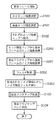
図1は、本発明の実施の形態に係る画像処理装置の主要部の構成を示すブロック図である。尚、本実施の形態では、画像データの処理の単位を、画像の輝度信号の8×8画素サイズ、及び色差信号の4×4画素サイズとし、これを対象ブロックと称す。 FIG. 1 is a block diagram showing a configuration of a main part of an image processing apparatus according to an embodiment of the present invention. In this embodiment, the unit of image data processing is set to an 8 × 8 pixel size of the luminance signal of the image and a 4 × 4 pixel size of the color difference signal, which are referred to as a target block.
図1において、水平エッジ強度測定器100は、画像の輝度信号の1ブロックを入力し、水平方向のエッジ強度を測定する。垂直エッジ強度測定器101は、その画像の輝度信号の1ブロックを入力し、垂直方向のエッジ強度を測定する。本実施の形態では、処理単位の対象ブロックの画素に対するエッジ強度をSobelフィルタの累積値で表す。
In FIG. 1, a horizontal edge
図8(A)(B)は、本実施の形態で用いるSobelフィルタのオペレータの一例を示す図である。図8(A)は、水平エッジ強度測定器100で使用される3×3の水平Sobelフィルタを示し、図8(B)は、垂直エッジ強度測定器101で使用される3×3の垂直Sobelフィルタの一例を示している。
8A and 8B are diagrams illustrating an example of the operator of the Sobel filter used in the present embodiment. 8A shows a 3 × 3 horizontal Sobel filter used in the horizontal edge
エッジ強度マップメモリ(エッジ強度記憶部)102は、水平及び垂直エッジ強度測定器100,101で測定した水平及び垂直方向のエッジ強度データを入力して、各ブロック単位に1フレーム分だけ格納する。尚、このエッジ強度マップメモリ102は2バンク構成であり、一方のメモリバンクに現フレームのエッジ強度データを格納しながら、他方のメモリバンクから、格納されている直前のフレームのエッジ強度データを読み出すことが可能である。このメモリバンクの切替は1フレーム処理毎に行う。除去フラグ算出器103は、エッジ強度マップメモリ102に格納された各ブロック毎のエッジ強度データから、ノイズ除去の対象ブロックかどうかを示すフラグ(特定情報)を算出する。除去フラグマップメモリ104は、この除去フラグ算出器103で算出された除去フラグを、各ブロック単位で1フレーム分だけ格納する。尚、この除去フラグマップメモリ104も2バンク構成であり、一方のメモリバンクに除去フラグを格納しながら他方のメモリバンクから、格納されている直前のフレームの除去フラグを読み出すことが可能である。このメモリバンクの切替は1フレーム処理毎に行う。
An edge strength map memory (edge strength storage unit) 102 inputs edge strength data in the horizontal and vertical directions measured by the horizontal and vertical edge
フィルタ制御器105は、現フレームの水平及び垂直エッジ強度データ、及び直前のフレームのエッジ強度データと、直前のフレームの除去フラグから、後述する2Dフィルタ106を適用するか否かを制御している。ここで、現フレームの水平及び垂直エッジ強度データはそれぞれ、水平エッジ強度測定器100と垂直エッジ強度測定器101により測定された結果である。また直前のフレームのエッジ強度データは、エッジ強度マップメモリ102から読み出され、また直前のフレームの除去フラグは除去フラグマップメモリ104から読み出される。
The
2Dフィルタ106は、フィルタ制御器105からの制御信号110により、対象とする色差信号のブロックを入力し、フレーム内の二次元(以降、2D)フィルタ処理を実行する。
The
尚、本実施の形態では、この2Dフィルタ106にεフィルタを用いる。
In the present embodiment, an ε filter is used as the
図9は、このεフィルタ処理を説明する図である。 FIG. 9 is a diagram for explaining the ε filter processing.
このフィルタ処理では、中心画素の画素値f(x,y)とその近傍画素の画素値f(x+i,y+j),(x,y=−M,...,0,1,...,M)の差分値を計算する。そして、その差分値の絶対値がεよりも大きい場合は、その近傍の画素の画素値を中心画素の画素値に置き換えて平滑化処理を行う。その結果、図9の数式で得られるg(x,y)では、エッジ成分を保護し、小振幅の高調波であるノイズを平滑化して抑制することができる。ここでMは、εフィルタの画素の範囲を規定する値で、通常は「1」或は「2」(この実施の形態では「1」とする)である。またε0は、フィルタ値の範囲(平滑化対象レベル)を規定する値で、保存したエッジのレベル差よりも小さい値とし、通常は「10」以下、本実施の形態では「5」とする。尚、このεフィルタ処理の詳細は下記文献1を参照されたい。(文献1.原島博ほか「ε−分離非線形ディジタルフィルタとその応用」電子情報通信学会、昭57−論146〔A−36〕、昭和57年4月)
セレクタ107は、フィルタ制御器105からの制御信号111により、2Dフィルタ106からの出力、及びフィルタ無しの信号(入力したブロックの色差信号)を選択する。
In this filtering process, the pixel value f (x, y) of the central pixel and the pixel values f (x + i, y + j), (x, y = −M,..., 0, 1, ..., M) is calculated. If the absolute value of the difference value is larger than ε, the pixel value of the neighboring pixel is replaced with the pixel value of the central pixel, and smoothing processing is performed. As a result, in g (x, y) obtained by the mathematical formula of FIG. 9, the edge component can be protected and noise that is a harmonic having a small amplitude can be smoothed and suppressed. Here, M is a value that defines the pixel range of the ε filter, and is normally “1” or “2” (in this embodiment, “1”). Also, ε0 is a value that defines the range of filter values (level to be smoothed), and is a value smaller than the stored edge level difference, and is usually “10” or less, and “5” in the present embodiment. For details of the ε filter processing, see
The
以上の構成を備える装置における動作を図2、図3,図5、図6のフローチャートを参照して説明する。尚、本実施の形態では、先頭フレームとそれ以外のフレームで処理を切り替えるものとする。 The operation of the apparatus having the above configuration will be described with reference to the flowcharts of FIGS. 2, 3, 5, and 6. In the present embodiment, processing is switched between the first frame and the other frames.
図2は、本実施の形態に係る画像処理装置における、入力した画像の先頭フレームに対する処理を説明するフローチャートである。 FIG. 2 is a flowchart for explaining processing for the first frame of the input image in the image processing apparatus according to the present embodiment.
図3は、本実施の形態に係る画像処理装置における、入力した画像の先頭フレーム以降のフレームに対する処理を説明するフローチャートである。 FIG. 3 is a flowchart for explaining processing for frames after the first frame of the input image in the image processing apparatus according to the present embodiment.
まず先頭フレームの処理を図2を参照して説明する。 First, processing of the first frame will be described with reference to FIG.
まずステップS100で、入力した輝度信号のブロック(ここでは8×8画素)に対して、水平エッジ強度測定器100で水平エッジの強度を測定する。これと並行してステップS101で、入力した輝度信号のブロックに対して垂直エッジ強度測定器101にて、垂直エッジの強度を測定する。そしてステップS102で、それぞれの測定値(エッジ強度データ)をエッジ強度マップメモリ102へ格納する。こうして先頭フレームに対する除去フラグマップを除去フラグマップメモリ104に格納した後、エッジ強度マップメモリ102のバンク切り替えを行って、ステップS102で格納したエッジ強度マップメモリ102からのデータを読み出し可能にする。
First, in step S100, the horizontal edge
次にステップS103に進み、エッジ強度マップメモリ102に格納されたエッジ強度データに基づき、除去フラグ算出器103にて除去フラグマップを作成する。この処理は図5のフローチャートを参照して詳しく説明する。次にステップS104で、除去フラグマップメモリ104のバンクを切り替える。これにより、次のフレームでは、エッジ強度マップメモリ102及び除去フラグマップメモリ104の格納済みのバンクからエッジ強度データや除去フラグマップを読み出す。そして、次のフレームに対する処理では、測定したエッジ強度データや、計算した除去フラグマップが、各対応するメモリの他方のバンクに格納されることになる。
In
以上の処理により、入力した画像の先頭フレームでは、エッジ強度マップメモリ102及び除去フラグマップメモリ104への格納処理のみを行い、ノイズ除去のためのフィルタ制御は行わない。
With the above processing, only the storage processing in the edge
次に先頭フレーム以降のフレームに対する処理について、図3を参照して説明する。このフレームでは、前述の図2の先頭フレームに対する処理(S100〜S104)に、ステップS200〜S203で示す処理が追加されたものとなる。従って、ここではこれら追加されたステップS200〜S203について説明する。 Next, processing for the first and subsequent frames will be described with reference to FIG. In this frame, the process shown in steps S200 to S203 is added to the process (S100 to S104) for the first frame in FIG. Therefore, here, these added steps S200 to S203 will be described.
ステップS102で、現フレームのエッジ強度をエッジ強度マップメモリ102へ格納した後、ステップS200で、エッジ強度マップメモリ102に格納された直前のフレームのブロック毎のエッジ強度データを読み出す。またステップS201で、除去フラグマップメモリ104に格納された直前のフレームのブロック毎の除去フラグマップ(ノイズ除去対象ブロック)を読み出す。次にステップS202に進み、これら直前のフレームのエッジ強度データと除去フラグマップから、2Dフィルタ106の制御信号110及びセレクタ107の制御信号111を生成する。そしてステップS203で、これら制御信号110,111によりノイズ除去フィルタ処理を実行する。次にステップS103で、エッジ強度マップメモリ102に記憶された現フレームのエッジ強度データに基づいて、現フレームに対する除去フラグマップを生成する。そしてこれ以降の処理は図2と同様であるため、その説明を省略する。
After the edge strength of the current frame is stored in the edge
図4(A)〜(C)は、本実施の形態に係るエッジ強度マップメモリ102及び除去フラグマップメモリ104のデータ構成を説明する図である。
4A to 4C are diagrams for explaining the data structures of the edge
図4(A)は、強度データ或は除去フラグを記憶する1フレーム分のメモリエリアを示し、400は、1ブロックに対応するデータエリアを示している。図4(B)は、エッジ強度マップメモリ102のデータエリア400に記憶されるデータ構成を示す。ここには水平エッジ強度測定器100で求められた水平エッジ強度データと、垂直エッジ強度測定器101で求められた垂直エッジ強度データとが対で記憶されている。図4(C)は、除去フラグマップメモリ104に記憶されるノイズ除去対象のブロックであるか否かを示すノイズ除去対象フラグと、後述する拡張したブロックのエッジ強度データと拡張元のブロックのエッジ強度データとの差分値とが記憶される。尚、この差分値は、後述する拡張したブロックでのみ格納される。
FIG. 4A shows a memory area for one frame for storing intensity data or a removal flag, and 400 shows a data area corresponding to one block. FIG. 4B shows a data structure stored in the
図5は、図2及び図3のステップS103の除去フラグマップの生成処理を説明するフローチャートである。 FIG. 5 is a flowchart for explaining the generation process of the removal flag map in step S103 of FIGS.
ステップS300で、エッジ強度マップメモリ102に格納された現フレームの水平及び垂直エッジ強度データを読み出して加算し、その現フレームの各ブロック毎のエッジ強度データを算出する。次にステップS301で、これら測定し格納した現フレームの各ブロックのエッジ強度データのうち、閾値EP1よりもエッジ強度が高い(エッジ強度データが大きい)ブロックを抽出する。そして、その抽出したブロックに対応するイズ除去対象フラグをオンにする。次にステップS302で、その抽出したブロックの周辺(隣接)8ブロックのエッジ強度を計算する。次にステップS303で、その周囲8ブロックに対し、閾値EP2(EP2<EP1)よりもエッジ強度が低くなる(エッジ強度データが小さい)場合に、ステップS301で求めたエッジ強度の高いブロックを含めた拡張ブロックと判定する。そしてステップS304で、この処理により得られた拡張ブロックに対するノイズ除去対象フラグをオンにし、それ以外のブロックに対してはノイズ除去対象フラグをオフにして除去フラグを除去フラグマップメモリ104へ格納する。また、その拡張ブロックに対しては、拡張したブロックのエッジ強度データと、拡張元のブロックのエッジ強度データとの差分値を格納する(図4(C)参照)。
In step S300, the horizontal and vertical edge strength data of the current frame stored in the edge
図6は、図3のフローチャートのステップS202のフィルタ制御処理(制御信号110,111の生成処理)を説明するフローチャートである。ここでの処理の対象は、前述したノイズ除去対象フラグがオンであるブロックである。 FIG. 6 is a flowchart for explaining the filter control process (the generation process of the control signals 110 and 111) in step S202 of the flowchart of FIG. The processing target here is a block in which the above-described noise removal target flag is on.
まずステップS300で、前述の図5のステップS300と同様に、エッジ強度マップメモリ102に格納された現フレームの水平、垂直エッジ強度データを加算して現フレームのエッジ強度データを算出する。次にステップS401で、エッジ強度マップメモリ102の別のメモリバンクに記憶されている直前フレームの水平、垂直エッジ強度データを読み出して加算し、直前フレームのエッジ強度データを算出する。次にステップS402に進み、ステップS300で算出した現フレームのエッジ強度データと、ステップS401で求めた直前フレームのエッジ強度データとの差分を求める。この結果、{(直前のフレームのエッジ強度データ)−(現フレームのエッジ強度データ)}の差分値の絶対値が閾値TH1以下かどうかを判定する。閾値TH1以下の場合は、そのブロックがノイズ除去対象ブロックであると判断してステップS403に進む。そうでない場合は、フィルタ処理の必要がないと判断してステップS405に進み、制御信号111によりセレクタ107が入力した画像のブロックをそのまま出力するように制御する。尚、この閾値TH1は、水平及び/或は垂直エッジが存在しているが、例えば細かい網目のようなブロックに対するフィルタリング処理を除外するための閾値である。
First, in step S300, as in step S300 of FIG. 5 described above, the horizontal and vertical edge strength data of the current frame stored in the edge
ノイズ除去対象ブロックに対するステップS403の処理では、フィルタの種類を選択するため、現フレームの垂直エッジ強度データから水平エッジ強度データを減算し、その差分値が閾値TH2以下かどうかを判定する。ここで閾値TH2(TH2<TH1)以下の場合は、水平及び垂直方向のエッジ強度差が少ないためステップS404に進み、2Dフィルタ106を実行するための制御信号110を生成する。その他の場合は、垂直方向のエッジが強いためステップS405に進み、フィルタ処理をパスしてセレクタ107が、入力したブロックの画像信号を選択するように制御信号111を生成する。この閾値TH2は、インターレースに特有の水平方向のノイズに対するフィルタリング処理を除外するための値である。
In the process of step S403 for the noise removal target block, in order to select the filter type, the horizontal edge intensity data is subtracted from the vertical edge intensity data of the current frame, and it is determined whether or not the difference value is equal to or less than the threshold value TH2. If the threshold value TH2 (TH2 <TH1) is not greater than the threshold value TH2, the process proceeds to step S404 because the edge strength difference between the horizontal and vertical directions is small, and the
図7は、具体的な直前フレームのエッジ領域の拡張例と、現フレームのノイズ除去対象ブロックを決定するまでの例を説明する図である。尚、図7において、各桝目は、前述のブロックに対応している。 FIG. 7 is a diagram for explaining a specific example of extending the edge region of the immediately preceding frame and an example of determining the noise removal target block of the current frame. In FIG. 7, each cell corresponds to the block described above.
まず直前のフレーム700では、閾値EP1よりもエッジ強度データが大きいブロック710を選定する(S301)。そしてエッジ強度データが極度に小さい閾値EP2以下のブロック711へ、そのブロック710の領域を拡張し(S303)、以降の処理のノイズ除去対象ブロックとする(S304)。図7の例では、直前フレーム700の太線で示すブロック712が、これら拡張された領域である。
First, in the immediately preceding frame 700, a
次に、直前のフレーム700のエッジ強度データと現フレーム701のエッジ強度データとの差分値を求める。そして、その差分値が閾値TH1(S402)以下、または現フレーム701のエッジ強度データが閾値EP1以上となった場合(S301)はノイズ除去対象のブロック領域とする。その他の場合は、ノイズ除去対象ブロックから除外する。図7の現フレーム701において、714は現フレーム701のエッジ強度データが閾値EP1以下でノイズ除去対象ブロックから除外されたブロックを示している。また715は、現フレーム701のエッジ強度データが閾値EP1以上になって拡張ブロックからノイズ除去対象領域に変更した領域を示している。
Next, a difference value between the edge strength data of the immediately previous frame 700 and the edge strength data of the
図10は、本発明の実施の形態に係る画像処理装置を実現するコンピュータ機器のハードウェア構成を示すブロック図である。 FIG. 10 is a block diagram showing a hardware configuration of a computer device that realizes the image processing apparatus according to the embodiment of the present invention.
CPU1000は、このコンピュータ機器(画像処理装置)の全体の制御、及び種々の処理を行う。メモリ1001は、このコンピュータ機器の制御に必要なオペレーティングシステム(OS)、ソフトウエア(前述のフローチャートに示すプログラム)やデータを記憶するとともに、演算等の処理に必要な記憶領域を提供している。また、このメモリ1001は、CPU1000が各種の処理を行う際のワークエリアとしても用いられる。システムバス1002は、CPU1000と各部とを接続し、データや制御信号をやりとりする。記憶部1003は、前述のフローチャートに示すプログラム等の各種のソフトウエアを蓄積する大容量のハードディスク等の記憶部である。記憶部1004は動画像データを蓄積する記憶部(ハードディスク、MO,CD,DVD等)である。モニタ(表示部)1005は、画像やコンピュータからのシステムメッセージなどを表示する。
The
通信インターフェース(I/F)1007は、通信回路1008に符号化データを送信する通信インターフェースであり、装置外部のLAN、公衆回線、無線回線、放送電波等と接続されている。端末1006は、このコンピュータ機器を起動したり、各種条件を設定したりする。またメモリ1001には、このコンピュータ機器全体を制御し、各種ソフトウエアを動作させるためのOSや動作させるソフトウエアを格納し、画像データを読み込むエリア、各種演算のパラメータ等を格納しておくワーキングエリアが存在する。
A communication interface (I / F) 1007 is a communication interface that transmits encoded data to the
以上の構成において、処理に先立ち、端末1006から記憶部1004に蓄積されている動画像データから符号化する動画像データを選択して、このコンピュータ機器の起動が指示される。これにより記憶部1003に格納されているプログラムがシステムバス1002を介してメモリ1001のプログラム格納エリアに展開され、この展開されたプログラムが起動される。
In the above configuration, prior to processing, moving image data to be encoded is selected from the moving image data stored in the
そして、CPU1000による記憶部1004に格納されている動画像データの符号化処理が開始されると、前述の図2,図3、図5、図6に示すフローチャートに従ったプログラムコードが実行されることになる。
When the encoding process of the moving image data stored in the
以上説明したように本実施の形態に係るコンピュータ機器は、本実施の形態に係るノイズ除去を実現する装置として機能する。 As described above, the computer apparatus according to the present embodiment functions as a device that implements noise removal according to the present embodiment.
[実施の形態のその他の構成]
本実施の形態では、色信号の処理対象ブロックのサイズを4×4画素としたが、8×4,4×8,8×8などのサイズでもかまわない。
[Other configurations of the embodiment]
In this embodiment, the size of the color signal processing target block is 4 × 4 pixels, but it may be 8 × 4, 4 × 8, 8 × 8, or the like.
またエッジ強度測定器100,101の処理では図8(A)(B)に示すSobelフィルタを用いたが、そのほかの微分フィルタでもかまわない。
In the processing of the edge
また2Dフィルタ106は、図9(A)(B)に示すオペレータを用いたがその他のものでもかまわない。
The
更に、フレームメモリはフレーム画像を格納するものとしたが、フィールド画像を格納するフィールドメモリでもかまわない。 Further, although the frame memory stores frame images, it may be a field memory that stores field images.
除去フラグ算出器103における閾値EP1,EP2は固定ではなく、フレーム毎に可変に設定してもかまわない。
The threshold values EP1 and EP2 in the
2Dフィルタにεフィルタを用いたが、そのほかの簡便なローパスフィルタでもかまわない。 Although the ε filter is used for the 2D filter, other simple low-pass filters may be used.
以上説明したように本実施の形態によれば、インターレース信号を含む動画像符号化装置及びその方法において、画像データに含まれるモスキートノイズのような符号化ノイズの発生部分を的確に検出できる。またインターレース信号の状態を維持しつつ、色差信号のノイズ除去処理を施すことができる。 As described above, according to the present embodiment, it is possible to accurately detect a portion where coding noise such as mosquito noise included in image data is generated in the moving image coding apparatus and method including interlace signals. Further, it is possible to perform noise removal processing of the color difference signal while maintaining the state of the interlace signal.
以上説明したように本実施の形態によれば、画像データに含まれるモスキートノイズのような符号化ノイズの発生部分を的確に検出することが可能になる。また本来の画像が持つテクスチャを保持しつつ、ノイズ発生部分に対してのみノイズ除去処理を施すことができる。 As described above, according to the present embodiment, it is possible to accurately detect a portion where coding noise such as mosquito noise included in image data is generated. In addition, it is possible to perform noise removal processing only on the noise generation portion while maintaining the texture of the original image.
(他の実施形態)
以上、本発明の実施形態について詳述したが、本発明は、複数の機器から構成されるシステムに適用しても良いし、また一つの機器からなる装置に適用しても良い。
(Other embodiments)
Although the embodiments of the present invention have been described in detail above, the present invention may be applied to a system constituted by a plurality of devices or may be applied to an apparatus constituted by one device.
なお、本発明は、前述した実施形態の機能を実現するソフトウェアのプログラムを、システム或いは装置に直接或いは遠隔から供給し、そのシステム或いは装置のコンピュータが該供給されたプログラムを読み出して実行することによっても達成され得る。その場合、プログラムの機能を有していれば、形態は、プログラムである必要はない。 In the present invention, a software program that implements the functions of the above-described embodiments is supplied directly or remotely to a system or apparatus, and the computer of the system or apparatus reads and executes the supplied program. Can also be achieved. In that case, as long as it has the function of a program, the form does not need to be a program.
従って、本発明の機能処理をコンピュータで実現するために、該コンピュータにインストールされるプログラムコード自体も本発明を実現するものである。つまり、本発明のクレームでは、本発明の機能処理を実現するためのコンピュータプログラム自体も含まれる。その場合、プログラムの機能を有していれば、オブジェクトコード、インタプリタにより実行されるプログラム、OSに供給するスクリプトデータ等、プログラムの形態を問わない。 Accordingly, since the functions of the present invention are implemented by computer, the program code installed in the computer also implements the present invention. That is, the claims of the present invention include the computer program itself for realizing the functional processing of the present invention. In this case, the program may be in any form as long as it has a program function, such as an object code, a program executed by an interpreter, or script data supplied to the OS.
プログラムを供給するための記録媒体としては、様々なものが使用できる。例えば、フロッピー(登録商標)ディスク、ハードディスク、光ディスク、光磁気ディスク、MO、CD−ROM、CD−R、CD−RW、磁気テープ、不揮発性のメモリカード、ROM、DVD(DVD−ROM,DVD−R)などである。 Various recording media for supplying the program can be used. For example, floppy (registered trademark) disk, hard disk, optical disk, magneto-optical disk, MO, CD-ROM, CD-R, CD-RW, magnetic tape, nonvolatile memory card, ROM, DVD (DVD-ROM, DVD- R).
その他、プログラムの供給方法としては、クライアントコンピュータのブラウザを用いてインターネットのホームページに接続し、該ホームページからハードディスク等の記録媒体にダウンロードすることによっても供給できる。その場合、ダウンロードされるのは、本発明のコンピュータプログラムそのもの、もしくは圧縮され自動インストール機能を含むファイルであってもよい。また、本発明のプログラムを構成するプログラムコードを複数のファイルに分割し、それぞれのファイルを異なるホームページからダウンロードすることによっても実現可能である。つまり、本発明の機能処理をコンピュータで実現するためのプログラムファイルを複数のユーザに対してダウンロードさせるWWWサーバも、本発明のクレームに含まれるものである。 As another program supply method, the program can be supplied by connecting to a home page on the Internet using a browser of a client computer and downloading the program from the home page to a recording medium such as a hard disk. In this case, the computer program itself of the present invention or a compressed file including an automatic installation function may be downloaded. It can also be realized by dividing the program code constituting the program of the present invention into a plurality of files and downloading each file from a different homepage. That is, a WWW server that allows a plurality of users to download a program file for realizing the functional processing of the present invention on a computer is also included in the claims of the present invention.
また、本発明のプログラムを暗号化してCD−ROM等の記憶媒体に格納してユーザに配布する形態としても良い。その場合、所定の条件をクリアしたユーザに対し、インターネットを介してホームページから暗号化を解く鍵情報をダウンロードさせ、その鍵情報を使用することにより暗号化されたプログラムが実行可能な形式でコンピュータにインストールされるようにする。 Further, the program of the present invention may be encrypted, stored in a storage medium such as a CD-ROM, and distributed to users. In that case, a user who has cleared a predetermined condition is allowed to download key information to be decrypted from a homepage via the Internet, and using the key information, the encrypted program can be executed on a computer in a format that can be executed. To be installed.
また、コンピュータが、読み出したプログラムを実行することによって、前述した実施形態の機能が実現される形態以外の形態でも実現可能である。例えば、そのプログラムの指示に基づき、コンピュータ上で稼動しているOSなどが、実際の処理の一部または全部を行ない、その処理によっても前述した実施形態の機能が実現され得る。 Further, the present invention can be realized in a form other than the form in which the functions of the above-described embodiments are realized by the computer executing the read program. For example, based on the instructions of the program, an OS or the like running on the computer performs part or all of the actual processing, and the functions of the above-described embodiments can also be realized by the processing.
更に、記録媒体から読み出されたプログラムが、コンピュータに挿入された機能拡張ボードやコンピュータに接続された機能拡張ユニットに備わるメモリに書き込まれるようにしてもよい。この場合、その後で、そのプログラムの指示に基づき、その機能拡張ボードや機能拡張ユニットに備わるCPUなどが実際の処理の一部または全部を行ない、その処理によって前述した実施形態の機能が実現される。 Furthermore, the program read from the recording medium may be written in a memory provided in a function expansion board inserted into the computer or a function expansion unit connected to the computer. In this case, thereafter, based on the instructions of the program, the CPU or the like provided in the function expansion board or function expansion unit performs part or all of the actual processing, and the functions of the above-described embodiments are realized by the processing. .
100 水平エッジ強度測定器
101 垂直エッジ強度測定器
102 エッジ強度マップメモリ
103 除去フラグ算出器
104 除去フラグマップメモリ
105 フィルタ制御器
106 2Dフィルタ
107 セレクタ
DESCRIPTION OF
Claims (10)
前記水平及び垂直エッジ強度データを少なくとも1フレーム分記憶するエッジ強度記憶手段と、
前記エッジ強度記憶手段に記憶された各ブロック単位の水平及び垂直エッジ強度データから各ブロックのエッジ強度データを算出し、当該ブロックのエッジ強度データの大きさから、フィルタリング処理を行う対象ブロックを特定する特定情報を算出する算出手段と、
前記算出手段により算出された前記特定情報を少なくとも1フレーム分記憶する記憶手段と、
前記画像の前記輝度信号の対象ブロックに対応する色差信号の対象ブロックにフィルタリング処理を行うフィルタ手段と、
前記記憶手段に記憶した前記特定情報により特定される前記フィルタリング処理を行う対象ブロックに対して、前記エッジ強度測定手段により算出した現フレームに対する水平及び垂直エッジ強度データから算出した前記対象ブロックに対応するブロックのエッジ強度データと、前記エッジ強度記憶手段に記憶された前記現フレームの直前フレームの前記対象ブロックに対応するブロックの水平及び垂直エッジ強度データから算出したエッジ強度データとの差分値と、前記現フレームの対象ブロックの垂直エッジ強度データと水平エッジ強度データとの差分値とから、前記現フレームの対応する色差信号の対象ブロックに前記フィルタ手段によるフィルタリング処理を行って出力するか否かを制御するフィルタ制御手段と、
を有することを特徴とする画像処理装置。 An edge intensity measuring means for calculating the horizontal and vertical edge intensity data by measuring the intensity of the horizontal and vertical edges with respect to each block definitive the luminance signal of the image,
An edge intensity storing means for one frame stored even the horizontal and vertical edge intensity data small without
The calculated edge intensity data of each block from the horizontal and vertical edge intensity data of each block stored in the edge intensity storage unit, the edge intensity data of the block from the size, the pair Zobu lock for performing a filtering process A calculation means for calculating specific information to be identified;
Storage means for storing the specific information calculated by the calculation means for at least one frame;
Filter means for performing a filtering process on the target block of the color difference signal corresponding to the target block of the luminance signal of the image;
Relative pair Zobu lock to perform the filtering process specified by the specifying information stored in the storage means, the target block is calculated from the horizontal and vertical edge intensity data for the current frame calculated by the edge intensity measuring means an edge intensity of the corresponding block data, and the difference value of the edge intensity data calculated from the horizontal and vertical edge intensity data block corresponding to the current block of the immediately preceding frame of the current frame stored in the edge intensity storage unit , whether the from the difference value between the vertical edge intensity data and the horizontal edge intensity data of the target block in the current frame corresponds to performing a filtering process by the filter means to the target block of the color difference signal output of the previous Kigen frame Filter control means for controlling
An image processing apparatus comprising:
前記エッジ強度記憶手段に記憶された前記水平及び垂直エッジ強度データを各ブロックごとに加算して、前記直前フレームの各ブロックのエッジ強度データを算出する手段と、
前記エッジ強度測定手段により算出された前記現フレームの水平及び垂直エッジ強度データを、対応する各ブロックごとに加算して、前記現フレームの各ブロックのエッジ強度データを算出する手段とを有し、
前記直前フレームと前記現フレームの各対応するブロックのエッジ強度データの差分値と、前記現フレームの対象ブロックの垂直エッジ強度データと水平エッジ強度データとの差分値とから、前記フィルタ手段によりフィルタリング処理した色差信号の対象ブロックを採用するか否かを決定することを特徴とする請求項1に記載の画像処理装置。 The filter control means includes
Said the horizontal and vertical Chokue Tsu di intensity data stored in the edge intensity storage unit is added to each block, means for calculating the edge intensity data of each block of the previous frame,
The horizontal and vertical Chokue Tsu di intensity data of the current frame calculated by the edge intensity measuring means, is added to each corresponding blocks, and means for calculating the edge intensity data of each block of the current frame Have
From said previous frame the difference value of the edge intensity data of each corresponding block of the current frame, the difference value between the vertical edge intensity data and the horizontal edge intensity data of the target block in the current frame, the filtering processing by the filter means The image processing apparatus according to claim 1, wherein it is determined whether or not to use the target block of the color difference signal.
前記エッジ強度測定工程で算出した前記水平及び垂直エッジ強度データを少なくとも1フレーム分第1メモリに記憶するエッジ強度記憶工程と、
前記第1メモリに記憶された各ブロック単位の水平及び垂直エッジ強度データから各ブロックのエッジ強度データを算出し、当該ブロックのエッジ強度データの大きさから、フィルタリング処理を行う対象ブロックを特定する特定情報を算出する算出工程と、
前記算出工程で算出された前記特定情報を少なくとも1フレーム分第2メモリに記憶する記憶工程と、
前記画像の前記輝度信号の対象ブロックに対応する色差信号の対象ブロックにフィルタリング処理を行うフィルタ工程と、
前記第2メモリに記憶した前記特定情報により特定される前記フィルタリング処理を行う対象ブロックに対して、前記エッジ強度測定工程で算出した現フレームに対する水平及び垂直エッジ強度データから算出した前記対象ブロックに対応するブロックのエッジ強度データと、前記第1メモリに記憶された前記現フレームの直前フレームの前記対象ブロックに対応するブロックの水平及び垂直エッジ強度データから算出したエッジ強度データとの差分値と、前記現フレームの対象ブロックの垂直エッジ強度データと水平エッジ強度データとの差分値とから、前記現フレームの対応する色差信号の対象ブロックに前記フィルタ工程によるフィルタリング処理を行って出力するか否かを制御するフィルタ制御工程と、
を有することを特徴とする画像処理方法。 An edge intensity measuring step of calculating the horizontal and vertical edge intensity data by measuring the intensity of the horizontal and vertical edges with respect to each block definitive the luminance signal of the image,
An edge intensity storage step of storing in one frame the first memory even the horizontal and vertical edge intensity data calculated by the edge intensity measuring step small without
The first calculates the edge intensity data of each block from the horizontal and vertical edge intensity data of each block stored in the memory, the size of the edge intensity data of the block, identifying pairs Zobu lock for performing a filtering process A calculation step of calculating specific information to be performed;
A storage step of storing the specific information calculated in the calculation step in a second memory for at least one frame;
A filtering step for performing a filtering process on the target block of the color difference signal corresponding to the target block of the luminance signal of the image;
Relative pair Zobu lock to perform the filtering process specified by the specifying information stored in the second memory, the target block is calculated from the horizontal and vertical edge intensity data for the current frame calculated by the edge intensity measuring step an edge intensity data of the corresponding block to a difference value between the edge intensity data calculated from the horizontal and vertical edge intensity data of the block corresponding to the target block of the immediately preceding frame of the said current frame stored in the first memory , whether the from the difference value between the vertical edge intensity data and the horizontal edge intensity data of the target block in the current frame, a corresponding to the target block of the color difference signals by performing a filtering process by the filter process the output of the previous Kigen frame A filter control process for controlling
An image processing method comprising:
前記第1メモリに記憶された前記水平及び垂直エッジ強度データを各ブロックごとに加算して、前記直前フレームの各ブロックのエッジ強度データを算出する工程と、
前記エッジ強度測定工程で算出された前記現フレームの水平及び垂直エッジ強度データを、対応する各ブロックごとに加算して、前記現フレームの各ブロックのエッジ強度データを算出する工程とを有し、
前記直前フレームと前記現フレームの各対応するブロックのエッジ強度データの差分値と、前記現フレームの対象ブロックの垂直エッジ強度データと水平エッジ強度データとの差分値とから、前記フィルタ工程によりフィルタリング処理した色差信号の対象ブロックを採用するか否かを決定することを特徴とする請求項6に記載の画像処理方法。 The filter control step includes
Said first said horizontal and vertical Chokue Tsu di intensity data stored in the memory is added to each block, a step of calculating an edge intensity data of each block of the previous frame,
The horizontal and vertical Chokue Tsu di intensity data of the current frame calculated by the edge intensity measuring step, is added to each corresponding blocks, and a step of calculating the edge intensity data of each block of the current frame Have
From said previous frame the difference value of the edge intensity data of each corresponding block of the current frame, the difference value between the vertical edge intensity data and the horizontal edge intensity data of the target block in the current frame, the filtering process by the filter process 7. The image processing method according to claim 6, wherein it is determined whether or not to adopt the target block of the color difference signal.
Priority Applications (3)
| Application Number | Priority Date | Filing Date | Title |
|---|---|---|---|
| JP2007014200A JP4931215B2 (en) | 2007-01-24 | 2007-01-24 | Image processing apparatus and method |
| US11/972,442 US8189946B2 (en) | 2007-01-24 | 2008-01-10 | Image processing apparatus and method thereof for detecting and removing noise in decoded images |
| CN2008100042649A CN101232573B (en) | 2007-01-24 | 2008-01-24 | Image processing apparatus and method thereof |
Applications Claiming Priority (1)
| Application Number | Priority Date | Filing Date | Title |
|---|---|---|---|
| JP2007014200A JP4931215B2 (en) | 2007-01-24 | 2007-01-24 | Image processing apparatus and method |
Publications (3)
| Publication Number | Publication Date |
|---|---|
| JP2008182478A JP2008182478A (en) | 2008-08-07 |
| JP2008182478A5 JP2008182478A5 (en) | 2010-04-15 |
| JP4931215B2 true JP4931215B2 (en) | 2012-05-16 |
Family
ID=39726043
Family Applications (1)
| Application Number | Title | Priority Date | Filing Date |
|---|---|---|---|
| JP2007014200A Expired - Fee Related JP4931215B2 (en) | 2007-01-24 | 2007-01-24 | Image processing apparatus and method |
Country Status (1)
| Country | Link |
|---|---|
| JP (1) | JP4931215B2 (en) |
Families Citing this family (6)
| Publication number | Priority date | Publication date | Assignee | Title |
|---|---|---|---|---|
| KR20100050005A (en) * | 2008-11-04 | 2010-05-13 | 한국전자통신연구원 | Anisotropic diffusion method and apparatus based on directions of edge |
| JP5143033B2 (en) * | 2009-01-28 | 2013-02-13 | キヤノン株式会社 | Image processing apparatus and method |
| US8306355B2 (en) * | 2009-07-13 | 2012-11-06 | Sharp Laboratories Of America, Inc. | Methods and systems for reducing compression artifacts |
| US8363974B2 (en) * | 2009-07-21 | 2013-01-29 | Qualcomm Incorporated | Block artifact reducer |
| JP5233897B2 (en) * | 2009-07-31 | 2013-07-10 | ソニー株式会社 | Image processing apparatus and method |
| KR101172856B1 (en) | 2011-01-03 | 2012-08-09 | 엠텍비젼 주식회사 | Image processing device and edge arrange method |
Family Cites Families (3)
| Publication number | Priority date | Publication date | Assignee | Title |
|---|---|---|---|---|
| JP3081412B2 (en) * | 1993-06-01 | 2000-08-28 | シャープ株式会社 | Image signal decoder |
| JPH10191326A (en) * | 1996-11-08 | 1998-07-21 | Sony Corp | Image processor and method therefor |
| JP2006270220A (en) * | 2005-03-22 | 2006-10-05 | Victor Co Of Japan Ltd | Video signal processing apparatus |
-
2007
- 2007-01-24 JP JP2007014200A patent/JP4931215B2/en not_active Expired - Fee Related
Also Published As
| Publication number | Publication date |
|---|---|
| JP2008182478A (en) | 2008-08-07 |
Similar Documents
| Publication | Publication Date | Title |
|---|---|---|
| US8189946B2 (en) | Image processing apparatus and method thereof for detecting and removing noise in decoded images | |
| JP4533081B2 (en) | Image encoding apparatus and method | |
| US8326064B2 (en) | Image re-encoding method to decode image data which is orthogonally transformed per first block and encoded by a first encoding method | |
| JP4931214B2 (en) | Image processing apparatus and method | |
| TWI521949B (en) | Image predictive coding apparatus, method and program, image predictive decoding apparatus, method and program, and coding decoding system and method | |
| EP1662802A1 (en) | Moving picture encoding method and moving picture decoding method | |
| JP4931215B2 (en) | Image processing apparatus and method | |
| KR20090100402A (en) | Image compression and decompression | |
| JP2008042565A (en) | Motion picture decoding device, and its method | |
| JP2001218210A (en) | Noise detection method, noise detector, image data processing unit, and recording medium | |
| JP4939273B2 (en) | Image coding apparatus and image coding method | |
| JP5055078B2 (en) | Image processing apparatus and method | |
| JP2006067302A (en) | Apparatus, method, and program for image encoding | |
| US6781637B2 (en) | Image change detecting apparatus and image change detecting method, image encoding apparatus and information recording medium with image change detecting program recorded readable by computer | |
| TWI782853B (en) | Image encoding device, image encoding method, image decoding device, image decoding method | |
| JP4449430B2 (en) | Image processing apparatus, image processing method, program, and recording medium | |
| EP1765015A1 (en) | Image encoding method, and image decoding method | |
| JP5143033B2 (en) | Image processing apparatus and method | |
| JP3715273B2 (en) | Image data smoothing processing apparatus, smoothing processing method, and smoothing processing program | |
| JP5180911B2 (en) | Noise removal control device and noise removal control method | |
| JP4196929B2 (en) | Noise detection apparatus and noise detection program | |
| JP2001094996A (en) | Block distortion reduction method and block distortion reduction device | |
| JP2009021786A (en) | Image encoding device and method | |
| JP2007300557A (en) | Image encoding device and image encoding method | |
| JP2010010768A (en) | Image encoding apparatus and image encoding method |
Legal Events
| Date | Code | Title | Description |
|---|---|---|---|
| A621 | Written request for application examination |
Free format text: JAPANESE INTERMEDIATE CODE: A621 Effective date: 20091216 |
|
| A521 | Request for written amendment filed |
Free format text: JAPANESE INTERMEDIATE CODE: A523 Effective date: 20100225 |
|
| A977 | Report on retrieval |
Free format text: JAPANESE INTERMEDIATE CODE: A971007 Effective date: 20120126 |
|
| TRDD | Decision of grant or rejection written | ||
| A01 | Written decision to grant a patent or to grant a registration (utility model) |
Free format text: JAPANESE INTERMEDIATE CODE: A01 Effective date: 20120210 |
|
| A01 | Written decision to grant a patent or to grant a registration (utility model) |
Free format text: JAPANESE INTERMEDIATE CODE: A01 |
|
| A61 | First payment of annual fees (during grant procedure) |
Free format text: JAPANESE INTERMEDIATE CODE: A61 Effective date: 20120213 |
|
| R151 | Written notification of patent or utility model registration |
Ref document number: 4931215 Country of ref document: JP Free format text: JAPANESE INTERMEDIATE CODE: R151 |
|
| FPAY | Renewal fee payment (event date is renewal date of database) |
Free format text: PAYMENT UNTIL: 20150224 Year of fee payment: 3 |
|
| LAPS | Cancellation because of no payment of annual fees |