JP4930552B2 - Recording sheet conveying apparatus and image forming apparatus - Google Patents
Recording sheet conveying apparatus and image forming apparatus Download PDFInfo
- Publication number
- JP4930552B2 JP4930552B2 JP2009153426A JP2009153426A JP4930552B2 JP 4930552 B2 JP4930552 B2 JP 4930552B2 JP 2009153426 A JP2009153426 A JP 2009153426A JP 2009153426 A JP2009153426 A JP 2009153426A JP 4930552 B2 JP4930552 B2 JP 4930552B2
- Authority
- JP
- Japan
- Prior art keywords
- light
- recording sheet
- paper
- light shielding
- shielding portion
- Prior art date
- Legal status (The legal status is an assumption and is not a legal conclusion. Google has not performed a legal analysis and makes no representation as to the accuracy of the status listed.)
- Expired - Fee Related
Links
Images


Landscapes
- Paper Feeding For Electrophotography (AREA)
- Controlling Sheets Or Webs (AREA)
Description
本発明は、記録シートの通過を検知する光センサを備えた記録シート搬送装置および画像形成装置に関する。 The present invention relates to a recording sheet conveying apparatus and an image forming apparatus provided with an optical sensor that detects passage of a recording sheet.
従来、発光素子から出射した光を受光素子で受光する光センサと、光センサの光の光路を遮蔽する位置と光路から外れた位置とに揺動可能な長尺状の揺動部材とを備えた記録シート搬送装置が知られている(特許文献1参照)。具体的に、この技術では、搬送される用紙(記録シート)で揺動部材の一端側が押されて、揺動部材の他端が光路から外れることで、用紙が通過したことが検知されている。 Conventionally, an optical sensor that receives light emitted from a light emitting element by a light receiving element, and a long swinging member that can swing to a position that shields the optical path of the light of the optical sensor and a position that deviates from the optical path are provided. A recording sheet conveying apparatus is known (see Patent Document 1). Specifically, in this technique, it is detected that the sheet has passed by pressing one end of the swing member with the transported sheet (recording sheet) and removing the other end of the swing member from the optical path. .
ところで、記録シート搬送装置内においては、用紙を複数のローラやガイドで案内しながら搬送するので、用紙の搬送中に紙粉が舞うことがある。そして、このように装置内に舞った紙粉が光センサ(発光素子・受光素子)に付着すると、検知を正常に行うことができなくなるといった問題があった。特に、従来技術では、用紙が揺動部材を通過した際に、揺動部材の他端が光路(発光素子と受光素子との間)から外れるので、外れることにより形成される空間内に紙粉が入って発光素子等に付着するおそれがあった。 By the way, in the recording sheet conveying apparatus, the paper is conveyed while being guided by a plurality of rollers and guides, so that paper dust may fly during the conveyance of the paper. And when the paper dust which flew in the apparatus in this way adheres to an optical sensor (light emitting element / light receiving element), there was a problem that detection could not be performed normally. In particular, in the prior art, when the paper passes through the swing member, the other end of the swing member is removed from the optical path (between the light emitting element and the light receiving element). May enter and adhere to the light emitting element or the like.
そこで、本発明は、光センサへの紙粉(シート粉)の付着を抑制することができる記録シート搬送装置および画像形成装置を提供することを目的とする。 SUMMARY An advantage of some aspects of the invention is that it provides a recording sheet conveying apparatus and an image forming apparatus capable of suppressing adhesion of paper powder (sheet powder) to an optical sensor.
前記課題を解決する本発明は、発光素子から出射した光を受光素子で受光する光センサと、記録シートの通過に連動して移動することで、前記受光素子での光の受光量を変化させる遮光部と、を備えた記録シート搬送装置であって、前記遮光部の移動方向で前記遮光部と対向し、前記遮光部と一体的に移動する対向部を備え、前記遮光部と前記対向部が、前記記録シートから発生するシート粉と同極性となる材料で形成され、前記受光量が最も大きくなる位置に前記遮光部が位置するときに、前記遮光部と前記対向部が、前記光の光軸方向から見て前記光を挟んで対向するとともに、前記発光素子および前記受光素子に近接するように構成されていることを特徴とする。 The present invention that solves the above-described problems changes the amount of light received by the light receiving element by moving in conjunction with the optical sensor that receives the light emitted from the light emitting element by the light receiving element and the passage of the recording sheet. A recording sheet conveying apparatus comprising: a light-shielding unit, wherein the light-shielding unit includes a facing unit that faces the light-shielding unit in a moving direction of the light-shielding unit and moves integrally with the light-shielding unit. Is formed of a material having the same polarity as the sheet powder generated from the recording sheet, and when the light shielding portion is located at a position where the amount of received light is the largest, the light shielding portion and the facing portion are The light-emitting element and the light-receiving element are configured to face each other with the light interposed therebetween as viewed from the optical axis direction.
本発明によれば、遮光部が、受光量が最も小さくなる位置(例えば、光を完全に遮る位置)に位置する際には、発光素子と受光素子の間に位置する遮光部でシート粉を反発させることができるので、発光素子と受光素子との間からシート粉が入って発光素子等に付着するのを抑制できる。また、遮光部が、受光量が最も大きくなる位置(例えば、光の光路から完全に外れる位置)に位置する際には、遮光部と対向部とが光を挟んで対向する、すなわち、発光素子と受光素子との間を挟んで対向する。これにより、遮光部と対向部によって発光素子と受光素子との間に入ろうとするシート粉を反発させることができるので、シート粉が発光素子等に付着するのを抑制できる。 According to the present invention, when the light shielding portion is located at a position where the amount of received light is the smallest (for example, a position where light is completely blocked), the sheet powder is applied to the light shielding portion located between the light emitting element and the light receiving element. Since it can be repelled, it can suppress that sheet powder enters between the light emitting element and the light receiving element and adheres to the light emitting element or the like. Further, when the light shielding part is located at a position where the amount of received light is the largest (for example, a position completely deviated from the optical path of the light), the light shielding part and the opposing part face each other with light interposed therebetween, that is, the light emitting element. And the light receiving element. Thereby, since the sheet powder which tries to enter between a light emitting element and a light receiving element can be repelled by a light shielding part and an opposing part, it can suppress that sheet powder adheres to a light emitting element etc.
本発明によれば、遮光部の位置に関わらず、シート粉と同極性となる材料で形成される遮光部単体もしくは遮光部および対向部の両方で、発光素子と受光素子との間に入ろうとするシート粉を撥ね返すことができるので、光センサへのシート粉の付着を抑制できる。 According to the present invention, regardless of the position of the light shielding part, the light shielding part alone or both of the light shielding part and the opposing part, which is formed of a material having the same polarity as the sheet powder, is intended to enter between the light emitting element and the light receiving element. Since the sheet powder to be repelled can be repelled, adhesion of the sheet powder to the optical sensor can be suppressed.
次に、本発明の一実施形態に係る画像形成装置の一例としてのレーザプリンタ1について、適宜図面を参照しながら詳細に説明する。 Next, a laser printer 1 as an example of an image forming apparatus according to an embodiment of the present invention will be described in detail with reference to the drawings as appropriate.
図1に示すように、レーザプリンタ1は、電子写真方式の画像形成装置であり、主に、記録シートの一例としての用紙Pを装置本体2内に給紙するためのフィーダ部3と、用紙Pに画像を形成するための画像形成部4と、用紙Pの通過を検知する用紙検知センサ8とを備えている。なお、以下の説明では、レーザプリンタ1の全体構造を簡単に説明した後で、用紙検知センサ8について詳述することとする。
As shown in FIG. 1, a laser printer 1 is an electrophotographic image forming apparatus, and mainly includes a feeder unit 3 for feeding a sheet P as an example of a recording sheet into the apparatus
フィーダ部3は、装置本体2内の底部に着脱可能に装着される給紙トレイ31と、用紙Pの搬送を行う用紙搬送機構32を主に備えている。そして、フィーダ部3では、給紙トレイ31内の用紙Pが、用紙搬送機構32によって画像形成部4に一枚ずつ搬送される。
The feeder unit 3 mainly includes a
画像形成部4は、スキャナユニット5、プロセスカートリッジ6、定着器7などを備えている。
The image forming unit 4 includes a
スキャナユニット5は、装置本体2内の上部に設けられ、図示しないレーザ発光部、ポリゴンミラー、レンズおよび反射鏡などを備えている。このスキャナユニット5では、レーザビームを、感光ドラム65の表面上に高速走査にて照射する。
The
プロセスカートリッジ6は、装置本体2の手前側に設けられたフロントカバー2Aを開放することで、装置本体2に着脱可能となっている。プロセスカートリッジ6内には、現像ローラ61、層厚規制ブレード62、供給ローラ63、トナー収容室64、アジテータ64A、感光ドラム65、帯電器66および転写ローラ67が設けられている。
The process cartridge 6 can be attached to and detached from the apparatus
このプロセスカートリッジ6では、トナー収容室64内のトナーが、アジテータ64Aで撹拌された後、供給ローラ63から現像ローラ61に供給され、この際、供給ローラ63と現像ローラ61との間で摩擦帯電される。現像ローラ61上に供給されたトナーは、現像ローラ61の回転に伴って、層厚規制ブレード62と現像ローラ61との間に進入し、さらに摩擦帯電されつつ、一定厚さの薄層として現像ローラ61上に担持される。
In the process cartridge 6, the toner in the
一方、回転する感光ドラム65の表面は、帯電器66により一様に帯電された後、スキャナユニット5からのレーザビームの高速走査により露光される。これにより、露光された部分の電位が下がって、画像データに基づく静電潜像が形成される。
On the other hand, the surface of the rotating
次いで、現像ローラ61の回転により、現像ローラ61上に担持されているトナーが、感光ドラム65の表面上に形成される静電潜像に供給されて、感光ドラム65の表面上にトナー像が形成される。その後、感光ドラム65と転写ローラ67の間で用紙Pが搬送されることで、感光ドラム65の表面に担持されているトナー像が用紙P上に転写される。
Next, the toner carried on the developing
定着器7は、加熱ローラ71と、加熱ローラ71と対向して配置され加熱ローラ71を加圧する加圧ローラ72とを備えている。そして、このように構成される定着器7では、用紙P上に転写されたトナーを、用紙Pが加熱ローラ71と加圧ローラ72との間を通過する間に熱定着させている。
The
なお、定着器7で熱定着された用紙Pは、定着器7の下流側に配設される排紙ローラRに搬送され、この排紙ローラRから排紙トレイ21上に送り出される。ここで、本実施形態では、この排紙ローラRや前述した用紙搬送機構32などの各種ローラや図示せぬガイドによって記録シート搬送装置が構成されている。
The paper P heat-fixed by the
<用紙検知センサの構造>
次に、用紙検知センサ8の構造について詳細に説明する。
図2に示すように、用紙検知センサ8は、光センサ81と、アクチュエータ82とを備えて構成されている。
<Structure of paper detection sensor>
Next, the structure of the paper detection sensor 8 will be described in detail.
As shown in FIG. 2, the sheet detection sensor 8 includes an
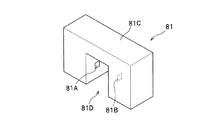
光センサ81は、搬送される用紙Pの幅内に配置されるように装置本体2に固定されており、図3に示すように、光を出射する発光素子81Aと、発光素子81Aから出射された光を受光する受光素子81Bと、発光素子81Aおよび受光素子81Bを支持する支持部材81Cとを備えている。支持部材81Cは、用紙Pの搬送方向に沿って貫通するとともに下方に向けて開口する溝81Dを有するコ字状の部材であり、この溝81Dを形成する面のうち対向する各面に発光素子81Aおよび受光素子81Bがそれぞれ互いに対向するように配設されている。
The
図2に示すように、アクチュエータ82は、主に、揺動軸82Aと、当接部82Bと、遮光片82Cと、対向片82Dとを備えて構成されており、全体がシート粉の一例としての紙粉を静電気により反発する材料で形成されている。ここで、「紙粉を反発する材料」とは、紙粉と同極性となる材料であり、例えば、ABS樹脂などが挙げられる。
As shown in FIG. 2, the
揺動軸82Aは、装置本体2に回動可能に支持されており、当接部82B、遮光片82Cおよび対向片82Dが径方向外側に延びるように一体に形成されている。すなわち、この揺動軸82Aは、当接部82B、遮光片82Cおよび対向片82Dを一体に支持しつつ、これらの揺動中心となっている。
The
また、揺動軸82Aは、光センサ81と用紙Pとの間に配置されている。詳しくは、揺動軸82Aは、光センサ81の溝81Dの下側に近接して配置されており、これにより、溝81Dの下側から溝81D内に侵入しようとしてくる紙粉が揺動軸82Aで撥ね返されるようになっている。さらに、揺動軸82Aの一部は、トーションバネ等の付勢部材で初期位置(用紙Pが通過していないときの位置)に付勢されており、これにより、当接部82B、遮光片82Cおよび対向片82Dが初期位置に復帰可能となっている。
In addition, the
当接部82Bは、図4(a)に示すように、初期位置において、揺動軸82Aから下方(用紙P側)へ向けて延び、用紙Pの先端と当接可能となっている。そして、この当接部82Bは、図4(b)に示すように、搬送される用紙Pの先端で押されることで、用紙Pの搬送方向下流側に向けて傾動するようになっている。
As shown in FIG. 4A, the
遮光片82Cは、図4(a)に示すように、初期位置において、揺動軸82Aから後斜め上方(光センサ81の後側)へ向けて延びており、前述した当接部82Bと一体に揺動(連動して移動)するようになっている。そして、この遮光片82Cの先端部は、受光素子81Bでの光の受光量を変化させる遮光部C1として機能している。
As shown in FIG. 4A, the
具体的に、遮光部C1は、用紙Pの非通過時には(図4(a)参照)、光センサ81の光路から外れた非遮光位置(受光量が最も大きくなる位置)に位置し、用紙Pの通過時には(図4(b)参照)、光センサ81の光路を塞ぐ遮光位置(受光量が最も小さくなる位置)に位置するようになっている。より詳しくは、遮光部C1は、遮光位置において光センサ81の溝81Dから前後にはみ出す長さで形成されている。そのため、この遮光位置においては、紙粉が溝81Dの前後の開口端に到達する前に、溝81Dからはみ出す遮光部C1によって紙粉が撥ね返されるようになっている。
Specifically, when the paper P does not pass (see FIG. 4A), the light shielding portion C1 is located at a non-light shielding position (a position where the amount of received light is maximized) that is out of the optical path of the
対向片82Dは、図4(a)に示すように、初期位置において、揺動軸82Aから前斜め上方(光センサ81の前側)へ向けて延びており、前述した当接部82Bと一体に揺動するようになっている。そして、この対向片82Dの先端部は、遮光部C1の揺動方向(移動方向)で遮光部C1と対向して、遮光部C1と一体的に揺動する対向部D1となっている。
As shown in FIG. 4A, the opposing
具体的に、遮光部C1と対向部D1は、遮光部C1が図4(a)の非遮光位置に位置するときに、光センサ81の光の光軸方向から見て光を挟んで対向するとともに、発光素子81Aおよび受光素子81Bに近接するように構成されている。言い換えると、図4(a)の非遮光位置では、光センサ81の溝81Dの前側(用紙搬送方向上流側)の開口に近接して対向部D1が配置され、溝81Dの後側(用紙搬送方向下流側)の開口に近接して遮光部C1が配置されている。そのため、溝81Dの前側の開口の一部が対向部D1で塞がれ、溝81Dの後側の開口の一部が遮光部C1で塞がれることで、溝81D内に紙粉が侵入し難くなっている。
Specifically, the light shielding portion C1 and the facing portion D1 face each other with the light viewed from the optical axis direction of the light of the
次に、アクチュエータ82の作用について説明する。
用紙Pがアクチュエータ82付近を通過する場合には、図4(a),(b)の順で示すように、用紙Pが当接部82Bを後方に押すことで当接部82Bが後方に揺動するとともに、これに連動して遮光片82Cが前方に揺動して、遮光部C1が光センサ81の溝81D内に入り込んで遮光位置に位置する。
Next, the operation of the
When the paper P passes through the vicinity of the
そのため、このような用紙Pの通過の際に、用紙Pから紙粉が発生した場合には、溝81D内に位置する遮光部C1によって紙粉を撥ね返すことができる。さらに、本実施形態では、遮光部C1が溝81Dから前後にはみ出しているので、紙粉が溝81Dに近接する前に紙粉を溝81Dから遠ざけるように撥ね返すことができる。
Therefore, when paper dust is generated from the paper P during the passage of the paper P, the paper dust can be repelled by the light shielding portion C1 located in the
用紙Pが当接部82Bから外れると、用紙Pで支持されていた当接部82Bが図示せぬ付勢部材の付勢力によって前方に揺動するとともに、遮光部C1と対向部D1が後方に揺動して、図4(a)に示すように、光センサ81の光(溝81D)を前後で挟み込むように位置する。そのため、用紙Pの通過後に依然として紙粉が舞っている場合であっても、溝81Dの前後に配置される遮光部C1と対向部D1によって、紙粉が溝81D内に入り込むのを抑えることができる。
When the paper P is removed from the
以上によれば、本実施形態において以下のような効果を得ることができる。
遮光部C1の位置に関わらず、紙粉を反発する材料で形成された遮光部C1単体もしくは遮光部C1および対向部D1の両方で、溝81D(発光素子81Aと受光素子81Bとの間)に入ろうとする紙粉を撥ね返すことができるので、光センサ81への紙粉の付着を抑制することができる。
According to the above, the following effects can be obtained in the present embodiment.
Regardless of the position of the light shielding portion C1, the
また、本実施形態に係るアクチュエータ82によれば、遮光部C1の位置に関わらず、光センサ81への紙粉の付着を抑制できるので、紙粉が多量に舞いやすい用紙Pの幅内であっても光センサ81を良好に作動させることができる。
In addition, according to the
アクチュエータ82の揺動軸82Aが紙粉を反発する材料で形成されることにより、用紙Pから光センサ81に向かう紙粉を、用紙Pと光センサ81の間にある揺動軸82Aで反発させることができるので、発光素子81A等に紙粉が付着するのをより抑えることができる。
By forming the
揺動軸82Aから用紙Pへ向けて延びる当接部82Bが紙粉を反発する材料で形成されることにより、用紙Pから揺動軸82Aに向かう紙粉を、用紙Pと揺動軸82Aの間にある当接部82Bで反発させることができるので、発光素子81A等に紙粉が付着するのをより抑えることができる。また、当接部82Bが、光センサ81の溝81D内に入る遮光部C1等に対して左側にずれた位置(軸方向で異なる位置)に配置されているので、当接部82Bよりも左側で発生した紙粉が、当接部82Bよりも右側の光センサ81に向かうのを当接部82Bの反発力によって抑えることができる。
The
用紙Pの通過によって最も紙粉が舞うときに、遮光部C1が遮光位置(発光素子81Aと受光素子81Bとの間)に位置するので、発光素子81A等への紙粉の付着をより抑制することができる。
Since the light shielding portion C1 is located at the light shielding position (between the light emitting
また、本実施形態に係るアクチュエータ82によれば、遮光部C1の位置に関わらず、光センサ81への紙粉の付着を抑制できるので、通常印字速度が高く、紙粉が舞いやすい電子写真方式のレーザプリンタ1内においても光センサ81を良好に作動させることができる。
In addition, according to the
なお、本発明は前記実施形態に限定されることなく、以下に例示するように様々な形態で利用できる。
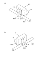
前記実施形態では、遮光片82Cの先端部を遮光部C1とし、対向片82Dの先端部を対向部D1としたが、本発明はこれに限定されるものではない。例えば、図5(a),(b)に示すように、前記実施形態の遮光片82Cや対向片82Dの変わりに、光を通すための孔91が外周面近傍(回転軸とは異なる位置)に形成された扇型状の回動部材90を設け、この回動部材90のうち孔91を周方向で挟んで対向する各部位を遮光部92および対向部93としてもよい。
In addition, this invention is not limited to the said embodiment, It can utilize with various forms so that it may illustrate below.
In the above embodiment, the tip of the
また、図5(a)に示すように、用紙Pが通過していないときに遮光部92が遮光位置に位置し、図5(b)に示すように、用紙Pが通過しているときに遮光部92が非遮光位置に位置するように構成してもよい。なお、この図5や後述する図6,7において、前記実施形態と同様の構造のものには、同一の符号を付して、その説明を省略する。
Further, as shown in FIG. 5A, the
また、図6,図7に示すように、前記実施形態における遮光片82Cの先端部(遮光部C1)と、対向片82Dの先端部(対向部D1)に、光センサ81の溝81Dの前後の開口を塞ぐための壁部C2,D2を設けてもよい。これによれば、溝81D内への紙粉の侵入をさらに抑制することができる。
Further, as shown in FIGS. 6 and 7, the front and back of the
前記実施形態では、遮光部C1と対向部D1を周方向に移動可能としたが、本発明はこれに限定されず、例えばピニオン・ラック機構を利用して遮光部・対向部を直線的に移動させてもよい。 In the above embodiment, the light shielding portion C1 and the facing portion D1 can be moved in the circumferential direction. However, the present invention is not limited to this. For example, the light shielding portion and the facing portion are moved linearly using a pinion rack mechanism. You may let them.
前記実施形態では、光を遮断する遮光位置と、光路から外れた非遮光位置との間で、遮光部C1を移動させたが、本発明はこれに限定されず、受光量が最も小さくなる位置と、受光量が最も大きくなる位置との間で遮光部を移動させればよい。すなわち、例えば、光を完全には遮断しない位置(受光量が小の位置)と、光路から完全には外れない位置(受光量が大の位置)との間で、遮光部を移動させてもよい。 In the above embodiment, the light shielding portion C1 is moved between the light shielding position where light is blocked and the non-light shielding position off the optical path. However, the present invention is not limited to this, and the position where the amount of received light is the smallest. And the light shielding part may be moved between the position where the amount of received light is the largest. That is, for example, even if the light shielding unit is moved between a position where light is not completely blocked (a position where the amount of received light is small) and a position where it is not completely removed from the optical path (a position where the amount of received light is large). Good.
前記実施形態では、遮光部C1および対向部D1と、当接部82Bとを揺動軸82Aの軸方向にオフセットした位置に別々に設けたが、本発明はこれに限定されず、遮光部、対向部および当接部を揺動軸の軸方向で同じ位置に一体に形成してもよい。また、このように一体となった遮光部、対向部および当接部が、回動しない揺動軸に対して回動可能に支持されるように構成されていてもよい。
In the embodiment, the light shielding part C1, the opposing part D1, and the
前記実施形態では、記録シート搬送装置として、レーザプリンタ1内で用紙Pを搬送させる機構を採用したが、本発明はこれに限定されず、例えば、原稿を搬送しながら読み取り可能な原稿読取装置の搬送機構を採用してもよい。 In the above-described embodiment, a mechanism for transporting the paper P in the laser printer 1 is employed as the recording sheet transporting device. However, the present invention is not limited to this, and for example, a document reading device capable of reading while transporting a document. A transport mechanism may be adopted.
前記実施形態では、画像形成装置として、電子写真方式のレーザプリンタ1に本発明を適用したが、本発明はこれに限定されず、その他の電子写真方式の画像形成装置(LEDを用いたプリンタ、複写機、複合機など)や、電子写真方式でない画像形成装置であってもよい。 In the above-described embodiment, the present invention is applied to the electrophotographic laser printer 1 as the image forming apparatus. However, the present invention is not limited to this, and other electrophotographic image forming apparatuses (printers using LEDs, A copying machine, a multifunction machine, etc.) or an image forming apparatus that is not an electrophotographic system.
前記実施形態では、記録シートの一例として、厚紙、はがき、薄紙などの用紙Pを採用したが、本発明はこれに限定されず、例えばOHPシートであってもよい。 In the above-described embodiment, paper P such as thick paper, postcard, and thin paper is used as an example of the recording sheet. However, the present invention is not limited to this, and may be, for example, an OHP sheet.
1 レーザプリンタ
8 用紙検知センサ
32 用紙搬送機構
81 光センサ
81A 発光素子
81B 受光素子
81C 支持部材
81D 溝
82 アクチュエータ
82A 揺動軸
82B 当接部
82C 遮光片
82D 対向片
C1 遮光部
D1 対向部
P 用紙
R 排紙ローラ
DESCRIPTION OF SYMBOLS 1 Laser printer 8
Claims (6)
記録シートの通過に連動して移動することで、前記受光素子での光の受光量を変化させる遮光部と、を備えた記録シート搬送装置であって、
前記遮光部の移動方向で前記遮光部と対向し、前記遮光部と一体的に移動する対向部を備え、
前記遮光部と前記対向部が、前記記録シートから発生するシート粉と同極性となる材料で形成され、
前記受光量が最も大きくなる位置に前記遮光部が位置するときに、前記遮光部と前記対向部が、前記光の光軸方向から見て前記光を挟んで対向するとともに、前記発光素子および前記受光素子に近接するように構成されていることを特徴とする記録シート搬送装置。 A light sensor that receives light emitted from the light emitting element by the light receiving element;
A recording sheet conveying apparatus comprising: a light shielding unit that changes a light reception amount of the light by the light receiving element by moving in conjunction with the passage of the recording sheet;
The light-shielding portion is opposed to the light-shielding portion in the moving direction of the light-shielding portion, and includes a facing portion that moves integrally with the light-shielding portion.
The light shielding portion and the facing portion are formed of a material having the same polarity as the sheet powder generated from the recording sheet,
When the light-shielding part is located at a position where the amount of received light is the largest, the light-shielding part and the facing part face each other with the light viewed from the optical axis direction of the light. A recording sheet conveying apparatus configured to be close to a light receiving element.
前記揺動軸が、前記シート粉と同極性となる材料で形成されていることを特徴とする請求項1または請求項2に記載の記録シート搬送装置。 An oscillation shaft disposed between the optical sensor and the recording sheet, supporting the light shielding portion and the opposing portion, and serving as an oscillation center of the light shielding portion and the opposing portion;
The recording sheet conveying apparatus according to claim 1, wherein the swing shaft is made of a material having the same polarity as the sheet powder.
前記当接部が、前記シート粉と同極性となる材料で形成されていることを特徴とする請求項3に記載の記録シート搬送装置。 A contact portion that extends from the swing shaft toward the recording sheet and is pressed at the tip of the recording sheet and swings together with the light shielding portion and the facing portion,
The recording sheet conveying apparatus according to claim 3, wherein the contact portion is formed of a material having the same polarity as the sheet powder.
Priority Applications (1)
| Application Number | Priority Date | Filing Date | Title |
|---|---|---|---|
| JP2009153426A JP4930552B2 (en) | 2009-06-29 | 2009-06-29 | Recording sheet conveying apparatus and image forming apparatus |
Applications Claiming Priority (1)
| Application Number | Priority Date | Filing Date | Title |
|---|---|---|---|
| JP2009153426A JP4930552B2 (en) | 2009-06-29 | 2009-06-29 | Recording sheet conveying apparatus and image forming apparatus |
Publications (2)
| Publication Number | Publication Date |
|---|---|
| JP2011006237A JP2011006237A (en) | 2011-01-13 |
| JP4930552B2 true JP4930552B2 (en) | 2012-05-16 |
Family
ID=43563393
Family Applications (1)
| Application Number | Title | Priority Date | Filing Date |
|---|---|---|---|
| JP2009153426A Expired - Fee Related JP4930552B2 (en) | 2009-06-29 | 2009-06-29 | Recording sheet conveying apparatus and image forming apparatus |
Country Status (1)
| Country | Link |
|---|---|
| JP (1) | JP4930552B2 (en) |
Families Citing this family (3)
| Publication number | Priority date | Publication date | Assignee | Title |
|---|---|---|---|---|
| JP2015112204A (en) * | 2013-12-10 | 2015-06-22 | シャープ株式会社 | Electric vacuum cleaner |
| JP6673655B2 (en) * | 2015-08-20 | 2020-03-25 | シャープ株式会社 | Sheet conveying apparatus and image forming apparatus having the same |
| JP7527048B1 (en) | 2023-06-13 | 2024-08-02 | 株式会社新川 | Substrate Transport Device |
Family Cites Families (4)
| Publication number | Priority date | Publication date | Assignee | Title |
|---|---|---|---|---|
| JPH082035A (en) * | 1994-06-24 | 1996-01-09 | Minolta Co Ltd | Paper feeder |
| JPH10231046A (en) * | 1997-02-21 | 1998-09-02 | Ricoh Co Ltd | Paper post-processing equipment |
| JP2002265144A (en) * | 2001-03-13 | 2002-09-18 | Sharp Corp | Paper transport device |
| JP4289095B2 (en) * | 2003-09-18 | 2009-07-01 | セイコーエプソン株式会社 | Image forming apparatus |
-
2009
- 2009-06-29 JP JP2009153426A patent/JP4930552B2/en not_active Expired - Fee Related
Also Published As
| Publication number | Publication date |
|---|---|
| JP2011006237A (en) | 2011-01-13 |
Similar Documents
| Publication | Publication Date | Title |
|---|---|---|
| JP5265509B2 (en) | Image forming apparatus and paper feeding apparatus | |
| JP5974736B2 (en) | Image forming apparatus | |
| JP4962558B2 (en) | Sheet feeding device | |
| JP4816677B2 (en) | Belt unit and image forming apparatus | |
| JP4930552B2 (en) | Recording sheet conveying apparatus and image forming apparatus | |
| JP4730449B2 (en) | Image forming apparatus | |
| JP6024157B2 (en) | Developer container | |
| JP2013250391A (en) | Image forming apparatus | |
| JP5724678B2 (en) | Image forming apparatus | |
| JP4876751B2 (en) | Image forming apparatus and process cartridge | |
| JP4645722B2 (en) | Fixing device | |
| JP4961899B2 (en) | Image forming apparatus | |
| CN104950646B (en) | image forming device | |
| JP5966627B2 (en) | Image forming apparatus | |
| JP5780014B2 (en) | Image forming apparatus | |
| JP5899709B2 (en) | Image forming apparatus | |
| JP5152247B2 (en) | Fixing apparatus and image forming apparatus | |
| JP2013097250A (en) | Transfer device | |
| CN102198890A (en) | Image-forming device | |
| JP2023098282A (en) | image forming device | |
| JP5805384B2 (en) | Image forming apparatus | |
| JP5098900B2 (en) | Image forming apparatus | |
| JP4158785B2 (en) | Image forming apparatus | |
| JP2019137485A (en) | Sheet conveying device and image forming device | |
| JP5093002B2 (en) | Image forming apparatus |
Legal Events
| Date | Code | Title | Description |
|---|---|---|---|
| A977 | Report on retrieval |
Free format text: JAPANESE INTERMEDIATE CODE: A971007 Effective date: 20111018 |
|
| A131 | Notification of reasons for refusal |
Free format text: JAPANESE INTERMEDIATE CODE: A131 Effective date: 20111025 |
|
| A521 | Request for written amendment filed |
Free format text: JAPANESE INTERMEDIATE CODE: A523 Effective date: 20111215 |
|
| TRDD | Decision of grant or rejection written | ||
| A01 | Written decision to grant a patent or to grant a registration (utility model) |
Free format text: JAPANESE INTERMEDIATE CODE: A01 Effective date: 20120117 |
|
| A01 | Written decision to grant a patent or to grant a registration (utility model) |
Free format text: JAPANESE INTERMEDIATE CODE: A01 |
|
| A61 | First payment of annual fees (during grant procedure) |
Free format text: JAPANESE INTERMEDIATE CODE: A61 Effective date: 20120130 |
|
| R150 | Certificate of patent or registration of utility model |
Ref document number: 4930552 Country of ref document: JP Free format text: JAPANESE INTERMEDIATE CODE: R150 Free format text: JAPANESE INTERMEDIATE CODE: R150 |
|
| FPAY | Renewal fee payment (event date is renewal date of database) |
Free format text: PAYMENT UNTIL: 20150224 Year of fee payment: 3 |
|
| LAPS | Cancellation because of no payment of annual fees |