JP4929740B2 - Audio conferencing equipment - Google Patents
Audio conferencing equipment Download PDFInfo
- Publication number
- JP4929740B2 JP4929740B2 JP2006023422A JP2006023422A JP4929740B2 JP 4929740 B2 JP4929740 B2 JP 4929740B2 JP 2006023422 A JP2006023422 A JP 2006023422A JP 2006023422 A JP2006023422 A JP 2006023422A JP 4929740 B2 JP4929740 B2 JP 4929740B2
- Authority
- JP
- Japan
- Prior art keywords
- sound
- signal
- input
- audio
- conference
- Prior art date
- Legal status (The legal status is an assumption and is not a legal conclusion. Google has not performed a legal analysis and makes no representation as to the accuracy of the status listed.)
- Expired - Fee Related
Links
Images


Classifications
-
- H—ELECTRICITY
- H04—ELECTRIC COMMUNICATION TECHNIQUE
- H04R—LOUDSPEAKERS, MICROPHONES, GRAMOPHONE PICK-UPS OR LIKE ACOUSTIC ELECTROMECHANICAL TRANSDUCERS; DEAF-AID SETS; PUBLIC ADDRESS SYSTEMS
- H04R3/00—Circuits for transducers, loudspeakers or microphones
- H04R3/12—Circuits for transducers, loudspeakers or microphones for distributing signals to two or more loudspeakers
-
- H—ELECTRICITY
- H04—ELECTRIC COMMUNICATION TECHNIQUE
- H04R—LOUDSPEAKERS, MICROPHONES, GRAMOPHONE PICK-UPS OR LIKE ACOUSTIC ELECTROMECHANICAL TRANSDUCERS; DEAF-AID SETS; PUBLIC ADDRESS SYSTEMS
- H04R3/00—Circuits for transducers, loudspeakers or microphones
- H04R3/005—Circuits for transducers, loudspeakers or microphones for combining the signals of two or more microphones
-
- H—ELECTRICITY
- H04—ELECTRIC COMMUNICATION TECHNIQUE
- H04R—LOUDSPEAKERS, MICROPHONES, GRAMOPHONE PICK-UPS OR LIKE ACOUSTIC ELECTROMECHANICAL TRANSDUCERS; DEAF-AID SETS; PUBLIC ADDRESS SYSTEMS
- H04R1/00—Details of transducers, loudspeakers or microphones
- H04R1/20—Arrangements for obtaining desired frequency or directional characteristics
- H04R1/32—Arrangements for obtaining desired frequency or directional characteristics for obtaining desired directional characteristic only
- H04R1/40—Arrangements for obtaining desired frequency or directional characteristics for obtaining desired directional characteristic only by combining a number of identical transducers
- H04R1/403—Arrangements for obtaining desired frequency or directional characteristics for obtaining desired directional characteristic only by combining a number of identical transducers loud-speakers
-
- H—ELECTRICITY
- H04—ELECTRIC COMMUNICATION TECHNIQUE
- H04R—LOUDSPEAKERS, MICROPHONES, GRAMOPHONE PICK-UPS OR LIKE ACOUSTIC ELECTROMECHANICAL TRANSDUCERS; DEAF-AID SETS; PUBLIC ADDRESS SYSTEMS
- H04R1/00—Details of transducers, loudspeakers or microphones
- H04R1/20—Arrangements for obtaining desired frequency or directional characteristics
- H04R1/32—Arrangements for obtaining desired frequency or directional characteristics for obtaining desired directional characteristic only
- H04R1/40—Arrangements for obtaining desired frequency or directional characteristics for obtaining desired directional characteristic only by combining a number of identical transducers
- H04R1/406—Arrangements for obtaining desired frequency or directional characteristics for obtaining desired directional characteristic only by combining a number of identical transducers microphones
-
- H—ELECTRICITY
- H04—ELECTRIC COMMUNICATION TECHNIQUE
- H04R—LOUDSPEAKERS, MICROPHONES, GRAMOPHONE PICK-UPS OR LIKE ACOUSTIC ELECTROMECHANICAL TRANSDUCERS; DEAF-AID SETS; PUBLIC ADDRESS SYSTEMS
- H04R2201/00—Details of transducers, loudspeakers or microphones covered by H04R1/00 but not provided for in any of its subgroups
- H04R2201/40—Details of arrangements for obtaining desired directional characteristic by combining a number of identical transducers covered by H04R1/40 but not provided for in any of its subgroups
- H04R2201/403—Linear arrays of transducers
-
- H—ELECTRICITY
- H04—ELECTRIC COMMUNICATION TECHNIQUE
- H04R—LOUDSPEAKERS, MICROPHONES, GRAMOPHONE PICK-UPS OR LIKE ACOUSTIC ELECTROMECHANICAL TRANSDUCERS; DEAF-AID SETS; PUBLIC ADDRESS SYSTEMS
- H04R2201/00—Details of transducers, loudspeakers or microphones covered by H04R1/00 but not provided for in any of its subgroups
- H04R2201/40—Details of arrangements for obtaining desired directional characteristic by combining a number of identical transducers covered by H04R1/40 but not provided for in any of its subgroups
- H04R2201/405—Non-uniform arrays of transducers or a plurality of uniform arrays with different transducer spacing
-
- H—ELECTRICITY
- H04—ELECTRIC COMMUNICATION TECHNIQUE
- H04R—LOUDSPEAKERS, MICROPHONES, GRAMOPHONE PICK-UPS OR LIKE ACOUSTIC ELECTROMECHANICAL TRANSDUCERS; DEAF-AID SETS; PUBLIC ADDRESS SYSTEMS
- H04R2430/00—Signal processing covered by H04R, not provided for in its groups
- H04R2430/20—Processing of the output signals of the acoustic transducers of an array for obtaining a desired directivity characteristic
-
- H—ELECTRICITY
- H04—ELECTRIC COMMUNICATION TECHNIQUE
- H04R—LOUDSPEAKERS, MICROPHONES, GRAMOPHONE PICK-UPS OR LIKE ACOUSTIC ELECTROMECHANICAL TRANSDUCERS; DEAF-AID SETS; PUBLIC ADDRESS SYSTEMS
- H04R3/00—Circuits for transducers, loudspeakers or microphones
- H04R3/02—Circuits for transducers, loudspeakers or microphones for preventing acoustic reaction, i.e. acoustic oscillatory feedback
Description
この発明は、ネットワーク等を介して複数の地点間で音声会議を行う音声会議装置、特にマイクとスピーカとが一体化された音声会議装置に関するものである。 The present invention relates to an audio conference apparatus that performs an audio conference between a plurality of points via a network or the like, and more particularly to an audio conference apparatus in which a microphone and a speaker are integrated.
従来、遠隔地間で音声会議を行う方法として、音声会議を行う地点毎に音声会議装置を設置して、これら装置をネットワークで接続し、音声信号を通信する方法が多く用いられている。そして、このような音声会議に利用される音声会議装置が各種考案されている。 2. Description of the Related Art Conventionally, as a method for conducting a voice conference between remote locations, a method of installing a voice conference device at each point where a voice conference is performed, connecting these devices via a network, and communicating a voice signal is often used. Various audio conference apparatuses used for such audio conferences have been devised.
特許文献1の音声会議装置は、ネットワークを介して入力される音声信号を天面に配置されたスピーカから放音し、側面に配置された異なる複数方向をそれぞれの正面方向とする各マイクで収音した音声信号を、ネットワークを介して外部に送信する。
The audio conferencing apparatus of
また、特許文献2の音声会議装置は、話者が自身のマイクを選択すると、このマイク位置に対応した擬似エコー信号を生成し、マイクに回り込んで収音される放音音声を打ち消して、該当する話者が発言した音声信号のみを、ネットワークを介して外部に送信する。
しかしながら、特許文献1や特許文献2の音声会議装置では、1つのスピーカから全方位に放音を行うため、放音指向性を細かく制御することができなかった。例えば、音声会議装置の周囲にいる話者の人数、すなわち一人であるのか、複数人いるのか等に基づいて最適な放音指向性を設定することができなかった。
However, in the audio conference apparatuses of
また、特許文献1や特許文献2の音声会議装置では、収音時に放音音声の影響を除去することはできるが、その他の話者音声以外のノイズの影響を効果的に除去することはできない。
Moreover, in the audio conference apparatuses of
さらには、これら特許文献1や特許文献2のような音声会議装置では、装置周りの環境(会議参加者数、会議室環境等)やネットワーク接続される他地点数等により設定される多様な放収音環境およびこの放収音環境の変化に対して、適切な対応を行うことができない。
Furthermore, in these audio conference apparatuses such as
したがって、この発明の目的は、放収音環境が多様な状況であり、これらが変化するような状況であっても、速やかに最適な放収音を行うことができる音声会議装置を提供することにある。 Accordingly, an object of the present invention is to provide an audio conference apparatus that can quickly and optimally emit and collect sound even in situations where the sound emission and collection environments are diverse and these conditions change. It is in.
この発明の音声会議装置は、設置面から筐体下面を所定距離離間させる脚部を備えた筐体の下面から外部方向を放音方向として前記下面に配列された複数のスピーカを備えたスピーカアレイと、入力音声信号に放音用信号処理を行って前記スピーカアレイの放音指向性を制御する放音制御手段と、前記筐体の側面から外部方向を収音方向として前記側面に配列された複数のマイクを備えたマイクアレイと、該マイクアレイで収音した収音音声信号に収音用信号処理を行って互いに異なる収音指向性を有する複数の収音ビーム信号を生成し、該複数の収音ビーム信号を比較して収音環境を検出するとともに特定の収音ビーム信号を選択して出力する収音制御手段と、前記入力音声信号と前記特定の収音ビーム信号とに基づいて、前記スピーカアレイから放音された音声が出力音声信号に含まれないように制御する回帰音除去手段と、前記入力音声信号数を検出し、該検出した数に応じて前記入力音声信号毎に異なる位置に仮想点音源を設定して、それぞれの仮想点音源から各入力音声信号が発散するような放音指向性を設定し、該設定した放音指向性を前記放音制御手段に与える制御手段と、を備えたことを特徴としている。 The audio conference apparatus according to the present invention includes a speaker array including a plurality of speakers arranged on the lower surface with the external direction as a sound emitting direction from the lower surface of the housing having a leg portion that separates the lower surface of the housing from the installation surface by a predetermined distance. And sound emission control means for performing sound emission signal processing on the input audio signal to control the sound emission directivity of the speaker array, and arranged on the side surface from the side surface of the housing as the sound collection direction. A microphone array including a plurality of microphones, and a plurality of sound collecting beam signals having different sound collecting directivities by performing sound collecting signal processing on the collected sound signals collected by the microphone array; A sound collection control means for detecting a sound collection environment by comparing the sound collection beam signals of the two and selecting and outputting a specific sound collection beam signal, and based on the input sound signal and the specific sound collection beam signal , The speaker door And regression sound elimination means sound that is emitted from Lee is controlled so as not included in the output audio signal, detecting the number of said input speech signal, a different position for each of the input audio signal in accordance with the number of the detected Control means for setting virtual point sound sources, setting sound emission directivity such that each input sound signal diverges from each virtual point sound source, and providing the set sound emission directivity to the sound emission control means; It is characterized by having.
そして、この発明の音声会議装置の回帰音除去手段は、入力音声信号の数だけ設けられ、各入力音声信号に基づいて擬似回帰音信号を生成し、特定の収音ビーム信号から擬似回帰音信号を減算することを特徴としている。または、この発明の音声会議装置の回帰音除去手段は、入力音声信号の数だけ設けられ、各入力音声信号と特定の収音ビーム信号とのレベルを比較する比較手段と、入力音声信号と特定の収音ビーム信号のうち比較手段によって信号レベルが低いと判断された信号のレベルを低減させるレベル低減手段と、を備えたことを特徴としている。 And the regression sound removing means of the audio conference apparatus according to the present invention is provided for the number of input audio signals, generates a pseudo regression sound signal based on each input audio signal, and generates a pseudo regression sound signal from a specific collected beam signal It is characterized by subtracting. Alternatively, the regression sound removing means of the audio conference apparatus according to the present invention is provided in the number corresponding to the number of input audio signals, the comparing means for comparing the levels of each input audio signal and a specific sound collecting beam signal, And a level reduction means for reducing the level of the signal whose signal level is determined to be low by the comparison means.
これらの構成では、他の音声会議装置から入力音声信号を受信すると、放音制御手段は、スピーカアレイの各スピーカから放音される音声により放音ビームが形成されるように遅延制御等の放音用信号処理を行う。ここで、放音ビームとしては、室内の所定方向で所定距離、例えば会議者が着席している位置に音が収束する設定のサウンドビームや、或る特定位置に仮想点音源が存在し、この仮想点音源から発散させて放音する設定のサウンドビームなどがある。各スピーカは、放音制御手段から与えられる放音信号を室内へ放音する。これにより所望の放音指向性からなる放音が実現される。スピーカから放音された音声は、設置面を反射して、装置横方向の話者側に伝搬される。 In these configurations, when an input audio signal is received from another audio conferencing apparatus, the sound emission control means emits sound such as delay control so that a sound emission beam is formed by the sound emitted from each speaker of the speaker array. Perform sound signal processing. Here, as the sound emission beam, there is a sound beam that is set to converge at a predetermined distance in a predetermined direction in the room, for example, a position where the conference person is seated, or a virtual point sound source at a certain specific position. There is a sound beam that emits sound from a virtual point source. Each speaker emits a sound emission signal given from the sound emission control means into the room. As a result, sound emission having a desired sound emission directivity is realized. The sound emitted from the speaker is reflected on the installation surface and propagated to the speaker side in the lateral direction of the apparatus.
マイクアレイの各マイクは筐体の側面に設置され側面方向からの音を収音し、収音信号を収音制御手段に出力する。このようにスピーカアレイとマイクアレイとが筐体の異なる面に存在することで、スピーカからマイクへの回り込み音が低減される。収音制御手段は、各収音信号に遅延処理等を行って、側面方向のそれぞれに異なる方向に強い指向性を有する複数の収音ビーム信号を生成する。これにより、各収音ビーム信号ではさらに回り込み音が抑圧される。収音制御手段は、各収音ビーム信号の信号レベル等を比較して、特定の収音ビーム信号を選択して、回帰音除去手段に出力する。回帰音除去手段は、入力音声信号と特定の収音ビーム信号とに基づいてスピーカアレイから放音されてマイクロホンに回り込む音声を出力音声信号に含ませない処理を行う。具体的には、回帰音除去手段は、入力音声信号に基づく擬似回帰音信号を生成し、特定の収音ビーム信号から擬似回帰音信号を減算することで、回り込み音声を抑圧する。または、回帰音除去手段は、入力音声信号と特定の収音ビーム信号との信号レベルを比較して、入力音声信号の信号レベルが高ければ、主に受話中であると判断して特定の収音ビーム信号の信号レベルを低減し、特定の収音ビーム信号の信号レベルが高ければ、主に送話中であると判断して入力音声信号の信号レベルを低減する。 Each microphone of the microphone array is installed on the side surface of the housing, collects sound from the side surface direction, and outputs a sound collection signal to the sound collection control means. In this way, the speaker array and the microphone array are present on different surfaces of the housing, so that the noise from the speaker to the microphone is reduced. The sound collection control means performs a delay process or the like on each sound collection signal, and generates a plurality of sound collection beam signals having strong directivities in different directions in the lateral direction. As a result, the wraparound sound is further suppressed in each collected beam signal. The sound collection control means compares the signal level of each sound collection beam signal, etc., selects a specific sound collection beam signal, and outputs it to the regression sound removal means. The regression sound removal means performs processing that does not include in the output sound signal the sound that is emitted from the speaker array and circulates into the microphone based on the input sound signal and the specific sound collection beam signal. Specifically, the regression sound removing means generates a pseudo regression sound signal based on the input speech signal, and subtracts the pseudo regression sound signal from a specific sound collection beam signal, thereby suppressing the wraparound speech. Alternatively, the regression sound removal means compares the signal levels of the input sound signal and the specific sound collection beam signal, and if the signal level of the input sound signal is high, the regression sound removal means mainly determines that the call is being received and performs a specific sound collection. If the signal level of the sound beam signal is reduced and the signal level of the specific sound collection beam signal is high, it is determined that the voice is being transmitted mainly and the signal level of the input voice signal is reduced.
このような構成により、回り込み音の収音量が低減され、回帰音除去手段による処理負荷が軽減されるとともに、素早く出力音声信号が最適化される。また、放音ビームで仮想点音源を実現する場合、前記回帰音の低減とともに、臨場感の有る会議が実現される。また、放音ビームを収束性にすれば、放音ビームにより放音音声が制御され、収音ビームにより収音音声が制御されることから、回り込み音の収音量が大幅に抑圧され、回帰音除去手段による処理負荷が大幅に軽減されるとともに、より素早く出力音声信号が最適化される。このように、本発明の構成を用いることで、会議者数や接続会議地点数等の会議環境に応じて、最適な放収音が簡単に実現される。
また、この構成では、制御手段は、入力音声信号数を検出し、この検出数からネットワークを介して会議に参加している音声会議装置数を検出する。そして、接続している音声会議装置数に応じて、放音指向性を設定する。具体的には、音声会議装置接続数が一つであって、会議者が一対一の場合であれば、特に仮想点音源を必要とせず、前述の収束性の放音を行って、当該会議者にのみ音声を放音させる。これに対して、一つの音声会議装置を使用する会議者が複数の場合は、仮想点音源を該音声会議装置の略中央位置に設定して放音させる。一方、音声会議装置接続数が複数であれば、複数の仮想点音源の設定を行う等して、臨場感のある音声を放音させたり、後述するように接続先毎に異なる方向に放音音声を収束させる。
With such a configuration, the volume of the wraparound sound is reduced, the processing load of the regression sound removing means is reduced, and the output audio signal is quickly optimized. Further, when a virtual point sound source is realized by a sound output beam, a meeting with a sense of reality is realized along with the reduction of the return sound. Also, if the sound emission beam is made convergent, the sound output is controlled by the sound output beam, and the sound pickup sound is controlled by the sound collection beam. The processing load due to the removing means is greatly reduced, and the output audio signal is optimized more quickly. Thus, by using the configuration of the present invention, the optimum sound emission and collection can be easily realized according to the conference environment such as the number of conferences and the number of connected conference points.
In this configuration, the control means detects the number of input voice signals, and detects the number of voice conference apparatuses participating in the conference via the network from the detected number. Then, the sound emission directivity is set according to the number of connected audio conference apparatuses. Specifically, if the number of connected audio conferencing apparatuses is one and the number of conferencing members is one-to-one, a virtual point sound source is not required and the convergence sound emission is performed, and the conference is performed. Let the person emit sound. On the other hand, when there are a plurality of conference persons who use one audio conference apparatus, the virtual point sound source is set at a substantially central position of the audio conference apparatus and the sound is emitted. On the other hand, if there are multiple audio conferencing device connections, sound with realistic sensation can be emitted by setting multiple virtual point sound sources, etc., or emitted in different directions for each connection destination as will be described later. Converge the voice.
また、この発明の音声会議装置は、筐体が一方向に長尺な略直方体形状であり、複数のスピーカおよび複数のマイクが長尺な方向に沿って配列されていることを特徴としている。 The voice conference apparatus of the present invention is characterized in that the casing has a substantially rectangular parallelepiped shape that is long in one direction, and a plurality of speakers and a plurality of microphones are arranged along the long direction.
この構成では、具体的な筐体の構造として長尺な略直方体形状を用いる。この構造で長尺方向にスピーカおよびマイクを配置することで、直線状にスピーカが配列されたスピーカアレイと、直線状にマイクが配列されたマイクアレイとが効率的に配置される。 In this configuration, a long, substantially rectangular parallelepiped shape is used as a specific housing structure. By arranging the speaker and the microphone in the longitudinal direction with this structure, the speaker array in which the speakers are arranged in a straight line and the microphone array in which the microphones are arranged in a straight line are efficiently arranged.
また、この発明の音声会議装置は、制御手段で、入力音声信号の履歴と収音環境との履歴とを記憶し、双方の履歴に基づいて入力音声信号と収音環境の変化との関連性を検出し、該関連性に基づいて放音制御手段に推定した放音指向性を与えるとともに、収音制御手段に推定した収音環境に応じた収音ビーム信号の選択制御を与えることを特徴としている。 In the audio conference apparatus of the present invention, the control means stores the history of the input audio signal and the history of the sound collection environment, and the relationship between the input audio signal and the change of the sound collection environment based on both the history. And the sound emission directivity estimated to the sound emission control means based on the relation, and the sound collection beam signal selection control according to the estimated sound collection environment is given to the sound collection control means. It is said.
この構成では、制御手段は、入力音声信号の履歴すなわち接続先の履歴と、収音環境の履歴とを記憶し、これらの関連性を検出する。例えば、本装置に対して第1の方向にいる話者は第1の接続先と会話をし、本装置に対して第2の方向にいる話者は第2の接続先と会話をしている、という情報を取得する。そして、制御手段は、対応する話者へのみ音声が放音されるように入力音声信号(接続先)毎に収束性の放音指向性を設定する。また、制御手段は、対応する話者方向でのみ収音するように出力音声信号(接続先)毎に収音ビーム選択(収音指向性)を設定する。これにより、1つの音声会議装置で並行して複数の音声会議が実現され、互いの会議音声同士が干渉し合わない。 In this configuration, the control means stores the history of the input audio signal, that is, the history of the connection destination and the history of the sound collection environment, and detects the relationship between them. For example, a speaker in the first direction with respect to the device has a conversation with the first connection destination, and a speaker in the second direction with respect to the device has a conversation with the second connection destination. Information that it is. And a control means sets the sound emission directivity of convergence for every input audio | voice signal (connection destination) so that an audio | voice is emitted only to a corresponding speaker. Further, the control means sets the sound collection beam selection (sound collection directivity) for each output audio signal (connection destination) so as to collect sound only in the corresponding speaker direction. Thereby, a plurality of audio conferences are realized in parallel by one audio conference apparatus, and the conference audios do not interfere with each other.
この発明によれば、音声会議に参加する地点数や、1つの音声会議装置を使用する会議者数等による様々な音声会議の形式や環境に対して、唯一台の音声会議装置により最適な音声会議を実現することができる。 According to the present invention, a single audio conferencing apparatus can provide optimal audio for various audio conferencing formats and environments depending on the number of locations participating in an audio conference and the number of participants using one audio conferencing apparatus. A meeting can be realized.
本発明の実施形態に係る音声会議装置について、図を参照して説明する。 An audio conference apparatus according to an embodiment of the present invention will be described with reference to the drawings.
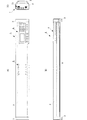
図1は本実施形態の音声会議装置を表す三面図であり、(A)が平面図、(B)が正面図(長尺の側面側から見た図)、(C)が側面図(短尺側の側面から見た図)である。
図2は、図1に示す音声会議装置のスピーカ配列およびマイク配列を示した図であり、(A)が正面図(図1(B)に相当)、(B)が底面図、(C)が裏面図(図1(B)の反対側の面に相当)である。
図3は本実施形態の音声会議装置の機能ブロック図である。
1A and 1B are three views showing the audio conference apparatus of the present embodiment, in which FIG. 1A is a plan view, FIG. 1B is a front view (viewed from the long side), and FIG. 1C is a side view (short). The figure seen from the side of the side).
2 is a diagram showing a speaker arrangement and a microphone arrangement of the audio conference apparatus shown in FIG. 1, in which (A) is a front view (corresponding to FIG. 1 (B)), (B) is a bottom view, and (C). Is a rear view (corresponding to the opposite surface of FIG. 1B).
FIG. 3 is a functional block diagram of the audio conference apparatus according to the present embodiment.
図1、図2に示すように、本実施形態の音声会議装置1は、機構的に、筐体2、脚部3、操作部4、発光部5、入出力コネクタ11を備える。
筐体2は一方向に長尺な略直方体形状からなり、筐体2の長尺な辺(面)の両端部には、筐体2の下面を設置面から所定間隔離間する所定高さの脚部3が設置されている。なお、以下の説明では、筐体2の四側面のうち、長尺な面を長尺面、短尺な面を短尺面と称する。
As shown in FIGS. 1 and 2, the
The
筐体2の上面における長尺な方向の一方端には、複数のボタンや表示画面からなる操作部4が設置されている。これら操作部4は筐体2内に設置された制御部10に接続し、会議者からの操作入力を受け付けて、制御部10に出力するとともに、操作内容や実行モード等を表示画面に表示する。筐体2の上面中央部には、一点を中心として放射状に配置されたLED等の発光素子からなる発光部5が設置されている。発光部5は、制御部10からの発光制御に応じて発光する。例えば、話者方向を示す発光制御が入力されれば、その方向に対応する発光素子を発光する。
An
筐体2における操作部4が設置された側の短尺面には、LANインターフェース、アナログオーディオ入力端子、アナログオーディオ出力端子、デジタルオーディオ入出力端子を備える入出力コネクタ11が設置されており、この入出力コネクタ11は筐体2内部に設置された入出力I/F12に接続する。また、LANインターフェースにネットワークケーブルを装着し、ネットワークに接続することで、ネットワーク上の他の音声会議装置に接続する。
An input /
筐体2の下面には、同形状からなるスピーカSP1〜SP16が設置されている。これらスピーカSP1〜SP16は長尺方向に沿って一定の間隔で直線状に設置されており、これによりスピーカアレイが構成される。筐体2の一方の長尺面には、同形状からなるマイクMIC101〜MIC116が設置されている。これらマイクMIC101〜MIC116は長尺方向に沿って一定の間隔で直線状に設置されており、これによりマイクアレイが構成される。また、筐体2の他方の長尺面にも、同形状からなるマイクMIC201〜MIC216が設置されている。これらマイクMIC201〜MIC216も長尺方向に沿って一定の間隔で直線状に設置されており、これによりマイクアレイが構成される。そして、筐体2の下面側には、これらスピーカアレイおよびマイクアレイを覆う形状で形成され、パンチメッシュされた下面グリル6が設置されている。なお、本実施形態では、スピーカアレイのスピーカ数を16本とし、各マイクアレイのマイク数をそれぞれ16本としたが、これに限ることなく、仕様に応じてスピーカ数およびマイク数は適宜設定すればよい。また、スピーカアレイおよびマイクアレイの間隔は一定ではなくてもよく、例えば、長尺方向に沿って中央部で密に配置され、両端部にいくに従い疎に配置されるような態様でもよい。
Speakers SP <b> 1 to SP <b> 16 having the same shape are installed on the lower surface of the
次に、図3に示すように、本実施形態の音声会議装置1は、機能的に、制御部10、入出力コネクタ11、入出力I/F12、放音指向性制御部13、D/Aコンバータ14、放音用アンプ15、スピーカアレイ(スピーカSP1〜SP16)、マイクアレイ(マイクMIC101〜MIC116,MIC201〜MIC216)、収音用アンプ16、A/Dコンバータ17、収音ビーム生成部181、収音ビーム生成部182、収音ビーム選択部19、エコーキャンセル部20、操作部4を備える。
Next, as shown in FIG. 3, the
入出力I/F12は、入出力コネクタ11を介して入力された、他の音声会議装置からの入力音声信号をネットワークに対応するデータ形式(プロトコル)から変換して、エコーキャンセル部20を介して放音指向性制御部13に与える。この際、入出力I/F12は、複数の音声会議装置から入力音声信号を受信すると、これらを音声会議装置毎に識別して、それぞれ異なる伝送経路でエコーキャンセル部20を介して放音指向性制御部13に与える。また、入出力I/F12は、エコーキャンセル部20で生成される出力音声信号をネットワークに対応するデータ形式(プロトコル)に変換して、入出力コネクタ11を介して、ネットワークに送信する。
The input / output I /
放音指向性制御部13は、指定された放音指向性に基づいて、スピーカアレイの各スピーカSP1〜SP16にそれぞれ固有の遅延処理及び振幅処理等を入力音声信号に対して行い個別放音信号を生成する。ここで、放音指向性としては、音声会議装置1の長尺な方向における所定位置で放音音声を収束させるものや、仮想点音源を設定して当該仮想点音源から放音音声を発散させるものがあり、これら放音指向性をスピーカSP1〜SP16からの放音音声で実現するような個別放音信号が生成される。
The sound emission
そして、放音指向性制御部13は、これら個別放音信号をスピーカSP1〜SP16毎に設置されたD/Aコンバータ14に出力する。各D/Aコンバータ14は個別放音信号をアナログ形式に変換して各放音用アンプ15に出力し、各放音用アンプ15は個別放音信号を増幅してスピーカSP1〜SP16に与える。
And the sound emission
スピーカSP1〜SP16は、無指向性のスピーカからなり、与えられた個別放音信号を音声変換して外部に放音する。この際、スピーカSP1〜SP16は筐体2の下面に設置されているので、放音された音声は、音声会議装置1が設置される机の設置面を反射して、会議者のいる装置の横から斜め上方に向かって伝搬される。
The speakers SP1 to SP16 are omnidirectional speakers, which convert a given individual sound emission signal into sound and emit the sound outside. At this time, since the speakers SP1 to SP16 are installed on the lower surface of the
マイクアレイの各マイクMIC101〜MIC116、MIC201〜216は、無指向性であっても有指向性であってもよいが、有指向性であることが望ましく、音声会議装置1の外部からの音声を収音して電気変換し、収音信号を各収音用アンプ16に出力する。各収音用アンプ16は、収音信号を増幅してそれぞれA/Dコンバータ17に与え、A/Dコンバータ17は、収音信号をデジタル変換して収音ビーム生成部181,182に出力する。ここで、収音ビーム生成部181には、一方の長尺面に設置されたマイクMIC101〜MIC116での収音信号が入力され、収音ビーム生成部182には、他方の長尺面に設置されたマイクMIC201〜MIC216での収音信号が入力される。
Each of the microphones MIC101 to MIC116 and MIC201 to 216 of the microphone array may be omnidirectional or directional. However, it is desirable that the microphones be directional, and audio from the outside of the
図4は本実施形態に係る音声会議装置1の収音ビームMB11〜MB14,MB21〜MB24の分布を示した平面図である。
FIG. 4 is a plan view showing the distribution of the collected sound beams MB11 to MB14 and MB21 to MB24 of the
収音ビーム生成部181は、各マイクMIC101〜MIC116の収音信号に対して所定の遅延処理等を行い、収音ビーム信号MB11〜MB14を生成する。収音ビーム信号MB11〜MB14は、マイクMIC101〜MIC116が設置された長尺面側で、当該長尺面に沿って、それぞれに異なる所定領域が収音強度の中心に設定されている。
The collected sound
収音ビーム生成部182は、各マイクMIC201〜MIC216の収音信号に対して所定の遅延処理等を行い、収音ビーム信号MB21〜MB24を生成する。収音ビーム信号MB21〜MB24は、マイクMIC201〜MIC216が設置された長尺面側で、当該長尺面に沿って、それぞれに異なる所定領域が収音強度の中心に設定されている。
The collected
収音ビーム選択部19は、収音ビーム信号MB11〜MB14,MB21〜MB24を入力して信号強度を比較、予め設定した所定条件に適合する収音ビーム信号MBを選択する。例えば、一人の話者からの音声のみを他の音声会議装置に送信する場合には、収音ビーム選択部19は、最も信号強度の高い収音ビーム信号を選択し、特定収音ビーム信号MBとしてエコーキャンセル部20に出力する。また、複数の音声会議を並行して行う時のように複数の収音ビーム信号が必要であれば、その状況に応じた収音ビーム信号を順次選択して、それぞれを個別の特定収音ビーム信号MBとしてエコーキャンセル部20に出力する。また、収音ビーム選択部19は、選択した特定収音ビーム信号MBに対応する収音方向(収音指向性)を含む収音環境情報を制御部10に出力する。制御部10はこの収音環境情報に基づき、話者方向を特定し、放音指向性制御部13に与える放音指向性を設定する。
The collected sound
エコーキャンセル部20は、それぞれに独立なエコーキャンセラ21〜23が設置されており、これらが直列接続された構造からなる。すなわち、収音ビーム選択部19の出力はエコーキャンセラ21に入力され、エコーキャンセラ21の出力はエコーキャンセラ22に入力される。そして、エコーキャンセラ22の出力はエコーキャンセラ23に入力され、エコーキャンセラ23の出力は入出力I/F12に入力される。
The
エコーキャンセラ21は適応型フィルタ211とポストプロセッサ212とを備える。また、図示していないが、エコーキャンセラ22,23は、エコーキャンセラ21と同じ構成からなり、それぞれ適応型フィルタ221,231とポストプロセッサ222,232とを備える。
The
エコーキャンセラ21の適応型フィルタ211は、入力音声信号S1に対して、設定される放音指向性と選択される特定収音ビーム信号MBの収音指向性とに基づく擬似回帰音信号を生成する。ポストプロセッサ212は、収音ビーム選択部19から出力される特定収音ビーム信号から、入力音声信号S1に対する擬似回帰音信号を減算して、エコーキャンセラ22のポストプロセッサ222に出力する。
The
エコーキャンセラ22の適応型フィルタ221は、入力音声信号S2に対して、設定される放音指向性と選択される特定収音ビーム信号MBの収音指向性とに基づく擬似回帰音信号を生成する。ポストプロセッサ222は、エコーキャンセラ21のポストプロセッサ212から出力される第1減算信号から、入力音声信号S2に対する擬似回帰音信号を減算して、エコーキャンセラ23のポストプロセッサ232に出力する。
The adaptive filter 221 of the echo canceller 22 generates a pseudo-regression sound signal based on the set sound emission directivity and the sound collection directivity of the selected specific sound collection beam signal MB with respect to the input sound signal S2. . The
エコーキャンセラ23の適応型フィルタ231は、入力音声信号S3に対して、設定される放音指向性と選択される特定収音ビーム信号MBの収音指向性とに基づく擬似回帰音信号を生成する。ポストプロセッサ232は、エコーキャンセラ22のポストプロセッサ222から出力される第2減算信号から、入力音声信号S3に対する擬似回帰音信号を減算して、出力音声信号として入出力I/F12に出力する。ここで、入力音声信号が1つであれば、エコーキャンセラ21〜23のいずれかが動作し、入力音声信号が2つであれば、エコーキャンセラ21〜23のいずれか二つが動作する。
The adaptive filter 231 of the
このようなエコーキャンセル処理を行うことにより、適切なエコー除去が行われ、自装置の話者音声のみが出力音声信号として、ネットワークに送信される。この際、放音ビーム処理と収音ビーム処理とが行われた上で、エコーキャンセル処理が行われるので、単に無指向性のスピーカを備える場合や、無指向性のマイクを備える場合よりも、回り込み音を抑圧することができる。さらに、機構的に、前述のようにスピーカとマイクとの間で回り込みが発生しにくい構造であるので、より回り込み音声の抑圧効果が向上するとともに、機構的に回り込みの発生が少ない分、エコーキャンセル処理の処理負荷が低減し、より高速に最適な出力音声信号を生成することができる。 By performing such echo cancellation processing, appropriate echo cancellation is performed, and only the speaker voice of the own apparatus is transmitted to the network as an output voice signal. At this time, since the echo canceling process is performed after the sound emitting beam processing and the sound collecting beam processing are performed, rather than simply including an omnidirectional speaker or a case of including an omnidirectional microphone, A wraparound sound can be suppressed. Furthermore, mechanically, as described above, the structure is such that wraparound is less likely to occur between the speaker and the microphone, so that the effect of suppressing wraparound sound is further improved, and echo cancellation is reduced because of less mechanical wraparound. The processing load of processing is reduced, and an optimal output audio signal can be generated at higher speed.
次に、このような構成および処理を行う音声会議装置の使用例について、図を参照して説明する。なお、以下に挙げる例は、使用方法の一部であり、これらに類似の使用方法においても本発明の構成および処理が適用することができる。 Next, a usage example of an audio conference apparatus that performs such a configuration and processing will be described with reference to the drawings. Note that the following examples are a part of usage methods, and the configuration and processing of the present invention can be applied to similar usage methods.
(1)ネットワークを介して接続している他の音声会議装置の数が1つの場合
接続している他の音声会議装置が1つの場合、すなわち音声会議装置が一対一で音声会議を行う場合、入出力I/F12が受信する入力音声信号は1つであり、制御部10は、これを検出して、他の音声会議装置が1つであることを検出する。
(1) When the number of other audio conference apparatuses connected via the network is one When the number of other audio conference apparatuses connected is one, that is, when the audio conference apparatus performs a one-on-one audio conference, The input / output I /
また、この入力音声信号の検出とは別の通常処理として、収音ビーム選択部19は、前述のように、各収音ビーム信号から特定収音ビーム信号を選択するとともに、収音環境情報を生成する。制御部10は、収音環境情報を取得して話者方向を検出し、所定の放音指向性制御を行う。例えば、話者に放音音声を収束させて、他の領域に放音音声を伝搬しないような設定を行う場合には、検出した話者方向に収束する放音ビーム信号を形成する放音指向性制御を行う。これにより、会議に関係しない多数の人が無作為にいるような空間内で会議を行っていても、話者からの音声のみを高いS/N比で収音するだけでなく、話者にのみ相手会議者の音声を放音し、他の人にこの音声が漏れることを防止することができる。
In addition, as a normal process different from the detection of the input sound signal, the sound collection
ところで、この方法では、会議者が複数人いる場合には、話者のみしか相手会議者の音声を聞くことができなくなる。 By the way, in this method, when there are a plurality of conference persons, only the speaker can hear the voice of the other party.
したがって、このような場合には、放音指向性を他の方法で制御すればよい。 Therefore, in such a case, the sound emission directivity may be controlled by another method.
図5(A)は一人の会議者Aが音声会議装置1で会議をする場合を示し、図5(B)は二人の会議者A,Bが音声会議装置1で会議をし、会議者Aが話者となっている場合を示す図である。
FIG. 5A shows a case in which one conference person A has a meeting with the
図5(A)に示すように、会議者がA一人である場合は、当然会議者Aが話者となる。収音ビーム選択部19は、収音信号から会議者Aの存在する方向を指向性の中心とする収音ビーム信号MB13を選択し、この収音環境情報を制御部10に与える。制御部10は、話者方向を検出する。そして、制御部10は、図5(A)に示すように、検出した話者A方向にのみ放音を行う放音指向性を設定する。これにより、話者Aのみに相手会議者の音声を放音し、他の領域に会議音が伝搬する(漏れる)ことを防止することができる。
As shown in FIG. 5A, when there is only one person A, the person A is naturally the speaker. The collected sound
一方、図5(B)に示すように、会議者がA,Bの二人であり、会議者Aが話者となると、収音ビーム選択部19は、会議者Aの存在する方向を指向性の中心とする収音ビーム信号MB13を選択し、この収音環境情報を制御部10に与える。制御部10は、話者方向を検出するとともに、今回の話者方向より以前に検出した話者方向を記憶しておき、その話者方向を読み出して会議者方向として検出する。図5(B)の例であれば、会議者Bの方向を会議者方向として検出する。
On the other hand, as shown in FIG. 5B, when there are two persons A and B and the person A becomes a speaker, the sound
そして、制御部10は、図5(B)に示すように、検出した話者A方向および会議者B方向に同等に放音されるように、音声会議装置1の長尺方向の中心に仮想点音源901が位置するような放音指向性を設定する。これにより、その時点での話者Aのみでなく、会議者Bへ同等に相手会議者の音声を放音することができる。
Then, as shown in FIG. 5 (B), the
このように、話者の切り替えに応じて収音指向性(特定収音ビーム信号)を切り替えるとともに、放音指向性を切り替えることで、互いの会議者全員に対して音声が聞き取りやすい音声会議を実現することができる。そして、本装置は、スピーカアレイとマイクアレイとを同時に備えていることにより、この音声会議を容易に行うことができる。 In this way, by switching the sound collection directivity (specific sound collection beam signal) according to the switching of the speaker, and switching the sound emission directivity, it is possible to make an audio conference that makes it easy to hear all of the participants. Can be realized. And this apparatus can perform this audio conference easily by providing the speaker array and the microphone array at the same time.
なお、前述のように制御部10が話者方向を記憶しておくことにより、制御部10は、その時点から以前の所定期間内の話者方向を読み出し、主に設定されている話者方向を検出することができる。制御部10は、この話者方向が限定的であることを検出すると、収音ビーム選択部19に、対応する収音ビーム信号でのみ選択処理を行う指示をする。収音ビーム選択部19は、この指示に従い、該当する収音ビーム信号でのみ選択処理を行い、エコーキャンセル部20に出力する。例えば、常時一方向からのみ話者音声が収音されるのであれば、この一方向の収音ビーム信号に固定し、二方向でのみ話者方向が収音されるのであれば、これら二方向の収音ビーム信号でのみ選択処理を行う。このような処理を行うことで、収音ビーム選択処理負荷が低減されて、より素早く出力音声信号を生成することができる。
As described above, when the
(2)ネットワークを介して接続している他の音声会議装置の数が複数の場合
接続している他の音声会議装置の数が複数の場合、入出力I/F12が受信する入力音声信号は複数であり、制御部10は、これを検出して、他の音声会議装置が複数あることを検出する。そして、制御部10は、各音声会議装置に対してそれぞれ異なる位置を仮想点音源に設定して、それぞれの仮想点音源から各入力音声信号が発声し発散するような放音指向性を設定する。
(2) When there are a plurality of other audio conference apparatuses connected via the network When there are a plurality of other audio conference apparatuses connected, the input audio signal received by the input / output I /
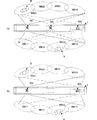
図6(A)は3つの仮想点音源を設定した場合の放音状態を示す概念図である。また、図6(B)は2つの仮想点音源を設定した場合の放音状態を示す概念図である。図6において、実線は仮想点音源901からの放音音声を示し、破線は仮想点音源902からの放音音声を示し、二点鎖線は仮想点音源903からの放音音声を示す。
FIG. 6A is a conceptual diagram showing a sound emission state when three virtual point sound sources are set. FIG. 6B is a conceptual diagram showing a sound emission state when two virtual point sound sources are set. In FIG. 6, a solid line indicates sound emitted from the virtual point
例えば、入力音声信号が3個であれば、図6(A)に示すように、それぞれの入力音声信号に応じた仮想点音源901,902,903を設定する。この際、仮想点音源901,903を筐体1の長尺方向の対向する両端部に対応させ、仮想点音源902を筐体1の長尺方向の中央部に対応させる。この設定に基づいて放音指向性を設定し、放音指向性制御部13で、遅延制御および振幅制御等により各スピーカSP1〜SP16の個別放音信号を生成する。そして、スピーカSP1〜SP16が個別放音信号を放音することで、異なる3箇所の仮想点音源901〜903からそれぞれ音声を発声させた状態を形成することができる。一方、入力音声信号が2個であれば、図6(B)に示すように、それぞれの入力音声信号に応じた仮想点音源901,902を設定する。この際、仮想点音源901,902を筐体1の長尺方向の対向する両端部に対応させる。この設定に基づいて放音指向性を設定することで、今度は異なる2箇所の仮想点音源901,902からそれぞれ音声を発声させた状態を形成することができる。なお、これら仮想点音源の位置は、予め固定位置に設定しておいてもよい。
For example, if there are three input audio signals, virtual point
これらの切り替えは、制御部10の放音指向性設定の切り替えのみで行うことができるので、接続された他の音声会議装置の数、すなわち接続環境に応じて、容易に最適な放音環境(放音指向性)を実現することができる。そして、このような仮想点音源を設定することで、より臨場感の有る会議を行うことができる。なお、この際、放音音声は発散するため、若干は収音されるが、エコーキャンセル部20に予め仮想点音源用の初期パラメータを与えておくことで、回帰音を効果的に除去することができる。
Since these switching operations can be performed only by switching the sound emission directivity setting of the
(3)複数の異なる会議を同時に行う場合
接続している他の音声会議装置の数が複数の場合、入出力I/F12が受信する入力音声信号は複数であり、制御部10は、これを検出して他の音声会議装置が複数あることを検出する。また、制御部10は、各入力音声信号の信号強度を検出して記憶しておき、各入力音声信号の履歴を検出する。ここで、入力音声信号の履歴としては、所定の信号強度があるかないかを検出したものであり、実際に会話が行われているかどうかに対応する。これと同時に、制御部10は、記憶した収音環境情報に基づいて話者方向の履歴を検出する。制御部10は、これら入力音声信号履歴と話者方向履歴とを比較して、入力音声信号と話者方向との相関性を検出する。
(3) When performing a plurality of different conferences simultaneously When there are a plurality of connected other audio conference devices, the input / output I /
図7は、二人の会議者A,Bがそれぞれ、一個の音声会議装置1を用いて異なる音声会議装置との間で会話をする状況を示した図であり、図7のブロック矢印は放音ビーム801,802を示す。そして、図7では、会議者Aが入力音声信号S1に対応する他の音声会議装置と会話し、会議者Bが入力音声信号S2に対応する他の音声会議装置と会話する場合を示す。
FIG. 7 is a diagram showing a situation in which two conference participants A and B each have a conversation with different audio conference apparatuses using one
例えば、図7に示すような場合では、会議者Aは入力音声信号S1による放音に応答する形で発声し、会議者Bは入力音声信号S2による放音に応答する形で発声する。このような状況では、入力音声信号S1が所定信号強度である期間が終了するのと略同時に収音ビーム信号MB13の信号強度が高くなる。そして、収音ビーム信号MB13の信号強度が低くなるのと略同時に入力音声信号S1の信号強度が再び高くなる。同様に、入力音声信号S2が所定信号強度である期間が終了するのと略同時に収音ビーム信号MB21の信号強度が高くなる。そして、収音ビーム信号MB21の信号強度が低くなるのと略同時に入力音声信号S2の信号強度が再び高くなる。制御部10はこの信号強度の変化を検出して、入力音声信号S1と会議者Aとを関連付けし、入力音声信号S2と会議者Bとを関連付けする。そして、制御部10は、入力音声信号S1を会議者Aにのみ放音し、入力音声信号S2を会議者Bにのみ放音するような放音指向性を設定する。このため、会議者A側の相手からの音声は会議者Bに聞こえず、会議者B側の相手からの音声は会議者Aに聞こえない。
For example, in the case shown in FIG. 7, the conference A utters in a form that responds to the sound output by the input audio signal S1, and the conference B speaks in a form that responds to the sound output by the input audio signal S2. In such a situation, the signal intensity of the collected sound beam signal MB13 increases substantially at the same time as the period when the input audio signal S1 has the predetermined signal intensity ends. The signal intensity of the input sound signal S1 is increased again almost simultaneously with the decrease of the signal intensity of the collected sound beam signal MB13. Similarly, the signal intensity of the collected sound beam signal MB21 is increased almost simultaneously with the end of the period in which the input audio signal S2 has the predetermined signal intensity. The signal intensity of the input sound signal S2 is increased again almost simultaneously with the decrease of the signal intensity of the collected sound beam signal MB21. The
一方、制御部10は、収音ビーム選択部19に、各入力音声信号S1,S2にそれぞれ対応する収音ビーム信号群毎に収音ビーム信号の選択処理を行うように指示する。図7の例であれば、収音ビーム選択部19は、会議者Aが存在する側のマイクMIC101〜MIC116による収音ビーム信号MB11〜MB14で前述の選択処理を行うとともに、会議者Bが存在する側のマイクMIC201〜MIC216による収音ビーム信号MB21〜MB24で前述の選択処理を行う。そして、収音ビーム選択部19は、それぞれに選択した収音ビーム信号を入力音声信号S1,S2にそれぞれ対応する特定収音ビーム信号としてエコーキャンセル部20に出力する。エコーキャンセル部20では会議者A,Bのそれぞれに対応する特定収音ビーム信号を順次エコーキャンセル処理して出力音声信号を生成し、入出力I/F12ではそれぞれに送信先を指定するデータを添付する。これにより、会議者Aの発声音は会議者B側の相手には送信されず、会議者B側の発声音は会議者A側の相手には送信されない。これにより、会議者A,Bは、同じ音声会議装置1を利用しながらも、互いに異なる他の音声会議装置側の会議者と、個別に音声通信を行うことができ、さらに互いに干渉されることなく、並行して会議を行うことができる。そして、本実施形態の構成を用いることで、このような並行する複数の会議を容易に実現することができる。
On the other hand, the
なお、前述の各例では、制御部10が放音・収音設定を自動的に行う態様を示したが、操作部4を操作して、会議者が手動で放音・収音設定を行うようにしてもよい。
In each example described above, the
また、前述の実施形態では、回帰音除去手段としてエコーキャンセラ(エコーキャンセル部20)を用いた例を示したが、図8に示すように、ボイススイッチ24を用いてもよい。
In the above-described embodiment, an example using the echo canceller (echo canceling unit 20) as the regression sound removing unit has been described. However, as shown in FIG. 8, a
図8はボイススイッチ24を用いた音声会議装置の機能ブロック図である。
図8に示す音声会議装置1は、図3に示した音声会議装置1のエコーキャンセル部20がボイススイッチ24に置き換わったものであり、他の構成は同じである。
FIG. 8 is a functional block diagram of an audio conference apparatus using the
The
ボイススイッチ24は、比較回路25、入力側可変損失回路26、出力側可変損失回路27を備える。比較回路25は、入力音声信号S1〜S3と、特定収音ビーム信号MBとを入力して、入力音声信号S1〜S3の信号レベル(振幅強度)と特定収音ビーム信号MBの信号レベルとを比較する。
The
そして、比較回路25は、入力音声信号S1〜S3の信号レベルが特定収音ビーム信号MBの信号レベルよりも高いことを検出すると、当該音声会議装置1の会議者が主に受話中であると判断して、出力側可変損失回路27に低減制御を行う。出力側可変損失回路27は、この低減制御にしたがって特定収音ビーム信号MBの信号レベルを低減して、出力音声信号として入出力I/F12に出力する。
When the
一方、比較回路25は、特定収音ビーム信号MBの信号レベルが入力音声信号S1〜S3の信号レベルよりも高いことを検出すると、当該音声会議装置1の会議者が主に送話中であると判断して、入力側可変損失回路26に低減制御を行う。入力側可変損失回路26は、それぞれ入力音声信号S1〜S3に対して可変損失処理を行う個別可変損失回路261〜263を備え、これら個別可変損失回路261〜263で入力音声信号S1〜S3の信号レベルを低減して、放音指向性制御部13に与える。
On the other hand, when the
このような処理を行うことで、主に受話時には、スピーカアレイからマイクアレイに回り込みが発生しても出力音声レベルが抑圧されるので、受話音声(入力音声信号)を相手の音声会議装置に送信することを防止できる。一方、送話時には、スピーカアレイから放音される音声が抑圧されるので、マイクアレイに回り込む音声が低減し、受話音声(入力音声信号)を相手の音声会議装置に送信することを防止できる。 By performing such processing, the received voice (input voice signal) is transmitted to the other party's voice conference device because the output voice level is suppressed even when a sneak current occurs from the speaker array to the microphone array during reception. Can be prevented. On the other hand, since the sound emitted from the speaker array is suppressed at the time of transmission, the sound that wraps around the microphone array is reduced, and it is possible to prevent the received voice (input voice signal) from being transmitted to the other party's voice conference apparatus.
以上のように、本実施形態の機構的構成および機能的構成を備えることで、前述のような多種多様の会議環境に、ただ1つの音声会議装置で対応することができ、さらに、どの会議環境であっても、最適な放収音環境を会議者に提供することができる。 As described above, by providing the mechanical configuration and the functional configuration of the present embodiment, it is possible to deal with a wide variety of conference environments as described above with a single audio conference device, and in addition to which conference environment Even so, it is possible to provide the conference person with an optimum sound emission and collection environment.
1−音声会議装置、2−筐体、3−脚部、4−操作部、5−発光部、6−下面グリル、10−制御部、11−入出力コネクタ、12−入出力I/F、13−放音指向性制御部、14−D/Aコンバータ、15−放音用アンプ、16−収音用アンプ、17−A/Dコンバータ、181,182−収音ビーム生成部、19−収音ビーム選択部、20−エコーキャンセル部、21,22,23−エコーキャンセラ、24−ボイススイッチ、25−比較回路、26−入力側可変損失回路、261〜263−個別可変損失回路、27−出力側可変損失回路、211(221,231)−適応型フィルタ、212(222,232)−ポストプロセッサ、SP1〜SP16−スピーカ、MIC101〜MIC116,MIC201〜MIC216−マイク、801,802−放音ビーム、901〜903−仮想点音源 1-voice conference device, 2-casing, 3-leg part, 4-operation part, 5-light emitting part, 6-bottom grille, 10-control part, 11-input / output connector, 12-input / output I / F, 13-sound emitting directivity control unit, 14-D / A converter, 15-sound emitting amplifier, 16-sound collecting amplifier, 17-A / D converter, 181, 182-sound collecting beam generating unit, 19-collecting Sound beam selector, 20-echo canceler, 21, 22, 23-echo canceller, 24-voice switch, 25-comparator, 26-input variable loss circuit, 261-263-individual variable loss circuit, 27-output Side variable loss circuit, 211 (221, 231) -adaptive filter, 212 (222, 232) -post processor, SP1-SP16-speaker, MIC101-MIC116, MIC201-MIC216-microphone 801,802- sound beam, 901~903- virtual point sound source
Claims (5)
入力音声信号に放音用信号処理を行って前記スピーカアレイの放音指向性を制御する放音制御手段と、
前記筐体の側面から外部方向を収音方向として前記側面に配列された複数のマイクを備えたマイクアレイと、
該マイクアレイで収音した収音音声信号に収音用信号処理を行って互いに異なる収音指向性を有する複数の収音ビーム信号を生成し、該複数の収音ビーム信号を比較して収音環境を検出するとともに特定の収音ビーム信号を選択して出力する収音制御手段と、
前記入力音声信号と前記特定の収音ビーム信号とに基づいて、前記スピーカアレイから放音された音声が出力音声信号に含まれないように制御する回帰音除去手段と、
前記入力音声信号数を検出し、該検出した数に応じて前記入力音声信号毎に異なる位置に仮想点音源を設定して、それぞれの仮想点音源から各入力音声信号が発散するような放音指向性を設定し、該設定した放音指向性を前記放音制御手段に与える制御手段と、
を備えた音声会議装置。 A speaker array comprising a plurality of speakers arranged on the lower surface with the external direction as the sound emitting direction from the lower surface of the housing provided with legs that separate the lower surface of the housing from the installation surface by a predetermined distance;
Sound emission control means for performing sound emission signal processing on the input audio signal to control the sound emission directivity of the speaker array;
A microphone array including a plurality of microphones arranged on the side surface with the external direction being the sound collection direction from the side surface of the housing;
The collected sound signals collected by the microphone array are subjected to sound collection signal processing to generate a plurality of collected sound beam signals having different sound collection directivities, and the collected sound beam signals are compared and collected. Sound collection control means for detecting a sound environment and selecting and outputting a specific sound collection beam signal;
Based on the input sound signal and the specific collected sound beam signal, regression sound removing means for controlling the sound emitted from the speaker array not to be included in the output sound signal;
Detecting the number of input audio signals, setting virtual point sound sources at different positions for each of the input sound signals according to the detected number, and emitting sound such that each input sound signal diverges from each virtual point sound source Control means for setting directivity and giving the set sound emission directivity to the sound emission control means;
An audio conference device.
各入力音声信号と前記特定の収音ビーム信号のうち、前記比較手段によって信号レベルが低いと判断された信号のレベルを低減させるレベル低減手段と、を備えた請求項1または請求項2に記載の音声会議装置。 The regression sound removing means is provided as many as the number of input sound signals, and comparing means for comparing the levels of each input sound signal and the specific sound collecting beam signal;
The level reduction means which reduces the level of the signal judged that the signal level is low by the said comparison means among each input audio | voice signal and the said specific sound collection beam signal, The claim 1 or Claim 2 was provided. Audio conferencing equipment.
Priority Applications (6)
| Application Number | Priority Date | Filing Date | Title |
|---|---|---|---|
| JP2006023422A JP4929740B2 (en) | 2006-01-31 | 2006-01-31 | Audio conferencing equipment |
| PCT/JP2007/050617 WO2007088730A1 (en) | 2006-01-31 | 2007-01-17 | Voice conference device |
| EP07706924.3A EP2007168B1 (en) | 2006-01-31 | 2007-01-17 | Voice conference device |
| US12/162,934 US8144886B2 (en) | 2006-01-31 | 2007-01-17 | Audio conferencing apparatus |
| CN2007800040469A CN101379870B (en) | 2006-01-31 | 2007-01-17 | Voice conference device |
| CA2640967A CA2640967C (en) | 2006-01-31 | 2007-01-17 | Audio conferencing apparatus |
Applications Claiming Priority (1)
| Application Number | Priority Date | Filing Date | Title |
|---|---|---|---|
| JP2006023422A JP4929740B2 (en) | 2006-01-31 | 2006-01-31 | Audio conferencing equipment |
Publications (2)
| Publication Number | Publication Date |
|---|---|
| JP2007208503A JP2007208503A (en) | 2007-08-16 |
| JP4929740B2 true JP4929740B2 (en) | 2012-05-09 |
Family
ID=38327308
Family Applications (1)
| Application Number | Title | Priority Date | Filing Date |
|---|---|---|---|
| JP2006023422A Expired - Fee Related JP4929740B2 (en) | 2006-01-31 | 2006-01-31 | Audio conferencing equipment |
Country Status (6)
| Country | Link |
|---|---|
| US (1) | US8144886B2 (en) |
| EP (1) | EP2007168B1 (en) |
| JP (1) | JP4929740B2 (en) |
| CN (1) | CN101379870B (en) |
| CA (1) | CA2640967C (en) |
| WO (1) | WO2007088730A1 (en) |
Families Citing this family (39)
| Publication number | Priority date | Publication date | Assignee | Title |
|---|---|---|---|---|
| JP4929740B2 (en) * | 2006-01-31 | 2012-05-09 | ヤマハ株式会社 | Audio conferencing equipment |
| JP4983630B2 (en) * | 2008-02-05 | 2012-07-25 | ヤマハ株式会社 | Sound emission and collection device |
| CN101656908A (en) * | 2008-08-19 | 2010-02-24 | 深圳华为通信技术有限公司 | Method for controlling sound focusing, communication device and communication system |
| CN101662693B (en) * | 2008-08-27 | 2014-03-12 | 华为终端有限公司 | Method, device and system for sending and playing multi-viewpoint media content |
| CN101350931B (en) | 2008-08-27 | 2011-09-14 | 华为终端有限公司 | Method and device for generating and playing audio signal as well as processing system thereof |
| EP2321978A4 (en) | 2008-08-29 | 2013-01-23 | Dev Audio Pty Ltd | A microphone array system and method for sound acquisition |
| JP4643698B2 (en) * | 2008-09-16 | 2011-03-02 | レノボ・シンガポール・プライベート・リミテッド | Tablet computer with microphone and control method |
| JP5515728B2 (en) * | 2009-12-24 | 2014-06-11 | ブラザー工業株式会社 | Terminal device, processing method, and processing program |
| JP2012054670A (en) * | 2010-08-31 | 2012-03-15 | Kanazawa Univ | Speaker array system |
| US9226088B2 (en) | 2011-06-11 | 2015-12-29 | Clearone Communications, Inc. | Methods and apparatuses for multiple configurations of beamforming microphone arrays |
| US9779757B1 (en) | 2012-07-30 | 2017-10-03 | Amazon Technologies, Inc. | Visual indication of an operational state |
| US9786294B1 (en) | 2012-07-30 | 2017-10-10 | Amazon Technologies, Inc. | Visual indication of an operational state |
| KR101706133B1 (en) * | 2012-11-12 | 2017-02-13 | 야마하 가부시키가이샤 | Signal processing system and signal processing method |
| CN104010265A (en) | 2013-02-22 | 2014-08-27 | 杜比实验室特许公司 | Audio space rendering device and method |
| US9721586B1 (en) | 2013-03-14 | 2017-08-01 | Amazon Technologies, Inc. | Voice controlled assistant with light indicator |
| JP6078461B2 (en) * | 2013-12-18 | 2017-02-08 | 本田技研工業株式会社 | Sound processing apparatus, sound processing method, and sound processing program |
| US9554207B2 (en) | 2015-04-30 | 2017-01-24 | Shure Acquisition Holdings, Inc. | Offset cartridge microphones |
| US9565493B2 (en) | 2015-04-30 | 2017-02-07 | Shure Acquisition Holdings, Inc. | Array microphone system and method of assembling the same |
| US10412490B2 (en) | 2016-02-25 | 2019-09-10 | Dolby Laboratories Licensing Corporation | Multitalker optimised beamforming system and method |
| US10367948B2 (en) | 2017-01-13 | 2019-07-30 | Shure Acquisition Holdings, Inc. | Post-mixing acoustic echo cancellation systems and methods |
| CN107277690B (en) * | 2017-08-02 | 2020-07-24 | 北京地平线信息技术有限公司 | Sound processing method and device and electronic equipment |
| CN109994121A (en) * | 2017-12-29 | 2019-07-09 | 阿里巴巴集团控股有限公司 | Eliminate system, method and the computer storage medium of audio crosstalk |
| CN108683963B (en) * | 2018-04-04 | 2020-08-25 | 联想(北京)有限公司 | Electronic equipment |
| EP3804356A1 (en) | 2018-06-01 | 2021-04-14 | Shure Acquisition Holdings, Inc. | Pattern-forming microphone array |
| US11297423B2 (en) | 2018-06-15 | 2022-04-05 | Shure Acquisition Holdings, Inc. | Endfire linear array microphone |
| CN108810764B (en) * | 2018-07-09 | 2021-03-12 | Oppo广东移动通信有限公司 | Sound production control method and device and electronic device |
| CN112889296A (en) | 2018-09-20 | 2021-06-01 | 舒尔获得控股公司 | Adjustable lobe shape for array microphone |
| JP7334406B2 (en) * | 2018-10-24 | 2023-08-29 | ヤマハ株式会社 | Array microphones and sound pickup methods |
| EP3942842A1 (en) | 2019-03-21 | 2022-01-26 | Shure Acquisition Holdings, Inc. | Housings and associated design features for ceiling array microphones |
| JP2022526761A (en) | 2019-03-21 | 2022-05-26 | シュアー アクイジッション ホールディングス インコーポレイテッド | Beam forming with blocking function Automatic focusing, intra-regional focusing, and automatic placement of microphone lobes |
| US11558693B2 (en) | 2019-03-21 | 2023-01-17 | Shure Acquisition Holdings, Inc. | Auto focus, auto focus within regions, and auto placement of beamformed microphone lobes with inhibition and voice activity detection functionality |
| US11445294B2 (en) | 2019-05-23 | 2022-09-13 | Shure Acquisition Holdings, Inc. | Steerable speaker array, system, and method for the same |
| EP3977449A1 (en) | 2019-05-31 | 2022-04-06 | Shure Acquisition Holdings, Inc. | Low latency automixer integrated with voice and noise activity detection |
| WO2021041275A1 (en) | 2019-08-23 | 2021-03-04 | Shore Acquisition Holdings, Inc. | Two-dimensional microphone array with improved directivity |
| JP6773990B1 (en) * | 2019-12-26 | 2020-10-21 | 富士通クライアントコンピューティング株式会社 | Information processing system and information processing equipment |
| US11552611B2 (en) | 2020-02-07 | 2023-01-10 | Shure Acquisition Holdings, Inc. | System and method for automatic adjustment of reference gain |
| USD944776S1 (en) | 2020-05-05 | 2022-03-01 | Shure Acquisition Holdings, Inc. | Audio device |
| US11706562B2 (en) | 2020-05-29 | 2023-07-18 | Shure Acquisition Holdings, Inc. | Transducer steering and configuration systems and methods using a local positioning system |
| JP2024505068A (en) | 2021-01-28 | 2024-02-02 | シュアー アクイジッション ホールディングス インコーポレイテッド | Hybrid audio beamforming system |
Family Cites Families (39)
| Publication number | Priority date | Publication date | Assignee | Title |
|---|---|---|---|---|
| US4311874A (en) * | 1979-12-17 | 1982-01-19 | Bell Telephone Laboratories, Incorporated | Teleconference microphone arrays |
| JPS5856563A (en) * | 1981-09-30 | 1983-04-04 | Fujitsu Ltd | Transmission and reception unit for loudspeaker telephone set |
| US5138651A (en) * | 1989-02-23 | 1992-08-11 | Fujitsu Limited | Cordless loud speaking telephone |
| JPH03136557A (en) * | 1989-10-23 | 1991-06-11 | Nec Corp | Stereophonic voice conference equipment |
| JPH05158492A (en) | 1991-12-11 | 1993-06-25 | Matsushita Electric Ind Co Ltd | Speaker selecting unit for audio conference terminal |
| CA2146688A1 (en) * | 1994-05-04 | 1995-11-05 | Gregory Ciurpita Jr. | Microphone/loudspeakers and systems using multiple microphone/loudspeakers |
| JP2739835B2 (en) | 1995-04-27 | 1998-04-15 | 日本電気株式会社 | Audio conference equipment |
| JPH10285083A (en) * | 1997-04-04 | 1998-10-23 | Toshiba Corp | Voice communication equipment |
| JP3377167B2 (en) * | 1997-07-31 | 2003-02-17 | 日本電信電話株式会社 | Public space loudspeaker method and apparatus |
| JP3616523B2 (en) * | 1999-06-22 | 2005-02-02 | 沖電気工業株式会社 | Echo canceller |
| US7123727B2 (en) * | 2001-07-18 | 2006-10-17 | Agere Systems Inc. | Adaptive close-talking differential microphone array |
| KR20040019362A (en) * | 2001-07-20 | 2004-03-05 | 코닌클리케 필립스 일렉트로닉스 엔.브이. | Sound reinforcement system having an multi microphone echo suppressor as post processor |
| WO2003010996A2 (en) | 2001-07-20 | 2003-02-06 | Koninklijke Philips Electronics N.V. | Sound reinforcement system having an echo suppressor and loudspeaker beamformer |
| JP2003092623A (en) * | 2001-09-17 | 2003-03-28 | Toshiba Corp | Voice communication device and its voice signal processing module |
| JP4214459B2 (en) * | 2003-02-13 | 2009-01-28 | ソニー株式会社 | Signal processing apparatus and method, recording medium, and program |
| KR100493172B1 (en) * | 2003-03-06 | 2005-06-02 | 삼성전자주식회사 | Microphone array structure, method and apparatus for beamforming with constant directivity and method and apparatus for estimating direction of arrival, employing the same |
| CN101778150A (en) * | 2003-05-19 | 2010-07-14 | 金泰克斯公司 | The rearview mirror assemblies that comprises hands-free telephone components |
| EP1704749A1 (en) * | 2004-01-07 | 2006-09-27 | Koninklijke Philips Electronics N.V. | Audio system having reverberation reducing filter |
| JP4192800B2 (en) * | 2004-02-13 | 2008-12-10 | ソニー株式会社 | Voice collecting apparatus and method |
| CN2691200Y (en) * | 2004-04-01 | 2005-04-06 | 罗惠玲 | Digital speaker |
| JP3972921B2 (en) * | 2004-05-11 | 2007-09-05 | ソニー株式会社 | Voice collecting device and echo cancellation processing method |
| JP2005354223A (en) * | 2004-06-08 | 2005-12-22 | Toshiba Corp | Sound source information processing apparatus, sound source information processing method, and sound source information processing program |
| ATE413769T1 (en) * | 2004-09-03 | 2008-11-15 | Harman Becker Automotive Sys | VOICE SIGNAL PROCESSING FOR THE JOINT ADAPTIVE REDUCTION OF NOISE AND ACOUSTIC ECHOS |
| JP4654777B2 (en) * | 2005-06-03 | 2011-03-23 | パナソニック株式会社 | Acoustic echo cancellation device |
| WO2007052374A1 (en) * | 2005-11-02 | 2007-05-10 | Yamaha Corporation | Voice signal transmitting/receiving apparatus |
| CA2629801C (en) * | 2005-11-15 | 2011-02-01 | Yamaha Corporation | Remote conference apparatus and sound emitting/collecting apparatus |
| US8243951B2 (en) * | 2005-12-19 | 2012-08-14 | Yamaha Corporation | Sound emission and collection device |
| JP4929740B2 (en) * | 2006-01-31 | 2012-05-09 | ヤマハ株式会社 | Audio conferencing equipment |
| JP5070710B2 (en) * | 2006-02-09 | 2012-11-14 | ヤマハ株式会社 | Communication conference system and audio conference device |
| JP4816221B2 (en) * | 2006-04-21 | 2011-11-16 | ヤマハ株式会社 | Sound pickup device and audio conference device |
| JP4747949B2 (en) * | 2006-05-25 | 2011-08-17 | ヤマハ株式会社 | Audio conferencing equipment |
| JP4894353B2 (en) * | 2006-05-26 | 2012-03-14 | ヤマハ株式会社 | Sound emission and collection device |
| JP4984683B2 (en) * | 2006-06-29 | 2012-07-25 | ヤマハ株式会社 | Sound emission and collection device |
| JP2008154056A (en) * | 2006-12-19 | 2008-07-03 | Yamaha Corp | Audio conference device and audio conference system |
| JP2008288785A (en) * | 2007-05-16 | 2008-11-27 | Yamaha Corp | Video conference apparatus |
| JP5338040B2 (en) * | 2007-06-04 | 2013-11-13 | ヤマハ株式会社 | Audio conferencing equipment |
| JP5012387B2 (en) * | 2007-10-05 | 2012-08-29 | ヤマハ株式会社 | Speech processing system |
| JP5293305B2 (en) * | 2008-03-27 | 2013-09-18 | ヤマハ株式会社 | Audio processing device |
| JP2009290825A (en) * | 2008-06-02 | 2009-12-10 | Yamaha Corp | Acoustic echo canceler |
-
2006
- 2006-01-31 JP JP2006023422A patent/JP4929740B2/en not_active Expired - Fee Related
-
2007
- 2007-01-17 WO PCT/JP2007/050617 patent/WO2007088730A1/en active Application Filing
- 2007-01-17 US US12/162,934 patent/US8144886B2/en not_active Expired - Fee Related
- 2007-01-17 CA CA2640967A patent/CA2640967C/en not_active Expired - Fee Related
- 2007-01-17 EP EP07706924.3A patent/EP2007168B1/en not_active Not-in-force
- 2007-01-17 CN CN2007800040469A patent/CN101379870B/en not_active Expired - Fee Related
Also Published As
| Publication number | Publication date |
|---|---|
| CN101379870B (en) | 2013-03-20 |
| EP2007168B1 (en) | 2013-06-26 |
| JP2007208503A (en) | 2007-08-16 |
| EP2007168A9 (en) | 2009-07-08 |
| CA2640967C (en) | 2013-04-23 |
| CN101379870A (en) | 2009-03-04 |
| US20090052684A1 (en) | 2009-02-26 |
| EP2007168A2 (en) | 2008-12-24 |
| EP2007168A4 (en) | 2010-06-02 |
| US8144886B2 (en) | 2012-03-27 |
| CA2640967A1 (en) | 2007-08-09 |
| WO2007088730A1 (en) | 2007-08-09 |
Similar Documents
| Publication | Publication Date | Title |
|---|---|---|
| JP4929740B2 (en) | Audio conferencing equipment | |
| JP3972921B2 (en) | Voice collecting device and echo cancellation processing method | |
| JP4984683B2 (en) | Sound emission and collection device | |
| JP5050616B2 (en) | Sound emission and collection device | |
| JP5012387B2 (en) | Speech processing system | |
| EP2026598A1 (en) | Voice conference device | |
| JP5003531B2 (en) | Audio conference system | |
| US20100166212A1 (en) | Sound emission and collection device | |
| JP2008005347A (en) | Voice communication apparatus and composite plug | |
| JP2008103824A (en) | Audio conference apparatus and audio conference system | |
| JP4802708B2 (en) | Sound emission and collection device | |
| JP4894353B2 (en) | Sound emission and collection device | |
| JP2007318551A (en) | Audio conference device | |
| JP2008294690A (en) | Voice conference device and voice conference system | |
| JP4872636B2 (en) | Audio conference device, audio conference system, and sound emission and collection unit | |
| JP2008304498A (en) | Voice detection device, voice conferencing system, and tele-conference system | |
| WO2009110576A1 (en) | Sound collecting device | |
| JP2007329753A (en) | Voice communication device and voice communication device | |
| JP2008017126A (en) | Voice conference system | |
| JP4967575B2 (en) | Audio conferencing equipment | |
| JP5028833B2 (en) | Sound emission and collection device | |
| JP5055987B2 (en) | Audio conference device and audio conference system | |
| JP4929673B2 (en) | Audio conferencing equipment | |
| JP2007318521A (en) | Sound emission/pickup apparatus | |
| JP2007258951A (en) | Teleconference equipment |
Legal Events
| Date | Code | Title | Description |
|---|---|---|---|
| A621 | Written request for application examination |
Free format text: JAPANESE INTERMEDIATE CODE: A621 Effective date: 20081120 |
|
| A131 | Notification of reasons for refusal |
Free format text: JAPANESE INTERMEDIATE CODE: A131 Effective date: 20110823 |
|
| A521 | Request for written amendment filed |
Free format text: JAPANESE INTERMEDIATE CODE: A523 Effective date: 20111020 |
|
| RD02 | Notification of acceptance of power of attorney |
Free format text: JAPANESE INTERMEDIATE CODE: A7422 Effective date: 20111020 |
|
| TRDD | Decision of grant or rejection written | ||
| A01 | Written decision to grant a patent or to grant a registration (utility model) |
Free format text: JAPANESE INTERMEDIATE CODE: A01 Effective date: 20120117 |
|
| A01 | Written decision to grant a patent or to grant a registration (utility model) |
Free format text: JAPANESE INTERMEDIATE CODE: A01 |
|
| A61 | First payment of annual fees (during grant procedure) |
Free format text: JAPANESE INTERMEDIATE CODE: A61 Effective date: 20120130 |
|
| R150 | Certificate of patent or registration of utility model |
Ref document number: 4929740 Country of ref document: JP Free format text: JAPANESE INTERMEDIATE CODE: R150 Free format text: JAPANESE INTERMEDIATE CODE: R150 |
|
| FPAY | Renewal fee payment (event date is renewal date of database) |
Free format text: PAYMENT UNTIL: 20150224 Year of fee payment: 3 |
|
| LAPS | Cancellation because of no payment of annual fees |