JP4929428B2 - Cardiac device and method for percutaneous repair of atrioventricular valve - Google Patents
Cardiac device and method for percutaneous repair of atrioventricular valve Download PDFInfo
- Publication number
- JP4929428B2 JP4929428B2 JP2004528141A JP2004528141A JP4929428B2 JP 4929428 B2 JP4929428 B2 JP 4929428B2 JP 2004528141 A JP2004528141 A JP 2004528141A JP 2004528141 A JP2004528141 A JP 2004528141A JP 4929428 B2 JP4929428 B2 JP 4929428B2
- Authority
- JP
- Japan
- Prior art keywords
- catheter
- catheter assembly
- gripping member
- valve
- leaflet
- Prior art date
- Legal status (The legal status is an assumption and is not a legal conclusion. Google has not performed a legal analysis and makes no representation as to the accuracy of the status listed.)
- Expired - Fee Related
Links
Images


Classifications
-
- A—HUMAN NECESSITIES
- A61—MEDICAL OR VETERINARY SCIENCE; HYGIENE
- A61B—DIAGNOSIS; SURGERY; IDENTIFICATION
- A61B17/00—Surgical instruments, devices or methods, e.g. tourniquets
- A61B17/00234—Surgical instruments, devices or methods, e.g. tourniquets for minimally invasive surgery
-
- A—HUMAN NECESSITIES
- A61—MEDICAL OR VETERINARY SCIENCE; HYGIENE
- A61B—DIAGNOSIS; SURGERY; IDENTIFICATION
- A61B17/00—Surgical instruments, devices or methods, e.g. tourniquets
- A61B17/064—Surgical staples, i.e. penetrating the tissue
-
- A—HUMAN NECESSITIES
- A61—MEDICAL OR VETERINARY SCIENCE; HYGIENE
- A61B—DIAGNOSIS; SURGERY; IDENTIFICATION
- A61B17/00—Surgical instruments, devices or methods, e.g. tourniquets
- A61B17/068—Surgical staplers, e.g. containing multiple staples or clamps
- A61B17/0682—Surgical staplers, e.g. containing multiple staples or clamps for applying U-shaped staples or clamps, e.g. without a forming anvil
-
- A—HUMAN NECESSITIES
- A61—MEDICAL OR VETERINARY SCIENCE; HYGIENE
- A61B—DIAGNOSIS; SURGERY; IDENTIFICATION
- A61B17/00—Surgical instruments, devices or methods, e.g. tourniquets
- A61B17/064—Surgical staples, i.e. penetrating the tissue
- A61B17/0644—Surgical staples, i.e. penetrating the tissue penetrating the tissue, deformable to closed position
-
- A—HUMAN NECESSITIES
- A61—MEDICAL OR VETERINARY SCIENCE; HYGIENE
- A61B—DIAGNOSIS; SURGERY; IDENTIFICATION
- A61B17/00—Surgical instruments, devices or methods, e.g. tourniquets
- A61B17/00234—Surgical instruments, devices or methods, e.g. tourniquets for minimally invasive surgery
- A61B2017/00238—Type of minimally invasive operation
- A61B2017/00243—Type of minimally invasive operation cardiac
-
- A—HUMAN NECESSITIES
- A61—MEDICAL OR VETERINARY SCIENCE; HYGIENE
- A61B—DIAGNOSIS; SURGERY; IDENTIFICATION
- A61B17/00—Surgical instruments, devices or methods, e.g. tourniquets
- A61B2017/00743—Type of operation; Specification of treatment sites
- A61B2017/00778—Operations on blood vessels
- A61B2017/00783—Valvuloplasty
-
- A—HUMAN NECESSITIES
- A61—MEDICAL OR VETERINARY SCIENCE; HYGIENE
- A61B—DIAGNOSIS; SURGERY; IDENTIFICATION
- A61B17/00—Surgical instruments, devices or methods, e.g. tourniquets
- A61B2017/00831—Material properties
- A61B2017/00867—Material properties shape memory effect
-
- A—HUMAN NECESSITIES
- A61—MEDICAL OR VETERINARY SCIENCE; HYGIENE
- A61B—DIAGNOSIS; SURGERY; IDENTIFICATION
- A61B17/00—Surgical instruments, devices or methods, e.g. tourniquets
- A61B17/30—Surgical pincettes without pivotal connections
- A61B2017/306—Surgical pincettes without pivotal connections holding by means of suction
Abstract
Description
本発明は、広義には、心臓病を治療するためのデバイス(すなわち、製造器具、装置、システム、器具)および方法に関するものであり、特に、僧帽弁の逸脱(mitral valve prolapse,MVP)や僧帽弁の脆弱化や虚血性房室弁閉鎖不全症(atrioventricular valve regugitaion,MR)に起因するような房室弁閉鎖不全症(MR)を低侵襲的に修復するためのデバイスおよび方法に関するものである。 The present invention relates generally to devices (ie, manufacturing instruments, apparatus, systems, instruments) and methods for treating heart disease, in particular, mitral valve prolapse (MVP), Devices and methods for minimally invasive repair of atrioventricular valve insufficiency (MR) caused by mitral valve weakening and atrioventricular valve regugitaion (MR) It is.
僧帽弁は、例えば図1Aに示すように、前方小葉(1)と後方小葉(2)とから構成されているものであって、心臓の主要ポンピングチャンバ(左心室(4))に対しての導入弁である。僧帽弁は、心室(4)が収縮する際には、閉じられる。これにより、血液の逆流を防止する。心臓が収縮する際にこの僧帽弁が(左心房(7)内へと)逆向きに逸脱しないよう、小葉(1,2)は、心臓(6)の後壁に対してアンカー止めされた複数の腱索(5)からなるネットワークによって、拘束されている。小葉どうしは、通常は、互いに接触して密着する。これにより、先端どうしが並置され、最大で長さの3分の1が並置され、これにより、有効なシール(8)を形成し、MRを防止する。しかしながら、様々な疾病状態においては、小葉が伸びることによりまた腱索(5)が伸びることによりまた腱索(5)が断裂することにより、小葉どうしが適切に密着しなくなる。図1Bに示すように、その場合、1つまたは複数の小葉部分(10)は、左心房(7)内へと逸脱する。これにより、密着が低減し、小葉(1,2)どうしの間にはギャップが形成され、MRが起こってしまう(矢印(9)によって示すようにして血液が逆流する)。このような閉鎖不全は、心臓麻痺や、拍動異常や、突然死や、致死性心臓弁感染症の傾向、を引き起こしかねない。現在のところ、治療に際しては、心臓切開手術によって弁を交換したり、あるいは、小葉先端を近似することが行われている。 The mitral valve is composed of an anterior leaflet (1) and a posterior leaflet (2), as shown in FIG. 1A, for example, with respect to the main pumping chamber of the heart (left ventricle (4)). This is an introduction valve. The mitral valve is closed when the ventricle (4) contracts. This prevents blood backflow. The leaflets (1, 2) were anchored to the posterior wall of the heart (6) so that this mitral valve did not escape backwards (into the left atrium (7)) as the heart contracted It is restrained by a network consisting of a plurality of chords (5). The leaflets are usually in contact with and in close contact with each other. This allows the tips to be juxtaposed and at most one third of the length be juxtaposed, thereby forming an effective seal (8) and preventing MR. However, in various disease states, the leaflets do not properly adhere to each other due to the extension of the leaflets, the extension of the chords (5), and the tearing of the chordae (5). As shown in FIG. 1B, one or more leaflet portions (10) then deviate into the left atrium (7). This reduces adhesion and creates a gap between the leaflets (1, 2), causing MR (blood flows back as shown by arrow (9)). Such insufficiency can cause heart failure, pulsatile abnormalities, sudden death, and a tendency to fatal heart valve infection. At present, in the treatment, the valve is replaced by open heart surgery or the tip of the leaflet is approximated.
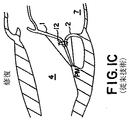
Alfieri 氏他は、低侵襲的修復機構の可能性を記載している。図1Cに示すように、小葉(1,2)の先端の間に縫糸(12)を配置することにより、小葉が互いに逸脱することが防止される。図1Dに示すように、これにより、縫糸(12)の両サイドに位置した2つの開口(14)を有した有効な弁が形成される。このようなオリフィスは、左心室内への血液流入を実質的に妨害することがない。 Alfieri et al. Describe the possibility of a minimally invasive repair mechanism. As shown in FIG. 1C, by disposing the sewing thread (12) between the tips of the leaflets (1, 2), the leaflets are prevented from deviating from each other. This forms an effective valve with two openings (14) located on both sides of the suture (12), as shown in FIG. 1D. Such an orifice does not substantially impede blood flow into the left ventricle.
この修復を低侵襲的に行うためのいくつかの手法が提案されている。特に、Grimes氏(米国特許第6,312,447号明細書)は、左心房内へと心房間中隔を横断してカテーテルを前進させ、カテーテルの先端に配置した真空吸引装置を使用して小葉の先端を把持し得ることを提案している。その後、例えばステープルや形状記憶リベットといったような固定器具を、小葉の先端内へと挿入し、エッジどうしを閉塞するという修復を行うことができる。 Several techniques have been proposed for performing this repair in a minimally invasive manner. In particular, Grimes (US Pat. No. 6,312,447) uses a vacuum suction device to advance the catheter across the interatrial septum into the left atrium and place it at the tip of the catheter. It has been proposed that the tip of the leaflet can be gripped. Thereafter, for example, a fixing device such as a staple or a shape memory rivet can be inserted into the tip of the leaflet to perform a repair by closing the edges.
小葉先端の真空吸引および/または縫合を使用した上記手法では、多くの共通の限界を免れない。まず最初にそして重要なことに、図2Aに示すように、そのような手法を受けるべき十分に大きなMRを有した患者においては、小葉(1,2)は、初期的には、互いに位置ズレを起こしている。この状況では、空間的に離間した位置(16,18)に位置している小葉の先端どうしを近接させて縫合して固定するためには、カテーテル(20)の先端に配置した単一のデバイス(22)の能力では限界があり、カテーテルの中心軸(11)に沿った単一の位置に、複数のデバイスを配置する必要がある。第2に、効果的であるためには、小葉の先端を把持するための真空吸引デバイスが、血液を急速に吸引しなければならない。血液が速やかに再注入されなければ、低血圧を引き起こすこととなる。第3に、図2Bに示すように、大動脈を通して付加的機構を挿入することによって、真空吸引デバイスに対して隣接していない小葉表面(3,4)を安定化しておかなければ、カテーテル(20)から突出しているリベットまたはステープル(15)は、小葉(1,2)を、カテーテル先端(22)から単に変位させるだけ(図2C)であり、小葉をうまく貫通することができない。第4に、小葉を把持する手法は、一般に、カテーテルに対して垂直な平面内で操作を行うものであり、ステープルや縫糸を挿入する小葉表面積が十分に大きくなく不安定である。 The above approach using vacuum suction and / or suturing of the leaflet tip is subject to many common limitations. First and importantly, as shown in FIG. 2A, in patients with sufficiently large MR to undergo such procedures, the leaflets (1,2) are initially misaligned with each other. Has caused. In this situation, a single device placed at the distal end of the catheter (20) is used to close and secure the tips of the leaflets located at spatially spaced positions (16, 18). The capability of (22) is limited and requires multiple devices to be placed at a single location along the central axis (11) of the catheter. Second, in order to be effective, a vacuum suction device for grasping the tip of the leaflet must rapidly aspirate blood. If blood is not reinfused promptly, it can cause hypotension. Third, as shown in FIG. 2B, the catheter (20) can be obtained unless the leaflet surface (3, 4) not adjacent to the vacuum suction device has been stabilized by inserting additional mechanisms through the aorta. The rivets or staples (15) projecting from) merely displace the leaflets (1, 2) from the catheter tip (22) (FIG. 2C) and cannot penetrate the leaflets well. Fourth, the method of grasping the leaflets is generally performed in a plane perpendicular to the catheter, and the leaflet surface area for inserting staples and sewing threads is not sufficiently large and unstable.
よって、要望されていることは、従来技術における上記制限や他の制限を克服し得るような、経皮的な僧帽弁(三尖弁)修復システムである。上記目的や他の目的のすべての実現し得るような単一デバイスが、大いに要望されている。
本発明は、心臓弁の逸脱に起因する僧帽弁閉鎖不全に関連した心臓病を治療するための、新規な装置、および、低侵襲的方法、を提供するものである。本発明においては、僧帽弁小葉どうしが位置合わせされているかどうかにかかわらず、僧帽弁小葉を個別的に把持して再位置決めすることができ、縫糸やステープルやリベット等を挿入し得るような、安定化された大きな表面積をもたらす。本発明による新規な経皮カテーテルや他の新規なデバイスを使用することにより、開胸や心臓切開を行う必要がない治療操作が可能とされる。しかしながら、本発明は、経皮的な手法に限定されるものではない。以下の説明においては、僧帽弁に対する応用に関するいくつかの好ましい実施態様を参照するけれども、これらは単なる例示に過ぎない。本発明が、三尖弁の小葉にも効果的に適用し得ることは、理解されるであろう。 The present invention provides a novel device and a minimally invasive method for treating heart disease associated with mitral regurgitation resulting from heart valve deviation. In the present invention, regardless of whether the mitral leaflets are aligned or not, the mitral leaflets can be individually gripped and repositioned so that sutures, staples, rivets, etc. can be inserted. Resulting in a large stabilized surface area. The use of the novel percutaneous catheter and other novel devices according to the present invention allows for therapeutic operations that do not require thoracotomy or cardiac incision. However, the present invention is not limited to a transcutaneous technique. In the following description, reference will be made to some preferred embodiments for application to a mitral valve, but these are merely exemplary. It will be appreciated that the present invention can also be applied effectively to tricuspid leaflets.
第1の見地においては、本発明は、僧帽弁を修復するためのデバイスおよびその使用方法を提供し、この場合、低侵襲的に搬送されるカテーテルアセンブリを具備し、このカテーテルアセンブリは、一対をなす操作可能な把持部材を備え、これら把持部材は、僧帽弁の近傍位置にまでカテーテルアセンブリを通して個別的に搬送可能とされている。把持部材は、カテーテルアセンブリから可逆的に径方向に延出可能とされ、これにより、2つのバルブ小葉を安定的に把持することができる。これにより、同様にカテーテルアセンブリを通して搬送される固定機構(例えば、ステープル、リベット、等)を使用することによって、それら小葉部分どうしを固定することができる。 In a first aspect, the present invention provides a device for repairing a mitral valve and a method of use thereof, comprising a minimally invasively delivered catheter assembly, the catheter assembly comprising a pair of catheter assemblies. The gripping members are individually transportable through the catheter assembly to a position proximate to the mitral valve. The gripping member can be reversibly extended radially from the catheter assembly, thereby stably gripping the two valve leaflets. This allows the leaflets to be secured together by using a securing mechanism (eg, staples, rivets, etc.) that is also transported through the catheter assembly.
一実施形態においては、カテーテルアセンブリは、単一のカテーテルを備え、このカテーテルは、順向きの前進に際しては実質的に直線状の形態とすることができる、あるいはこれに代えて、湾曲した先端部を有することができる。これにより、大動脈を経由した逆行的なアクセスを行うことができる。例えばニッケルチタン合金(例えば、ニチノール(登録商標))といったような形状記憶材料を使用することによって、カテーテルアセンブリの湾曲した先端部も含めて、本発明の様々な構成部材を形成することができる。固定機構および把持部材は、付加的には、形状記憶材料から形成される。 In one embodiment, the catheter assembly comprises a single catheter, which can be configured in a substantially straight configuration for forward advancement, or alternatively, a curved tip. Can have. Thereby, retrograde access via the aorta can be performed. By using a shape memory material such as a nickel titanium alloy (eg, Nitinol®), the various components of the present invention can be formed, including the curved tip of the catheter assembly. The securing mechanism and the gripping member are additionally formed from a shape memory material.
他の実施形態においては、カテーテルアセンブリは、互いにスライド可能に連結された一対をなす2つのカテーテルを具備し、各カテーテルは、僧帽弁領域にまで把持部材を搬送することができる。 In other embodiments, the catheter assembly comprises a pair of two catheters slidably connected to each other, each catheter capable of delivering a gripping member to the mitral valve region.
固定機構は、径方向に延出可能とされ、さらに、カテーテルアセンブリの少なくとも1つのサイドポートを通してカテーテルアセンブリに対して係合解除可能とされている。以下においては、小葉を貫通して挿入された後にカテーテルアセンブリから解除され得る固定機構について説明する。この結果、重要なことに、把持した小葉を、変位させることがない。 The securing mechanism is extendable in the radial direction and is further disengageable from the catheter assembly through at least one side port of the catheter assembly. In the following, a fixation mechanism is described that can be released from the catheter assembly after it has been inserted through the leaflet. As a result, importantly, the grasped leaflets are not displaced.
一実施形態においては、把持部材は、カテーテルアセンブリの先端部から延出され、各把持部材は、逆向きに変形した状態でカテーテルアセンブリの先端部から延出されることにより、弁小葉の心室側表面をクリップし得るようになっている。これに代えてあるいはこれに加えて、把持部材は、カテーテルアセンブリのサイドポートから延出可能とされ、弁小葉の心房側表面を把持し得るように操縦される。好ましい実施形態においては、2対をなす把持部材を使用し、これにより、後方小葉と前方小葉との両面が把持される。クリップ状構成の実施形態やジョーを備えた実施形態も含めて、把持部材の様々な実施形態について後述する。 In one embodiment, the gripping members are extended from the distal end of the catheter assembly, and each gripping member is extended from the distal end of the catheter assembly in a deformed direction, thereby providing a ventricular surface of the valve leaflet. Can be clipped. Alternatively or in addition, the grasping member can be extended from the side port of the catheter assembly and is steered to grasp the atrial surface of the valve leaflet. In a preferred embodiment, two pairs of gripping members are used, thereby gripping both the rear leaflet and the front leaflet. Various embodiments of the gripping member will be described later, including embodiments with clip-like configurations and embodiments with jaws.
ある種の実施形態においては、把持部材の操作は、把持対象をなす小葉に対して接触したことおよび/または近接したことを検出するセンサによって、トリガーされる。 In certain embodiments, manipulation of the gripping member is triggered by a sensor that detects contact and / or proximity to the leaflets that are to be gripped.
心臓弁の領域に関する外部からのまたは内部からの心臓撮影を使用することにより、把持部材の適切な配置や、手術の効果を、観測することができる。この撮影は、超音波の使用や、磁気共鳴の使用や、光ファイバの使用、によって代替することもできる。 By using external or internal cardiac imaging of the heart valve area, the proper placement of the gripping member and the effect of the surgery can be observed. This imaging can be replaced by using ultrasonic waves, using magnetic resonance, or using optical fibers.
本発明に関する理解をより明瞭なものとするため、添付図面を参照しながら、以下に、詳細な説明を行う。本発明の範囲は、特許請求の範囲に規定されている。 The following detailed description is made with reference to the accompanying drawings in order to make the understanding of the present invention clearer. The scope of the invention is defined in the claims.
本発明の利点は、添付図面を参照しつつ、本発明を何ら限定するものではなく単なる例示としての好ましい実施形態に関する以下の詳細な説明を読むことにより、明瞭となるであろう。 The advantages of the present invention will become apparent upon reading the following detailed description of the preferred embodiments, which are not intended to limit the invention in any way, but merely as examples, with reference to the accompanying drawings.
以下、本発明の好ましい実施形態について、複数の図面を参照して説明する。 Hereinafter, preferred embodiments of the present invention will be described with reference to a plurality of drawings.
以下においては、本発明のいくつかの実施形態について、僧帽弁の逸脱を例にとって説明する。本発明によるデバイスは、前方小葉と後方小葉とを個別的に把持し得ること、および、カテーテルアセンブリの軸に沿って互いに独立に並進移動させ得ること、を特徴としている。これにより、それら小葉どうしを固定する目的のために、小葉どうしを近接させることができる。しかしながら、当業者であれば理解されるように、本発明によるデバイスの使用は、僧帽弁に限定されるものではなく、三尖弁や他の任意の心臓弁に対しても適用することができる。 In the following, some embodiments of the invention will be described by taking mitral valve deviation as an example. The device according to the invention is characterized in that the anterior and posterior leaflets can be gripped individually and can be translated independently of each other along the axis of the catheter assembly. Thereby, the leaflets can be brought close together for the purpose of fixing the leaflets. However, as will be appreciated by those skilled in the art, the use of the device according to the present invention is not limited to mitral valves, but may be applied to tricuspid valves or any other heart valve. it can.
図3Aに示すように、本発明の一実施形態においては、経皮カテーテル(20)は、心房間中隔を介して、左心房(7)内へと挿入され、その後、僧帽弁小葉(前方小葉(1)だけが図示されている)どうしの間へと挿入され、さらに、左心室(4)内へと挿入され、再位置決め対象をなす隣接小葉(1)の近傍位置へと配置される。カテーテル(20)を通しては、少なくとも1つの小葉把持部材(24)を、カテーテル先端(22)から、可逆的に延出することができる。把持部材(24)は、形状記憶材料から構成されており、図3Bに示すように、カテーテル(20)の外表面(23)に向けて小葉(1)をクリップし得るにすなわち押圧し得るに適切であるような形状および寸法へと、予成形されている。把持部材(24)が先端(22)から押し出されたときには、把持部材(24)は、予成形状態となる。すなわち、図示のように、反転曲がり(25)を形成することができ、これにより、小葉(1)の心室側表面(3)上においてクリップ状構造を形成することができる。生体適合性形状記憶材料の製造は、当該技術分野においては周知であるので、ここでの説明は省略する。 As shown in FIG. 3A, in one embodiment of the present invention, a percutaneous catheter (20) is inserted into the left atrium (7) via the interatrial septum and then the mitral leaflet ( Inserted between each other (only the anterior leaflet (1) is shown), and further inserted into the left ventricle (4) and placed in the vicinity of the adjacent leaflet (1) to be repositioned. The Through the catheter (20), at least one leaflet gripping member (24) can be reversibly extended from the catheter tip (22). The gripping member (24) is made of a shape memory material and can clip or press the leaflet (1) towards the outer surface (23) of the catheter (20) as shown in FIG. 3B. Pre-formed into shapes and dimensions as appropriate. When the gripping member (24) is pushed out from the tip (22), the gripping member (24) is in a preformed state. That is, as shown, an inverted bend (25) can be formed, thereby forming a clip-like structure on the ventricular side surface (3) of the leaflet (1). The manufacture of biocompatible shape memory materials is well known in the art and will not be described here.
図3Cは、僧帽弁前方小葉を上から見た図であって、僧帽弁を示している。この場合には、デバイスは、小葉の両サイドに位置した腱索群(5)どうしの間のギャップ内において動作することに、注意されたい。好ましい実施形態においては、把持部材(24)は、好ましくは、2つのサイドアーム(26)を備えている。これらサイドアーム(26)は、V字形状でもってあるいは同様の形状でもって、カテーテル軸の両サイドに開いている。サイドアーム(26)どうしの開き具合は、把持部材に向いていない小葉の側から、それらサイドアームの間にステープルまたはリベット(30)を十分に挿入し得るものとされている。この構成は、小葉に対して単一のポイントにおいて当接する場合と比較して、大いなる安定性をもたらすとともに、プロセス内において小葉を変位させることなく把持部材のサイドアーム(26)の間にステープルまたはリベット(30)を挿入することを可能とする。この構成は、また、カテーテル(20)の外表面(23)に対しての比較的大きくかつ安定化した小葉表面積をもたらすとともに、ステープルまたはリベットの固定プロセス時における小葉の変位量を最小化する。代替可能な実施形態においては、カテーテル(20)上において補助的な真空吸引ポートを使用する。これにより、把持プロセスを補助することができる。小葉は、独立的に並進移動することができる。 FIG. 3C is a top view of the anterior mitral leaflet showing the mitral valve. Note that in this case the device operates in the gap between the chords (5) located on both sides of the leaflet. In a preferred embodiment, the gripping member (24) preferably comprises two side arms (26). These side arms (26) are V-shaped or similar in shape and open on both sides of the catheter shaft. The opening degree of the side arms (26) is such that staples or rivets (30) can be sufficiently inserted between the side arms from the side of the leaflets not facing the gripping member. This configuration provides greater stability compared to abutting the leaflets at a single point, and staples or grips between the side arms (26) of the gripping member without displacing the leaflets in the process. It is possible to insert a rivet (30). This configuration also provides a relatively large and stable leaflet surface area relative to the outer surface (23) of the catheter (20) and minimizes the amount of leaflet displacement during the staple or rivet fixation process. In an alternative embodiment, an auxiliary vacuum suction port is used on the catheter (20). Thereby, the gripping process can be assisted. The leaflets can translate independently.
図4Aに示すように、把持部材の代替可能な実施形態は、制御ロッド(34)を備えて構成されている。制御ロッド(34)は、保持ツール(32)が設けられている操縦可能な先端部(33)を有している。経皮的手術器具を操縦するための様々な機構は、当業者には公知であり、先端部(33)の操縦に際して使用することができる。これにより、保持ツール(32)を、把持している心房側表面(35)の一部に対して隣接配置することができる。各先端部(33)は、カテーテル(20)内のサイドポート(37)すなわちグルーブ内を通して、延出したり引っ込めたりすることができる。保持ツール(32)は、一実施形態においては、2つのペンチ状ジョー(36)(これらジョー(36)の2つの態様が、図4Bおよび図4Cに示されている)を有している。ジョー(36)は、小葉の心房側表面(35)を保持する。当業者であれば、現在利用可能であるような様々な他の機構を、ジョー(36)に代わる保持ツールとして使用可能であることは、理解されるであろう。そのような1つの代替例は、ペンチと組み合わせて真空吸引先端を使用することである。小葉とカテーテルとの当接を改良するための構成においては、双方の小葉を把持するのに必要なほどの大きな真空吸引は必要ではなく、ここでの真空吸引は、微細な位置決めおよび位置合わせのために使用される。 As shown in FIG. 4A, an alternative embodiment of the gripping member is configured with a control rod (34). The control rod (34) has a steerable tip (33) provided with a holding tool (32). Various mechanisms for maneuvering a percutaneous surgical instrument are known to those skilled in the art and can be used in maneuvering the tip (33). Thereby, the holding tool (32) can be disposed adjacent to a part of the grasped atrial surface (35). Each tip (33) can be extended or retracted through a side port (37) or groove in the catheter (20). The holding tool (32), in one embodiment, has two pliers-like jaws (36) (two aspects of these jaws (36) are shown in FIGS. 4B and 4C). The jaw (36) holds the atrial surface (35) of the leaflets. One skilled in the art will appreciate that a variety of other mechanisms, such as those currently available, can be used as a holding tool in place of the jaw (36). One such alternative is to use a vacuum suction tip in combination with pliers. The configuration for improving the contact between the leaflets and the catheter does not require as much vacuum suction as necessary to grip both leaflets, and vacuum suction here requires fine positioning and alignment. Used for.
他の実施形態(図示せず)においては、2つ以上の把持部材を使用して、小葉の心房側表面を把持する。複数の把持部材は、カテーテルから同様にして延出され、心房側表面の選択された軸方向長さ位置を把持することができる。例えば、2つの把持部材が、弁の一方側に配置され、他の2つの把持部材が、弁の他方側に配置される。これにより、小葉表面の正方形部分または矩形部分が安定化される。 In other embodiments (not shown), two or more grasping members are used to grasp the atrial surface of the leaflets. The plurality of grasping members extend similarly from the catheter and can grasp selected axial length positions of the atrial side surface. For example, two gripping members are disposed on one side of the valve and the other two gripping members are disposed on the other side of the valve. Thereby, the square part or rectangular part of the leaflet surface is stabilized.
上記において説明した実施形態においては、単一のカテーテル(20)を使用することによって、複数の把持部材を延出させて位置決めし、これにより、小葉の心室側表面または心房側表面に対して隣接配置させる。好ましい実施形態においては、個別の4つの把持部材を使用することにより、小葉の片面あたりにつき2つの把持部材を使用することによって、双方の小葉の両面が把持される。この構成は、固定ステップにわたって小葉どうしを近接させて安定化するように小葉を再位置決めするに際して、大いなるフレキシブルさをもたらす。 In the embodiment described above, a single catheter (20) is used to extend and position multiple gripping members, thereby adjacent to the ventricular or atrial surface of the leaflet. Arrange. In a preferred embodiment, by using four separate gripping members, both sides of both leaflets are gripped by using two gripping members per side of the leaflet. This arrangement provides great flexibility in repositioning the leaflets so that the leaflets are brought into close proximity and stabilized over the fixation step.
図3Dおよび図3Eに示す代替可能な実施形態においては、把持部材(24)は、互いに個別でありかつ互いに連結された2つのカテーテル(21,21’)を通して、互いに独立に搬送することができる。カテーテル(21,21’)は、例えばタングとグルーブとからなる構成によって、連結されている。よって、カテーテル(21,21’)は、共通平面内において互いに移動することができる。カテーテルどうしを並進移動させることにより、把持ステップ後の小葉(1,2)を所望に近接させることができる。カテーテルアセンブリ内の各カテーテル(21,21’)は、それぞれ開口を有している。これら開口どうしを位置合わせすることにより、チャネル(28)が形成される。小葉どうしが近接位置に再配置されたときには、このチャネル(28)を通して、ステープルまたはリベット(30)を延出させる。 In an alternative embodiment shown in FIGS. 3D and 3E, the gripping member (24) can be delivered independently of each other through two catheters (21, 21 ′) that are separate from each other and connected to each other. . The catheters (21, 21 ') are connected to each other by, for example, a tongue and a groove. Thus, the catheters (21, 21 ') can move relative to each other in a common plane. By moving the catheters in translation, the leaflets (1, 2) after the grasping step can be brought close to each other as desired. Each catheter (21, 21 ') in the catheter assembly has an opening. By aligning these openings, a channel (28) is formed. When the leaflets are repositioned in close proximity, the staple or rivet (30) is extended through this channel (28).
図5Aに示すように、小葉(1,2)が把持された近接配置されたときには、1つまたは複数のステープルまたはリベット(30)が、それら小葉を貫通して挿入される。一実施形態においては、ステープルまたはリベット(30)は、形状記憶材料から構成されており、カテーテル(20)の管腔内を移動し得るような寸法とされていて、カテーテルからの延出後には、急速に膨らむ。これにより、ステープルまたはリベット(30)が、カテーテルの側壁内のオリフィス(31)に到達した際には、挿入されて小葉どうしの固定が引き起こされる。ステープルまたはリベット(30)は、オリフィス(31)のところにまで、プランジャー(29)によってカテーテル(20)内を前進駆動される。その後、ステープルまたはリベット(30)は、突出するとともに、上記のようにして把持部材(24)によって既に安定的に把持された状態の双方の小葉を、穿孔する。形状記憶特性を有したステープルまたはリベットは、カテーテルの反対側において小葉の両側面上に突出し、その後、ステープルを形成するように曲がって戻ってくる。2つ以上のそのようなステープルまたはリベットを、それぞれ個別の向きでもって、同じサイトに挿入することができる。 As shown in FIG. 5A, when the leaflets (1, 2) are placed in close proximity, one or more staples or rivets (30) are inserted through the leaflets. In one embodiment, the staple or rivet (30) is constructed of a shape memory material and is dimensioned to move within the lumen of the catheter (20), after extension from the catheter. Swells rapidly. Thus, when the staple or rivet (30) reaches the orifice (31) in the side wall of the catheter, it is inserted to cause fixation of the leaflets. The staple or rivet (30) is driven forward through the catheter (20) by the plunger (29) to the orifice (31). Thereafter, the staple or rivet (30) protrudes and pierces both leaflets that have already been stably gripped by the gripping member (24) as described above. Staples or rivets with shape memory properties protrude on opposite sides of the leaflet on the opposite side of the catheter and then bend back to form staples. Two or more such staples or rivets can be inserted at the same site, each in a separate orientation.
図5Bに示すように、その後、カテーテルの側壁の退避可能ドア(40)を開放することができ、これにより、カテーテルとステープルとの係合を解除することができる。カテーテルは、他のサイトへと移動することができる。これにより、必要であれば、小葉どうしは、他の位置においても互いに固定することができる。これにより、修復が安定化される。カテーテルの係合が解除された後に、形状記憶デバイスは、有効なシールが形成されるまで、小葉どうしを継続して押圧することができる。 As shown in FIG. 5B, the retractable door (40) on the side wall of the catheter can then be opened, thereby disengaging the catheter and staple. The catheter can be moved to another site. Thus, if necessary, the leaflets can be fixed to each other at other positions. This stabilizes the repair. After the catheter is disengaged, the shape memory device can continue to press the leaflets until an effective seal is formed.
図5B〜図5Eは、2つ以上のサイトにおいて小葉どうしの固定を行う場合の操作手順を示している。これらの図においては、心臓弁は、前方小葉(1)を上側から見た場合に(図3Cと同じ向き)、互いに並置されている状態で示されている。カテーテル(20)は、心房経路から導入されたものとして図示されている。しかしながら、同じプロセスは、大動脈から逆行的にカテーテルを導入することによっても行うことができる。図5Bにおいては、ステープルまたはリベット(30)は、小葉内へのステープルまたはリベット(30)の押出を可能としているオリフィス(31)を通して、挿入されている。図5Cに示すように、カテーテルの側壁の一部(40)は、患者の体外からの制御手段によってカテーテルに対してワイヤや他の連結部材を駆動することにより、カテーテル管腔内へと退避されている。このステップにより、カテーテルの側壁に孔(41)が開口する。その後、カテーテルは、ステープルまたはリベットデバイスとの係合を解除し、カテーテル軸(37)に平行に並進移動する。図5Dは、小葉の一方側の近くの位置にまで移動してきたカテーテルを示している。図5Eは、穿孔オリフィス(31)を再形成するように再配置された退避可能なカテーテル壁部(40)を示しており、これにより、他のサイトにおいても小葉どうしを固定することができる。このことは、必要であれば、離間して閉鎖不全を起こした小葉どうしの正確な幾何形状に応じて、修復の効率を増大させる。この手法は、図3Dおよび図3Eに示すような互いに連結された複数のサブカテーテルを使用しても、各サブカテーテルの退避可能壁部を使用することにより、行うことができる。カテーテル側壁の退避可能部分は、カテーテルの両サイドに配置することができる。これにより、双方向に並進移動することができる。カテーテル手法の角度のわずかの角度調節を伴いつつ、1つのステープルが配置された後に、係合解除されたカテーテル(20)は、また、軸(37)に対して平行に並進移動することができ、左心室の中心軸に沿った2つ以上のサイトにおいて、付加的なステープルを挿入することができる。付加的なステープルは、初期的なカテーテルの軸に対して、平行なものとなる。 FIG. 5B to FIG. 5E show an operation procedure when the leaflets are fixed at two or more sites. In these figures, the heart valves are shown juxtaposed with each other when the anterior leaflet (1) is viewed from above (same orientation as in FIG. 3C). The catheter (20) is shown as being introduced from the atrial pathway. However, the same process can be performed by introducing the catheter retrogradely from the aorta. In FIG. 5B, the staple or rivet (30) has been inserted through an orifice (31) allowing the staple or rivet (30) to be pushed into the leaflet. As shown in FIG. 5C, a portion (40) of the side wall of the catheter is retracted into the catheter lumen by driving a wire or other connecting member relative to the catheter by control means from outside the patient's body. ing. This step opens a hole (41) in the side wall of the catheter. Thereafter, the catheter disengages from the staple or rivet device and translates parallel to the catheter axis (37). FIG. 5D shows the catheter having been moved to a position near one side of the leaflet. FIG. 5E shows the retractable catheter wall (40) repositioned to reshape the piercing orifice (31) so that the leaflets can be secured at other sites. This increases the efficiency of the repair, if necessary, depending on the exact geometry of the leaflets that are spaced apart and have failed. This technique can be performed using a plurality of sub-catheters connected to each other as shown in FIGS. 3D and 3E by using the retractable wall of each sub-catheter. The retractable portion of the catheter side wall can be located on both sides of the catheter. Thereby, it can translate in both directions. The disengaged catheter (20) can also translate parallel to the axis (37) after one staple is placed, with slight angular adjustment of the catheter approach angle. Additional staples can be inserted at two or more sites along the central axis of the left ventricle. The additional staples are parallel to the initial catheter axis.
図6Aおよび図6Bに示すように、代替可能な実施形態においては、カテーテル(20)を、大動脈を通して左心室(4)内へと逆行的に挿入する。カテーテルは、形状記憶材料を使用することによりあるいは当該技術分野において公知であるような他の操縦可能機構を使用することにより、曲がって戻り得るような形状とされている、あるいは、曲がって戻り得るように操縦可能とされている。本発明の利点は、大動脈経路と心房経路との双方の経路からの2つのカテーテルを使用することに代えて、新規な小葉把持部材に基づき、単一のカテーテルアセンブリを使用するだけで良いことである。小葉把持部材は、配置後には、小葉の先端に対して取り付けられる。把持部材(24)は、小葉の心室側表面上へとカテーテルから前向きに延出され、これにより、カテーテルとクリップとの間に小葉を挟み込む。このような前向き把持は、多数の機構によって得ることができる。例えば、把持部材(24)は、予成形された形状記憶材料から構成することができ、カテーテルのサイドポートから延出させた際には、小葉を押圧することができる。これに代えて、把持部材は、より剛直な部材から構成することができる。この場合、剛直な部材は、折曲ポイントを超えて延出された時点で、制御ロッド上へと折り曲げられてソックス状構成となり、カテーテルと折り曲げられた部分との間において小葉を押圧する。 As shown in FIGS. 6A and 6B, in an alternative embodiment, the catheter (20) is retrogradely inserted through the aorta and into the left ventricle (4). The catheter is shaped or can be bent back by using shape memory material or by using other steerable mechanisms as is known in the art. So that it can be steered. An advantage of the present invention is that instead of using two catheters from both the aortic and atrial pathways, a single catheter assembly need only be used based on the novel leaflet grasping member. is there. The leaflet gripping member is attached to the tip of the leaflet after placement. The gripping member (24) extends forward from the catheter onto the ventricular surface of the leaflet, thereby pinching the leaflet between the catheter and the clip. Such forward grip can be obtained by a number of mechanisms. For example, the gripping member (24) can be constructed from a pre-shaped shape memory material and can press the leaflets when extended from the side port of the catheter. Alternatively, the gripping member can be constructed from a more rigid member. In this case, when the rigid member is extended beyond the bending point, the rigid member is bent onto the control rod to form a sock-like structure, and presses the leaflets between the catheter and the bent portion.
図6Bに示すように、プロセス全体は、好ましくは、例えば心エコー検査といったような撮影技術を併用しつつ、実施される。このような撮影は、近赤外光による可視化(例えば、米国特許第6,178,346号明細書に開示されている。この文献の記載内容は、参考のため、その全体がここに組み込まれる)や、心臓内磁気共鳴撮影コイルや、経胸的リアルタイム3次元心エコー画像化、等を使用して、行うことができる。超音波撮影は、隣接した右心室の導出領域内に配置された個別の心臓内エコー(ICE)カテーテル(市販品)を使用することによって、あるいは、カテーテル(20)内に組み込まれていて左心室自体の内部に配置された超音波トランスデューサを使用することによって、胸部表面からあるいは食道からあるいは心臓内から、行うことができる。この構成により、撮影部材(50)をカテーテルを介して操作することができ、手術時に、心臓弁に関する高解像度の画像をもたらすことができ、また、僧帽弁小葉および閉鎖不全流を表示することもできる。3次元的超音波画像を得るために、複数の圧電性結晶からなる2次元マトリクスを使用することができる。あるいは、リニアフェーズドアレイを高速回転させ、これにより、3次元画像を得ることもできる。 As shown in FIG. 6B, the entire process is preferably performed in conjunction with imaging techniques such as echocardiography. Such imaging is disclosed in near-infrared light visualization (eg, US Pat. No. 6,178,346. The contents of this document are hereby incorporated by reference in their entirety. ), Intracardiac magnetic resonance imaging coils, transthoracic real-time three-dimensional echocardiography, and the like. Ultrasound imaging is performed by using a separate intracardiac echo (ICE) catheter (commercially available) placed in the exit region of the adjacent right ventricle, or incorporated into the catheter (20) and left ventricle. This can be done from the chest surface, from the esophagus, or from within the heart by using an ultrasonic transducer placed inside itself. With this configuration, the imaging member (50) can be manipulated through the catheter, can provide a high resolution image of the heart valve during surgery, and can display mitral leaflets and incompetent flow You can also. In order to obtain a three-dimensional ultrasonic image, a two-dimensional matrix composed of a plurality of piezoelectric crystals can be used. Alternatively, the three-dimensional image can be obtained by rotating the linear phased array at a high speed.
また、撮影に基づき、小葉に対してのカテーテルの当接を確認することができ、把持ステップをトリガーすることができる。撮影部材は、単なる圧電性結晶や、小葉の動きを検出する光コヒーレントデバイス、から構成することができる。収縮期に小葉がカテーテルに接近した場合には、デバイスは、出力ディスプレイデバイス上に手動でトリガー信号を確認用に出力する。確認後に、次なるトリガー信号が、把持部材を並進移動させるための機構に対して出力される。これにより、把持部材は、管腔内を迅速に進み、逆行的な形態をなす。これにより、捕捉がもたらされる。他の実施形態においては、小葉の捕捉は、この実施形態においては少なくとも部分的に強磁性材料から形成されている把持部材の延出された先端部が磁気ロッドおよびカテーテルに向けて急速に引き付けられる位置にまで、カテーテルの孔を通して磁気ロッドを迅速に前進させることにより、行われる。さらに他の実施形態においては、連結されたロッドを急速に前進させ、これにより、把持部材を小葉に対して反り返らせる。 Moreover, based on imaging | photography, the contact of the catheter with respect to a leaflet can be confirmed, and a grasping step can be triggered. The imaging member can be composed of a simple piezoelectric crystal or an optical coherent device that detects the movement of leaflets. If the leaflet approaches the catheter during systole, the device manually outputs a trigger signal for confirmation on the output display device. After confirmation, the next trigger signal is output to the mechanism for translating the gripping member. As a result, the grasping member rapidly proceeds in the lumen and takes a retrograde form. This provides capture. In other embodiments, the leaflet capture is rapidly attracted towards the magnetic rod and catheter with the extended tip of the gripping member, which in this embodiment is at least partially formed from a ferromagnetic material. This is done by rapidly advancing the magnetic rod through the catheter hole to position. In yet other embodiments, the connected rods are rapidly advanced, thereby causing the gripping member to warp against the leaflets.
図7Aおよび図7Bに示すように、カテーテルの延長部分(60)を、左心室の頂点(62)にまで延出させて安定化させることにより、双方の心臓導入経路(僧帽弁を経由する経路、および、大動脈を経由する経路)を使用することができる。延長部分(60)からは、頂点(62)に対しての接触を維持し得るような形状とされた湾曲した当接部材(64)が、延出されている。当接部材(64)は、形状記憶材料から形成することができ、カテーテルから延出されたときには、湾曲した接触構造を形成する。この場合、カテーテル(20)は、ワイヤに沿って並進移動することができ、把持部材(24,32)を、小葉の領域内において最適に位置決めすることができる。左心房を経由した中隔経由経路(図7A)の場合には、カテーテル安定化延長部分(60)は、固定カテーテル(20)に対して連続的である。一方、大動脈を逆行的に経由した逆行的経路(図7B)の場合には、固定用カテーテル(20)は、導入カテーテル(64)から突出しているとともに、小葉に向けて曲がっている。固定用カテーテル(20)は、直接的に、あるいは、閉塞的ゴムシールを有し得る案内アームを介して、導入カテーテル(64)のポートから突出している。導入カテーテル(64)は、カテーテルの先端から突出しているとともに心室頂点に対しての当接を維持し得る形状とされた湾曲した当接部材(64)によって、安定化されている。当接部材(64)は、これに代えて、弾性的な形状記憶材料から構成された複数の部材から形成することもできる。当接部材は、カテーテルから延出された時点で、湾曲した当接部材を形成し、心臓キャビティの内部の様々な部分に対して当接することができる。 As shown in FIGS. 7A and 7B, the catheter extension (60) extends to the apex (62) of the left ventricle and stabilizes, thereby allowing both cardioinduction pathways (via the mitral valve). Route and route through the aorta) can be used. Extending from the extension (60) is a curved abutment member (64) shaped to maintain contact with the apex (62). The abutment member (64) can be formed from a shape memory material and forms a curved contact structure when extended from the catheter. In this case, the catheter (20) can be translated along the wire and the gripping members (24, 32) can be optimally positioned within the region of the leaflets. In the case of a transseptal route via the left atrium (FIG. 7A), the catheter stabilization extension (60) is continuous with the fixed catheter (20). On the other hand, in the case of a retrograde path (FIG. 7B) retrogradely passing through the aorta, the fixation catheter (20) protrudes from the introduction catheter (64) and is bent toward the leaflet. The anchoring catheter (20) projects from the port of the introducer catheter (64) either directly or through a guide arm that may have an occlusive rubber seal. The introduction catheter (64) is stabilized by a curved contact member (64) that protrudes from the distal end of the catheter and is shaped to maintain contact with the apex of the ventricle. Alternatively, the contact member (64) can be formed of a plurality of members made of an elastic shape memory material. The abutment member, when extended from the catheter, forms a curved abutment member and can abut against various portions within the heart cavity.
言うまでもないが、上記において例示した安定化機構は、単なる例示に過ぎない。安定化機構は、ワイヤや形状記憶材料に限定されるものではなく、また、単一の延出可能な接触部分に限定されるものでもない。例えば、実施形態によっては、複数の安定化脚や入れ子式伸縮機構などを使用することによって、周縁回りの複数箇所において左心室内部に接触することができる。 Needless to say, the stabilization mechanism illustrated above is merely illustrative. The stabilization mechanism is not limited to wires or shape memory materials, nor is it limited to a single extendable contact portion. For example, in some embodiments, the left ventricle can be contacted at a plurality of locations around the periphery by using a plurality of stabilizing legs, a telescopic mechanism or the like.
本発明によるデバイスは、また、僧帽弁輪を経皮的に挿入することによって小葉の近似の補助を行う手術に関しても、有効である。そのようなデバイスは、冠状動脈洞や、環状部分のレベルにおいて僧帽弁を取り囲む静脈、の中へと挿入される(心臓の残部に対しての小葉の挿入)。環状サイズの低減は、また、小葉の近接を補助し、最適な修復を得ることができる。本発明によるデバイスを使用した技術の組合せは、僧帽弁の逸脱や萎縮性僧帽弁閉鎖不全の包括的修復に関しての、完全に経皮的な手法をもたらす。 The device according to the present invention is also useful for surgery where the mitral annulus is percutaneously inserted to assist in the approximation of the leaflets. Such a device is inserted into the coronary sinus and the vein surrounding the mitral valve at the level of the annulus (lobule insertion relative to the rest of the heart). The reduction in the annular size can also assist the proximity of the leaflets and obtain optimal repair. The combination of techniques using the device according to the present invention provides a completely percutaneous approach for comprehensive repair of mitral valve prolapse and atrophic mitral regurgitation.
本発明を使用することにより、また、膨出した心臓内における虚血性僧帽弁閉鎖不全を治療することができる。これにより、容積の過負荷を低減することができ、心臓麻痺を防止することができる。そのような患者における多数のより深刻な閉鎖不全障害は、本発明によるデバイスによって修復し得る小葉部分どうしの不具合である。本発明は、経皮的環状リング低減といったような修復対象をなす小葉にかかる張力を低減させるための手法と組み合わせて、また、心室のサイズを低減するための手法と組み合わせて、使用することができる。本発明を使用することにより、互いに異常を起こしていて逸脱しておりそのため閉鎖不全を起こしているような後方小葉の中の任意の2つを並置することができる。 By using the present invention, ischemic mitral regurgitation can also be treated in the swelled heart. Thereby, the overload of a volume can be reduced and heart failure can be prevented. A number of more serious insufficiency disorders in such patients are defects in the leaflet parts that can be repaired by the device according to the invention. The present invention can be used in combination with a technique for reducing the tension applied to a leaflet to be repaired, such as percutaneous annular ring reduction, and in combination with a technique for reducing the size of a ventricle. it can. By using the present invention, any two of the posterior leaflets that are abnormal and deviating from each other and thus causing an insufficiency can be juxtaposed.
上記においては、ある種の好ましい実施形態に関して説明したけれども、上記説明は、例示のためのものに過ぎない。当業者には、本発明の精神の範囲を逸脱することなく、様々な変形や他の実施態様とし得ることが自明であろう。上記例示における細部は、本発明の原理を逸脱することなく、変形することができる。そのような修正や変形も、また、本発明の精神および範囲内に属することが意図されている。 Although described above with respect to certain preferred embodiments, the above description is for illustrative purposes only. It will be apparent to those skilled in the art that various modifications and other embodiments can be made without departing from the spirit of the invention. Details in the above examples can be modified without departing from the principles of the invention. Such modifications and variations are also intended to fall within the spirit and scope of the present invention.
1 前方小葉
2 小葉
4 左心室
7 左心房
20 経皮カテーテル
21 カテーテル
21’ カテーテル
24 把持部材
26 サイドアーム
28 チャネル
30 ステープルまたはリベット
31 オリフィス
34 制御ロッド
35 心房側表面
36 ジョー
37 サイドポート
40 退避可能ドア
64 当接部材
1
Claims (21)
患者の脈管系を通して遠隔的に心臓内の心臓弁に隣接した位置にまで搬送され得るよう構成されたカテーテルアセンブリと;
前記カテーテルアセンブリ内を通って互いに独立に並進移動可能とされた少なくとも2つの操作可能な把持部材であるとともに、前記カテーテルアセンブリから先端・基端方向にかつ横向きに延出可能なものとされ、これにより、2つの弁小葉のそれぞれの再配置部分を把持して近接状態とし得るような、少なくとも2つの操作可能な把持部材と;
前記カテーテルアセンブリを通って並進移動可能とされ、さらに、前記2つの弁小葉の前記近接状態とされた部分どうしを固定し得るものとされた、固定機構と;
を具備し、
前記固定機構が、横向きに延出可能とされ、さらに、前記カテーテルアセンブリの少なくとも1つのオリフィスを通して前記カテーテルアセンブリに対して係合解除可能とされ、
前記各把持部材が、延出の向きとは逆向きにすなわち基端向きに変形した状態で、すなわち反転曲がりを形成した状態で、前記カテーテルアセンブリの先端部から延出され、これにより、弁小葉の心室側表面をクリップし得るようになっていることを特徴とするデバイス。A device for heart valve repair,
A catheter assembly configured to be remotely delivered through the patient's vasculature to a location in the heart adjacent to the heart valve;
And at least two operable gripping members that can be translated independently of each other through the catheter assembly, and can extend from the catheter assembly in the distal and proximal directions and laterally. At least two manipulable gripping members such that the respective repositioned portions of the two valve leaflets can be gripped and brought into proximity;
A securing mechanism that is translatable through the catheter assembly and that is capable of securing the adjacent portions of the two valve leaflets;
Comprising
The securing mechanism is extendable laterally and is disengageable from the catheter assembly through at least one orifice of the catheter assembly;
Wherein each gripping member is in a state the extension unloading orientation deformed in the opposite direction ie proximal direction, i.e. in a state of forming a curved inverted, extend from the previous end of the catheter assembly, by which the valve A device characterized by being capable of clipping the ventricular side surface of a leaflet.
前記カテーテルアセンブリが、湾曲した先端部を有した単一のカテーテルを備え、
これにより、弁に対しての大動脈からの逆行的なアクセスが可能とされていることを特徴とするデバイス。The device of claim 1, wherein
The catheter assembly comprises a single catheter having a curved tip;
Thereby, the retrograde access from the aorta to the valve is enabled.
前記先端部の少なくとも一部が、形状記憶材料から構成されていることを特徴とするデバイス。The device of claim 2, wherein
A device characterized in that at least a part of the tip is made of a shape memory material.
前記カテーテルアセンブリが、互いにスライド可能に連結された一対をなす2つのカテーテルから構成され、
各カテーテルには、1つの前記把持部材が配置され、
各カテーテルが、少なくとも1つのオリフィスを備え、
前記固定機構が、前記オリフィスを通して延出可能とされ、さらに、前記カテーテルアセンブリに対して係合解除可能とされていることを特徴とするデバイス。The device of claim 1, wherein
The catheter assembly comprises a pair of two catheters slidably connected to each other;
Each catheter is provided with one said gripping member,
Each catheter comprises at least one orifice ;
A device wherein the locking mechanism is extendable through the orifice and further disengaged from the catheter assembly.
前記固定機構が、ステープルまたはリベットを備え、
前記ステープルまたはリベットが、小葉を変位させることなく、小葉のうちの、前記把持部材によって把持された部分を貫通して挿入可能とされていることを特徴とするデバイス。The device of claim 1, wherein
The fixing mechanism comprises staples or rivets;
The device is characterized in that the staple or rivet can be inserted through a portion of the leaflet gripped by the gripping member without displacing the leaflet.
前記固定機構の少なくとも一部が、形状記憶材料から構成されていることを特徴とするデバイス。The device of claim 1, wherein
At least a part of the fixing mechanism is made of a shape memory material.
前記カテーテルアセンブリが、前記少なくとも1つのオリフィスの近傍に、退避可能部分を備え、
この退避可能部分が、退避状態においては、ノッチを形成し、
このノッチを使用して、前記固定機構が、前記カテーテルアセンブリに対して係合解除可能とされていることを特徴とするデバイス。The device of claim 1, wherein
The catheter assembly comprises a retractable portion in the vicinity of the at least one orifice;
This retractable part forms a notch in the retracted state,
A device wherein the notch is used to disengage the locking mechanism from the catheter assembly.
前記カテーテルアセンブリを通って互いに独立に並進移動可能とされた一対をなす操縦可能な把持部材を具備し、
前記各把持部材が、前記カテーテルアセンブリの互いに反対側に位置した少なくとも2つのオリフィスの一方から横向きに延出可能とされ、
前記各把持部材の延出が、前記各把持部材の変形を調節可能な態様で行われ、これにより、弁小葉の心房側表面を把持し得るようになっていることを特徴とするデバイス。The device of claim 1, wherein
A pair of steerable gripping members that are translatable independently of each other through the catheter assembly;
Each gripping member can extend laterally from one of at least two orifices located on opposite sides of the catheter assembly;
The device is characterized in that the extension of each gripping member is performed in such a manner that the deformation of each gripping member can be adjusted, whereby the atrial side surface of the valve leaflet can be gripped.
前記各把持部材が、前記カテーテルアセンブリの互いに反対側に位置した少なくとも2つのオリフィスの一方から延出可能とされ、
前記各把持部材の延出が、前記各把持部材を変形させつつ行われ、これにより、弁小葉の心室側表面を把持し得るようになっていることを特徴とするデバイス。The device of claim 1, wherein
Each gripping member can extend from one of at least two orifices located on opposite sides of the catheter assembly;
The device is characterized in that the extension of each gripping member is performed while the gripping members are deformed, whereby the ventricle side surface of the valve leaflet can be gripped.
前記各把持部材が、前記カテーテルアセンブリの互いに反対側に位置した少なくとも2つのオリフィスの一方から延出可能とされ、
前記各把持部材の延出が、前記各把持部材の変形を調節可能な態様で行われ、これにより、弁小葉の心房側表面を把持し得るようになっていることを特徴とするデバイス。The device of claim 1, wherein
Each gripping member can extend from one of at least two orifices located on opposite sides of the catheter assembly;
The device is characterized in that the extension of each gripping member is performed in such a manner that the deformation of each gripping member can be adjusted, whereby the atrial side surface of the valve leaflet can be gripped.
前記把持部材の各先端部には、一対をなす操作可能なジョーが配置されていることを特徴とするデバイス。The device of claim 10, wherein
A device characterized in that a pair of operable jaws is disposed at each distal end of the gripping member.
前記把持部材の各先端部には、真空吸引アセンブリが配置されていることを特徴とするデバイス。The device of claim 10, wherein
A device in which a vacuum suction assembly is disposed at each tip of the gripping member.
前記把持部材の少なくとも一部が、形状記憶材料から形成されていることを特徴とするデバイス。The device of claim 1, wherein
A device characterized in that at least a part of the gripping member is made of a shape memory material.
さらに、前記カテーテルアセンブリを前記心臓弁に向けて搬送するための導入カテーテルを具備していることを特徴とするデバイス。The device of claim 1, wherein
The device further comprising an introducer catheter for delivering the catheter assembly toward the heart valve.
前記導入カテーテルが、前記カテーテルアセンブリを前記心臓弁の近傍位置にまで操作可能とするための案内アームを備えていることを特徴とするデバイス。The device of claim 14, wherein
A device wherein the introducer catheter comprises a guide arm for allowing the catheter assembly to be manipulated to a position proximate to the heart valve.
前記導入カテーテルが、左心室内において前記導入カテーテルの位置を一時的に安定化させるための安定化手段を備えていることを特徴とするデバイス。The device of claim 14, wherein
A device characterized in that the introducer catheter comprises stabilizing means for temporarily stabilizing the position of the introducer catheter in the left ventricle.
前記安定化手段が、1つまたは複数の接触部材を有し、
この接触部材が、前記導入カテーテルから先端・基端方向に延出可能とされ、
前記接触部材が、心臓キャビティの内表面に対して1つまたは複数のポイントにおいて接触可能とされていることを特徴とするデバイス。The device of claim 16, wherein
The stabilizing means comprises one or more contact members;
This contact member can be extended from the introduction catheter in the distal and proximal directions,
A device wherein the contact member is capable of contacting the inner surface of the heart cavity at one or more points.
前記1つまたは複数の接触部材が、形状記憶材料から形成されていることを特徴とするデバイス。The device of claim 17, wherein
The device wherein the one or more contact members are formed from a shape memory material.
さらに、前記心臓弁の近傍領域を撮影し得るような向きとされた撮影デバイスを具備していることを特徴とするデバイス。The device of claim 1, wherein
The device further comprises an imaging device oriented to image an area near the heart valve.
さらに、保持トリガー機構を具備し、
この保持トリガー機構が、前記把持部材に対しての弁小葉の位置を検出するための1つまたは複数のセンサを備え、
前記把持部材が、弁小葉が前記把持部材から所定距離以内に位置したことが検出されたことに応答して延出されることを特徴とするデバイス。The device of claim 1, wherein
Furthermore, it has a holding trigger mechanism,
The holding trigger mechanism comprises one or more sensors for detecting the position of the valve leaflets relative to the gripping member;
The device, wherein the gripping member is extended in response to detecting that the valve leaflet is located within a predetermined distance from the gripping member.
患者の脈管系を通して遠隔的に心臓内の心臓弁に隣接した位置にまで搬送され得るよう構成されたカテーテルアセンブリと;
前記カテーテルアセンブリ内を通って互いに独立に並進移動可能とされた少なくとも2つの操作可能な把持部材であるとともに、前記カテーテルアセンブリから先端・基端方向にかつ横向きに延出可能なものとされ、これにより、2つの弁小葉のそれぞれの再配置部分を把持して近接状態とし得るような、少なくとも2つの操作可能な把持部材と;
前記カテーテルアセンブリを通って並進移動可能とされ、さらに、前記2つの弁小葉の前記近接状態とされた部分どうしを固定し得るものとされた、固定機構と;
を具備し、
前記固定機構が、横向きに延出可能とされ、さらに、前記カテーテルアセンブリの少なくとも1つのオリフィスを通して前記カテーテルアセンブリに対して係合解除可能とされ、
前記カテーテルアセンブリが、互いにスライド可能に連結された一対をなす2つのカテーテルから構成され、
各カテーテルには、1つの前記把持部材が配置され、
各カテーテルが、少なくとも1つのオリフィスを備え、
前記固定機構が、前記オリフィスを通して延出可能とされ、さらに、前記カテーテルアセンブリに対して係合解除可能とされていることを特徴とするデバイス。A device for heart valve repair,
A catheter assembly configured to be remotely delivered through the patient's vasculature to a location in the heart adjacent to the heart valve;
And at least two operable gripping members that can be translated independently of each other through the catheter assembly, and can extend from the catheter assembly in the distal and proximal directions and laterally. At least two manipulable gripping members such that the respective repositioned portions of the two valve leaflets can be gripped and brought into proximity;
A securing mechanism that is translatable through the catheter assembly and that is capable of securing the adjacent portions of the two valve leaflets;
Comprising
The securing mechanism is extendable laterally and is disengageable from the catheter assembly through at least one orifice of the catheter assembly;
The catheter assembly comprises a pair of two catheters slidably connected to each other;
Each catheter is provided with one said gripping member,
Each catheter comprises at least one orifice ;
A device wherein the locking mechanism is extendable through the orifice and further disengaged from the catheter assembly.
Applications Claiming Priority (3)
| Application Number | Priority Date | Filing Date | Title |
|---|---|---|---|
| US40307302P | 2002-08-13 | 2002-08-13 | |
| US60/403,073 | 2002-08-13 | ||
| PCT/US2003/025521 WO2004014282A2 (en) | 2002-08-13 | 2003-08-13 | Cardiac devices and methods for percutaneous repair of atrioventricular valves |
Publications (2)
| Publication Number | Publication Date |
|---|---|
| JP2006500977A JP2006500977A (en) | 2006-01-12 |
| JP4929428B2 true JP4929428B2 (en) | 2012-05-09 |
Family
ID=31715930
Family Applications (1)
| Application Number | Title | Priority Date | Filing Date |
|---|---|---|---|
| JP2004528141A Expired - Fee Related JP4929428B2 (en) | 2002-08-13 | 2003-08-13 | Cardiac device and method for percutaneous repair of atrioventricular valve |
Country Status (8)
| Country | Link |
|---|---|
| US (1) | US7559936B2 (en) |
| EP (2) | EP2319427A2 (en) |
| JP (1) | JP4929428B2 (en) |
| AT (1) | ATE384479T1 (en) |
| AU (1) | AU2003262683A1 (en) |
| CA (1) | CA2496007C (en) |
| DE (1) | DE60318861T2 (en) |
| WO (1) | WO2004014282A2 (en) |
Families Citing this family (214)
| Publication number | Priority date | Publication date | Assignee | Title |
|---|---|---|---|---|
| US6050936A (en) | 1997-01-02 | 2000-04-18 | Myocor, Inc. | Heart wall tension reduction apparatus |
| US6269819B1 (en) * | 1997-06-27 | 2001-08-07 | The Trustees Of Columbia University In The City Of New York | Method and apparatus for circulatory valve repair |
| FR2768324B1 (en) | 1997-09-12 | 1999-12-10 | Jacques Seguin | SURGICAL INSTRUMENT FOR PERCUTANEOUSLY FIXING TWO AREAS OF SOFT TISSUE, NORMALLY MUTUALLY REMOTE, TO ONE ANOTHER |
| US6332893B1 (en) * | 1997-12-17 | 2001-12-25 | Myocor, Inc. | Valve to myocardium tension members device and method |
| US6260552B1 (en) | 1998-07-29 | 2001-07-17 | Myocor, Inc. | Transventricular implant tools and devices |
| US7811296B2 (en) | 1999-04-09 | 2010-10-12 | Evalve, Inc. | Fixation devices for variation in engagement of tissue |
| US20040044350A1 (en) | 1999-04-09 | 2004-03-04 | Evalve, Inc. | Steerable access sheath and methods of use |
| US10327743B2 (en) * | 1999-04-09 | 2019-06-25 | Evalve, Inc. | Device and methods for endoscopic annuloplasty |
| US8216256B2 (en) | 1999-04-09 | 2012-07-10 | Evalve, Inc. | Detachment mechanism for implantable fixation devices |
| US6752813B2 (en) | 1999-04-09 | 2004-06-22 | Evalve, Inc. | Methods and devices for capturing and fixing leaflets in valve repair |
| US7666204B2 (en) | 1999-04-09 | 2010-02-23 | Evalve, Inc. | Multi-catheter steerable guiding system and methods of use |
| WO2000060995A2 (en) | 1999-04-09 | 2000-10-19 | Evalve, Inc. | Methods and apparatus for cardiac valve repair |
| EP1113497A3 (en) * | 1999-12-29 | 2006-01-25 | Texas Instruments Incorporated | Semiconductor package with conductor impedance selected during assembly |
| US6723038B1 (en) | 2000-10-06 | 2004-04-20 | Myocor, Inc. | Methods and devices for improving mitral valve function |
| US6602286B1 (en) | 2000-10-26 | 2003-08-05 | Ernst Peter Strecker | Implantable valve system |
| US6575971B2 (en) | 2001-11-15 | 2003-06-10 | Quantum Cor, Inc. | Cardiac valve leaflet stapler device and methods thereof |
| US20030120341A1 (en) * | 2001-12-21 | 2003-06-26 | Hani Shennib | Devices and methods of repairing cardiac valves |
| US6764510B2 (en) | 2002-01-09 | 2004-07-20 | Myocor, Inc. | Devices and methods for heart valve treatment |
| US7048754B2 (en) | 2002-03-01 | 2006-05-23 | Evalve, Inc. | Suture fasteners and methods of use |
| US6752828B2 (en) | 2002-04-03 | 2004-06-22 | Scimed Life Systems, Inc. | Artificial valve |
| WO2004002364A2 (en) | 2002-06-27 | 2004-01-08 | Levine Robert A | Ventricular remodeling for artioventricular valve regurgitation |
| CA2494758C (en) | 2002-08-01 | 2013-03-19 | The General Hospital Corporation | Cardiac devices and methods for minimally invasive repair of ischemic mitral regurgitation |
| US7087064B1 (en) | 2002-10-15 | 2006-08-08 | Advanced Cardiovascular Systems, Inc. | Apparatuses and methods for heart valve repair |
| US7112219B2 (en) | 2002-11-12 | 2006-09-26 | Myocor, Inc. | Devices and methods for heart valve treatment |
| US7485143B2 (en) | 2002-11-15 | 2009-02-03 | Abbott Cardiovascular Systems Inc. | Apparatuses and methods for heart valve repair |
| US7981152B1 (en) | 2004-12-10 | 2011-07-19 | Advanced Cardiovascular Systems, Inc. | Vascular delivery system for accessing and delivering devices into coronary sinus and other vascular sites |
| US7335213B1 (en) | 2002-11-15 | 2008-02-26 | Abbott Cardiovascular Systems Inc. | Apparatus and methods for heart valve repair |
| US9149602B2 (en) | 2005-04-22 | 2015-10-06 | Advanced Cardiovascular Systems, Inc. | Dual needle delivery system |
| US8187324B2 (en) | 2002-11-15 | 2012-05-29 | Advanced Cardiovascular Systems, Inc. | Telescoping apparatus for delivering and adjusting a medical device in a vessel |
| US6945957B2 (en) | 2002-12-30 | 2005-09-20 | Scimed Life Systems, Inc. | Valve treatment catheter and methods |
| US7257450B2 (en) * | 2003-02-13 | 2007-08-14 | Coaptus Medical Corporation | Systems and methods for securing cardiovascular tissue |
| US10646229B2 (en) | 2003-05-19 | 2020-05-12 | Evalve, Inc. | Fixation devices, systems and methods for engaging tissue |
| US7998112B2 (en) | 2003-09-30 | 2011-08-16 | Abbott Cardiovascular Systems Inc. | Deflectable catheter assembly and method of making same |
| US7854761B2 (en) | 2003-12-19 | 2010-12-21 | Boston Scientific Scimed, Inc. | Methods for venous valve replacement with a catheter |
| US8128681B2 (en) | 2003-12-19 | 2012-03-06 | Boston Scientific Scimed, Inc. | Venous valve apparatus, system, and method |
| EP1734903B2 (en) | 2004-03-11 | 2022-01-19 | Percutaneous Cardiovascular Solutions Pty Limited | Percutaneous heart valve prosthesis |
| US20050240202A1 (en) * | 2004-04-21 | 2005-10-27 | Hani Shennib | Devices and methods of repairing cardiac valves |
| EP3143944B1 (en) | 2004-05-14 | 2018-08-01 | Evalve, Inc. | Locking mechanisms for fixation devices |
| US7566343B2 (en) | 2004-09-02 | 2009-07-28 | Boston Scientific Scimed, Inc. | Cardiac valve, system, and method |
| JP2008513060A (en) * | 2004-09-14 | 2008-05-01 | エドワーズ ライフサイエンシーズ アーゲー | Device and method for treatment of heart valve regurgitation |
| CA2581852C (en) | 2004-09-27 | 2012-11-13 | Evalve, Inc. | Methods and devices for tissue grasping and assessment |
| US8052592B2 (en) | 2005-09-27 | 2011-11-08 | Evalve, Inc. | Methods and devices for tissue grasping and assessment |
| CN101495049B (en) * | 2005-01-21 | 2010-12-15 | 梅约医学教育与研究基金会 | Thorascopic heart valve repair method and apparatus |
| US20060173490A1 (en) | 2005-02-01 | 2006-08-03 | Boston Scientific Scimed, Inc. | Filter system and method |
| US7854755B2 (en) | 2005-02-01 | 2010-12-21 | Boston Scientific Scimed, Inc. | Vascular catheter, system, and method |
| US7878966B2 (en) | 2005-02-04 | 2011-02-01 | Boston Scientific Scimed, Inc. | Ventricular assist and support device |
| US7780722B2 (en) | 2005-02-07 | 2010-08-24 | Boston Scientific Scimed, Inc. | Venous valve apparatus, system, and method |
| WO2006086434A1 (en) | 2005-02-07 | 2006-08-17 | Evalve, Inc. | Methods, systems and devices for cardiac valve repair |
| WO2011034628A1 (en) | 2005-02-07 | 2011-03-24 | Evalve, Inc. | Methods, systems and devices for cardiac valve repair |
| US7670368B2 (en) | 2005-02-07 | 2010-03-02 | Boston Scientific Scimed, Inc. | Venous valve apparatus, system, and method |
| US7867274B2 (en) | 2005-02-23 | 2011-01-11 | Boston Scientific Scimed, Inc. | Valve apparatus, system and method |
| WO2006097931A2 (en) | 2005-03-17 | 2006-09-21 | Valtech Cardio, Ltd. | Mitral valve treatment techniques |
| US7722666B2 (en) | 2005-04-15 | 2010-05-25 | Boston Scientific Scimed, Inc. | Valve apparatus, system and method |
| SE531468C2 (en) * | 2005-04-21 | 2009-04-14 | Edwards Lifesciences Ag | An apparatus for controlling blood flow |
| US8012198B2 (en) | 2005-06-10 | 2011-09-06 | Boston Scientific Scimed, Inc. | Venous valve, system, and method |
| US8502681B2 (en) | 2005-06-20 | 2013-08-06 | Biovigil, Llc | Hand cleanliness |
| US7616122B2 (en) | 2005-06-20 | 2009-11-10 | Biovigil, Llc | Hand cleanliness |
| US8303510B2 (en) * | 2005-07-01 | 2012-11-06 | Scimed Life Systems, Inc. | Medical imaging device having a forward looking flow detector |
| US8951285B2 (en) | 2005-07-05 | 2015-02-10 | Mitralign, Inc. | Tissue anchor, anchoring system and methods of using the same |
| CN100445488C (en) | 2005-08-01 | 2008-12-24 | 邱则有 | Hollow member for cast-in-situ concrete moulding |
| US7569071B2 (en) | 2005-09-21 | 2009-08-04 | Boston Scientific Scimed, Inc. | Venous valve, system, and method with sinus pocket |
| US7799038B2 (en) | 2006-01-20 | 2010-09-21 | Boston Scientific Scimed, Inc. | Translumenal apparatus, system, and method |
| US7648527B2 (en) * | 2006-03-01 | 2010-01-19 | Cook Incorporated | Methods of reducing retrograde flow |
| GB2437921B (en) * | 2006-05-10 | 2011-08-03 | Francis Wells | Heart valve repair |
| US8932348B2 (en) | 2006-05-18 | 2015-01-13 | Edwards Lifesciences Corporation | Device and method for improving heart valve function |
| US20070282429A1 (en) * | 2006-06-01 | 2007-12-06 | Hauser David L | Prosthetic insert for improving heart valve function |
| US11259924B2 (en) | 2006-12-05 | 2022-03-01 | Valtech Cardio Ltd. | Implantation of repair devices in the heart |
| US9883943B2 (en) | 2006-12-05 | 2018-02-06 | Valtech Cardio, Ltd. | Implantation of repair devices in the heart |
| WO2010004546A1 (en) | 2008-06-16 | 2010-01-14 | Valtech Cardio, Ltd. | Annuloplasty devices and methods of delivery therefor |
| US9192471B2 (en) | 2007-01-08 | 2015-11-24 | Millipede, Inc. | Device for translumenal reshaping of a mitral valve annulus |
| US8133270B2 (en) | 2007-01-08 | 2012-03-13 | California Institute Of Technology | In-situ formation of a valve |
| US7967853B2 (en) | 2007-02-05 | 2011-06-28 | Boston Scientific Scimed, Inc. | Percutaneous valve, system and method |
| US11660190B2 (en) | 2007-03-13 | 2023-05-30 | Edwards Lifesciences Corporation | Tissue anchors, systems and methods, and devices |
| US8828079B2 (en) | 2007-07-26 | 2014-09-09 | Boston Scientific Scimed, Inc. | Circulatory valve, system and method |
| AU2008311754B2 (en) | 2007-10-18 | 2012-10-04 | Neochord Inc. | Minimially invasive repair of a valve leaflet in a beating heart |
| US8512362B2 (en) * | 2007-11-05 | 2013-08-20 | Usgi Medical Inc. | Endoscopic ligation |
| WO2009072114A2 (en) * | 2007-12-02 | 2009-06-11 | Mor Research Applications Ltd. | Access to the left atrium and reduction of mitral valve leaflet mobility |
| US7892276B2 (en) | 2007-12-21 | 2011-02-22 | Boston Scientific Scimed, Inc. | Valve with delayed leaflet deployment |
| US8382829B1 (en) | 2008-03-10 | 2013-02-26 | Mitralign, Inc. | Method to reduce mitral regurgitation by cinching the commissure of the mitral valve |
| DE102008013858A1 (en) * | 2008-03-12 | 2009-09-24 | Siemens Aktiengesellschaft | Catheter device and associated medical examination and treatment device |
| US20090276040A1 (en) | 2008-05-01 | 2009-11-05 | Edwards Lifesciences Corporation | Device and method for replacing mitral valve |
| EP2358297B1 (en) | 2008-11-21 | 2019-09-11 | Percutaneous Cardiovascular Solutions Pty Limited | Heart valve prosthesis |
| US8926696B2 (en) | 2008-12-22 | 2015-01-06 | Valtech Cardio, Ltd. | Adjustable annuloplasty devices and adjustment mechanisms therefor |
| US8545553B2 (en) | 2009-05-04 | 2013-10-01 | Valtech Cardio, Ltd. | Over-wire rotation tool |
| US8241351B2 (en) | 2008-12-22 | 2012-08-14 | Valtech Cardio, Ltd. | Adjustable partial annuloplasty ring and mechanism therefor |
| US10517719B2 (en) | 2008-12-22 | 2019-12-31 | Valtech Cardio, Ltd. | Implantation of repair devices in the heart |
| US9011530B2 (en) | 2008-12-22 | 2015-04-21 | Valtech Cardio, Ltd. | Partially-adjustable annuloplasty structure |
| US8715342B2 (en) | 2009-05-07 | 2014-05-06 | Valtech Cardio, Ltd. | Annuloplasty ring with intra-ring anchoring |
| US8147542B2 (en) | 2008-12-22 | 2012-04-03 | Valtech Cardio, Ltd. | Adjustable repair chords and spool mechanism therefor |
| US8353956B2 (en) | 2009-02-17 | 2013-01-15 | Valtech Cardio, Ltd. | Actively-engageable movement-restriction mechanism for use with an annuloplasty structure |
| US9968452B2 (en) | 2009-05-04 | 2018-05-15 | Valtech Cardio, Ltd. | Annuloplasty ring delivery cathethers |
| EP2633821B1 (en) | 2009-09-15 | 2016-04-06 | Evalve, Inc. | Device for cardiac valve repair |
| US20110077733A1 (en) * | 2009-09-25 | 2011-03-31 | Edwards Lifesciences Corporation | Leaflet contacting apparatus and method |
| US10098737B2 (en) | 2009-10-29 | 2018-10-16 | Valtech Cardio, Ltd. | Tissue anchor for annuloplasty device |
| US9011520B2 (en) | 2009-10-29 | 2015-04-21 | Valtech Cardio, Ltd. | Tissue anchor for annuloplasty device |
| US9180007B2 (en) | 2009-10-29 | 2015-11-10 | Valtech Cardio, Ltd. | Apparatus and method for guide-wire based advancement of an adjustable implant |
| US8201828B2 (en) * | 2009-11-12 | 2012-06-19 | Scott Curry | Wagering game based on Bayes' theorem |
| WO2011067770A1 (en) | 2009-12-02 | 2011-06-09 | Valtech Cardio, Ltd. | Delivery tool for implantation of spool assembly coupled to a helical anchor |
| US8449599B2 (en) | 2009-12-04 | 2013-05-28 | Edwards Lifesciences Corporation | Prosthetic valve for replacing mitral valve |
| US8870950B2 (en) | 2009-12-08 | 2014-10-28 | Mitral Tech Ltd. | Rotation-based anchoring of an implant |
| EP2590595B1 (en) | 2010-07-09 | 2015-08-26 | Highlife SAS | Transcatheter atrio-ventricular valve prosthesis |
| US11653910B2 (en) | 2010-07-21 | 2023-05-23 | Cardiovalve Ltd. | Helical anchor implantation |
| US20120053680A1 (en) | 2010-08-24 | 2012-03-01 | Bolling Steven F | Reconfiguring Heart Features |
| US20120095348A1 (en) * | 2010-10-19 | 2012-04-19 | Sonavation, Inc. | Three Dimensional Imaging Intra Cardiac Echocardiography (ICE) Catheter |
| CN103347464B (en) | 2010-12-29 | 2016-02-03 | 尼奥绰德有限公司 | The replaceable system of beating heart valve leaflet is repaired by Wicresoft |
| US8845717B2 (en) | 2011-01-28 | 2014-09-30 | Middle Park Medical, Inc. | Coaptation enhancement implant, system, and method |
| US8888843B2 (en) | 2011-01-28 | 2014-11-18 | Middle Peak Medical, Inc. | Device, system, and method for transcatheter treatment of valve regurgitation |
| CA2837206C (en) | 2011-06-01 | 2019-09-24 | John Zentgraf | Minimally invasive repair of heart valve leaflets |
| US9918840B2 (en) | 2011-06-23 | 2018-03-20 | Valtech Cardio, Ltd. | Closed band for percutaneous annuloplasty |
| US10792152B2 (en) | 2011-06-23 | 2020-10-06 | Valtech Cardio, Ltd. | Closed band for percutaneous annuloplasty |
| US9668859B2 (en) | 2011-08-05 | 2017-06-06 | California Institute Of Technology | Percutaneous heart valve delivery systems |
| US8945177B2 (en) | 2011-09-13 | 2015-02-03 | Abbott Cardiovascular Systems Inc. | Gripper pusher mechanism for tissue apposition systems |
| US8858623B2 (en) | 2011-11-04 | 2014-10-14 | Valtech Cardio, Ltd. | Implant having multiple rotational assemblies |
| EP3656434B1 (en) | 2011-11-08 | 2021-10-20 | Valtech Cardio, Ltd. | Controlled steering functionality for implant-delivery tool |
| WO2013120082A1 (en) | 2012-02-10 | 2013-08-15 | Kassab Ghassan S | Methods and uses of biological tissues for various stent and other medical applications |
| US10849755B2 (en) | 2012-09-14 | 2020-12-01 | Boston Scientific Scimed, Inc. | Mitral valve inversion prostheses |
| US10543088B2 (en) | 2012-09-14 | 2020-01-28 | Boston Scientific Scimed, Inc. | Mitral valve inversion prostheses |
| US9216018B2 (en) | 2012-09-29 | 2015-12-22 | Mitralign, Inc. | Plication lock delivery system and method of use thereof |
| US10376266B2 (en) | 2012-10-23 | 2019-08-13 | Valtech Cardio, Ltd. | Percutaneous tissue anchor techniques |
| EP2911594B1 (en) | 2012-10-23 | 2018-12-05 | Valtech Cardio, Ltd. | Controlled steering functionality for implant-delivery tool |
| WO2014087402A1 (en) | 2012-12-06 | 2014-06-12 | Valtech Cardio, Ltd. | Techniques for guide-wire based advancement of a tool |
| ES2934670T3 (en) | 2013-01-24 | 2023-02-23 | Cardiovalve Ltd | Ventricularly Anchored Prosthetic Valves |
| EP2953580A2 (en) | 2013-02-11 | 2015-12-16 | Cook Medical Technologies LLC | Expandable support frame and medical device |
| US9724084B2 (en) | 2013-02-26 | 2017-08-08 | Mitralign, Inc. | Devices and methods for percutaneous tricuspid valve repair |
| US10449333B2 (en) | 2013-03-14 | 2019-10-22 | Valtech Cardio, Ltd. | Guidewire feeder |
| WO2014144247A1 (en) | 2013-03-15 | 2014-09-18 | Arash Kheradvar | Handle mechanism and functionality for repositioning and retrieval of transcatheter heart valves |
| EP2968847B1 (en) | 2013-03-15 | 2023-03-08 | Edwards Lifesciences Corporation | Translation catheter systems |
| US10070857B2 (en) | 2013-08-31 | 2018-09-11 | Mitralign, Inc. | Devices and methods for locating and implanting tissue anchors at mitral valve commissure |
| US10299793B2 (en) | 2013-10-23 | 2019-05-28 | Valtech Cardio, Ltd. | Anchor magazine |
| US10166098B2 (en) | 2013-10-25 | 2019-01-01 | Middle Peak Medical, Inc. | Systems and methods for transcatheter treatment of valve regurgitation |
| US9610162B2 (en) | 2013-12-26 | 2017-04-04 | Valtech Cardio, Ltd. | Implantation of flexible implant |
| US9572666B2 (en) | 2014-03-17 | 2017-02-21 | Evalve, Inc. | Mitral valve fixation device removal devices and methods |
| US10390943B2 (en) | 2014-03-17 | 2019-08-27 | Evalve, Inc. | Double orifice device for transcatheter mitral valve replacement |
| EP3157469B1 (en) | 2014-06-18 | 2021-12-15 | Polares Medical Inc. | Mitral valve implants for the treatment of valvular regurgitation |
| CA2958065C (en) | 2014-06-24 | 2023-10-31 | Middle Peak Medical, Inc. | Systems and methods for anchoring an implant |
| US9180005B1 (en) | 2014-07-17 | 2015-11-10 | Millipede, Inc. | Adjustable endolumenal mitral valve ring |
| EP3922213A1 (en) | 2014-10-14 | 2021-12-15 | Valtech Cardio, Ltd. | Leaflet-restraining techniques |
| CN111437068B (en) | 2014-12-04 | 2023-01-17 | 爱德华兹生命科学公司 | Percutaneous clamp for repairing heart valve |
| US10188392B2 (en) | 2014-12-19 | 2019-01-29 | Abbott Cardiovascular Systems, Inc. | Grasping for tissue repair |
| WO2016110760A1 (en) | 2015-01-05 | 2016-07-14 | Strait Access Technologies Holdings (Pty) Ltd | Heart valve leaflet capture device |
| EP3242609B2 (en) * | 2015-01-05 | 2023-08-09 | Strait Access Technologies Holdings (PTY) LTD | Heart valve leaflet capture device |
| CN110141399B (en) | 2015-02-05 | 2021-07-27 | 卡迪尔维尔福股份有限公司 | Prosthetic valve with axially sliding frame |
| CN107530166B (en) | 2015-02-13 | 2020-01-31 | 魅尔皮德股份有限公司 | Valve replacement using a rotating anchor |
| US20160256269A1 (en) | 2015-03-05 | 2016-09-08 | Mitralign, Inc. | Devices for treating paravalvular leakage and methods use thereof |
| US20160287383A1 (en) * | 2015-04-01 | 2016-10-06 | Edwards Lifesciences Corporation | Heart valve repair devices |
| US10524912B2 (en) | 2015-04-02 | 2020-01-07 | Abbott Cardiovascular Systems, Inc. | Tissue fixation devices and methods |
| CN114515173A (en) | 2015-04-30 | 2022-05-20 | 瓦尔泰克卡迪欧有限公司 | Valvuloplasty techniques |
| CN110433010A (en) | 2015-05-14 | 2019-11-12 | 爱德华兹生命科学公司 | Heart valve sealing device and its delivery apparatus |
| EP3539509B1 (en) | 2015-06-01 | 2021-07-07 | Edwards Lifesciences Corporation | Cardiac valve repair devices configured for percutaneous delivery |
| US10376673B2 (en) | 2015-06-19 | 2019-08-13 | Evalve, Inc. | Catheter guiding system and methods |
| US10238494B2 (en) | 2015-06-29 | 2019-03-26 | Evalve, Inc. | Self-aligning radiopaque ring |
| US10667815B2 (en) | 2015-07-21 | 2020-06-02 | Evalve, Inc. | Tissue grasping devices and related methods |
| US10413408B2 (en) | 2015-08-06 | 2019-09-17 | Evalve, Inc. | Delivery catheter systems, methods, and devices |
| US10335275B2 (en) | 2015-09-29 | 2019-07-02 | Millipede, Inc. | Methods for delivery of heart valve devices using intravascular ultrasound imaging |
| WO2017059406A1 (en) | 2015-10-01 | 2017-04-06 | Neochord, Inc. | Ringless web for repair of heart valves |
| US10238495B2 (en) | 2015-10-09 | 2019-03-26 | Evalve, Inc. | Delivery catheter handle and methods of use |
| US9592121B1 (en) | 2015-11-06 | 2017-03-14 | Middle Peak Medical, Inc. | Device, system, and method for transcatheter treatment of valvular regurgitation |
| JP6892446B2 (en) | 2015-11-17 | 2021-06-23 | ボストン サイエンティフィック サイムド,インコーポレイテッドBoston Scientific Scimed,Inc. | Implantable equipment and delivery system to reshape the heart valve annulus |
| EP3397207A4 (en) | 2015-12-30 | 2019-09-11 | Mitralign, Inc. | System and method for reducing tricuspid regurgitation |
| US10751182B2 (en) | 2015-12-30 | 2020-08-25 | Edwards Lifesciences Corporation | System and method for reshaping right heart |
| US10531866B2 (en) | 2016-02-16 | 2020-01-14 | Cardiovalve Ltd. | Techniques for providing a replacement valve and transseptal communication |
| US10799675B2 (en) | 2016-03-21 | 2020-10-13 | Edwards Lifesciences Corporation | Cam controlled multi-direction steerable handles |
| US10702274B2 (en) | 2016-05-26 | 2020-07-07 | Edwards Lifesciences Corporation | Method and system for closing left atrial appendage |
| US10736632B2 (en) | 2016-07-06 | 2020-08-11 | Evalve, Inc. | Methods and devices for valve clip excision |
| GB201611910D0 (en) | 2016-07-08 | 2016-08-24 | Valtech Cardio Ltd | Adjustable annuloplasty device with alternating peaks and troughs |
| CA3031187A1 (en) | 2016-08-10 | 2018-02-15 | Cardiovalve Ltd. | Prosthetic valve with concentric frames |
| WO2018058157A1 (en) * | 2016-09-26 | 2018-03-29 | Williams Mervyn Alexander | An accessory for assisting with the repair of a mitral valve |
| US11071564B2 (en) | 2016-10-05 | 2021-07-27 | Evalve, Inc. | Cardiac valve cutting device |
| US10653862B2 (en) | 2016-11-07 | 2020-05-19 | Edwards Lifesciences Corporation | Apparatus for the introduction and manipulation of multiple telescoping catheters |
| US10363138B2 (en) | 2016-11-09 | 2019-07-30 | Evalve, Inc. | Devices for adjusting the curvature of cardiac valve structures |
| US10398553B2 (en) | 2016-11-11 | 2019-09-03 | Evalve, Inc. | Opposing disk device for grasping cardiac valve tissue |
| US10426616B2 (en) | 2016-11-17 | 2019-10-01 | Evalve, Inc. | Cardiac implant delivery system |
| US10779837B2 (en) | 2016-12-08 | 2020-09-22 | Evalve, Inc. | Adjustable arm device for grasping tissues |
| US10314586B2 (en) | 2016-12-13 | 2019-06-11 | Evalve, Inc. | Rotatable device and method for fixing tricuspid valve tissue |
| US10905554B2 (en) | 2017-01-05 | 2021-02-02 | Edwards Lifesciences Corporation | Heart valve coaptation device |
| WO2018148584A1 (en) | 2017-02-10 | 2018-08-16 | Millipede, Inc. | Implantable device and delivery system for reshaping a heart valve annulus |
| US10653524B2 (en) | 2017-03-13 | 2020-05-19 | Polares Medical Inc. | Device, system, and method for transcatheter treatment of valvular regurgitation |
| EP3595587A4 (en) | 2017-03-13 | 2020-11-11 | Polares Medical Inc. | Device, system, and method for transcatheter treatment of valvular regurgitation |
| US10478303B2 (en) | 2017-03-13 | 2019-11-19 | Polares Medical Inc. | Device, system, and method for transcatheter treatment of valvular regurgitation |
| US10213306B2 (en) | 2017-03-31 | 2019-02-26 | Neochord, Inc. | Minimally invasive heart valve repair in a beating heart |
| US11045627B2 (en) | 2017-04-18 | 2021-06-29 | Edwards Lifesciences Corporation | Catheter system with linear actuation control mechanism |
| US11224511B2 (en) | 2017-04-18 | 2022-01-18 | Edwards Lifesciences Corporation | Heart valve sealing devices and delivery devices therefor |
| BR112019021267A2 (en) | 2017-04-18 | 2020-05-19 | Edwards Lifesciences Corp | heart valve sealing devices and release devices |
| US10799312B2 (en) | 2017-04-28 | 2020-10-13 | Edwards Lifesciences Corporation | Medical device stabilizing apparatus and method of use |
| US11065119B2 (en) | 2017-05-12 | 2021-07-20 | Evalve, Inc. | Long arm valve repair clip |
| US10842619B2 (en) | 2017-05-12 | 2020-11-24 | Edwards Lifesciences Corporation | Prosthetic heart valve docking assembly |
| US11069220B2 (en) | 2017-07-10 | 2021-07-20 | Biovigil Hygiene Technologies, Llc | Hand cleanliness monitoring |
| US11051940B2 (en) | 2017-09-07 | 2021-07-06 | Edwards Lifesciences Corporation | Prosthetic spacer device for heart valve |
| US11110251B2 (en) | 2017-09-19 | 2021-09-07 | Edwards Lifesciences Corporation | Multi-direction steerable handles for steering catheters |
| US10835221B2 (en) | 2017-11-02 | 2020-11-17 | Valtech Cardio, Ltd. | Implant-cinching devices and systems |
| US11135062B2 (en) | 2017-11-20 | 2021-10-05 | Valtech Cardio Ltd. | Cinching of dilated heart muscle |
| CN109953778B (en) * | 2017-12-26 | 2022-02-22 | 先健科技(深圳)有限公司 | Clamping device and system for fixing tissue |
| US10245144B1 (en) | 2018-01-09 | 2019-04-02 | Edwards Lifesciences Corporation | Native valve repair devices and procedures |
| AU2019207613A1 (en) | 2018-01-09 | 2020-07-02 | Edwards Lifesciences Corporation | Native valve repair devices and procedures |
| US10231837B1 (en) | 2018-01-09 | 2019-03-19 | Edwards Lifesciences Corporation | Native valve repair devices and procedures |
| US10111751B1 (en) | 2018-01-09 | 2018-10-30 | Edwards Lifesciences Corporation | Native valve repair devices and procedures |
| CN111655199B (en) | 2018-01-22 | 2023-09-26 | 爱德华兹生命科学公司 | Heart-shaped maintenance anchor |
| WO2019145947A1 (en) | 2018-01-24 | 2019-08-01 | Valtech Cardio, Ltd. | Contraction of an annuloplasty structure |
| EP3743014B1 (en) | 2018-01-26 | 2023-07-19 | Edwards Lifesciences Innovation (Israel) Ltd. | Techniques for facilitating heart valve tethering and chord replacement |
| US11285003B2 (en) | 2018-03-20 | 2022-03-29 | Medtronic Vascular, Inc. | Prolapse prevention device and methods of use thereof |
| US11026791B2 (en) | 2018-03-20 | 2021-06-08 | Medtronic Vascular, Inc. | Flexible canopy valve repair systems and methods of use |
| AU2019238344B2 (en) | 2018-03-23 | 2021-06-24 | Neochord, Inc. | Device for suture attachment for minimally invasive heart valve repair |
| US11389297B2 (en) | 2018-04-12 | 2022-07-19 | Edwards Lifesciences Corporation | Mitral valve spacer device |
| US11207181B2 (en) | 2018-04-18 | 2021-12-28 | Edwards Lifesciences Corporation | Heart valve sealing devices and delivery devices therefor |
| US11173030B2 (en) | 2018-05-09 | 2021-11-16 | Neochord, Inc. | Suture length adjustment for minimally invasive heart valve repair |
| US11253360B2 (en) | 2018-05-09 | 2022-02-22 | Neochord, Inc. | Low profile tissue anchor for minimally invasive heart valve repair |
| AU2019301967A1 (en) | 2018-07-12 | 2021-01-21 | Edwards Lifesciences Innovation (Israel) Ltd. | Annuloplasty systems and locking tools therefor |
| WO2020051583A1 (en) | 2018-09-07 | 2020-03-12 | Neochord, Inc. | Device for suture attachment for minimally invasive heart valve repair |
| US10945844B2 (en) | 2018-10-10 | 2021-03-16 | Edwards Lifesciences Corporation | Heart valve sealing devices and delivery devices therefor |
| EP3923867B1 (en) | 2019-02-14 | 2023-08-30 | Edwards Lifesciences Corporation | Heart valve sealing devices and delivery devices therefor |
| EP3955855A4 (en) | 2019-04-16 | 2023-01-25 | NeoChord, Inc. | Transverse helical cardiac anchor for minimally invasive heart valve repair |
| WO2021084407A1 (en) | 2019-10-29 | 2021-05-06 | Valtech Cardio, Ltd. | Annuloplasty and tissue anchor technologies |
| US11464634B2 (en) | 2020-12-16 | 2022-10-11 | Polares Medical Inc. | Device, system, and method for transcatheter treatment of valvular regurgitation with secondary anchors |
| US11759321B2 (en) | 2021-06-25 | 2023-09-19 | Polares Medical Inc. | Device, system, and method for transcatheter treatment of valvular regurgitation |
Citations (4)
| Publication number | Priority date | Publication date | Assignee | Title |
|---|---|---|---|---|
| WO2000060995A2 (en) * | 1999-04-09 | 2000-10-19 | Evalve, Inc. | Methods and apparatus for cardiac valve repair |
| WO2001028432A1 (en) * | 1999-10-21 | 2001-04-26 | Edwards Lifesciences Corporation | Minimally invasive mitral valve repair method and apparatus |
| JP2001517464A (en) * | 1997-09-12 | 2001-10-09 | エバルブ, インコーポレイテッド | Surgical instrument for fixing soft tissue |
| WO2002034167A2 (en) * | 2000-10-23 | 2002-05-02 | St. Jude Medical, Inc. | Mitral and tricuspid valve repair |
Family Cites Families (21)
| Publication number | Priority date | Publication date | Assignee | Title |
|---|---|---|---|---|
| DE3504292C1 (en) * | 1985-02-08 | 1986-07-24 | Richard Wolf Gmbh, 7134 Knittlingen | Instrument for endoscopic interventions, especially for percutaneous gallstone removal or gallbladder surgery |
| US5395367A (en) * | 1992-07-29 | 1995-03-07 | Wilk; Peter J. | Laparoscopic instrument with bendable shaft and removable actuator |
| CA2220689A1 (en) | 1995-05-10 | 1996-11-14 | Cardiogenesis Corporation | System for treating or diagnosing heart tissue |
| US5716399A (en) | 1995-10-06 | 1998-02-10 | Cardiomend Llc | Methods of heart valve repair |
| US6183411B1 (en) | 1998-09-21 | 2001-02-06 | Myocor, Inc. | External stress reduction device and method |
| US5876373A (en) * | 1997-04-04 | 1999-03-02 | Eclipse Surgical Technologies, Inc. | Steerable catheter |
| US6269819B1 (en) | 1997-06-27 | 2001-08-07 | The Trustees Of Columbia University In The City Of New York | Method and apparatus for circulatory valve repair |
| US6165183A (en) * | 1998-07-15 | 2000-12-26 | St. Jude Medical, Inc. | Mitral and tricuspid valve repair |
| US6352503B1 (en) * | 1998-07-17 | 2002-03-05 | Olympus Optical Co., Ltd. | Endoscopic surgery apparatus |
| US6080175A (en) | 1998-07-29 | 2000-06-27 | Corvascular, Inc. | Surgical cutting instrument and method of use |
| US6355030B1 (en) | 1998-09-25 | 2002-03-12 | Cardiothoracic Systems, Inc. | Instruments and methods employing thermal energy for the repair and replacement of cardiac valves |
| US6178346B1 (en) | 1998-10-23 | 2001-01-23 | David C. Amundson | Infrared endoscopic imaging in a liquid with suspended particles: method and apparatus |
| US6432039B1 (en) | 1998-12-21 | 2002-08-13 | Corset, Inc. | Methods and apparatus for reinforcement of the heart ventricles |
| US6752813B2 (en) | 1999-04-09 | 2004-06-22 | Evalve, Inc. | Methods and devices for capturing and fixing leaflets in valve repair |
| US6312447B1 (en) | 1999-10-13 | 2001-11-06 | The General Hospital Corporation | Devices and methods for percutaneous mitral valve repair |
| US6840246B2 (en) | 2000-06-20 | 2005-01-11 | University Of Maryland, Baltimore | Apparatuses and methods for performing minimally invasive diagnostic and surgical procedures inside of a beating heart |
| US6575971B2 (en) | 2001-11-15 | 2003-06-10 | Quantum Cor, Inc. | Cardiac valve leaflet stapler device and methods thereof |
| US20030120341A1 (en) | 2001-12-21 | 2003-06-26 | Hani Shennib | Devices and methods of repairing cardiac valves |
| US6540666B1 (en) | 2002-01-08 | 2003-04-01 | Heart Care Associates, Llc | Adaptive device for supporting cardiac function during diastolic dysfunction and method therefor |
| WO2004002364A2 (en) | 2002-06-27 | 2004-01-08 | Levine Robert A | Ventricular remodeling for artioventricular valve regurgitation |
| CA2494758C (en) | 2002-08-01 | 2013-03-19 | The General Hospital Corporation | Cardiac devices and methods for minimally invasive repair of ischemic mitral regurgitation |
-
2003
- 2003-08-13 EP EP10185283A patent/EP2319427A2/en not_active Withdrawn
- 2003-08-13 DE DE60318861T patent/DE60318861T2/en not_active Expired - Lifetime
- 2003-08-13 CA CA2496007A patent/CA2496007C/en not_active Expired - Lifetime
- 2003-08-13 AT AT03785293T patent/ATE384479T1/en not_active IP Right Cessation
- 2003-08-13 JP JP2004528141A patent/JP4929428B2/en not_active Expired - Fee Related
- 2003-08-13 AU AU2003262683A patent/AU2003262683A1/en not_active Abandoned
- 2003-08-13 EP EP03785293A patent/EP1534146B1/en not_active Expired - Lifetime
- 2003-08-13 WO PCT/US2003/025521 patent/WO2004014282A2/en active IP Right Grant
- 2003-08-13 US US10/640,974 patent/US7559936B2/en active Active
Patent Citations (4)
| Publication number | Priority date | Publication date | Assignee | Title |
|---|---|---|---|---|
| JP2001517464A (en) * | 1997-09-12 | 2001-10-09 | エバルブ, インコーポレイテッド | Surgical instrument for fixing soft tissue |
| WO2000060995A2 (en) * | 1999-04-09 | 2000-10-19 | Evalve, Inc. | Methods and apparatus for cardiac valve repair |
| WO2001028432A1 (en) * | 1999-10-21 | 2001-04-26 | Edwards Lifesciences Corporation | Minimally invasive mitral valve repair method and apparatus |
| WO2002034167A2 (en) * | 2000-10-23 | 2002-05-02 | St. Jude Medical, Inc. | Mitral and tricuspid valve repair |
Also Published As
| Publication number | Publication date |
|---|---|
| WO2004014282A3 (en) | 2004-07-08 |
| EP1534146A2 (en) | 2005-06-01 |
| WO2004014282A2 (en) | 2004-02-19 |
| CA2496007C (en) | 2013-02-05 |
| JP2006500977A (en) | 2006-01-12 |
| ATE384479T1 (en) | 2008-02-15 |
| EP2319427A2 (en) | 2011-05-11 |
| DE60318861T2 (en) | 2009-01-08 |
| WO2004014282A9 (en) | 2004-06-03 |
| EP1534146B1 (en) | 2008-01-23 |
| DE60318861D1 (en) | 2008-03-13 |
| US20040122448A1 (en) | 2004-06-24 |
| AU2003262683A1 (en) | 2004-02-25 |
| CA2496007A1 (en) | 2005-02-11 |
| EP1534146A4 (en) | 2005-11-09 |
| AU2003262683A8 (en) | 2004-02-25 |
| US7559936B2 (en) | 2009-07-14 |
Similar Documents
| Publication | Publication Date | Title |
|---|---|---|
| JP4929428B2 (en) | Cardiac device and method for percutaneous repair of atrioventricular valve | |
| US10499905B2 (en) | Methods and apparatus for atrioventricular valve repair | |
| US11730591B2 (en) | Method and apparatus for percutaneous delivery and deployment of a cardiovascular prosthesis | |
| US20210030534A1 (en) | Method and apparatus for percutaneous delivery and deployment of a cardiac valve prosthesis | |
| RU2708222C2 (en) | Heart valve leaflet capture device | |
| JP4808964B2 (en) | Heart device and method for minimally invasive repair of ischemic mitral regurgitation | |
| EP2465568B1 (en) | Steerable guide catheter having preformed curved shape | |
| EP0930845B1 (en) | Apparatus for circulatory valve repair | |
| US6312447B1 (en) | Devices and methods for percutaneous mitral valve repair | |
| JP4657456B2 (en) | Method and apparatus for heart valve repair | |
| US20050267493A1 (en) | Method and system for tissue repair using dual catheters | |
| US20100298930A1 (en) | Access to the left atrium and reduction of mitral valve leaflet mobility | |
| US20230190468A1 (en) | Leaflet positioning and fixing clip and narrow-environment orientation system thereof | |
| JP7389489B2 (en) | Negative pressure gripping systems, methods and tools | |
| EP1917919B1 (en) | Cardiac devices for percutaneous repair of atrioventricular valves | |
| CN113288516A (en) | Anchoring clamp and valve closing instrument using same | |
| CN117357307A (en) | Valve repair device and valve repair system |
Legal Events
| Date | Code | Title | Description |
|---|---|---|---|
| A621 | Written request for application examination |
Free format text: JAPANESE INTERMEDIATE CODE: A621 Effective date: 20060519 |
|
| A131 | Notification of reasons for refusal |
Free format text: JAPANESE INTERMEDIATE CODE: A131 Effective date: 20090519 |
|
| A601 | Written request for extension of time |
Free format text: JAPANESE INTERMEDIATE CODE: A601 Effective date: 20090819 |
|
| A602 | Written permission of extension of time |
Free format text: JAPANESE INTERMEDIATE CODE: A602 Effective date: 20090826 |
|
| A521 | Request for written amendment filed |
Free format text: JAPANESE INTERMEDIATE CODE: A523 Effective date: 20091119 |
|
| A131 | Notification of reasons for refusal |
Free format text: JAPANESE INTERMEDIATE CODE: A131 Effective date: 20100209 |
|
| A601 | Written request for extension of time |
Free format text: JAPANESE INTERMEDIATE CODE: A601 Effective date: 20100510 |
|
| A602 | Written permission of extension of time |
Free format text: JAPANESE INTERMEDIATE CODE: A602 Effective date: 20100517 |
|
| A521 | Request for written amendment filed |
Free format text: JAPANESE INTERMEDIATE CODE: A523 Effective date: 20100809 |
|
| A02 | Decision of refusal |
Free format text: JAPANESE INTERMEDIATE CODE: A02 Effective date: 20100921 |
|
| A521 | Request for written amendment filed |
Free format text: JAPANESE INTERMEDIATE CODE: A523 Effective date: 20110121 |
|
| A911 | Transfer to examiner for re-examination before appeal (zenchi) |
Free format text: JAPANESE INTERMEDIATE CODE: A911 Effective date: 20110131 |
|
| A131 | Notification of reasons for refusal |
Free format text: JAPANESE INTERMEDIATE CODE: A131 Effective date: 20110308 |
|
| A601 | Written request for extension of time |
Free format text: JAPANESE INTERMEDIATE CODE: A601 Effective date: 20110608 |
|
| A602 | Written permission of extension of time |
Free format text: JAPANESE INTERMEDIATE CODE: A602 Effective date: 20110615 |
|
| A521 | Request for written amendment filed |
Free format text: JAPANESE INTERMEDIATE CODE: A523 Effective date: 20110901 |
|
| A01 | Written decision to grant a patent or to grant a registration (utility model) |
Free format text: JAPANESE INTERMEDIATE CODE: A01 Effective date: 20110927 |
|
| A711 | Notification of change in applicant |
Free format text: JAPANESE INTERMEDIATE CODE: A711 Effective date: 20111021 |
|
| A61 | First payment of annual fees (during grant procedure) |
Free format text: JAPANESE INTERMEDIATE CODE: A61 Effective date: 20111027 |
|
| A521 | Request for written amendment filed |
Free format text: JAPANESE INTERMEDIATE CODE: A821 Effective date: 20111021 |
|
| A521 | Request for written amendment filed |
Free format text: JAPANESE INTERMEDIATE CODE: A523 Effective date: 20111215 |
|
| R150 | Certificate of patent or registration of utility model |
Free format text: JAPANESE INTERMEDIATE CODE: R150 |
|
| FPAY | Renewal fee payment (event date is renewal date of database) |
Free format text: PAYMENT UNTIL: 20150224 Year of fee payment: 3 |
|
| LAPS | Cancellation because of no payment of annual fees |