JP4927585B2 - Transmitter - Google Patents
Transmitter Download PDFInfo
- Publication number
- JP4927585B2 JP4927585B2 JP2007034955A JP2007034955A JP4927585B2 JP 4927585 B2 JP4927585 B2 JP 4927585B2 JP 2007034955 A JP2007034955 A JP 2007034955A JP 2007034955 A JP2007034955 A JP 2007034955A JP 4927585 B2 JP4927585 B2 JP 4927585B2
- Authority
- JP
- Japan
- Prior art keywords
- signal
- carrier
- suppression
- peak power
- peak
- Prior art date
- Legal status (The legal status is an assumption and is not a legal conclusion. Google has not performed a legal analysis and makes no representation as to the accuracy of the status listed.)
- Active
Links
Images


Classifications
-
- H—ELECTRICITY
- H04—ELECTRIC COMMUNICATION TECHNIQUE
- H04B—TRANSMISSION
- H04B1/00—Details of transmission systems, not covered by a single one of groups H04B3/00 - H04B13/00; Details of transmission systems not characterised by the medium used for transmission
- H04B1/69—Spread spectrum techniques
- H04B1/707—Spread spectrum techniques using direct sequence modulation
-
- H—ELECTRICITY
- H04—ELECTRIC COMMUNICATION TECHNIQUE
- H04L—TRANSMISSION OF DIGITAL INFORMATION, e.g. TELEGRAPHIC COMMUNICATION
- H04L27/00—Modulated-carrier systems
- H04L27/26—Systems using multi-frequency codes
- H04L27/2601—Multicarrier modulation systems
- H04L27/2614—Peak power aspects
- H04L27/2623—Reduction thereof by clipping
- H04L27/2624—Reduction thereof by clipping by soft clipping
-
- H—ELECTRICITY
- H04—ELECTRIC COMMUNICATION TECHNIQUE
- H04B—TRANSMISSION
- H04B2201/00—Indexing scheme relating to details of transmission systems not covered by a single group of H04B3/00 - H04B13/00
- H04B2201/69—Orthogonal indexing scheme relating to spread spectrum techniques in general
- H04B2201/707—Orthogonal indexing scheme relating to spread spectrum techniques in general relating to direct sequence modulation
- H04B2201/70706—Orthogonal indexing scheme relating to spread spectrum techniques in general relating to direct sequence modulation with means for reducing the peak-to-average power ratio
Description
本発明は、例えば、広帯域符号分割多重アクセス通信(W−CDMA:Wideband−Code Division Multiple Access)方式や直交周波数分割多重(OFDM:Orthogonal Frequency Division Multiplexing)方式等を使用する移動体通信システムの送信機に関し、特に、マルチキャリア送信信号のピーク電力を検出して抑圧する送信機に関する。 The present invention relates to a transmitter of a mobile communication system that uses, for example, a wideband code division multiple access (W-CDMA) system or an orthogonal frequency division multiplexing (OFDM) system. In particular, the present invention relates to a transmitter that detects and suppresses peak power of a multicarrier transmission signal.
図16には、ピーク電力抑圧手段301の内部構成の一例を示してある。
電力算出手段313は、例えば(式1)に示されるように、入力信号のI相成分とQ相成分からサンプル毎の瞬時電力値を計算する。
FIG. 16 shows an example of the internal configuration of the peak
The power calculation means 313 calculates an instantaneous power value for each sample from the I-phase component and Q-phase component of the input signal, for example, as shown in (Equation 1).

ピーク電力検出手段314は、入力信号の電力値をサンプル毎に閾値電力と比較し、閾値電力よりも大きい電力値であるサンプルをピーク電力と判断し、その比較結果として、例えば、ピーク電力であればその電力値を出力し、ピーク電力でなければ0データを出力する。閾値電力を低いレベルに設定した場合、ピーク電力は数サンプル連続して発生することがあるため、連続したピーク電力の内で電力最大のものだけを抑圧対象とすると抑圧過多を防ぐことができる。
なお、本例では、電力値でピーク検出を行っているが、その二乗平方根をとって振幅値でピーク検出を行っても等価である。
The peak
In this example, the peak detection is performed using the power value, but it is equivalent if the square root is taken and the peak detection is performed using the amplitude value.
ピーク電力抑圧率算出手段315は、ピーク電力と閾値電力との比を求めて、ピーク電力を閾値電力レベルまで抑圧するための比率を計算する。本例では、閾値を越えた振幅成分を送信信号から減算することによりピーク電力抑圧を行っているため、(式2)に示される計算式でピーク電力抑圧率が算出される。 The peak power suppression rate calculation means 315 calculates the ratio for suppressing the peak power to the threshold power level by obtaining the ratio between the peak power and the threshold power. In this example, since peak power suppression is performed by subtracting the amplitude component exceeding the threshold from the transmission signal, the peak power suppression rate is calculated by the calculation formula shown in (Expression 2).
遅延調整手段312は、電力算出手段313、ピーク電力検出手段314、ピーク電力抑圧率算出手段315で発生する処理遅延と同等の遅延を入力信号のIQ成分に与える。
乗算手段316を構成する乗算器321、322は、遅延調整されたピーク検出時の入力信号のIQ成分とピーク電力抑圧率を乗算し、ピーク電力の抑圧振幅成分であるピーク電力抑圧信号を生成する。
The
フィルタ係数生成手段318は、送信信号のキャリア周波数情報を元にして、ピーク電力抑圧信号の周波数帯域を希望の周波数帯に帯域制限する周波数特性を持つフィルタ係数を生成する。ピーク電力抑圧信号の周波数帯域は送信信号と同じであるか、或いは、送信信号の周波数帯域に含まれるようにするのが、スペクトル波形の品質上好ましい。なお、ここで生成されるフィルタ係数は任意のキャリア周波数に対応するため、通常は複素係数の形式である。
複素乗算手段317は、ピーク電力抑圧信号とフィルタ係数を複素乗算し、希望の周波数帯に帯域制限されたピーク電力抑圧信号を出力する。この複素乗算は、例えばW−CDMA方式の場合には(式3)に示される計算式となる。
Based on the carrier frequency information of the transmission signal, the filter
The complex multiplication means 317 performs complex multiplication of the peak power suppression signal and the filter coefficient, and outputs a peak power suppression signal band-limited to a desired frequency band. For example, in the case of the W-CDMA system, this complex multiplication is a calculation formula shown in (Expression 3).
複素乗算手段317においてピーク電力抑圧信号を帯域制限する方法として、2つの回路実現方法を説明する。
第1の方法は、FIRフィルタを用いる方法である。フィルタ係数が複素係数であるため、フィルタ演算は複素乗算の畳み込みとなる。
第2の方法を説明する。
抑圧対象のピーク電力は前述したように抑圧過多を防ぐために連続したピークの中で最大電力のものに限定したり、一定サンプル区間の中で最大電力のものに限定したりすると、ピーク電力抑圧後の送信信号の信号品質は劣化が少ない。このとき、ピーク電力抑圧信号は一定区間で1つのインパルスが発生するような信号となる。
As a method of band-limiting the peak power suppression signal in the complex multiplication means 317, two circuit implementation methods will be described.
The first method is a method using an FIR filter. Since the filter coefficient is a complex coefficient, the filter operation is a convolution of complex multiplication.
The second method will be described.
As described above, the peak power to be suppressed is limited to the maximum power among the continuous peaks in order to prevent excessive suppression, or to the maximum power within a certain sample interval. The signal quality of the transmission signal is less degraded. At this time, the peak power suppression signal is a signal in which one impulse is generated in a certain interval.
図17には、瞬時電力が設定閾値を越えるサンプルを全てピーク電力として検出した場合における時間波形の一例を示してある。横軸はサンプルを表しており、縦軸はピーク抑圧信号電力値を表している。
図18には、50サンプルの区間の中で電力最大となるピーク電力を抑圧対象のピーク電力として抽出したときにおける時間波形の一例を示してある。横軸はサンプルを表しており、縦軸はピーク抑圧信号電力値を表している。
FIG. 17 shows an example of a time waveform when all samples whose instantaneous power exceeds the set threshold are detected as peak power. The horizontal axis represents the sample, and the vertical axis represents the peak suppression signal power value.
FIG. 18 shows an example of a time waveform when the peak power having the maximum power in the section of 50 samples is extracted as the peak power to be suppressed. The horizontal axis represents the sample, and the vertical axis represents the peak suppression signal power value.
このように、一定区間で1つの電力最大となるピーク電力を抽出したピーク電力抑圧信号に対しては、FIRフィルタを構成しなくても、図19に示すように、ピーク抑圧振幅成分をフィルタ係数が格納されているテーブル幅(タップ数に等しい)と同等のサンプル長に拡張し、サンプル毎にフィルタ係数と複素乗算することでFIRフィルタを通したときと同等の帯域制限されたピーク電力抑圧信号が得られる。
FIRフィルタでは、畳み込み演算により、タップ数分の乗算器が必要になるが、図19に示される第2の帯域制限実現方法では、使用する乗算器は複素乗算に要する4個で足りるため、回路規模の増大を防ぐ点で有効である。
In this way, with respect to the peak power suppression signal obtained by extracting the peak power that maximizes one power in a certain section, the peak suppression amplitude component is converted into the filter coefficient as shown in FIG. 19 without configuring the FIR filter. Is expanded to a sample length equivalent to the table width (equal to the number of taps) in which is stored, and a band-limited peak power suppression signal equivalent to that when passing through the FIR filter by performing complex multiplication with the filter coefficient for each sample Is obtained.
In the FIR filter, multipliers corresponding to the number of taps are required due to the convolution operation. However, in the second bandwidth limitation realizing method shown in FIG. 19, only four multipliers are required for complex multiplication. This is effective in preventing an increase in scale.
遅延調整手段311は、電力算出手段313〜複素乗算手段317の経路で発生する処理遅延と同等の遅延を入力信号のIQ成分に与える。
減算手段319を構成する減算器323、324は、I相とQ相のそれぞれ毎に送信信号からピーク電力抑圧信号を減算し、ピーク電力が抑圧された送信信号を出力する。
The
ここで、フィルタ係数生成手段318におけるフィルタ係数の生成手順について一例を詳細に説明する。
後述する本発明の実施例に係るピーク電力抑圧手段では、マルチキャリア合成された中間周波数(IF:Intermediate Frequency)信号に対してピーク電力抑圧を行うことを想定しており、その入力信号の周波数帯域はキャリア数とキャリア周波数によって異なり、ピーク電力抑圧信号の周波数帯域を制御するフィルタ係数も送信信号の周波数帯域に応じて最適なものに変える必要がある。
Here, an example of the filter coefficient generation procedure in the filter coefficient generation means 318 will be described in detail.
In the peak power suppression means according to an embodiment of the present invention to be described later, it is assumed that peak power suppression is performed on an intermediate frequency (IF) signal synthesized by multicarrier, and the frequency band of the input signal is assumed. Varies depending on the number of carriers and the carrier frequency, and the filter coefficient for controlling the frequency band of the peak power suppression signal needs to be changed to an optimum one according to the frequency band of the transmission signal.
IF信号に対応するフィルタ係数は、ベースバンド1キャリア信号用(W−CDMA信号であれば、通過帯域幅5MHz、通過帯域のセンター周波数0MHz)のフィルタ係数に対してキャリア周波数を複素乗算することで生成することができる。べ一スバンド1キャリア信号に対するフィルタ係数から任意のキャリア設定に対応するフィルタ係数を生成する手順について説明する。 The filter coefficient corresponding to the IF signal is obtained by performing complex multiplication of the carrier frequency on the filter coefficient for baseband 1 carrier signal (for a W-CDMA signal, the passband width is 5 MHz and the passband center frequency is 0 MHz). Can be generated. A procedure for generating a filter coefficient corresponding to an arbitrary carrier setting from the filter coefficient for the baseband 1-carrier signal will be described.
べ一スバンド1キャリア信号に対応するフィルタ係数は、通常、複素係数ではなく実係数であるが、これはキャリア周波数が0MHzという特殊なケースによるもので、位相が回転しないことから位相を0度に固定することにより、フィルタ係数の虚部を0とすることができる。ベースバンド1キャリア信号のフィルタ係数tap[k]を(式4)で定義する。ここで、フィルタのタップ数はLであり奇数であるとする。 The filter coefficient corresponding to the baseband 1-carrier signal is usually a real coefficient, not a complex coefficient, but this is due to a special case where the carrier frequency is 0 MHz, and the phase is set to 0 degrees because the phase does not rotate. By fixing, the imaginary part of the filter coefficient can be set to zero. The filter coefficient tap [k] of the baseband 1 carrier signal is defined by (Equation 4). Here, it is assumed that the number of taps of the filter is L and is an odd number.
(式4)で定義されるフィルタ係数を持つフィルタの通過帯域をf1(=ω1/2π)[MHz]だけ周波数変換する。周波数変換後の複素フィルタ係数を(式5)で定義する。 The frequency of the pass band of the filter having the filter coefficient defined by (Expression 4) is converted by f1 (= ω1 / 2π) [MHz]. The complex filter coefficient after frequency conversion is defined by (Equation 5).
f1(=ω1/2π)[MHz]だけ周波数変換されたフィルタ係数は(式6)及び(式7)で決定される。 The filter coefficient frequency-converted by f1 (= ω1 / 2π) [MHz] is determined by (Expression 6) and (Expression 7).
ここで、デジタル領域であるため、時間tは1サンプルあたりの時間幅で推移する。θは位相オフセットであり、ピーク電力を適切に抑圧するためにはフィルタ係数のセンター位置、つまりk=0において(ω1・t+θ=0)となるようにθを決定しなければならない。 Here, since it is a digital domain, time t changes with the time width per sample. θ is a phase offset. In order to appropriately suppress the peak power, θ must be determined so that the center position of the filter coefficient, that is, (ω1 · t + θ = 0) at k = 0.
次に、2キャリア以上のマルチキャリア送信で複数キャリア分の通過帯域を持つフィルタ係数の生成手順について説明する。
周波数fn(=ωn/2π)のフィルタのフィルタ係数を(式8)で定義する。
Next, a procedure for generating a filter coefficient having a pass band for a plurality of carriers in multicarrier transmission of two or more carriers will be described.
A filter coefficient of a filter having a frequency fn (= ωn / 2π) is defined by (Equation 8).
周波数f1、f2、・・・、fnに対応するフィルタを全て合成したフィルタの係数は(式9)及び(式10)で表される。 The coefficients of the filter obtained by synthesizing all the filters corresponding to the frequencies f1, f2,..., Fn are expressed by (Expression 9) and (Expression 10).
複数のフィルタ係数を合成する場合には、ゲインの調整が必要である。例えば、2キャリア分のフィルタ係数を合成する場合には、合成されたフィルタ係数に1/2を乗算し、キャリア数によらずゲインを一定とする。 When combining a plurality of filter coefficients, it is necessary to adjust the gain. For example, when combining filter coefficients for two carriers, the combined filter coefficients are multiplied by ½, and the gain is made constant regardless of the number of carriers.
以上の手順により、任意のキャリア数、キャリア周波数に対応するフィルタ係数を生成することが可能であるが、送信信号のキャリア設定が有限パターンに限定されている場合には、予めその送信し得る全てのキャリア設定に対応するフィルタ係数をメモリに記憶させておき、送信信号の周波数情報に応じてフィルタ係数を選択することも可能である。 With the above procedure, it is possible to generate filter coefficients corresponding to an arbitrary number of carriers and carrier frequency. However, if the carrier setting of the transmission signal is limited to a finite pattern, all of the transmission coefficients can be transmitted in advance. It is also possible to store the filter coefficient corresponding to the carrier setting in the memory and select the filter coefficient according to the frequency information of the transmission signal.
ここで、図23には、フィルタ係数生成手段318の一構成例として、フィルタ係数生成手段318aの構成例を示してある。
本例では、複数であるn個のキャリア1〜nのそれぞれに対応したフィルタ係数格納部J1〜Jnが、各送信キャリアに対応した周波数特性を持つフィルタ係数を格納する。
加算部331は、n個のフィルタ係数格納部J1〜Jnから出力されたフィルタ係数のI相成分を加算して、その結果をI相の係数として出力する。
加算部332は、n個のフィルタ係数格納部J1〜Jnから出力されたフィルタ係数のQ相成分を加算して、その結果をQ相の係数として出力する。
Here, FIG. 23 shows a configuration example of the filter
In this example, filter coefficient storage units J1 to Jn corresponding to a plurality of n carriers 1 to n store filter coefficients having frequency characteristics corresponding to each transmission carrier.
The adding
The adder 332 adds the Q-phase components of the filter coefficients output from the n filter coefficient storages J1 to Jn, and outputs the result as a Q-phase coefficient.
次に、従来技術のピーク電力抑圧手段において発生する2つの不具合事例について、W−CDMA信号での計算機シミュレーションの結果を用いて説明する。
この不具合事例では、2キャリア以上のマルチキャリア送信で発生し得るが、以下の説明では、説明を簡単にするために、送信信号は2キャリア送信であるとし、キャリア間レベルをアンバランス設定にした時にはキャリアf1とキャリアf2の内で常にキャリアf1の方のレベルが高くなるように設定する。計算機シミュレーションでは、キャリア周波数をf1:−2.5[MHz]、f2:+2.5[MHz]に設定した。
Next, two failure cases that occur in the peak power suppression means of the prior art will be described using the results of a computer simulation with a W-CDMA signal.
In this failure case, it may occur in multi-carrier transmission of 2 carriers or more. However, in the following description, the transmission signal is assumed to be 2-carrier transmission and the level between carriers is set to be unbalanced in order to simplify the explanation. Sometimes, the carrier f1 and the carrier f2 are set so that the level of the carrier f1 is always higher. In the computer simulation, the carrier frequency was set to f1: −2.5 [MHz] and f2: +2.5 [MHz].
(i)不具合事例1
2キャリア送信時、フィルタ係数は2キャリア分の通過帯域を持つが、送信信号のキャリア間にレベル差があってもピーク電力抑圧信号は通過帯域内で一定レベルである。
図20には、キャリアf1とキャリアf2とのレベル差を12dBに設定したときについて、送信信号(ピーク電力抑圧手段301の入力信号)とピーク電力抑圧信号(複素乗算手段317の出力信号)の周波数スペクトルの一例を示してある。横軸は周波数[MHz]を表しており、縦軸はレベル[dB]を表している。
(I) Failure example 1
When transmitting two carriers, the filter coefficient has a pass band for two carriers, but the peak power suppression signal is at a constant level in the pass band even if there is a level difference between the carriers of the transmission signal.
FIG. 20 shows the frequency of the transmission signal (input signal of peak power suppression means 301) and peak power suppression signal (output signal of complex multiplication means 317) when the level difference between carrier f1 and carrier f2 is set to 12 dB. An example of a spectrum is shown. The horizontal axis represents frequency [MHz], and the vertical axis represents level [dB].
送信信号ではキャリア間にレベル差があるが、ピーク電力抑圧信号のレベルではキャリア間で差がないことが確認される。このとき、キャリアf2においては送信信号とピーク電力抑圧信号とのレベル差が小さくなるため、キャリアf2の帯域内の信号品質はキャリアf1のものと比較して大きく劣化する。
例えば、W−CDMAの場合、帯域内の信号品質はEVM(Error Vector Magnitude)、PCDE(Peak Code Domain Error)で測定されるが、送信パワーPmax−18[dB](Pmax:最大送信パワー)のレベルまではEVM、PCDEの規格を満足しなければならない。よって、キャリア間のレベルアンバランスを考慮した場合には、送信帯域内の信号品質規格を満足するためには、低いレベルまでピーク電力を抑圧することができない。
It is confirmed that there is a level difference between carriers in the transmission signal, but there is no difference between carriers in the level of the peak power suppression signal. At this time, since the level difference between the transmission signal and the peak power suppression signal is small in the carrier f2, the signal quality in the band of the carrier f2 is greatly deteriorated compared to that of the carrier f1.
For example, in the case of W-CDMA, the signal quality in the band is measured by EVM (Error Vector Magnet) and PCDE (Peak Code Domain Error), but the transmission power is Pmax-18 [dB] (Pmax: maximum transmission power). To the level, it must satisfy EVM and PCDE standards. Therefore, when considering the level imbalance between carriers, the peak power cannot be suppressed to a low level in order to satisfy the signal quality standard within the transmission band.
図22の表には、従来技術のピーク電力抑圧手段301の出力信号について、EVM、PCDEの特性をまとめて示してある。
評価対象の信号としては、キャリアf1とキャリアf2が等レベルのときと12dB差としたときの2パターンの信号に対して特性を取得した。いずれの信号パターンにおいても、ピーク電力抑圧手段301の前段で総送信パワーがPmaxで一定になるようにレベル調整を行い、さらにピーク検出閾値を等レベルに設定することでピーク電力の抑圧量が同等になるようにしている。
図22の表に示される特性では、2つのキャリアが等レベルのときには3GPP規格(EVM:12.5[%]、PCDE:−33[dB])に対して十分にマージンを持って満足しているが、レベルアンバランス時にはレベルの低いキャリアf2の特性がキャリアf1よりも大きく劣化して規格割れしている。
The table of FIG. 22 collectively shows the characteristics of EVM and PCDE for the output signal of the peak power suppression means 301 of the prior art.
As signals to be evaluated, characteristics were acquired for two patterns of signals when the carrier f1 and the carrier f2 are at the same level and when the difference is 12 dB. Regardless of the signal pattern, the peak power suppression amount is equivalent by adjusting the level so that the total transmission power is constant at Pmax before the peak
With the characteristics shown in the table of FIG. 22, when the two carriers are at the same level, the 3GPP standards (EVM: 12.5 [%], PCDE: -33 [dB]) are satisfied with a sufficient margin. However, when the level is unbalanced, the characteristics of the carrier f2 having a low level are greatly deteriorated compared to the carrier f1, and the standard is broken.
(ii)不具合事例2
2キャリア送信時、キャリアf2のレベルが極端に低い場合(例えばf2のパワーがPmax−50dB)もしくは一定時間キャリアf2がバースト区間を持った場合(バースト中でも周波数情報は送信状態を維持されるとする)には、ピーク電力抑圧信号がキャリアよりも高いレベルで発生してしまうことがある。
図21には、キャリアf1とキャリアf2のレベル差を50dBに設定したときについて、送信信号(ピーク電力抑圧手段301の入力信号)とピーク抑圧信号(複素乗算手段317の出力信号)の周波数スペクトルの一例を示してある。横軸は周波数[MHz]を表しており、縦軸はレベル[dB]を表している。
キャリアf2において送信信号よりも高いレベルにピーク電力抑圧信号が発生していることが確認される。
(Ii) Failure example 2
At the time of 2-carrier transmission, if the level of the carrier f2 is extremely low (for example, the power of f2 is Pmax-50 dB) or the carrier f2 has a burst period for a certain period of time (assuming that the transmission state of the frequency information is maintained even during a burst) ) May generate a peak power suppression signal at a higher level than the carrier.
FIG. 21 shows the frequency spectrum of the transmission signal (input signal of peak power suppression means 301) and peak suppression signal (output signal of complex multiplication means 317) when the level difference between carrier f1 and carrier f2 is set to 50 dB. An example is shown. The horizontal axis represents frequency [MHz], and the vertical axis represents level [dB].
It is confirmed that the peak power suppression signal is generated at a level higher than that of the transmission signal in the carrier f2.
例えば、送信増幅器において、送信信号にピーク電力抑圧を施すことは、送信信号のピーク電力対平均電力比(PAPR:Peak to Average Power Ratio)を小さくし、電力増幅器のバックオフを小さくして、その電力効率を高めるための重要な技術である。また、電力増幅器の入力信号のPAPRが低ければ、それだけ飽和レベルの低い電力増幅器を用いることができ、電力増幅器のコスト削減につながる。 For example, in a transmission amplifier, applying peak power suppression to a transmission signal can reduce the peak power to average power ratio (PAPR) of the transmission signal, reduce the backoff of the power amplifier, This is an important technology for increasing power efficiency. Also, if the PAPR of the input signal of the power amplifier is low, a power amplifier with a lower saturation level can be used, leading to cost reduction of the power amplifier.
上述したようにピーク電力抑圧信号を送信信号と同じ周波数帯域に帯域制限する手法は、スペクトル波形の劣化が非常に小さく、さらにEVMやPCDEなどの信号品質の劣化が他のピーク電力抑圧方式と比較しても小さいため、3GPP等の規格を満足する中でより低いレベルまでPAPRを低減することが可能であるが、上述したように、マルチキャリア送信でキャリア間にレベル差が存在する場合には、信号品質が大きく劣化したり、バースト区間で歪が見えてしまうという不具合があった。 As described above, the method of band-limiting the peak power suppression signal to the same frequency band as the transmission signal has a very small spectrum waveform degradation, and further, signal quality degradation such as EVM and PCDE is compared with other peak power suppression methods. Even if it is small, it is possible to reduce PAPR to a lower level while satisfying standards such as 3GPP. However, as described above, when there is a level difference between carriers in multicarrier transmission, However, there is a problem that the signal quality is greatly deteriorated or distortion is seen in the burst section.
このように、従来技術では、マルチキャリア信号に関して、キャリア間のレベル差に関係なく、ピーク電力抑圧信号を生成していたため、送信キャリア信号にレベル差がある場合や、或いは、区間的にあるキャリアが送信されないバースト信号である場合には、キャリア信号に対してピーク電力抑圧信号のレベルが高くなり、無線仕様を満足できないことがあるという問題があった。 As described above, in the related art, since the peak power suppression signal is generated regardless of the level difference between the carriers with respect to the multicarrier signal, there is a level difference in the transmission carrier signal or a carrier that is in a section. When the burst signal is not transmitted, the level of the peak power suppression signal is high with respect to the carrier signal, and there is a problem that the wireless specification may not be satisfied.
本発明は、このような従来の事情に鑑み為されたもので、マルチキャリア送信信号のピーク電力を検出して抑圧するに際して、あらゆる送信信号のパターンに対しても、高い信号品質を維持することが可能な送信機を提供することを目的とする。 The present invention has been made in view of such a conventional situation, and maintains high signal quality for all transmission signal patterns when detecting and suppressing the peak power of a multicarrier transmission signal. An object of the present invention is to provide a transmitter capable of performing the above.
上記目的を達成するため、本発明に係る送信機では、次のような構成により、複数のキャリア信号が合成されたマルチキャリア信号のピークレベルを抑圧する。
すなわち、抑圧信号生成手段が、前記マルチキャリア信号に含まれる各キャリア信号の周波数について当該各キャリア信号のレベルに応じたレベルを有するピークレベル抑圧信号を生成する。抑圧信号減算手段が、前記抑圧信号生成手段により生成されたピークレベル抑圧信号を前記マルチキャリア信号から減算する。
In order to achieve the above object, the transmitter according to the present invention suppresses the peak level of a multicarrier signal in which a plurality of carrier signals are combined by the following configuration.
That is, the suppression signal generation means generates a peak level suppression signal having a level corresponding to the level of each carrier signal with respect to the frequency of each carrier signal included in the multicarrier signal. The suppression signal subtracting unit subtracts the peak level suppression signal generated by the suppression signal generating unit from the multicarrier signal.
従って、ピークレベル抑圧対象となるマルチキャリア信号に含まれる各キャリア信号のレベルを考慮して、当該マルチキャリア信号のピークレベルが抑圧されるため、良好なピークレベル抑圧を行うことができ、例えば、マルチキャリア送信信号のピーク電力を検出して抑圧するに際して、あらゆる送信信号のパターンに対しても、高い信号品質を維持することが可能となる。 Therefore, in consideration of the level of each carrier signal included in the multicarrier signal to be peak level suppressed, the peak level of the multicarrier signal is suppressed, so that it is possible to perform good peak level suppression, for example, When detecting and suppressing the peak power of the multicarrier transmission signal, it is possible to maintain high signal quality for all transmission signal patterns.
ここで、複数のキャリア信号の数としては、種々な数が用いられてもよい。
また、複数のキャリア信号を合成してマルチキャリア信号を生成する手段を備えてもよい。
また、信号のピークレベルとしては、種々な手法で検出されてもよく、例えば、所定の閾値を越える又は所定の閾値以上となるレベルを有する信号部分をピーク部分として検出するような態様を用いることができる。
また、信号のレベルとしては、例えば、電力のレベルや、振幅のレベルを用いることができる。
Here, various numbers may be used as the number of the plurality of carrier signals.
Further, a means for generating a multicarrier signal by combining a plurality of carrier signals may be provided.
Further, the signal peak level may be detected by various methods. For example, a mode in which a signal part having a level exceeding a predetermined threshold or exceeding a predetermined threshold is detected as a peak part is used. Can do.
As the signal level, for example, a power level or an amplitude level can be used.
また、各キャリア信号の周波数について当該各キャリア信号のレベルに応じたレベルを有するピークレベル抑圧信号としては、例えば、各キャリア信号のレベルが大きいほど当該各キャリア信号の周波数のレベルが大きい一方、各キャリア信号のレベルが小さいほど当該各キャリア信号の周波数のレベルが小さいような信号を用いることができる。
また、信号としては、例えば、I相成分とQ相成分からなる複素信号を用いることができ、この場合、演算としては複素演算が行われ、また、必要に応じて、フィルタ係数なども複素数(I相成分及びQ相成分)からなるものが用いられる。
Further, as a peak level suppression signal having a level corresponding to the level of each carrier signal with respect to the frequency of each carrier signal, for example, the higher the level of each carrier signal, the higher the level of the frequency of each carrier signal, As the carrier signal level is smaller, a signal having a smaller frequency level of each carrier signal can be used.
Further, as the signal, for example, a complex signal composed of an I-phase component and a Q-phase component can be used. In this case, a complex operation is performed as an operation, and if necessary, a filter coefficient is also a complex number ( What consists of an I-phase component and a Q-phase component) is used.
本発明に係る送信機では、一構成例として、前記抑圧信号生成手段を次のような構成とした。
すなわち、前記抑圧信号生成手段では、係数乗算手段が、前記マルチキャリア信号に含まれる各キャリア信号毎に当該各キャリア信号に対応したフィルタ係数を乗算する。総和手段が、前記係数乗算手段による乗算結果を前記マルチキャリア信号に含まれる全てのキャリア信号について総和する。抑圧率生成手段が、前記マルチキャリア信号に基づいて、ピークレベル抑圧率を生成する。抑圧率乗算手段が、前記総和手段による総和結果が前記抑圧率生成手段により生成されるピークレベル抑圧率を乗算されたものとなるように、当該総和結果又は当該総和結果を取得するための元となる信号に対して前記抑圧率生成手段により生成されたピークレベル抑圧率を乗算する。そして、これらの演算結果(前記総和手段による総和結果が前記抑圧率生成手段により生成されるピークレベル抑圧率を乗算されたものとなった信号)をピークレベル抑圧信号とする。
従って、各キャリア信号自体を用いて、各キャリア信号のレベルを考慮したピークレベル抑圧信号を生成することができる。
In the transmitter according to the present invention, as one configuration example, the suppression signal generation unit has the following configuration.
That is, in the suppression signal generation means, the coefficient multiplication means multiplies each carrier signal included in the multicarrier signal by a filter coefficient corresponding to each carrier signal. Summation means sums the multiplication results of the coefficient multiplication means for all carrier signals included in the multicarrier signal. A suppression rate generation unit generates a peak level suppression rate based on the multicarrier signal. A suppression rate multiplication means, the summation result by the summation means, the element for obtaining the summation result or the summation result so that the summation result is multiplied by the peak level suppression rate generated by the suppression rate generation means; Is multiplied by the peak level suppression rate generated by the suppression rate generation means. These calculation results (signals obtained by multiplying the summation result by the summing means by the peak level suppression rate generated by the suppression rate generating means) are used as peak level suppression signals.
Accordingly, it is possible to generate a peak level suppression signal in consideration of the level of each carrier signal using each carrier signal itself.
ここで、各キャリア信号に対応したフィルタ係数としては、例えば、各キャリア信号の周波数に対応したフィルタ係数を用いることができる。
また、ピークレベル抑圧率としては、種々なものが用いられてもよく、例えば、ピークレベルを所定の閾値のレベルへ抑圧する値を用いることができる。
また、ピークレベル抑圧率を乗算する対象となる信号としては、種々なものが用いられてもよく、例えば、総和手段による総和結果が用いられてもよく、或いは、当該総和結果を取得するための元となる信号として、各キャリア信号や、各キャリア信号に対応したフィルタ係数や、各キャリア信号とフィルタ係数とを乗算した結果などを用いることができる。
Here, as a filter coefficient corresponding to each carrier signal, for example, a filter coefficient corresponding to the frequency of each carrier signal can be used.
Various peak level suppression rates may be used. For example, a value that suppresses the peak level to a predetermined threshold level can be used.
Various signals may be used as the signals to be multiplied by the peak level suppression rate, for example, the summation result by the summing means may be used, or for obtaining the summation result As the original signal, each carrier signal, a filter coefficient corresponding to each carrier signal, a result obtained by multiplying each carrier signal and the filter coefficient, and the like can be used.
本発明に係る送信機では、一構成例として、前記抑圧信号生成手段を次のような構成とした。
すなわち、前記抑圧信号生成手段では、係数生成手段が、前記マルチキャリア信号に含まれる各キャリア信号毎に当該各キャリア信号のレベルに応じたフィルタ係数を生成する。係数総和手段が、前記係数生成手段により生成されたフィルタ係数を前記マルチキャリア信号に含まれる全てのキャリア信号について総和する。信号乗算手段が、前記係数総和手段による総和結果(フィルタ係数の総和結果)と前記マルチキャリア信号とを乗算する。抑圧率生成手段が、前記マルチキャリア信号に基づいて、ピークレベル抑圧率を生成する。抑圧率乗算手段が、前記信号乗算手段による乗算結果が前記抑圧率生成手段により生成されるピークレベル抑圧率を乗算されたものとなるように、当該乗算結果又は当該乗算結果を取得するための元となる信号に対して前記抑圧率生成手段により生成されたピークレベル抑圧率を乗算する。そして、これらの演算結果(前記信号乗算手段による乗算結果が前記抑圧率生成手段により生成されるピークレベル抑圧率を乗算されたものとなった信号)をピークレベル抑圧信号とする。
従って、例えば、各キャリア信号のレベルを検出して、各キャリア信号のレベルを考慮したピークレベル抑圧信号を生成することができる。
In the transmitter according to the present invention, as one configuration example, the suppression signal generation unit has the following configuration.
That is, in the suppression signal generation means, the coefficient generation means generates a filter coefficient corresponding to the level of each carrier signal for each carrier signal included in the multicarrier signal. Coefficient summation means sums the filter coefficients generated by the coefficient generation means for all carrier signals included in the multicarrier signal. The signal multiplying unit multiplies the multicarrier signal by the summation result (filter coefficient summation result) by the coefficient summation means. A suppression rate generation unit generates a peak level suppression rate based on the multicarrier signal. An element for obtaining the multiplication result or the multiplication result so that the suppression rate multiplication means is multiplied by the peak level suppression rate generated by the suppression rate generation means. Is multiplied by the peak level suppression rate generated by the suppression rate generation means. These calculation results (signals obtained by multiplying the multiplication result by the signal multiplication unit by the peak level suppression rate generated by the suppression rate generation unit) are used as the peak level suppression signal.
Therefore, for example, it is possible to detect the level of each carrier signal and generate a peak level suppression signal in consideration of the level of each carrier signal.
ここで、各キャリア信号のレベルを検出する手法としては、種々なものが用いられてもよく、例えば、マルチキャリア信号に合成される前における各キャリア信号のレベルを検出する態様や、或いは、マルチキャリア信号をフーリエ変換して各キャリア信号のレベルを検出する態様などを用いることができる。
また、ピークレベル抑圧率としては、種々なものが用いられてもよく、例えば、ピークレベルを所定の閾値のレベルへ抑圧する値を用いることができる。
また、ピークレベル抑圧率を乗算する対象となる信号としては、種々なものが用いられてもよく、例えば、信号乗算手段による乗算結果が用いられてもよく、或いは、当該乗算結果を取得するための元となる信号として、各キャリア信号や、各キャリア信号に対応したフィルタ係数や、フィルタ係数の総和結果や、マルチキャリア信号などを用いることができる。
Here, various methods for detecting the level of each carrier signal may be used. For example, a mode for detecting the level of each carrier signal before being combined with the multicarrier signal, A mode in which a carrier signal is Fourier-transformed to detect the level of each carrier signal can be used.
Various peak level suppression rates may be used. For example, a value that suppresses the peak level to a predetermined threshold level can be used.
Various signals may be used as the signals to be multiplied by the peak level suppression rate. For example, a multiplication result by the signal multiplication means may be used, or in order to obtain the multiplication result. As a signal that is a source of the above, each carrier signal, filter coefficients corresponding to each carrier signal, a summation result of filter coefficients, a multicarrier signal, and the like can be used.
以上説明したように、本発明によると、ピークレベル抑圧対象となるマルチキャリア信号に含まれる各キャリア信号のレベルを考慮して、当該マルチキャリア信号のピークレベルを抑圧するようにしたため、良好なピークレベル抑圧を行うことができ、例えば、マルチキャリア送信信号のピーク電力を検出して抑圧するに際して、あらゆる送信信号のパターンに対しても、高い信号品質を維持することが可能となる。 As described above, according to the present invention, the peak level of each multicarrier signal is suppressed in consideration of the level of each carrier signal included in the multicarrier signal to be peak level suppressed. Level suppression can be performed. For example, when detecting and suppressing the peak power of a multicarrier transmission signal, it is possible to maintain high signal quality for all transmission signal patterns.
本発明に係る実施例を図面を参照して説明する。 Embodiments according to the present invention will be described with reference to the drawings.
本発明の第1実施例を説明する。
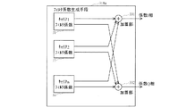
図1には、本発明の一実施例に係る送信機に設けられたピーク電力抑圧手段の構成例を示してある。
本例のピーク電力抑圧手段は、加算器1、2と、遅延調整手段3、4、5と、電力算出手段6と、ピーク電力検出手段7と、ピーク電力抑圧率算出手段8と、乗算器9、10、11、12と、複素乗算手段13、14と、フィルタ係数生成手段15、16と、加算器17、18と、減算器19、20を備えている。
A first embodiment of the present invention will be described.
FIG. 1 shows an example of the configuration of peak power suppression means provided in a transmitter according to an embodiment of the present invention.
The peak power suppression means of this example includes adders 1 and 2, delay adjustment means 3, 4 and 5, power calculation means 6, peak power detection means 7, peak power suppression rate calculation means 8, and
本例のピーク電力抑圧手段において行われる動作の一例を示す。
本例では、複数のキャリアとして2個のキャリア1、2が用いられる場合について示す。
加算器1は、各入力キャリア信号のI相同士を加算合成し、その結果であるマルチキャリア合成信号のI相成分を遅延調整手段3及び電力算出手段6へ出力する。
加算器2は、各入力キャリア信号のQ相同士を加算合成し、その結果であるマルチキャリア合成信号のQ相成分を遅延調整手段3及び電力算出手段6へ出力する。
An example of the operation performed in the peak power suppressing means of this example is shown.
In this example, a case where two carriers 1 and 2 are used as a plurality of carriers is shown.
The adder 1 adds and combines the I phases of the input carrier signals, and outputs the resulting I phase component of the multicarrier combined signal to the delay adjusting unit 3 and the
The adder 2 adds and combines the Q phases of the input carrier signals, and outputs the resulting Q phase component of the multicarrier combined signal to the delay adjusting unit 3 and the
電力算出手段6は、例えば(式1)に示されるように、2個の加算器1、2から入力されたマルチキャリア合成信号のI相成分とQ相成分からサンプル毎の瞬時電力値を計算し、その結果をピーク電力検出手段7へ出力する。
ピーク電力検出手段7は、電力算出手段6から入力されたマルチキャリア合成信号の電力値をサンプル毎に閾値電力と比較し、閾値電力よりも大きい電力値であるサンプルをピーク電力と判断し、その比較結果として、例えば、ピーク電力であればその電力値をピーク電力抑圧率算出手段8へ出力し、ピーク電力でなければ0データをピーク電力抑圧率算出手段8へ出力する。
The power calculation means 6 calculates the instantaneous power value for each sample from the I-phase component and Q-phase component of the multicarrier composite signal input from the two adders 1 and 2 as shown in (Equation 1), for example. Then, the result is output to the peak power detection means 7.
The peak power detection means 7 compares the power value of the multicarrier composite signal input from the power calculation means 6 with the threshold power for each sample, determines that the sample having a power value larger than the threshold power is the peak power, As a comparison result, for example, if the power is peak power, the power value is output to the peak power suppression rate calculation means 8, and if it is not peak power, 0 data is output to the peak power suppression rate calculation means 8.
ここで、閾値電力は、例えば、予め設定されてメモリに記憶されており、その値がピーク電力検出手段7及びピーク電力抑圧率算出手段8に入力される。他の構成例として、通信状況などに応じて、閾値電力が適応的に変更されるような構成が用いられてもよい。
また、閾値電力を低いレベルに設定した場合には、ピーク電力は数サンプル連続して発生することがあるため、連続したピーク電力の内で電力最大のものだけを抑圧対象とすると抑圧過多を防ぐことができる。
なお、本例では、電力値でピーク検出を行っているが、その二乗平方根をとって振幅値でピーク検出を行っても等価である。
Here, the threshold power is preset and stored in the memory, for example, and the value is input to the peak power detection means 7 and the peak power suppression rate calculation means 8. As another configuration example, a configuration may be used in which the threshold power is adaptively changed according to the communication status or the like.
In addition, when the threshold power is set to a low level, peak power may occur continuously for several samples, so excessive suppression is prevented if only the maximum peak power among the continuous peak power is targeted for suppression. be able to.
In this example, the peak detection is performed using the power value, but it is equivalent if the square root is taken and the peak detection is performed using the amplitude value.
ピーク電力抑圧率算出手段8は、ピーク電力検出手段7からの入力に基づいて、ピーク電力と閾値電力との比を求めて、ピーク電力を閾値電力レベルまで抑圧するための比率(ピーク電力抑圧率)を計算し、その結果を4個の乗算器9〜12へ出力する。
本例では、閾値を越えた振幅成分を送信信号から減算することによりピーク電力抑圧を行う構成であり、(式2)に示される計算式でピーク電力抑圧率が算出される。
The peak power suppression rate calculation means 8 obtains a ratio between the peak power and the threshold power based on the input from the peak power detection means 7 and suppresses the peak power to the threshold power level (peak power suppression rate). ) And outputs the result to the four multipliers 9-12.
In this example, the peak power suppression is performed by subtracting the amplitude component exceeding the threshold from the transmission signal, and the peak power suppression rate is calculated by the calculation formula shown in (Expression 2).
遅延調整手段4は、加算器1、2〜ピーク電力抑圧率算出手段8の経路で発生する処理遅延と同等の遅延を第1の入力キャリア信号(キャリア1の信号のIQ成分)に与え、その結果のI相信号を乗算器9へ出力し、その結果のQ相信号を乗算器10へ出力する。
遅延調整手段5は、加算器1、2〜ピーク電力抑圧率算出手段8の経路で発生する処理遅延と同等の遅延を第2の入力キャリア信号(キャリア2の信号のIQ成分)に与え、その結果のI相信号を乗算器11へ出力し、その結果のQ相信号を乗算器12へ出力する。
The delay adjusting means 4 gives a delay equivalent to the processing delay generated in the path of the adders 1 and 2 to the peak power suppression rate calculating means 8 to the first input carrier signal (the IQ component of the signal of the carrier 1). The resulting I-phase signal is output to
The delay adjusting means 5 gives a delay equivalent to the processing delay generated in the path of the adders 1 and 2 to the peak power suppression rate calculating means 8 to the second input carrier signal (the IQ component of the signal of the carrier 2). The resulting I-phase signal is output to
乗算器9は、遅延調整手段4から入力された遅延調整された第1の入力キャリア信号のI相成分とピーク電力抑圧率算出手段8から入力されたピーク電力抑圧率とを乗算し、その結果である第1のピーク電力抑圧信号のI相成分を生成し、それを複素乗算手段13へ出力する。
乗算器10は、遅延調整手段4から入力された遅延調整された第1の入力キャリア信号のQ相成分とピーク電力抑圧率算出手段8から入力されたピーク電力抑圧率とを乗算し、その結果である第1のピーク電力抑圧信号のQ相成分を生成し、それを複素乗算手段13へ出力する。
これらのIQ成分から、第1のピーク電力抑圧信号が構成される。
The
The
From these IQ components, a first peak power suppression signal is constructed.
乗算器11は、遅延調整手段5から入力された遅延調整された第2の入力キャリア信号のI相成分とピーク電力抑圧率算出手段8から入力されたピーク電力抑圧率とを乗算し、その結果である第2のピーク電力抑圧信号のI相成分を生成し、それを複素乗算手段14へ出力する。
乗算器12は、遅延調整手段5から入力された遅延調整された第2の入力キャリア信号のQ相成分とピーク電力抑圧率算出手段8から入力されたピーク電力抑圧率とを乗算し、その結果である第2のピーク電力抑圧信号のQ相成分を生成し、それを複素乗算手段14へ出力する。
これらのIQ成分から、第2のピーク電力抑圧信号が構成される。
The
The
From these IQ components, the second peak power suppression signal is constructed.
フィルタ係数生成手段15は、第1の入力キャリア信号の周波数情報を元にして、第1のピーク電力抑圧信号の周波数帯域を希望の周波数帯に帯域制限する周波数特性を持つ第1のフィルタ係数を生成し、その結果を複素乗算手段13へ出力する。
フィルタ係数生成手段16は、第2の入力キャリア信号の周波数情報を元にして、第2のピーク電力抑圧信号の周波数帯域を希望の周波数帯に帯域制限する周波数特性を持つ第2のフィルタ係数を生成し、その結果を複素乗算手段14へ出力する。
Based on the frequency information of the first input carrier signal, the filter coefficient generation means 15 obtains a first filter coefficient having a frequency characteristic that limits the frequency band of the first peak power suppression signal to a desired frequency band. And the result is output to the complex multiplication means 13.
Based on the frequency information of the second input carrier signal, the filter coefficient generation means 16 obtains a second filter coefficient having a frequency characteristic that limits the frequency band of the second peak power suppression signal to a desired frequency band. The result is output to the complex multiplication means 14.
ここで、各入力キャリア信号の周波数情報は、例えば、予め設定されてメモリに記憶されており、その情報が各フィルタ係数生成手段15、16に入力される。他の構成例として、通信状況などに応じて、各入力キャリア信号の周波数情報が適応的に変更されるような構成が用いられてもよい。
また、各ピーク電力抑圧信号の周波数帯域としては、例えば、各入力キャリア信号と同じであるか、或いは、各入力キャリア信号の周波数帯域に含まれるようにするのが、スペクトル波形の品質上好ましい。
Here, the frequency information of each input carrier signal is preset and stored in a memory, for example, and the information is input to the filter coefficient generation means 15 and 16. As another configuration example, a configuration may be used in which the frequency information of each input carrier signal is adaptively changed according to a communication situation or the like.
In addition, the frequency band of each peak power suppression signal is preferably the same as that of each input carrier signal or included in the frequency band of each input carrier signal in terms of the quality of the spectrum waveform.
複素乗算手段13は、乗算器9、10から入力される第1のピーク電力抑圧信号とフィルタ係数生成手段15から入力される第1のフィルタ係数とを複素乗算し、その結果として、第1の入力キャリア信号に含まれる周波数帯に帯域制限された第1のピーク電力抑圧信号のI相成分を加算器17へ出力し、そのQ相成分を加算器18へ出力する。
複素乗算手段14は、乗算器11、12から入力される第2のピーク電力抑圧信号とフィルタ係数生成手段16から入力される第2のフィルタ係数とを複素乗算し、その結果として、第2の入力キャリア信号に含まれる周波数帯に帯域制限された第2のピーク電力抑圧信号のI相成分を加算器17へ出力し、そのQ相成分を加算器18へ出力する。
ここで、これらの複素乗算としては、例えば、W−CDMA方式の場合には、(式3)に示される計算式が用いられる。
The complex multiplication means 13 performs complex multiplication of the first peak power suppression signal input from the
The complex multiplying
Here, as these complex multiplications, for example, in the case of the W-CDMA system, the calculation formula shown in (Formula 3) is used.
加算器17は、複素乗算手段13から入力される第1のピーク電力抑圧信号のI相成分と複素乗算手段14から入力される第2のピーク電力抑圧信号のI相成分を加算合成し、その結果を減算器19へ出力する。
加算器18は、複素乗算手段13から入力される第1のピーク電力抑圧信号のQ相成分と複素乗算手段14から入力される第2のピーク電力抑圧信号のQ相成分を加算合成し、その結果を減算器20へ出力する。
遅延調整手段3は、電力算出手段6〜加算器17、18の経路で発生する処理遅延と同等の遅延を、加算器1、2から入力されるマルチキャリア合成された入力送信信号に与え、その結果のI相成分を減算器19へ出力し、その結果のQ相成分を減算器20へ出力する。
The
The
The delay adjusting means 3 gives a delay equivalent to the processing delay generated in the path from the power calculating means 6 to the
減算器19は、I相成分について、遅延調整手段3から入力されたマルチキャリア合成された送信信号から、加算器17から入力されたピーク電力抑圧信号を減算し、その結果であるピーク電力が抑圧された送信信号を出力する。
減算器20は、Q相成分について、遅延調整手段3から入力されたマルチキャリア合成された送信信号から、加算器18から入力されたピーク電力抑圧信号を減算し、その結果であるピーク電力が抑圧された送信信号を出力する。
これらI相及びQ相の各々毎に設けられた減算器19、20から出力される信号により、ピーク電力が抑圧された送信信号が構成される。
The
The
A transmission signal in which peak power is suppressed is constituted by signals output from the
ここで、本例では、最大で2キャリア送信の場合を対象としたピーク電力抑圧手段の構成例を示したが、3キャリア以上の場合には、例えば、遅延調整手段、入力キャリア信号とピーク電力抑圧率とを乗算する乗算器、複素乗算手段、フィルタ係数生成手段をキャリア数の分だけ備えればよく、任意のキャリア数に対応することができる。 Here, in this example, the configuration example of the peak power suppression unit intended for the case of maximum two-carrier transmission is shown. However, in the case of three or more carriers, for example, the delay adjustment unit, the input carrier signal, and the peak power It suffices to provide a multiplier for multiplying the suppression rate, a complex multiplication unit, and a filter coefficient generation unit for the number of carriers, and can handle any number of carriers.
以上のように、本例のピーク電力抑圧手段では、N個(Nは1以上の整数)のキャリアを合成したマルチキャリア送信信号に存在するピーク電力を抑圧するに際して、各キャリア周波数にデジタル直交変調が施されたN個のキャリア信号を入力信号とし、前記N個の入力キャリア信号に対してマルチキャリア加算を行うマルチキャリア加算手段1、2と、前記マルチキャリア加算手段1、2からの出力信号に対してサンプル毎に瞬時電力値を算出する電力算出手段6と、前記電力算出手段6により算出された瞬時電力値と設定閾値とを比較して、設定閾値よりも大きい瞬時電力値をピーク電力として検出するピーク電力検出手段7と、前記ピーク電力検出手段7により検出されたピーク電力に対してピーク電力の抑圧率を算出するピーク電力抑圧率算出手段8と、前記ピーク電力抑圧率算出手段8により算出されたピーク電力抑圧率と前記N個の入力キャリア信号とをそれぞれ乗算し、キャリア毎にピーク電力抑圧信号を出力するN個の乗算手段9〜12(本例では、それぞれ、I相及びQ相に対応して2個の乗算器から構成されている)と、前記N個のピーク電力抑圧信号に対してその周波数帯域をそれぞれ希望の周波数帯に帯域制限する周波数特性を持ったフィルタ係数を複素乗算し、帯域制限が施されたピーク電力抑圧信号を出力するN個の複素乗算手段13、14と、前記N個の複素乗算手段13、14からの出力信号に対して加算合成を行って1つのピーク電力抑圧信号を出力する加算手段17、18(本例では、I相及びQ相に対応して2個の加算器から構成されている)と、前記加算手段17、18より出力されたピーク電力抑圧信号を前記マルチキャリア加算手段1、2より出力されたマルチキャリア送信信号から減算してピーク電力が抑圧された送信信号を出力する減算手段19、20(本例では、I相及びQ相に対応して2個の減算器から構成されている)を備えた。
As described above, in the peak power suppression means of this example, when suppressing the peak power present in a multicarrier transmission signal obtained by combining N (N is an integer of 1 or more) carriers, digital orthogonal modulation is performed on each carrier frequency. The N carrier signals subjected to the above are used as input signals, multicarrier addition means 1 and 2 for performing multicarrier addition on the N input carrier signals, and output signals from the multicarrier addition means 1 and 2 The power calculation means 6 for calculating the instantaneous power value for each sample, the instantaneous power value calculated by the power calculation means 6 and the set threshold value are compared, and the instantaneous power value larger than the set threshold value is calculated as the peak power. The peak power detecting means 7 for detecting the peak power and the peak power for calculating the peak power suppression rate for the peak power detected by the peak power detecting means 7 A peak
なお、本例の送信機に設けられた図1に示されるピーク電力抑圧手段では、フィルタ係数生成手段15、16により生成される各キャリア信号のフィルタ係数と各キャリア信号とを複素乗算手段13、14により複素乗算する機能により係数乗算手段が構成されており、当該乗算結果を加算器17、18により全てのキャリア信号について加算する機能により総和手段が構成されており、電力算出手段6やピーク電力検出手段7やピーク電力抑圧率算出手段8によりピーク電力抑圧率(ピークレベル抑圧率の一例)を生成する機能により抑圧率生成手段が構成されており、乗算器9〜12により各キャリア信号に対してピーク電力抑圧率を乗算する機能により抑圧率乗算手段が構成されており、ピーク電力抑圧信号(ピークレベル抑圧信号の一例)を生成するこれらの機能により抑圧信号生成手段が構成されており、また、減算器19、20によりマルチキャリア信号からピーク電力抑圧信号を減算する機能により抑圧信号減算手段が構成されている。
In the peak power suppression means shown in FIG. 1 provided in the transmitter of this example, the complex multiplication means 13, the filter coefficient of each carrier signal generated by the filter coefficient generation means 15, 16 and each carrier signal, 14 is configured by a function of complex multiplication by 14, and a summation unit is configured by a function of adding the multiplication results for all the carrier signals by the
本発明の第2実施例を説明する。
図2には、本発明の一実施例に係る送信機に設けられたピーク電力抑圧手段の構成例を示してある。
本例のピーク電力抑圧手段は、遅延調整手段31、32、33と、電力算出手段34と、ピーク電力検出手段35と、ピーク電力抑圧率算出手段36と、乗算器37、38、39、40と、複素乗算手段41、42と、フィルタ係数生成手段43、44と、加算器45、46と、減算器47、48を備えている。
A second embodiment of the present invention will be described.
FIG. 2 shows a configuration example of peak power suppression means provided in the transmitter according to one embodiment of the present invention.
The peak power suppression means of this example includes delay adjustment means 31, 32, 33, power calculation means 34, peak power detection means 35, peak power suppression rate calculation means 36, and
ここで、図2に示されるピーク電力抑圧手段の構成や動作は、キャリア信号(キャリア1、2)とそのキャリア信号をマルチキャリア合成した信号(合成信号)を入力信号とする点を除いて、図1に示されるピーク電力抑圧手段の構成や動作と同様であり、図2に示される各処理部31〜48についても図1に示される各処理部3〜20と同様な動作を行う。
Here, the configuration and operation of the peak power suppression means shown in FIG. 2 is that the carrier signal (carriers 1 and 2) and a signal obtained by multicarrier synthesis of the carrier signal (synthesized signal) are input signals, The configuration and operation of the peak power suppression means shown in FIG. 1 are the same, and the
なお、本例のピーク電力抑圧手段についても、例えば図1の場合と同様に、最大で2キャリア送信の場合を対象としたものであるが、3キャリア以上の場合には、遅延調整手段、入力キャリア信号とピーク電力抑圧率とを乗算する乗算器、複素乗算手段、フィルタ係数生成手段をキャリア数の分だけ備えればよく、任意のキャリア数に対応することができる。 Note that the peak power suppression means of this example is also targeted for the case of maximum two-carrier transmission, for example, as in the case of FIG. 1, but in the case of three or more carriers, the delay adjustment means, the input It is only necessary to provide a multiplier, a complex multiplier, and a filter coefficient generator for multiplying the carrier signal and the peak power suppression rate by the number of carriers, so that any number of carriers can be handled.
以上のように、本例のピーク電力抑圧手段では、各キャリア周波数にデジタル直交変調が施されたN(Nは1以上の整数)個のキャリア信号と、そのN個のキャリア信号をマルチキャリア合成した信号を入力信号とし、電力算出手段34は前記入力マルチキャリア合成信号に対してサンプル毎に瞬時電力値を算出し、減算器47、48は加算手段45、46より出力されたピーク電力抑圧信号を前記入力マルチキャリア信号から減算して、ピーク電力が抑圧された送信信号を出力する。 As described above, in the peak power suppression means of this example, N (N is an integer of 1 or more) carrier signals whose digital orthogonal modulation is performed on each carrier frequency and the N carrier signals are multi-carrier combined. The power calculation means 34 calculates an instantaneous power value for each sample with respect to the input multicarrier composite signal, and the subtractors 47 and 48 output peak power suppression signals output from the addition means 45 and 46, respectively. Is subtracted from the input multicarrier signal to output a transmission signal in which peak power is suppressed.
本発明の第3実施例を説明する。
図3には、本発明の一実施例に係る送信機に設けられたピーク電力抑圧手段の構成例を示してある。
本例のピーク電力抑圧手段は、遅延調整手段51、52と、電力算出手段53と、ピーク電力検出手段54と、ピーク電力抑圧率算出手段55と、乗算器56、57と、複素乗算手段58と、フィルタ係数生成手段59と、加算器60、61と、キャリアパワー検出手段62を備えている。
A third embodiment of the present invention will be described.
FIG. 3 shows a configuration example of peak power suppression means provided in the transmitter according to one embodiment of the present invention.
The peak power suppression means of this example includes delay adjustment means 51 and 52, power calculation means 53, peak power detection means 54, peak power suppression rate calculation means 55,
ここで、遅延調整手段51、52、電力算出手段53、ピーク電力検出手段54、ピーク電力抑圧率算出手段55、乗算器56、57、複素乗算手段58、減算器60、61については、例えば、図16に示されるピーク電力抑圧手段の各処理部311〜317、319と同様な動作を行い、本例では、詳しい説明は省略する。
Here, for the delay adjustment means 51 and 52, the power calculation means 53, the peak power detection means 54, the peak power suppression rate calculation means 55, the
キャリアパワー検出手段62は、マルチキャリア合成前の各キャリア信号の平均電力値を求め、その結果をフィルタ係数生成手段59へ出力する。マルチキャリア合成前であれば、キャリア周波数にデジタル直交変調される前でも後でもその平均電力値は変わらない。平均電力を求める時間区間は、例えば、バースト信号に対応するためにはあまり長い時間幅では都合が悪く、フィルタ係数のタップ長程度(2〜5chip)の時間幅とするのが妥当である。 The carrier power detection means 62 obtains the average power value of each carrier signal before multicarrier combination and outputs the result to the filter coefficient generation means 59. Before the multicarrier combination, the average power value does not change before or after digital quadrature modulation to the carrier frequency. For example, the time interval for obtaining the average power is not convenient for a long time width in order to cope with a burst signal, and it is appropriate to set the time width to be about the tap length (2 to 5 chips) of the filter coefficient.
フィルタ係数生成手段59は、送信キャリア周波数の情報(周波数情報)と共にキャリアパワー検出手段62によって求められた各キャリア信号の平均電力値を入力し、各キャリアに対応したフィルタ係数に平均電力の大小に応じた重み係数を乗算して、合成したフィルタ係数を生成し、その結果を複素乗算手段58へ出力する。 The filter coefficient generation means 59 inputs the average power value of each carrier signal obtained by the carrier power detection means 62 together with the transmission carrier frequency information (frequency information), and sets the average power to the filter coefficient corresponding to each carrier. The combined weighting coefficient is multiplied to generate a combined filter coefficient, and the result is output to the complex multiplication means 58.
具体例を示す。
フィルタ係数生成手段59は、入力された各キャリアの平均電力の差に基づいて、平均電力が小さいキャリアに対しては1よりも小さい重み係数をその平均電力が小さい側のキャリアに対応するフィルタ係数に乗算する。例えば、2つのキャリアのレベル差が5dBであれば、レベルが小さいキャリアのフィルタ係数には−5dB相当の値をとる重み係数を乗算することでフィルタのゲインが5dB落ちる。
図4には、このときのフィルタの周波数特性の一例を示してある。横軸は周波数[MHz]を表しており、縦軸はゲイン[dB]を表している。
A specific example is shown.
Based on the difference in the average power of the inputted carriers, the filter coefficient generation means 59 applies a weight coefficient smaller than 1 to a carrier having a smaller average power, and a filter coefficient corresponding to the carrier having a smaller average power. Multiply by. For example, if the level difference between two carriers is 5 dB, the filter gain of the filter is lowered by 5 dB by multiplying the filter coefficient of a carrier with a low level by a weighting coefficient that takes a value corresponding to −5 dB.
FIG. 4 shows an example of the frequency characteristic of the filter at this time. The horizontal axis represents frequency [MHz], and the vertical axis represents gain [dB].
以上のように、本例のピーク電力抑圧手段では、N個(Nは1以上の整数)のキャリアを合成したマルチキャリア送信信号に存在するピーク電力を抑圧するに際して、入力マルチキャリア合成信号に対してサンプル毎に瞬時電力値を算出する電力算出手段53と、前記電力算出手段53により算出された瞬時電力値と設定閾値とを比較して、設定閾値よりも大きい瞬時電力値をピーク電力として検出するピーク電力検出手段54と、前記ピーク電力検出手段54により検出されたピーク電力に対してピーク電力の抑圧率を算出するピーク電力抑圧率算出手段55と、前記ピーク電力抑圧率算出手段55により算出されたピーク電力抑圧率と前記入力マルチキャリア合成信号とを乗算してピーク電力抑圧信号を出力する乗算手段56、57と、前記ピーク電力抑圧信号に対してその周波数帯域を希望の周波数帯に帯域制限する周波数特性を持ち且つ各キャリアのパワーに応じてキャリアの通過帯域毎にゲイン調整されたフィルタ係数を複素乗算して、帯域制限が施されたピーク電力抑圧信号を出力する複素乗算手段58と、前記複素乗算手段58からの出力信号を前記入力マルチキャリア合成信号から減算して、ピーク電力が抑圧された送信信号を出力する減算器60、61を備えた。
As described above, in the peak power suppressing means of this example, when suppressing the peak power existing in the multicarrier transmission signal obtained by combining N (N is an integer of 1 or more) carriers, The power calculation means 53 for calculating the instantaneous power value for each sample and the instantaneous power value calculated by the power calculation means 53 and the set threshold are compared, and an instantaneous power value larger than the set threshold is detected as peak power. Calculated by the peak power detection means 54, the peak power suppression rate calculation means 55 for calculating the peak power suppression rate for the peak power detected by the peak power detection means 54, and the peak power suppression rate calculation means 55. Multiplying means 56 and 57 for multiplying the peak power suppression rate and the input multicarrier composite signal to output a peak power suppression signal; The peak power suppression signal has a frequency characteristic that limits the frequency band to a desired frequency band, and complex-multiplies a filter coefficient gain-adjusted for each carrier pass band according to the power of each carrier, A
なお、本例の送信機に設けられた図3に示されるピーク電力抑圧手段では、キャリアパワー検出手段62やフィルタ係数生成手段59により各キャリア信号のレベルに応じたフィルタ係数を生成する機能により係数生成手段が構成されており、フィルタ係数生成手段59によりフィルタ係数を全てのキャリア信号について総和する機能により係数総和手段が構成されており、当該総和結果とマルチキャリア信号とを複素乗算手段58により乗算する機能により信号乗算手段が構成されており、電力算出手段53やピーク電力検出手段54やピーク電力抑圧率算出手段55によりピーク電力抑圧率(ピークレベル抑圧率の一例)を生成する機能により抑圧率生成手段が構成されており、乗算器56、57によりマルチキャリア信号に対してピーク電力抑圧率を乗算する機能により抑圧率乗算手段が構成されており、ピーク電力抑圧信号(ピークレベル抑圧信号の一例)を生成するこれらの機能により抑圧信号生成手段が構成されており、また、減算器60、61によりマルチキャリア信号からピーク電力抑圧信号を減算する機能により抑圧信号減算手段が構成されている。
In the peak power suppression means shown in FIG. 3 provided in the transmitter of this example, the coefficient is generated by the function of generating the filter coefficient corresponding to the level of each carrier signal by the carrier power detection means 62 and the filter coefficient generation means 59. The generation means is configured, and the coefficient summation means is configured by the function of summing the filter coefficients for all the carrier signals by the filter coefficient generation means 59. The complex multiplication means 58 multiplies the summation result and the multicarrier signal. The signal multiplying unit is configured by the function of performing the suppression, and the suppression rate by the function of generating the peak power suppression rate (an example of the peak level suppression rate) by the
本発明の第4実施例を説明する。
図9には、本発明の一実施例に係る送信機に設けられたピーク電力抑圧手段101の構成例を示してある。
本例のピーク電力抑圧手段101は、4個の遅延調整手段111、112、113、114と、キャリア信号検出手段115と、レベル差検出手段116と、フィルタ係数生成手段117と、電力算出手段118と、ピーク電力検出手段119と、ピーク電力抑圧率算出手段120と、乗算手段121と、複素乗算手段122と、減算手段123を備えている。
A fourth embodiment of the present invention will be described.
FIG. 9 shows a configuration example of the peak power suppression means 101 provided in the transmitter according to one embodiment of the present invention.
The peak
本例のピーク電力抑圧手段101において行われる動作の一例を示す。
本例では、複数のキャリア(キャリア0〜キャリアm)の合成信号のI相成分及びQ相成分がピーク電力抑圧手段101に入力される。
各遅延調整手段111〜114は、各処理系統の出力端で演算されるタイミングが揃うように、入力信号に対して遅延調整を行う。遅延調整手段111は遅延させた入力信号を減算手段123へ出力し、遅延調整手段112は遅延させた入力信号を乗算手段121へ出力し、遅延調整手段113は遅延させた入力信号を電力算出手段118へ出力し、遅延調整手段114は遅延させた入力信号をキャリア信号検出手段115へ出力する。
An example of the operation performed in the peak power suppression means 101 of this example will be shown.
In this example, the I-phase component and the Q-phase component of the combined signal of a plurality of carriers (
Each delay adjusting unit 111 to 114 performs delay adjustment on the input signal so that the timings calculated at the output ends of the respective processing systems are aligned. The delay adjustment means 111 outputs the delayed input signal to the subtraction means 123, the delay adjustment means 112 outputs the delayed input signal to the multiplication means 121, and the delay adjustment means 113 outputs the delayed input signal to the power calculation means. The
電力算出手段118は、遅延調整手段113から入力された信号のI相成分とQ相成分により、サンプル毎の瞬時電力を計算し、その結果をピーク電力検出手段119へ出力する。
ピーク電力検出手段119は、電力算出手段118から入力された入力信号の電力値をサンプル毎に所定の閾値電力と比較して、閾値電力よりも大きい電力値であるサンプルをピーク電力と判断し、その比較結果をピーク電力抑圧率算出手段120へ出力する。この比較結果として、例えば、ピーク電力であればその電力値を出力し、ピーク電力でなければ0データを出力する。
ピーク電力抑圧率算出手段120は、ピーク電力検出手段119から入力されるピーク電力と所定の閾値電力との比を求めて、ピーク電力を閾値電力レベルまで抑圧するための比率(ピーク電力抑圧率)を計算し、その結果を乗算手段121へ出力する。
The power calculation means 118 calculates the instantaneous power for each sample from the I-phase component and Q-phase component of the signal input from the delay adjustment means 113, and outputs the result to the peak power detection means 119.
The peak
The peak power suppression rate calculation means 120 obtains the ratio between the peak power input from the peak power detection means 119 and a predetermined threshold power, and suppresses the peak power to the threshold power level (peak power suppression rate). And the result is output to the multiplication means 121.
乗算手段121は、例えばI相成分に対応した乗算器及びQ相成分に対応した乗算器を有しており、遅延調整手段112から入力される遅延調整されたピーク検出時の入力信号のIQ成分とピーク電力抑圧率算出手段120から入力されるピーク電力抑圧率を乗算して、ピーク電力の抑圧振幅成分であるピーク電力抑圧信号を生成し、それを複素乗算手段122へ出力する。 The multiplication means 121 has, for example, a multiplier corresponding to the I-phase component and a multiplier corresponding to the Q-phase component, and the IQ component of the input signal at the time of the delay adjustment peak detection input from the delay adjustment means 112. Is multiplied by the peak power suppression rate input from the peak power suppression rate calculation means 120 to generate a peak power suppression signal which is a suppression amplitude component of the peak power, and is output to the complex multiplication means 122.
キャリア信号検出手段115は、遅延調整手段114から入力された信号のI相成分とQ相成分により、各キャリアの帯域信号を抽出し、その結果をレベル差検出手段116へ出力する。
図10には、キャリア信号検出手段115の一構成例として、キャリア信号検出手段115aの構成例を示してある。
本例のキャリア信号検出手段115aは、フーリエ変換部131を備えている。
フーリエ変換部131は、例えばFFT(Fast Fourier Transform)によりフーリエ変換を行う機能を有しており、遅延調整手段114からの入力信号(マルチキャリア合成信号のIQ成分)に対して各キャリア信号の周波数成分の信号(IQ成分)を抽出し、その結果をレベル差検出手段116へ出力する。
The carrier
FIG. 10 shows a configuration example of the carrier
The carrier signal detection means 115a of this example includes a
The
図11には、キャリア信号検出手段115の他の一構成例として、キャリア信号検出手段115bの構成例を示してある。
本例のキャリア信号検出手段115bは、フーリエ変換部141と、複数の平均化部A0〜Amを備えている。
フーリエ変換部141は、例えばFFTによりフーリエ変換を行う機能を有しており、遅延調整手段114からの入力信号(マルチキャリア合成信号のIQ成分)に対して各キャリア信号の周波数成分の信号(IQ成分)を抽出して各平均化部A0〜Amへ出力する。
FIG. 11 shows a configuration example of the carrier
The carrier signal detection means 115b of this example includes a
The
各平均化部A0〜Amは、それぞれ各キャリア0〜mに対応しており、フーリエ変換部141から入力される各キャリア信号に対して平均化を行い、その結果(IQ成分)をレベル差検出手段116へ出力する。
ここで、平均化による効果としては、例えば、本例では、フィルタ係数がキャリアレベルの大小関係によりレベルが補正され、フーリエ変換後の各キャリアの信号データを、所定の区間(例えば、フィルタ係数長分の区間)で、平均化することにより、ピーク時周辺のキャリアレベルを考慮した補正を施すことが可能となる。
Each averaging unit A0 to Am corresponds to each
Here, as an effect of averaging, for example, in this example, the filter coefficient is corrected for the level of the carrier level, and the signal data of each carrier after Fourier transform is converted into a predetermined section (for example, filter coefficient length). By averaging in the minute interval), it is possible to perform correction in consideration of the carrier level around the peak time.
図12には、キャリア信号検出手段115の他の一構成例として、キャリア信号検出手段115cの構成例を示してある。
本例のキャリア信号検出手段115cは、フーリエ変換部151と、複数のフィルタ部B0〜Bmを備えている。
フーリエ変換部151は、例えばFFTによりフーリエ変換を行う機能を有しており、遅延調整手段114からの入力信号(マルチキャリア合成信号のIQ成分)に対して各キャリア信号の周波数成分の信号(IQ成分)を抽出して各フィルタ部B0〜Bmへ出力する。
FIG. 12 shows a configuration example of the carrier
The carrier signal detection means 115c of this example includes a
The
各フィルタ部B0〜Bmは、それぞれ各キャリア0〜mに対応しており、フーリエ変換部151から入力される各キャリア信号に対して帯域制限を行い、その結果(IQ成分)をレベル差検出手段116へ出力する。
ここで、帯域制限による効果としては、フーリエ変換後の各キャリア信号に帯域制限を施すことにより、キャリア信号の検出精度を向上させることが可能となる。
レベル差検出手段116は、キャリア信号検出手段115から入力される各キャリアの帯域信号により、各キャリア間のレベル差(例えば、レベル比やレベル補正値)を算出し、その結果をフィルタ係数生成手段117へ出力する。
Each filter unit B0 to Bm corresponds to each
Here, as an effect of band limitation, carrier signal detection accuracy can be improved by band-limiting each carrier signal after Fourier transform.
The level
図13には、レベル差検出手段116の一構成例として、レベル差検出手段116aの構成例を示してある。
本例のレベル差検出手段116aは、複数のキャリア電力算出手段C0〜Cmと、複数のレベル比算出手段D0〜Dmと、総和電力算出手段161を備えている。
各キャリア電力算出手段C0〜Cmは、それぞれ各キャリア0〜mに対応しており、キャリア信号検出手段115から出力される各キャリアの帯域信号(IQ成分)を入力して、各キャリア信号の電力を算出し、その結果を各レベル比算出手段D0〜Dmへ出力するとともに総和電力算出手段161へ出力する。
FIG. 13 shows a configuration example of the level
The level difference detection means 116a of this example includes a plurality of carrier power calculation means C0 to Cm, a plurality of level ratio calculation means D0 to Dm, and a total power calculation means 161.
Each of the carrier power calculation means C0 to Cm corresponds to each of the
総和電力算出手段161は、複数のキャリア電力算出手段C0〜Cmから入力された電力値の総和を算出し、その結果(総和電力)を各レベル比算出手段D0〜Dmへ出力する。
各レベル比算出手段D0〜Dmは、それぞれ各キャリア0〜mに対応しており、各キャリア電力算出手段C0〜Cmから入力された電力値と総和電力算出手段161から入力された総和電力値に基づいて、各キャリア毎にレベル比を算出し、その結果をフィルタ係数生成手段117へ出力する。このレベル比としては、例えば、(各キャリア毎の電力値/総和電力値)を用いることができる。
The total power calculation means 161 calculates the total sum of the power values input from the plurality of carrier power calculation means C0 to Cm, and outputs the result (total power) to each level ratio calculation means D0 to Dm.
Each level ratio calculation means D0 to Dm corresponds to each
図14には、レベル差検出手段116の他の一構成例として、レベル差検出手段116bの構成例を示してある。
本例のレベル差検出手段116bは、複数のキャリア電力算出手段E0〜Emと、比較部171を備えている。
各キャリア電力算出手段E0〜Emは、それぞれ各キャリア0〜mに対応しており、キャリア信号検出手段115から出力される各キャリアの帯域信号(IQ成分)を入力して、各キャリア信号の電力を算出し、その結果を比較部171へ出力する。
FIG. 14 shows a configuration example of the level
The level difference detection means 116b of this example includes a plurality of carrier power calculation means E0 to Em and a
Each of the carrier power calculation means E0 to Em corresponds to each of the
比較部171は、複数のキャリア電力算出手段E0〜Emから入力された各キャリア毎の電力値に基づいて、その大小の比較を行って、ランク分けを行い、各キャリアについてランクに応じた重み係数をフィルタ係数生成手段117へ出力する。
なお、本例の構成では、図13に示される構成と比べて、精度は劣るが、ハードウエア的に回路規模を低減することが可能である。
The
The configuration of this example is inferior in accuracy to the configuration shown in FIG. 13, but the circuit scale can be reduced by hardware.
フィルタ係数生成手段117は、送信信号のキャリア周波数情報と、レベル差検出手段116からの入力に基づいて、ピーク電力抑圧信号の周波数帯域を希望の周波数帯に帯域制限する周波数特性を持つフィルタ係数を生成し、その結果を複素乗算手段122へ出力する。
ここで、ピーク電力抑圧信号の周波数帯域としては、例えば、送信信号と同じであるか、或いは、送信信号の周波数帯域に含まれるようにするのが、スペクトル波形の品質上好ましい。
なお、ここで生成されるフィルタ係数は、任意のキャリア周波数に対応するため、通常は複素係数の形式である。
さらに、本例のフィルタ係数生成手段117では、レベル差検出手段116により算出された各キャリア間のレベル比の情報(又は、重み係数の情報)に基づいて、フィルタ係数に重みを与える。例えば、レベルの大きいキャリアの方が、フィルタ係数が大きくなるようにし、生成されるピーク電力抑圧信号が大きくなるようにする。
Based on the carrier frequency information of the transmission signal and the input from the level difference detection means 116, the filter coefficient generation means 117 obtains a filter coefficient having a frequency characteristic that limits the frequency band of the peak power suppression signal to a desired frequency band. And outputs the result to the complex multiplication means 122.
Here, the frequency band of the peak power suppression signal is preferably the same as, for example, the transmission signal or included in the frequency band of the transmission signal in terms of spectral waveform quality.
In addition, since the filter coefficient produced | generated here respond | corresponds to arbitrary carrier frequencies, it is the form of a complex coefficient normally.
Furthermore, the filter coefficient generation means 117 of this example gives weights to the filter coefficients based on the level ratio information (or weight coefficient information) between the carriers calculated by the level difference detection means 116. For example, the filter coefficient is increased for a carrier having a higher level so that the generated peak power suppression signal is increased.
図15には、フィルタ係数生成手段117の一構成例として、フィルタ係数生成手段117aの構成例を示してある。
本例のフィルタ係数生成手段117aは、複数のフィルタ係数格納部F0〜Fmと、複数の乗算部G0〜Gmと、2個の加算部181、182を備えている。
各フィルタ係数格納部F0〜Fmは、それぞれ各キャリア0〜mに対応しており、例えばメモリから構成されており、各送信キャリアに対応した周波数特性を持つフィルタ係数(IQ成分)を格納しており、それを各乗算部G0〜Gmへ出力する。
FIG. 15 shows a configuration example of the filter
The filter coefficient generation means 117a of this example includes a plurality of filter coefficient storage units F0 to Fm, a plurality of multiplication units G0 to Gm, and two
Each filter coefficient storage unit F0 to Fm corresponds to each
各乗算部G0〜Gmは、各フィルタ係数格納部F0〜Fmから入力された各キャリア毎のフィルタ係数と、レベル差検出手段116から入力された各キャリアのレベル比に基づく補正値(例えば、重み係数)とを乗算し、その結果のI相成分を加算部181へ出力し、その結果のQ相成分を加算部182へ出力する。
加算部181は、複数の乗算部G0〜Gmから入力されるI相成分を加算し、その結果をフィルタ係数のI相成分として複素乗算手段122へ出力する。
加算部182は、複数の乗算部G0〜Gmから入力されるQ相成分を加算し、その結果をフィルタ係数のQ相成分として複素乗算手段122へ出力する。
Each of the multipliers G0 to Gm is a correction value (for example, a weight) based on the filter coefficient for each carrier input from each filter coefficient storage unit F0 to Fm and the level ratio of each carrier input from the level difference detection means 116. The resultant I-phase component is output to the adding
The
The adder 182 adds the Q-phase components input from the multiple multipliers G0 to Gm, and outputs the result to the
複素乗算手段122は、乗算手段121から入力されたピーク電力抑庄信号(IQ成分)とフィルタ係数生成手段117から入力されたフィルタ係数(IQ成分)とを複素乗算し、希望の周波数帯に帯域制限されたピーク電力抑圧信号(IQ成分)を減算手段123へ出力する。
減算手段123は、例えばI相成分に対応した減算器及びQ相成分に対応した減算器を有しており、遅延調整手段111から入力された信号(IQ成分)から、複素乗算手段122から入力された帯域制限されたピーク電力抑圧信号(IQ成分)を減算し、その結果であるピーク電力を低減した信号(IQ成分)を出力する。
The
The subtracting
以上のように、本例のピーク電力抑圧手段101では、複数のキャリアの信号を合成したマルチキャリア信号(送信信号)に存在するピーク電力を抑圧するに際して、マルチキャリア加算が行われた信号(マルチキャリア信号)に対して瞬時電力値を算出する電力算出手段118と、電力算出手段118により算出された瞬時電力値と設定閾値とを比較して、設定閾値よりも大きい瞬時電力値をピーク電力として検出するピーク電力検出手段119と、ピーク電力検出手段119により検出されたピーク電力に対してピーク電力の抑圧率を算出するピーク電力抑圧率算出手段120と、前記マルチキャリア信号から各キャリア周波数を有する信号を抽出するキャリア信号検出手段115と、キャリア信号検出手段115からの出力よりキャリア間のレベル差を算出するレベル差検出手段116と、レベル差検出手段116からの出力とキャリア周波数に対応して帯域制限を施されたフィルタ係数より当該フィルタ係数の補正を行うフィルタ係数生成手段117と、前記マルチキャリア信号とピーク電力抑圧率算出手段120からの出力であるピーク電力抑圧率とを乗算する乗算手段121と、乗算手段121からの出力(ピーク電力抑圧信号)とフィルタ係数生成手段117からの出力(フィルタ係数)とを複素乗算する複素乗算手段122と、複素乗算手段122から出力されたピーク電力抑圧信号を前記マルチキャリア信号(送信信号)から減算して、ピーク電力が抑圧された送信信号を出力する減算手段123を備えた。
As described above, in the peak
従って、本例のピーク電力抑圧手段101を使用した場合には、各キャリア信号を抽出し、電力値によるフィルタ係数の重み付けを行うことにより、例えば、従来技術のピーク電力抑圧手段で発生したキャリア間レベルのアンバランス時におけるスペクトル劣化という不具合の現象を発生させないことを実現することができる。なお、例えば、キャリア検出機能を追加した分だけハードウエア規模が増加することが考えられるが、ピーク電力抑圧手段というモジュールの枠で考慮した場合には、容易に他のシステムヘの移行が可能である。
Therefore, when the peak
一構成例として、図10に示されるように、キャリア信号検出手段115aは、前記マルチキャリア信号からキャリア毎の周波数成分を抽出することをフーリエ変換によって実現するフーリエ変換部131を有する。
他の一構成例として、図11に示されるように、キャリア信号検出手段115bは、前記マルチキャリア信号からキャリア毎の周波数成分を抽出することをフーリエ変換によって実現するフーリエ変換部141と、フーリエ変換部141からの出力信号を平均化する平均化部A0〜Amから構成される。
他の一構成例として、図12に示されるように、キャリア信号検出手段115cは、前記マルチキャリア信号からキャリア毎の周波数成分を抽出することをフーリエ変換によって実現するフーリエ変換部151と、フーリエ変換部151からの出力信号を帯域制限するフィルタ部B0〜Bmから構成される。
As an example of the configuration, as shown in FIG. 10, the carrier
As another configuration example, as illustrated in FIG. 11, the carrier
As another configuration example, as shown in FIG. 12, the carrier
一構成例として、図13に示されるように、レベル差検出手段116aは、キャリア信号検出手段115からの出力信号より複数のキャリアについてキャリア毎の電力値を算出するキャリア電力算出手段C0〜Cmと、キャリア電力算出手段C0〜Cmから出力される電力の総和電力を算出する総和電力算出手段161と、総和電力算出手段161から出力される総和電力とキャリア電力算出手段C0〜Cmから出力される電力よりキャリア間のレベル比を算出するレベル比算出手段D0〜Dmから構成される。
他の一構成例として、図14に示されるように、レベル差検出手段116bは、キャリア信号検出手段115からの出力信号より複数のキャリアについてキャリア毎の電力値を算出するキャリア電力算出手段E0〜Emと、キャリア電力算出手段E0〜Emからの出力において各キャリアのレベルの大小関係を検出する比較部171から構成される。また、例えば、比較部171からの出力により決定される重み係数とキャリア電力算出手段E0〜Emからの出力とを乗算する重み乗算手段の機能を備えてもよい。
As an example of the configuration, as shown in FIG. 13, the level
As another configuration example, as shown in FIG. 14, the level
なお、本例の送信機に設けられた図9(及び図10〜15)に示されるピーク電力抑圧手段では、キャリア信号検出手段115やレベル差検出手段116やフィルタ係数生成手段117のフィルタ係数格納部F0〜Fmや乗算部G0〜Gmにより各キャリア信号のレベルに応じたフィルタ係数を生成する機能により係数生成手段が構成されており、フィルタ係数生成手段117の加算部181、182によりフィルタ係数を全てのキャリア信号について総和する機能により係数総和手段が構成されており、当該総和結果とマルチキャリア信号とを複素乗算手段122により乗算する機能により信号乗算手段が構成されており、電力算出手段118やピーク電力検出手段119やピーク電力抑圧率算出手段120によりピーク電力抑圧率(ピークレベル抑圧率の一例)を生成する機能により抑圧率生成手段が構成されており、乗算手段121によりマルチキャリア信号に対してピーク電力抑圧率を乗算する機能により抑圧率乗算手段が構成されており、ピーク電力抑圧信号(ピークレベル抑圧信号の一例)を生成するこれらの機能により抑圧信号生成手段が構成されており、また、減算手段123によりマルチキャリア信号からピーク電力抑圧信号を減算する機能により抑圧信号減算手段が構成されている。
Note that the peak power suppression means shown in FIG. 9 (and FIGS. 10 to 15) provided in the transmitter of this example stores the filter coefficients of the carrier signal detection means 115, the level difference detection means 116, and the filter coefficient generation means 117. Coefficient generating means is configured by the function of generating filter coefficients corresponding to the level of each carrier signal by the parts F0 to Fm and the multipliers G0 to Gm, and the filter coefficients are added by the
本発明の第5実施例を説明する。
図5には、本発明の一実施例に係る送信増幅器の構成例を示してある。
本例の送信増幅器は、デジタル変調手段71と、ピーク電力抑圧手段72と、D/A(Digital to Analog)コンバータ73と、アナログ直交変調手段74と、電力増幅器75を備えている。
ここで、ピーク電力抑圧手段72としては、種々なものが用いられてもよく、例えば、図1、図2、図3、図9に示されるようなものを用いることができる。
A fifth embodiment of the present invention will be described.
FIG. 5 shows a configuration example of a transmission amplifier according to an embodiment of the present invention.
The transmission amplifier of this example includes digital modulation means 71, peak power suppression means 72, D / A (Digital to Analog)
Here, various types of peak power suppression means 72 may be used, and for example, those shown in FIGS. 1, 2, 3, and 9 can be used.
本例の送信増幅器において行われる動作の一例を示す。
デジタル変調手段71は、入力されたベースバンド信号に対して、キャリア毎に、帯域制限、希望のサンプリング周波数へのアップサンプリング、希望のキャリア周波数へのデジタル直交変調を行い、その結果をピーク電力抑圧手段72へ出力する。
ピーク電力抑圧手段72は、デジタル変調手段71から入力された信号に存在するピーク電力を閾値レベルまで抑圧し、その結果をD/Aコンバータ73へ出力する。
An example of the operation performed in the transmission amplifier of this example is shown.
The digital modulation means 71 performs band limitation, up-sampling to a desired sampling frequency, digital quadrature modulation to a desired carrier frequency for each carrier on the input baseband signal, and the peak power suppression is performed on the result. It outputs to the
The peak
D/Aコンバータ73は、ピーク電力抑圧手段72から入力されたデジタル送信信号をアナログ信号へ変換して、アナログ直交変調手段74へ出力する。
アナログ直交変調手段74は、D/Aコンバータ73から入力された信号を希望の無線周波数(RF:Radio Frequency)帯の信号へ周波数変換を行い、その結果を電力増幅器75へ出力する。
電力増幅器75は、アナログ直交変調手段74から入力された信号に対して電力増幅を行って出力する。この出力信号は、例えば、アンテナ(図示せず)から無線により送信される。
The D /
The analog
The
本例では、上記した第1実施例〜第5実施例に示されるようなピーク電力抑圧手段を使用した場合に得られる効果の例として、従来技術のピーク電力抑圧手段で発生した不具合現象が発生しないことを計算機シミュレーションの結果を用いて示す。
本例の計算機シミュレーションでは、送信信号は2キャリア送信であるとし、キャリア間レベルをアンバランス設定にした時にはキャリアf1とキャリアf2の内で常にキャリアf1の方のレベルが高くなるように設定する。また、本例の計算機シミュレーションでは、キャリア周波数をf1:−2.5[MHz]、f2:+2.5[MHz]に設定した。
また、本例の計算機シミュレーションでは、一例として、図1に示されるピーク電力抑圧手段を用いた。
In this example, as an example of the effect obtained when the peak power suppression means as shown in the first to fifth embodiments described above is used, a malfunction phenomenon occurred in the peak power suppression means of the prior art occurs. This is shown using the results of computer simulation.
In the computer simulation of this example, the transmission signal is assumed to be two-carrier transmission, and when the level between carriers is set to unbalance, the carrier f1 is set so that the level of the carrier f1 is always higher. In the computer simulation of this example, the carrier frequency was set to f1: −2.5 [MHz] and f2: +2.5 [MHz].
Moreover, in the computer simulation of this example, the peak power suppression means shown in FIG. 1 was used as an example.
(i)従来技術の不具合事例1に対する改善効果
図6には、キャリアf1とキャリアf2のレベル差を12dBに設定したときについて、送信信号(図1に示されるピーク電力抑圧手段の入力信号)とピーク電力抑圧信号(図1に示されるピーク電力抑圧手段における加算器17、18からの出力信号)の周波数スペクトルの一例を示してある。横軸は周波数[MHz]を表しており、縦軸はレベル[dB]を表している。
従来技術では、図20や図21に示されるように、ピーク電力抑圧信号はキャリアf1とキャリアf2の周波数帯域内で一定であったが、本例では、送信信号と同様に、キャリアf2の帯域内ではキャリアf1の帯域内と比べてピーク電力抑圧信号のレベルが落ちているのが確認される。
(I) Improvement Effect on Problem Example 1 of Prior Art FIG. 6 shows a transmission signal (input signal of the peak power suppression means shown in FIG. 1) when the level difference between the carrier f1 and the carrier f2 is set to 12 dB. An example of the frequency spectrum of the peak power suppression signal (output signals from the
In the prior art, as shown in FIG. 20 and FIG. 21, the peak power suppression signal is constant within the frequency band of the carrier f1 and the carrier f2, but in this example, the band of the carrier f2 is the same as the transmission signal. It is confirmed that the level of the peak power suppression signal is lower in the band than in the band of the carrier f1.
図7の表には、本例のピーク電力抑圧手段からの出力信号について、EVM、PCDEの特性をまとめたものである。
評価対象の信号としては、図22の表に示した場合に評価した信号と同じく、キャリアf1とキャリアf2が等レベルのときと12dB差としたときの2パターンの信号に対して特性を取得した。また、いずれの信号パターンにおいても、ピーク電力抑圧手段の前段で総送信パワーがPmaxで一定になるようにレベル調整を行い、さらにピーク検出閾値を等レベルに設定することでピーク電力の抑圧量が同等になるようにしている。
図7の表に示される特性では、図22の表に示される従来技術の特性のようなレベルの低いキャリアの特性劣化が発生しないことが確認される。
The table of FIG. 7 summarizes the characteristics of EVM and PCDE for the output signal from the peak power suppression means of this example.
As the signals to be evaluated, similar to the signals evaluated in the case shown in the table of FIG. 22, characteristics were acquired for two patterns of signals when the carrier f1 and the carrier f2 are at the same level and when the difference is 12 dB. . In any signal pattern, the level adjustment is performed so that the total transmission power becomes constant at Pmax before the peak power suppression means, and the peak detection threshold is set to an equal level so that the peak power suppression amount can be reduced. It is trying to be equivalent.
In the characteristics shown in the table of FIG. 7, it is confirmed that the characteristic deterioration of the low level carrier does not occur like the characteristics of the prior art shown in the table of FIG.
(ii)従来技術の不具合事例2に対する改善効果
図8には、キャリアf1とキャリアf2のレベル差を50dBに設定したときについて、送信信号(図1に示されるピーク電力抑圧手段の入力信号)とピーク抑圧信号(図1に示されるピーク電力抑圧手段における加算器17、18からの出力信号)の周波数スペクトルの一例を示してある。横軸は周波数[MHz]を表しており、縦軸はレベル[dB]を表している。
本例では、キャリアf2においても、ピーク電力抑圧信号は送信信号よりも低いレベルに位置し、従来技術で発生したような不具合は発生しないことが確認される。
(Ii) Improvement Effect on Problem Example 2 of Prior Art FIG. 8 shows a transmission signal (input signal of the peak power suppression means shown in FIG. 1) when the level difference between the carrier f1 and the carrier f2 is set to 50 dB. An example of the frequency spectrum of the peak suppression signal (output signals from the
In this example, also in the carrier f2, it is confirmed that the peak power suppression signal is located at a level lower than that of the transmission signal, and that a problem that has occurred in the prior art does not occur.
以上の結果で示されるように、本例のピーク電力抑圧手段を用いることにより、従来技術のピーク電力抑圧手段で発生した不具合を解消することができ、例えば、高い信号品質を維持したまま送信信号のPAPRを低減することができ、高効率の電力増幅器を実現することができる。 As shown in the above results, the use of the peak power suppression means of this example can eliminate the problems caused by the peak power suppression means of the prior art, for example, the transmission signal while maintaining high signal quality. PAPR can be reduced, and a highly efficient power amplifier can be realized.
ここで、本発明に係るシステムや装置などの構成としては、必ずしも以上に示したものに限られず、種々な構成が用いられてもよい。また、本発明は、例えば、本発明に係る処理を実行する方法或いは方式や、このような方法や方式を実現するためのプログラムや当該プログラムを記録する記録媒体などとして提供することも可能であり、また、種々なシステムや装置として提供することも可能である。
また、本発明の適用分野としては、必ずしも以上に示したものに限られず、本発明は、種々な分野に適用することが可能なものである。
また、本発明に係るシステムや装置などにおいて行われる各種の処理としては、例えばプロセッサやメモリ等を備えたハードウエア資源においてプロセッサがROM(Read Only Memory)に格納された制御プログラムを実行することにより制御される構成が用いられてもよく、また、例えば当該処理を実行するための各機能手段が独立したハードウエア回路として構成されてもよい。
また、本発明は上記の制御プログラムを格納したフロッピー(登録商標)ディスクやCD(Compact Disc)−ROM等のコンピュータにより読み取り可能な記録媒体や当該プログラム(自体)として把握することもでき、当該制御プログラムを当該記録媒体からコンピュータに入力してプロセッサに実行させることにより、本発明に係る処理を遂行させることができる。
Here, the configuration of the system and apparatus according to the present invention is not necessarily limited to the configuration described above, and various configurations may be used. The present invention can also be provided as, for example, a method or method for executing the processing according to the present invention, a program for realizing such a method or method, or a recording medium for recording the program. It is also possible to provide various systems and devices.
The application field of the present invention is not necessarily limited to the above-described fields, and the present invention can be applied to various fields.
In addition, as various processes performed in the system and apparatus according to the present invention, for example, the processor executes a control program stored in a ROM (Read Only Memory) in hardware resources including a processor and a memory. A controlled configuration may be used, and for example, each functional unit for executing the processing may be configured as an independent hardware circuit.
The present invention can also be understood as a computer-readable recording medium such as a floppy (registered trademark) disk or a CD (Compact Disc) -ROM storing the control program, and the program (itself). The processing according to the present invention can be performed by inputting the program from the recording medium to the computer and causing the processor to execute the program.
1、2、17、18、45、46・・加算器、 3〜5、31〜33、51、52、111〜114、311、312・・遅延調整手段、 6、34、53、118、313・・電力算出手段、 7、35、54、119、314・・ピーク電力検出手段、 8、36、55、120、315・・ピーク電力抑圧率算出手段、 9〜12、37〜40、56、57、321、322・・乗算器、 13、14、41、42、58、122、317・・複素乗算手段、 15、16、43、44、59、117、117a、318、318a・・フィルタ係数生成手段、 19、20、47、48、60、61、323、324・・減算器、 62・・キャリアパワー検出手段、 71・・デジタル変調手段、 72、101、301・・ピーク電力抑圧手段、 73・・D/Aコンバータ、 74・・アナログ直交変調手段、 75・・電力増幅器、 115、115a〜115c・・キャリア信号検出手段、 116、116a、116b・・レベル差検出手段、 121、316・・乗算手段、 123、319・・減算手段、 131、141、151・・フーリエ変換部、 A0〜Am・・平均化部、 B0〜Bm・・フィルタ部、 C0〜Cm、E0〜Em・・キャリア電力算出手段、 D0〜Dm・・レベル比算出手段、 161・・総和電力算出手段、 171・・比較部、 F0〜Fm、J1〜Jn・・フィルタ係数格納部、 G1〜Gm・・乗算部、 181、182、331、332・・加算部、
1, 2, 17, 18, 45, 46 ... Adder, 3-5, 31-33, 51, 52, 111-114, 311, 312 ... Delay adjustment means 6, 34, 53, 118, 313 .. Power calculation means, 7, 35, 54, 119, 314 .. Peak power detection means, 8, 36, 55, 120, 315 .. Peak power suppression rate calculation means, 9-12, 37-40, 56, 57, 321, 322... Multiplier, 13, 14, 41, 42, 58, 122, 317.. Complex multiplying means, 15, 16, 43, 44, 59, 117, 117a, 318, 318a. Generating means 19, 20, 47, 48, 60, 61, 323, 324,
Claims (2)
マルチキャリア信号を構成する各キャリアのレベルに対応するようにレベル調整されたピークレベル抑圧信号を生成するピークレベル抑圧信号生成手段と、
前記ピークレベル抑圧信号を入力信号に合成して、ピークレベルが抑圧されたマルチキャリア信号を生成するピークレベル抑圧信号合成手段と、
を有し、
前記ピークレベル抑圧信号生成手段は、
入力マルチキャリア信号に対して、ピークレベルの抑圧率を表す信号を生成する抑圧率生成手段と、
入力マルチキャリア信号を構成する各キャリア毎に、各キャリアのIQ成分とピークレベル抑圧率を乗算する抑圧率乗算手段と、
前記キャリア毎の抑圧率乗算手段からの出力に対して、各キャリアの周波数と帯域に対応した周波数特性を持つフィルタ係数を乗算して、周波数帯域をコントロールされたピークレベル抑圧信号を生成するフィルタ係数乗算手段と、
前記キャリア毎のフィルタ係数乗算手段からの出力を、全てのキャリアに対して総和する総和手段と、を有し、
これらの演算結果をピークレベル抑圧信号とする、
ことを特徴とする送信機。 A transmitter having a peak level suppression function of a multicarrier signal ,
A peak level suppression signal generating means for generating a peak level suppression signal whose level is adjusted to correspond to the level of each carrier constituting the multi-carrier signal;
A peak level suppression signal combining unit that combines the peak level suppression signal with an input signal to generate a multicarrier signal in which the peak level is suppressed;
Have
The peak level suppression signal generating means includes:
A suppression rate generating means for generating a signal representing a peak level suppression rate for the input multicarrier signal;
Suppression rate multiplication means for multiplying the IQ component of each carrier by the peak level suppression rate for each carrier constituting the input multicarrier signal;
A filter coefficient for generating a peak level suppression signal whose frequency band is controlled by multiplying the output from the suppression rate multiplication means for each carrier by a filter coefficient having frequency characteristics corresponding to the frequency and band of each carrier. Multiplication means;
Summing means for summing the outputs from the filter coefficient multiplying means for each carrier for all carriers;
These calculation results are used as peak level suppression signals.
A transmitter characterized by that.
マルチキャリア信号を構成する各キャリアのレベルに対応するようにレベル調整されたピークレベル抑圧信号を生成するピークレベル抑圧信号生成手段と、
前記ピークレベル抑圧信号を入力信号に合成して、ピークレベルが抑圧されたマルチキャリア信号を生成するピークレベル抑圧信号合成手段と、
を有し、
前記ピークレベル抑圧信号生成手段は、
マルチキャリア信号を構成する各キャリアの周波数と帯域に対応した周波数特性を持つフィルタ係数に対して、各キャリアのレベルに対応したゲインを乗算するフィルタ係数ゲイン調整手段と、
前記フィルタ係数ゲイン調整手段による結果を、全てのキャリアについて総和するフィルタ係数総和手段と、
入力マルチキャリア信号に対して、ピークレベルの抑圧率を表す信号を生成する抑圧率生成手段と、
入力マルチキャリア信号のIQ成分とピークレベル抑圧率を乗算する抑圧率乗算手段と、
前記抑圧率乗算手段からの出力に対して、前記フィルタ係数総和手段によって生成されたフィルタ係数を乗算して、周波数帯域をコントロールされたピークレベル抑圧信号を生成するフィルタ係数乗算手段と、を有し、
これらの演算結果をピークレベル抑圧信号とする、
ことを特徴とする送信機。
A transmitter having a peak level suppression function of a multicarrier signal ,
A peak level suppression signal generating means for generating a peak level suppression signal whose level is adjusted to correspond to the level of each carrier constituting the multi-carrier signal;
A peak level suppression signal combining unit that combines the peak level suppression signal with an input signal to generate a multicarrier signal in which the peak level is suppressed;
Have
The peak level suppression signal generating means includes:
Filter coefficient gain adjusting means for multiplying a filter coefficient having frequency characteristics corresponding to the frequency and band of each carrier constituting the multicarrier signal by a gain corresponding to the level of each carrier;
Filter coefficient summing means for summing up the results of the filter coefficient gain adjusting means for all carriers;
A suppression rate generating means for generating a signal representing a peak level suppression rate for the input multicarrier signal;
Suppression rate multiplication means for multiplying the IQ component of the input multicarrier signal and the peak level suppression rate;
Filter coefficient multiplication means for multiplying the output from the suppression rate multiplication means by the filter coefficient generated by the filter coefficient summation means to generate a peak level suppression signal whose frequency band is controlled; ,
These calculation results are used as peak level suppression signals.
A transmitter characterized by that.
Priority Applications (3)
| Application Number | Priority Date | Filing Date | Title |
|---|---|---|---|
| JP2007034955A JP4927585B2 (en) | 2007-02-15 | 2007-02-15 | Transmitter |
| CN2008100034445A CN101247379B (en) | 2007-02-15 | 2008-01-15 | Transmitter |
| US12/068,926 US7974581B2 (en) | 2007-02-15 | 2008-02-13 | Transmitter |
Applications Claiming Priority (1)
| Application Number | Priority Date | Filing Date | Title |
|---|---|---|---|
| JP2007034955A JP4927585B2 (en) | 2007-02-15 | 2007-02-15 | Transmitter |
Publications (3)
| Publication Number | Publication Date |
|---|---|
| JP2008199490A JP2008199490A (en) | 2008-08-28 |
| JP2008199490A5 JP2008199490A5 (en) | 2010-03-18 |
| JP4927585B2 true JP4927585B2 (en) | 2012-05-09 |
Family
ID=39707096
Family Applications (1)
| Application Number | Title | Priority Date | Filing Date |
|---|---|---|---|
| JP2007034955A Active JP4927585B2 (en) | 2007-02-15 | 2007-02-15 | Transmitter |
Country Status (3)
| Country | Link |
|---|---|
| US (1) | US7974581B2 (en) |
| JP (1) | JP4927585B2 (en) |
| CN (1) | CN101247379B (en) |
Cited By (1)
| Publication number | Priority date | Publication date | Assignee | Title |
|---|---|---|---|---|
| JP2016500971A (en) * | 2012-10-25 | 2016-01-14 | ゼットティーイー コーポレーションZte Corporation | Multicarrier baseband peak removal apparatus and method |
Families Citing this family (21)
| Publication number | Priority date | Publication date | Assignee | Title |
|---|---|---|---|---|
| JP4968331B2 (en) * | 2007-04-13 | 2012-07-04 | 富士通株式会社 | Peak suppression method |
| US8239176B2 (en) * | 2008-02-13 | 2012-08-07 | Feng Ma | Simulation methods and systems for carriers having multiplications |
| US20110249768A1 (en) * | 2008-11-28 | 2011-10-13 | Toshihide Kuwabara | Peak suppression device and peak suppression method |
| CN101867541B (en) * | 2009-04-20 | 2013-02-13 | 大唐移动通信设备有限公司 | Signal crest trimming method and equipment |
| JP5433327B2 (en) * | 2009-07-10 | 2014-03-05 | 株式会社日立製作所 | Peak factor reduction device and base station |
| EP2510658B1 (en) * | 2009-12-10 | 2017-06-28 | Nokia Technologies Oy | Apparatus and method for cubic metric computation in dual-carrier and multi-carrier wireless communication system |
| CN102137054B (en) * | 2010-01-22 | 2016-03-30 | 爱立信(中国)通信有限公司 | For equipment, the system and method for multiple-carrier signal transmission |
| JP5201158B2 (en) * | 2010-02-24 | 2013-06-05 | 住友電気工業株式会社 | Signal processing circuit and communication apparatus having this circuit |
| JP5212402B2 (en) * | 2010-02-24 | 2013-06-19 | 住友電気工業株式会社 | Peak power suppression circuit and communication device having this circuit |
| CN101815348B (en) * | 2010-04-20 | 2013-01-02 | 广州市广晟微电子有限公司 | Device and method for calculating digital signal power |
| US8411771B2 (en) * | 2010-05-19 | 2013-04-02 | Qualcomm Incorporated | Predictive clipping in multi-carrier wireless communication systems |
| US8576942B2 (en) * | 2011-09-07 | 2013-11-05 | Panasonic Corporation | High efficiency transmitter |
| US8583061B2 (en) | 2011-11-04 | 2013-11-12 | Motorola Solutions, Inc. | Peak suppression on multicarrier |
| JP5923991B2 (en) * | 2012-01-18 | 2016-05-25 | 日本電気株式会社 | Peak factor reduction circuit and control method thereof |
| US9596114B2 (en) * | 2013-01-21 | 2017-03-14 | Nec Corporation | Peak suppressing device and peak suppressing method |
| US9236899B2 (en) * | 2013-06-05 | 2016-01-12 | Telefonaktiebolaget L M Ericsson (Publ) | Crest factor reduction of inter-band carrier aggregated signals |
| WO2016001781A1 (en) * | 2014-06-30 | 2016-01-07 | Telefonaktiebolaget L M Ericsson (Publ) | Crest factor reduction of carrier aggregated signals |
| CN104580056A (en) * | 2014-12-15 | 2015-04-29 | 联想(北京)有限公司 | Carrier adjustment method and carrier adjustment device for multi-carrier communication system |
| GB201601751D0 (en) | 2016-02-01 | 2016-03-16 | Nat Univ Ireland Maynooth | Improvements in and relating to power amplifiers |
| JP6776699B2 (en) * | 2016-07-27 | 2020-10-28 | 日本電気株式会社 | Peak suppression circuit and peak suppression method |
| CN110417702B (en) * | 2019-07-23 | 2021-06-15 | 三维通信股份有限公司 | Filter coefficient generation method and system for reducing signal peak-to-average ratio |
Family Cites Families (18)
| Publication number | Priority date | Publication date | Assignee | Title |
|---|---|---|---|---|
| JP3235766B2 (en) * | 1995-06-12 | 2001-12-04 | 株式会社エヌ・ティ・ティ・ドコモ | Multicarrier peak power suppression transmitter |
| JP3235769B2 (en) * | 1995-09-21 | 2001-12-04 | 株式会社エヌ・ティ・ティ・ドコモ | Envelope smoothing transmission device and reception device |
| US5675287A (en) * | 1996-02-12 | 1997-10-07 | Motorola, Inc. | Digital DC correction circuit for a linear transmitter |
| JP3462388B2 (en) * | 1998-04-28 | 2003-11-05 | 松下電器産業株式会社 | Wireless communication device |
| JP2000224133A (en) * | 1999-01-28 | 2000-08-11 | Matsushita Electric Ind Co Ltd | Frequency division multiplex signal transmitter-receiver and transmission-reception method |
| JP3478496B2 (en) * | 2000-11-24 | 2003-12-15 | 松下電器産業株式会社 | Transmission power control method and device, and communication device |
| JP2002305489A (en) * | 2001-04-05 | 2002-10-18 | Fujitsu Ltd | Code multiplex signal transmission apparatus |
| JP3654526B2 (en) * | 2002-09-04 | 2005-06-02 | 株式会社日立国際電気 | Amplitude limiter |
| JP4184026B2 (en) * | 2002-10-03 | 2008-11-19 | 三菱電機株式会社 | Peak suppressor and transmitter |
| JP4318253B2 (en) * | 2002-10-23 | 2009-08-19 | 株式会社日立国際電気 | Transmitter |
| JP3927521B2 (en) * | 2003-06-27 | 2007-06-13 | 株式会社日立国際電気 | Transmitter |
| JP4287225B2 (en) * | 2003-09-18 | 2009-07-01 | 株式会社日立国際電気 | Transmitter |
| US6931343B2 (en) * | 2003-09-19 | 2005-08-16 | Globespanvirata, Incorporated | On-signal quadrature modulator calibration |
| JP2005269550A (en) * | 2004-03-22 | 2005-09-29 | Matsushita Electric Ind Co Ltd | Device and method for suppressing peak power |
| JP2006115096A (en) * | 2004-10-13 | 2006-04-27 | Matsushita Electric Ind Co Ltd | Multi-carrier communication apparatus and method of suppressing peak power |
| CN101702698B (en) * | 2004-11-01 | 2013-01-16 | 株式会社日立国际电气 | Transmitter |
| US8107900B2 (en) * | 2005-10-06 | 2012-01-31 | Panasonic Corporation | Multi-carrier transmission device |
| US7796687B1 (en) * | 2006-11-24 | 2010-09-14 | Kiomars Anvari | Enhanced reconditioning equalizer filter chain for multi-carrier signals with different technologies |
-
2007
- 2007-02-15 JP JP2007034955A patent/JP4927585B2/en active Active
-
2008
- 2008-01-15 CN CN2008100034445A patent/CN101247379B/en not_active Expired - Fee Related
- 2008-02-13 US US12/068,926 patent/US7974581B2/en not_active Expired - Fee Related
Cited By (1)
| Publication number | Priority date | Publication date | Assignee | Title |
|---|---|---|---|---|
| JP2016500971A (en) * | 2012-10-25 | 2016-01-14 | ゼットティーイー コーポレーションZte Corporation | Multicarrier baseband peak removal apparatus and method |
Also Published As
| Publication number | Publication date |
|---|---|
| US7974581B2 (en) | 2011-07-05 |
| CN101247379B (en) | 2011-08-24 |
| JP2008199490A (en) | 2008-08-28 |
| US20080200126A1 (en) | 2008-08-21 |
| CN101247379A (en) | 2008-08-20 |
Similar Documents
| Publication | Publication Date | Title |
|---|---|---|
| JP4927585B2 (en) | Transmitter | |
| JP4558741B2 (en) | Transmitter | |
| JP4625434B2 (en) | Transmitter | |
| US7839951B2 (en) | Dynamic crest factor reduction system | |
| US8446202B2 (en) | Power limiting circuit | |
| US8027406B2 (en) | Transmitter | |
| JP3927521B2 (en) | Transmitter | |
| WO2011104951A1 (en) | Peak power suppression circuit, and communication device provided with said circuit | |
| US20110249768A1 (en) | Peak suppression device and peak suppression method | |
| JP4836866B2 (en) | Communication device | |
| JP4847838B2 (en) | Transmitter | |
| JP6020599B2 (en) | Peak suppression device and peak suppression method | |
| US8654891B2 (en) | Peak suppressing apparatus, peak suppressing method and wireless communications apparatus | |
| JP2010050765A (en) | Peak limiter circuit | |
| JP4558813B2 (en) | Transmitter | |
| JP2009100390A (en) | Peak factor reduction apparatus and wireless transmitter | |
| JP5233784B2 (en) | Apparatus and method for reducing peak factor of multicarrier transmission signal | |
| JP2013042232A (en) | Peak suppressor | |
| JP2005072959A (en) | Transmitter |
Legal Events
| Date | Code | Title | Description |
|---|---|---|---|
| A521 | Request for written amendment filed |
Free format text: JAPANESE INTERMEDIATE CODE: A523 Effective date: 20100201 |
|
| A621 | Written request for application examination |
Free format text: JAPANESE INTERMEDIATE CODE: A621 Effective date: 20100201 |
|
| RD02 | Notification of acceptance of power of attorney |
Free format text: JAPANESE INTERMEDIATE CODE: A7422 Effective date: 20101216 |
|
| RD04 | Notification of resignation of power of attorney |
Free format text: JAPANESE INTERMEDIATE CODE: A7424 Effective date: 20110509 |
|
| A977 | Report on retrieval |
Free format text: JAPANESE INTERMEDIATE CODE: A971007 Effective date: 20111028 |
|
| A131 | Notification of reasons for refusal |
Free format text: JAPANESE INTERMEDIATE CODE: A131 Effective date: 20111115 |
|
| A521 | Request for written amendment filed |
Free format text: JAPANESE INTERMEDIATE CODE: A523 Effective date: 20120110 |
|
| TRDD | Decision of grant or rejection written | ||
| A01 | Written decision to grant a patent or to grant a registration (utility model) |
Free format text: JAPANESE INTERMEDIATE CODE: A01 Effective date: 20120131 |
|
| A01 | Written decision to grant a patent or to grant a registration (utility model) |
Free format text: JAPANESE INTERMEDIATE CODE: A01 |
|
| A61 | First payment of annual fees (during grant procedure) |
Free format text: JAPANESE INTERMEDIATE CODE: A61 Effective date: 20120209 |
|
| FPAY | Renewal fee payment (event date is renewal date of database) |
Free format text: PAYMENT UNTIL: 20150217 Year of fee payment: 3 |
|
| R150 | Certificate of patent or registration of utility model |
Free format text: JAPANESE INTERMEDIATE CODE: R150 Ref document number: 4927585 Country of ref document: JP Free format text: JAPANESE INTERMEDIATE CODE: R150 |
|
| R250 | Receipt of annual fees |
Free format text: JAPANESE INTERMEDIATE CODE: R250 |
|
| R250 | Receipt of annual fees |
Free format text: JAPANESE INTERMEDIATE CODE: R250 |
|
| R250 | Receipt of annual fees |
Free format text: JAPANESE INTERMEDIATE CODE: R250 |
|
| R250 | Receipt of annual fees |
Free format text: JAPANESE INTERMEDIATE CODE: R250 |
|
| R250 | Receipt of annual fees |
Free format text: JAPANESE INTERMEDIATE CODE: R250 |
|
| R250 | Receipt of annual fees |
Free format text: JAPANESE INTERMEDIATE CODE: R250 |
|
| R250 | Receipt of annual fees |
Free format text: JAPANESE INTERMEDIATE CODE: R250 |
|
| R250 | Receipt of annual fees |
Free format text: JAPANESE INTERMEDIATE CODE: R250 |
|
| R250 | Receipt of annual fees |
Free format text: JAPANESE INTERMEDIATE CODE: R250 |