JP4926802B2 - Movable switchgear - Google Patents
Movable switchgear Download PDFInfo
- Publication number
- JP4926802B2 JP4926802B2 JP2007111323A JP2007111323A JP4926802B2 JP 4926802 B2 JP4926802 B2 JP 4926802B2 JP 2007111323 A JP2007111323 A JP 2007111323A JP 2007111323 A JP2007111323 A JP 2007111323A JP 4926802 B2 JP4926802 B2 JP 4926802B2
- Authority
- JP
- Japan
- Prior art keywords
- liquid crystal
- crystal panel
- low voltage
- voltage
- opening
- Prior art date
- Legal status (The legal status is an assumption and is not a legal conclusion. Google has not performed a legal analysis and makes no representation as to the accuracy of the status listed.)
- Expired - Fee Related
Links
Images


Description
本発明は、瞬間調光ガラスなどの液晶パネルを有した可動開閉装置に関し、特に、ドア部(開閉部本体)と枠部材とがヒンジで接続されており、このヒンジ付近に配された可撓電線や変圧器などでの絶縁劣化による感電を防止するのに好適な可動開閉装置に関する。 The present invention relates to a movable opening / closing device having a liquid crystal panel such as instantaneous light control glass, and in particular, a door portion (opening / closing portion main body) and a frame member are connected by a hinge, and a flexible member disposed near the hinge. The present invention relates to a movable switchgear suitable for preventing an electric shock due to insulation deterioration in an electric wire or a transformer.
従来、電圧を印加/遮断することで瞬時に透明/不透明を切り換えることが可能な液晶パネルが知られている(例えば、特許文献1参照。)。
この液晶パネルは、図4に示すように、液晶板110の全体が絶縁皮膜(絶縁層)120で覆われ、両面から透明電極130で挟まれ、さらに十分に外力に耐える厚みを有した2枚の透明な板ガラス140で挟まれた構造をなっている。そして、通常状態では液晶板110は不透明であるが、透明電極間に電圧を印加することで透明になる。
この液晶パネル100は、例えば、窓ガラスや仕切衝立など、既に幾つかの実用例がある。
Conventionally, there has been known a liquid crystal panel capable of instantaneously switching between transparent / opaque by applying / cutting off a voltage (see, for example, Patent Document 1).
As shown in FIG. 4, the liquid crystal panel includes two liquid crystal plates 110 that are entirely covered with an insulating film (insulating layer) 120, sandwiched between transparent electrodes 130 from both sides, and sufficiently thick to withstand external force. The structure is sandwiched between transparent glass plates 140. In the normal state, the liquid crystal plate 110 is opaque, but becomes transparent when a voltage is applied between the transparent electrodes.
This liquid crystal panel 100 already has some practical examples such as window glass and partition screens.
こうした液晶パネルの中には、印加する電圧が感電の危険のない低電圧(24V以下)で作動するものがある。ただし、電圧を印加していない不透明時の曇度が低いため、高い不透明性が要求される浴室等での用途には不向きであった。また、斜めから見ると、透明性が落ちたり、あるいは画像が見づらくなったりするという問題があった。
さらに、低電圧型の液晶は数ボルトの低電圧で作動するが、液晶の配向が電圧の印加で回転することの応用であるため、偏光フィルターの併用が必要となり、電圧印加時の透明性が半減するという不都合があった。
Some of these liquid crystal panels operate at a low voltage (24 V or less) where the applied voltage has no risk of electric shock. However, since the cloudiness when opaque when no voltage is applied is low, it is not suitable for use in a bathroom or the like where high opacity is required. Further, when viewed from an oblique direction, there is a problem that transparency is lowered or an image is difficult to see.
In addition, the low voltage type liquid crystal operates at a low voltage of several volts, but since the orientation of the liquid crystal is rotated by applying a voltage, it is necessary to use a polarizing filter in combination, and the transparency at the time of applying the voltage is low. There was an inconvenience of halving.
これに対し、高電圧作動の液晶は、無電圧ではランダムな向きで不透明であるが、電圧印加で電場方向と同じパネル面と垂直に配向して透明化する。したがって、偏光フィルターなどは必要なく、良好な透明性となる。
しかしながら、高電圧作動する従来の液晶パネルにおいては、十分な感電防止措置が講じられていないという問題があった。
例えば、液晶パネルがドア部に使用されている場合、その液晶パネルに電力を供給する配線はドア部のヒンジ付近を通すことになる。その配線は、ドア部の開閉に伴って幾度も曲げ伸ばしを繰り返すことになるが、その配線に柔軟な可撓電線を用いたとしても、断線や絶縁皮膜剥離など故障の危険が伴ってしまう。特に、水場である浴室等のドア部に液晶パネルを用いた場合は、感電の危険性が高くなる。
However, the conventional liquid crystal panel that operates at a high voltage has a problem in that sufficient measures for preventing electric shock are not taken.
For example, when a liquid crystal panel is used for the door portion, the wiring for supplying power to the liquid crystal panel passes near the hinge of the door portion. The wiring repeatedly bends and stretches as the door is opened and closed, but even if a flexible flexible electric wire is used for the wiring, there is a risk of failure such as disconnection or insulation film peeling. In particular, when a liquid crystal panel is used for a door portion of a bathroom or the like that is a water field, the risk of electric shock increases.
また、液晶パネルへの電力供給用の配線に安全絶縁トランスを接続したものがある。安全絶縁トランスとは、EN,UL,JISなどの安全規格に対応した絶縁トランスをいう。この安全絶縁トランスは、一次巻線と二次巻線の間に金属のシールド板を備えており、これを接地することで、万が一の絶縁劣化でも安全性を保つことができる。
ここで、安全絶縁トランスと同等の安全性を保ちながら、かつ、ヒンジ部(可動部)で電線の損傷があっても安全性を保つために、低電圧(例えば、24V)で中継し、この低電圧で作動する液晶を用いることも考えられるが、この場合、その低電圧型液晶では電圧遮断時の不透明性が低いため、十分なプライバシーが守れないという問題があった。
In addition, there is a type in which a safety insulation transformer is connected to a wiring for supplying power to the liquid crystal panel. A safety insulation transformer refers to an insulation transformer that complies with safety standards such as EN, UL, and JIS. This safety insulation transformer includes a metal shield plate between the primary winding and the secondary winding, and by grounding it, safety can be maintained even in the event of insulation degradation.
Here, in order to maintain safety equivalent to that of the safety insulation transformer and to maintain safety even if the hinge part (movable part) is damaged in the electric wire, it is relayed at a low voltage (for example, 24V). Although it is conceivable to use a liquid crystal that operates at a low voltage, in this case, the low-voltage liquid crystal has a problem of insufficient privacy because it has low opacity when the voltage is cut off.
本発明は、上記の事情にかんがみなされたものであり、絶縁劣化等による漏電に対して十分な感電防止措置を講じることで安全性を高めることができ、しかも十分な不透明性を有した液晶パネルの使用を可能とする可動開閉装置の提供を目的とする。 The present invention has been considered in view of the above circumstances, and a liquid crystal panel that can improve safety by taking sufficient measures to prevent electric shock against leakage due to insulation deterioration or the like, and has sufficient opacity. An object of the present invention is to provide a movable switchgear that can be used.
この目的を達成するため、本発明の可動開閉装置は、液晶パネルを有する開閉部本体と、この開閉部本体を支持する枠部材と、この枠部材に開閉部本体を開閉可能に取り付けるためのヒンジとを備えた可動開閉装置であって、枠部材の内部又は外部に取り付けられた一次変圧器と、開閉部本体の内部又は外部に取り付けられた昇圧器と、一次変圧器と昇圧器とを接続する可撓電線と、液晶パネルの透明/不透明を切り換える操作スイッチとを備え、一次変圧器は、入力した電源電圧を低電圧に変圧し、昇圧器は、一次変圧器からの低電圧を昇圧して液晶パネルに供給し、可撓電線にかかる電圧を、低電圧とし、操作スイッチが、一次変圧器と昇圧器との間であって、昇圧器の低電圧側に接続された構成としてある。 In order to achieve this object, a movable opening / closing device of the present invention includes an opening / closing part main body having a liquid crystal panel, a frame member for supporting the opening / closing part main body, and a hinge for attaching the opening / closing part main body to the frame member so as to be openable / closable. A primary transformer attached inside or outside the frame member, a booster attached inside or outside the switch body, and the primary transformer and the booster. comprising a flexible wire which, an operation switch for switching the transparent / opaque liquid crystal panel, a primary transformer, and the transformer power supply voltage input to a low voltage, booster boosts the low voltage from the primary transformer The voltage applied to the liquid crystal panel and applied to the flexible wire is set to a low voltage, and the operation switch is connected to the low voltage side of the booster between the primary transformer and the booster .
可動開閉装置をこのような構成とすると、ヒンジ付近を通す電圧を感電の危険が無い低電圧とすることができるため、安全性を保つことができる。
さらに、二次変圧器の高電圧を浮遊的に液晶パネルに供給することができるため、安全性をさらに高めることができる。
When the movable opening / closing device has such a configuration, the voltage passing through the vicinity of the hinge can be set to a low voltage without risk of electric shock, and thus safety can be maintained.
Furthermore, since the high voltage of the secondary transformer can be supplied to the liquid crystal panel in a floating manner, safety can be further improved.
しかも、二次変圧器で昇圧された高電圧により作動する液晶パネルを使用できる。この高電圧作動の液晶パネルは電圧遮断時の不透明性が高いため、十分なプライバシーを守ることができる。
加えて、高電圧作動の液晶パネルを使用可能とすることで、低電圧作動の液晶パネルが有する問題、例えば、斜めから見たときの透明性の低下や画像の不明瞭といった問題も解消できる。
In addition, a liquid crystal panel that operates with a high voltage boosted by a secondary transformer can be used. This high voltage liquid crystal panel has high opacity when the voltage is cut off, so that sufficient privacy can be protected.
In addition, by making it possible to use a liquid crystal panel that operates at a high voltage, it is possible to solve problems that the liquid crystal panel that operates at a low voltage, for example, a decrease in transparency when viewed from an oblique direction and an image that is unclear.
また、可動開閉装置をこのような構成とすると、スイッチの操作により、液晶パネルを透明又は不透明に切り換えることができる。Further, when the movable opening / closing device has such a configuration, the liquid crystal panel can be switched between transparent and opaque by operating the switch.
しかも、ヒンジ付近を通す電圧は低電圧とされ、一次変圧器の低電圧側が枠部材等とともに接地され、二次変圧器の高電圧を浮遊的に液晶パネルに供給できるため、安全性が高く、かつ、不透明性の高い液晶パネルの可動開閉装置を提供できる。Moreover, the voltage passing through the vicinity of the hinge is a low voltage, the low voltage side of the primary transformer is grounded together with the frame member etc., and the high voltage of the secondary transformer can be supplied to the liquid crystal panel in a floating manner, so the safety is high, In addition, it is possible to provide a movable opening / closing device for a liquid crystal panel with high opacity.
また、本発明の可動開閉装置は、一次変圧器の低電圧側が、枠部材及び/又は開閉部本体とともに接地された構成とすることができる。Moreover, the movable switchgear of this invention can be set as the structure by which the low voltage side of the primary transformer was earth | grounded with the frame member and / or the switch part main body.
可動開閉装置をこのような構成とすれば、一次変圧器の低電圧の片側を接地することで、一次変圧器の巻線間の絶縁劣化による漏洩電流を大地に逃がすことができる。これにより、感電を防止できる。If the movable switchgear has such a configuration, the leakage current due to insulation deterioration between the windings of the primary transformer can be released to the ground by grounding one side of the low voltage of the primary transformer. Thereby, an electric shock can be prevented.
また、本発明の可動開閉装置は、低電圧が、25V以下である構成とすることができる。
可動開閉装置をこのような構成とすれば、ヒンジ部を通す電圧を感電の危険性がない低電圧とすることができる。
Moreover, the movable switchgear of this invention can be set as the structure whose low voltage is 25V or less.
If the movable opening / closing device has such a configuration, the voltage passing through the hinge portion can be set to a low voltage without risk of electric shock.
以上のように、本発明によれば、ヒンジ部を通す電圧を感電の危険が無い低電圧とすることで安全性を保つことができる。
また、一次変圧器の低電圧の片側を接地することで、一次変圧器の巻線間の絶縁劣化による漏洩電流を大地に逃がすことができる。
さらに、二次変圧器の高電圧を浮遊的に液晶パネルに供給することで、これら三重の安全性を有することができる。
As described above, according to the present invention, safety can be maintained by setting the voltage passing through the hinge portion to a low voltage without risk of electric shock.
In addition, by grounding one side of the low voltage of the primary transformer, leakage current due to insulation deterioration between the windings of the primary transformer can be released to the ground.
Furthermore, by supplying the high voltage of the secondary transformer to the liquid crystal panel in a floating manner, these triple safetys can be obtained.
そして、ヒンジ付近を通る低電圧が二次変圧器により昇圧されることから、交流100V以上の高電圧で作動する液晶パネルを使用できる。この高電圧型液晶パネルは不透明性が高いことから、十分なプライバシーを確保することができる。
しかも、高電圧型液晶パネルを使用可能とすることで、低電圧型液晶パネルが有する種々の問題を解消できる。
And since the low voltage passing near the hinge is boosted by the secondary transformer, a liquid crystal panel that operates at a high voltage of
In addition, by making it possible to use the high voltage type liquid crystal panel, various problems of the low voltage type liquid crystal panel can be solved.
以下、本発明に係る可動開閉装置の好ましい実施形態について、図面を参照して説明する。 Hereinafter, a preferred embodiment of a movable opening and closing device according to the present invention will be described with reference to the drawings.
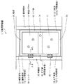
まず、本発明の可動開閉装置の実施形態について、図1及び図2を参照して説明する。
図1は、本実施形態の可動開閉装置の外観構成を示す正面図、図2は、ヒンジ部周辺を拡大して図示した断面図(図1のA−A断面図)である。
First, an embodiment of the movable opening and closing device of the present invention will be described with reference to FIGS. 1 and 2.
FIG. 1 is a front view showing an external configuration of the movable switchgear according to the present embodiment, and FIG. 2 is a cross-sectional view (a cross-sectional view taken along line AA in FIG. 1) showing the vicinity of the hinge portion in an enlarged manner.
図1に示すように、可動開閉装置1は、ドア部(開閉部本体)10と、枠部材20と、ヒンジ30とを備えている。
ここで、ドア部10は、液晶パネル11と、ドア枠12とを有している。
液晶パネル(瞬間調光ガラス)11は、図4に示したように、液晶板、絶縁層、透明電極、板ガラスを積層して形成されている。なお、液晶パネルは従来公知の任意好適なものを用いることができる。このため、液晶パネルについての詳細な説明は省略する。
As shown in FIG. 1, the movable opening / closing device 1 includes a door portion (opening / closing portion main body) 10, a frame member 20, and a
Here, the door unit 10 includes a
As shown in FIG. 4, the liquid crystal panel (instant light control glass) 11 is formed by laminating a liquid crystal plate, an insulating layer, a transparent electrode, and a plate glass. In addition, a conventionally well-known arbitrary suitable liquid crystal panel can be used. For this reason, the detailed description about a liquid crystal panel is abbreviate | omitted.
ドア枠12は、ドア部10の枠組みや仕切りとなる部材であって、右縦枠と左縦枠からなる立て框(たてかまち)部13と、左右の立て框部13を橋渡しする桟(さん)部14とを有している。
なお、このドア枠12は、立て框部13と桟部14だけで構成することに限るものではなく、例えば二以上の桟部14を橋渡しする組子(くみこ)部を含めることができる。そして、これら立て框部13,桟部14,組子部によって囲まれたところに液晶パネル11が嵌め込まれる。
The door frame 12 is a member that serves as a frame or a partition of the door unit 10, and is a bridge that bridges the vertical rack portion 13 composed of a right vertical frame and a left vertical frame, and the left and right vertical rod sections 13. San)
In addition, this door frame 12 is not restricted to comprising only the standing-up part 13 and the
立て框部13は、上述したように右縦枠と左縦枠とを有しているが、これらのうちヒンジ部30が取り付けられる方が内框部材13−1、他方が外框部材13−2となる。
内框部材13−1は、図2に示すように、内部が空洞になった部分があり、この空洞部には二次変圧器(昇圧器)43や操作スイッチ44などが取り付けられている。これら二次変圧器43や操作スイッチ44の詳細については後述する。
また、内框部材13−1は、液晶パネル11が嵌め込まれる側面に嵌合用切欠13−11(又は、嵌合用凹部)が形成されている。この嵌合用切欠13−11に液晶パネル11を嵌合させる場合、切欠13−11の端部と液晶パネル11との間には緩衝・封止ゴム13−12がはめ込まれる。これにより、液晶パネル11が固定するとともに、空洞部にゴミや水滴等が入り込むのを阻止できる。
As described above, the vertical rod 13 has the right vertical frame and the left vertical frame. Of these, the inner rod member 13-1 is attached to the
As shown in FIG. 2, the inner flange member 13-1 has a hollow portion, and a secondary transformer (boost) 43, an
Further, the inner collar member 13-1 has a fitting notch 13-11 (or a fitting recess) formed on a side surface into which the
枠部材20は、ドア部10を支持する枠である。この枠部材20は、縦枠部材21,22と鴨居部材23とを有しており、一の縦枠部材21にはヒンジ30が取り付けられている。このヒンジ30が取り付けられた縦枠部材(ヒンジ枠部材)21は、内部が空洞になった部分があり、この空洞部に一次変圧器41が取り付けられている。
The frame member 20 is a frame that supports the door unit 10. The frame member 20 includes
なお、一次変圧器41は、ヒンジ枠部材21の外部に取り付けることもできる。外部に取り付けるとは、ヒンジ枠部材21の側面に直接取り付けることと、ヒンジ枠部材21からは離間しているがヒンジ枠部材21の近くに取り付けることとを含む。このように一次変圧器41をヒンジ枠部材21の外部に取り付ける場合であって、ドア部10が浴室などの水場に設置されるときは、一次変圧器41は防水型とすることが望ましい。
The primary transformer 41 can also be attached to the outside of the
この一次変圧器41は、外部からの電源電圧を安全な低電圧に降圧する絶縁性の高い変圧器である。具体的には、電源電圧(AC100V)を低電圧(24V)に変圧する。その低電圧の片側端子は、図3に示すように、ヒンジ枠部材21や内框部材13−1とともに接地されている。これにより、一次変圧器41の巻線間の絶縁劣化による漏電電流を大地に逃がすことができる。
また、一次変圧器14として絶縁トランスを用いることで、液晶パネル11を雷サージから守ることができる。
The primary transformer 41 is a highly insulating transformer that steps down the power supply voltage from the outside to a safe low voltage. Specifically, the power supply voltage (
Further, by using an insulating transformer as the
可撓電線42は、一部が、一次変圧器41の低電圧側と二次変圧器43の低電圧側とを接続する電線であって、ヒンジ部(ヒンジ30の付近)で曲げ伸ばし自在に配置されている。
また、可撓電線42は、他の一部が、一次変圧器41の低電圧の片側端子から引き出された電線であって、弛みをもたせてドア部10の内框部材13−1の内部に引き込まれている。この引き込み線によって、内框部材13−1が接地される。
A part of the
The other part of the flexible
二次変圧器43は、可撓電線42を介して送られてきた低電圧を、液晶パネル11が作動するに必要な電圧に昇圧する。具体的には、二次変圧器43は、低電圧(24V)を例えば100Vに変圧する。
このように、二次変圧器43の高電圧出力を浮遊的に液晶パネル11に供給することで、さらに安全性を高めることができる。しかも、高電圧型液晶パネルを使用できるため、不透明性が高くなり、十分にプライバシーを守ることができる。
The
Thus, by supplying the high voltage output of the
なお、二次変圧器43は、図2においては、内框部材13−1の内部に取り付けられているが、内部に限るものではなく、外部に取り付けることもできる。ここで外部に取り付けるとは、内框部材13−1の側面に直接取り付けることと、内框部材13−1からは離間しているが内框部材13−1の近くに取り付けることとを含む。このように二次変圧器43を内框部材13−1の外部に取り付ける場合であって、ドア部10が浴室などの水場に設置されるときは、二次変圧器43は防水型とすることが望ましい。
In addition, although the
操作スイッチ44は、液晶パネル11の透明/不透明を切り換えるスイッチであって、図3に示すように、二次変圧器43の低電圧側に接続されている。この操作スイッチ44の操作ボタン44−1は、内框部材13−1の外側に突出していることから、利用者が室内から操作することができる。
The
次に、本実施形態の可動開閉装置の動作について、図2を参照して説明する。
操作スイッチ44がOFFのときは、液晶パネル11は不透明となっている。
操作スイッチ44がONに切り換えられると、一次変圧器41が、電源電圧(AC100V)を低電圧(24V)に変圧して出力する。この低電圧(24V)は、可撓電線42を介して二次変圧器43に与えられる。
二次変圧器43では、その低電圧(24V)を、液晶パネル11が動作する電圧(100V)に変圧して出力する。この出力された電圧(100V)が与えられて、液晶パネル11が透明になる。
Next, the operation of the movable opening / closing device of this embodiment will be described with reference to FIG.
When the
When the
In the
以上説明したように、本実施形態の可動開閉装置によれば、ヒンジ部を通す電圧を感電の危険がない低電圧とすることで、安全性を保つことができる。
また、一次変圧器の低電圧の片側を接地することにより、一次変圧器の巻線間の絶縁劣化による漏洩電流を大地に逃がすことができる。
さらに、二次変圧器の高電圧を浮遊的に液晶パネルに供給することで、三重の安全性を有することができる。
As described above, according to the movable opening / closing device of the present embodiment, safety can be maintained by setting the voltage passing through the hinge portion to a low voltage without risk of electric shock.
Also, by grounding the low voltage side of the primary transformer, leakage current due to insulation deterioration between the windings of the primary transformer can be released to the ground.
Furthermore, triple safety can be achieved by supplying the high voltage of the secondary transformer to the liquid crystal panel in a floating manner.
以上、本発明の可動開閉装置の好ましい実施形態について説明したが、本発明に係る可動開閉装置は上述した実施形態にのみ限定されるものではなく、本発明の範囲で種々の変更実施が可能であることは言うまでもない。
例えば、上述した実施形態では、開閉部本体の例としてドア部を挙げたが、開閉部本体はドア部に限るものではなく、ヒンジにより開閉可能な建具、例えば窓などを含むことができる。
The preferred embodiment of the movable switchgear according to the present invention has been described above. However, the movable switchgear according to the present invention is not limited to the above-described embodiment, and various modifications can be made within the scope of the present invention. Needless to say.
For example, in the above-described embodiment, the door portion is described as an example of the opening / closing portion main body. However, the opening / closing portion main body is not limited to the door portion, and can include a fitting such as a window that can be opened and closed by a hinge.
また、液晶パネルの電源は、一般家庭用電源を用いることができるが、これに限るものではなく、例えば、電池電源を用いることもできる。
さらに、上述した実施形態では、昇圧器の例として二次変圧器を挙げたが、昇圧器は二次変圧器に限るものではなく、例えば、半導体素子を用いたインバータ昇圧回路で構成することもできる。
また、液晶パネルは、電圧を印加した状態でスイッチをOFFにすると、この液晶パネル内に電荷がしばらく残留してしまって瞬時に不透明にならないという問題がある。そこで、残留電圧を放電するための回路を接続することもできる。
Moreover, although the power supply of a liquid crystal panel can use a general household power supply, it is not restricted to this, For example, a battery power supply can also be used.
Further, in the above-described embodiment, the secondary transformer is exemplified as the booster. However, the booster is not limited to the secondary transformer, and may be configured by an inverter booster circuit using a semiconductor element, for example. it can.
Further, the liquid crystal panel has a problem that if the switch is turned off in a state where a voltage is applied, the electric charge remains in the liquid crystal panel for a while and does not become opaque immediately. Therefore, a circuit for discharging the residual voltage can be connected.
本発明は、液晶パネルの電源供給回路に関する発明であるため、液晶パネルが使用される建築物や装置などに利用可能である。 Since the present invention relates to a power supply circuit for a liquid crystal panel, the present invention can be used for a building or an apparatus in which the liquid crystal panel is used.
1 可動開閉装置
10 ドア部(開閉部本体)
11 液晶パネル
12 ドア枠
13 立て框部
14 桟部
20 枠部材
21 縦枠部材(ヒンジ枠部材)
22 縦枠部材
23 鴨居部材
30 ヒンジ
41 一次変圧器
42 可撓電線
43 二次変圧器(昇圧器)
44 操作スイッチ
1 Movable opening / closing device 10 Door part (main part of opening / closing part)
DESCRIPTION OF
22 Vertical frame member 23
44 Operation switch
Claims (3)
前記枠部材の内部又は外部に取り付けられた一次変圧器と、
前記開閉部本体の内部又は外部に取り付けられた昇圧器と、
前記一次変圧器と前記昇圧器とを接続する可撓電線と、
前記液晶パネルの透明/不透明を切り換える操作スイッチとを備え、
前記一次変圧器は、入力した電源電圧を低電圧に変圧し、
前記昇圧器は、前記一次変圧器からの前記低電圧を昇圧して前記液晶パネルに供給し、
前記可撓電線にかかる電圧を、前記低電圧とし、
前記操作スイッチが、前記一次変圧器と前記昇圧器との間であって、前記昇圧器の低電圧側に接続された
ことを特徴とする可動開閉装置。 A movable opening / closing device comprising an opening / closing part main body having a liquid crystal panel, a frame member supporting the opening / closing part main body, and a hinge for attaching the opening / closing part main body to the frame member so as to be opened and closed,
A primary transformer attached inside or outside the frame member;
A booster attached to the inside or outside of the opening / closing part body;
A flexible electric wire connecting the primary transformer and the booster ;
An operation switch for switching between transparent and opaque of the liquid crystal panel,
The primary transformer transforms the input power supply voltage to a low voltage,
The booster boosts the low voltage from the primary transformer and supplies the boosted voltage to the liquid crystal panel .
The voltage applied to the flexible wire is the low voltage,
The movable switchgear characterized in that the operation switch is connected to the low voltage side of the booster between the primary transformer and the booster .
ことを特徴とする請求項1記載の可動開閉装置。 The movable switchgear according to claim 1, wherein the low voltage side of the primary transformer is grounded together with the frame member and / or the switch body.
ことを特徴とする請求項1又は2記載の可動開閉装置。The movable opening and closing device according to claim 1 or 2.
Priority Applications (1)
| Application Number | Priority Date | Filing Date | Title |
|---|---|---|---|
| JP2007111323A JP4926802B2 (en) | 2007-04-20 | 2007-04-20 | Movable switchgear |
Applications Claiming Priority (1)
| Application Number | Priority Date | Filing Date | Title |
|---|---|---|---|
| JP2007111323A JP4926802B2 (en) | 2007-04-20 | 2007-04-20 | Movable switchgear |
Publications (2)
| Publication Number | Publication Date |
|---|---|
| JP2008266994A JP2008266994A (en) | 2008-11-06 |
| JP4926802B2 true JP4926802B2 (en) | 2012-05-09 |
Family
ID=40046843
Family Applications (1)
| Application Number | Title | Priority Date | Filing Date |
|---|---|---|---|
| JP2007111323A Expired - Fee Related JP4926802B2 (en) | 2007-04-20 | 2007-04-20 | Movable switchgear |
Country Status (1)
| Country | Link |
|---|---|
| JP (1) | JP4926802B2 (en) |
Cited By (1)
| Publication number | Priority date | Publication date | Assignee | Title |
|---|---|---|---|---|
| JPWO2015016154A1 (en) * | 2013-07-29 | 2017-03-02 | 九州ナノテック光学株式会社 | Opening and closing tool |
Families Citing this family (4)
| Publication number | Priority date | Publication date | Assignee | Title |
|---|---|---|---|---|
| JP6065251B2 (en) * | 2010-07-05 | 2017-01-25 | パナソニックIpマネジメント株式会社 | Partition |
| JP5721253B2 (en) * | 2010-08-26 | 2015-05-20 | 八和エレック株式会社 | Electric shock prevention device for floor-operated overhead crane |
| JP6043520B2 (en) * | 2012-06-27 | 2016-12-14 | 株式会社アルファ | Wiring device and wiring structure |
| CN105607322A (en) * | 2016-01-04 | 2016-05-25 | 京东方科技集团股份有限公司 | Display panel, display device and driving method |
Family Cites Families (6)
| Publication number | Priority date | Publication date | Assignee | Title |
|---|---|---|---|---|
| JPH0826472B2 (en) * | 1988-08-01 | 1996-03-13 | 日本エレクトロプレイテイング・エンジニヤース株式会社 | Palladium plating solution |
| JPH08201788A (en) * | 1995-01-26 | 1996-08-09 | Pilot Corp:The | Liquid crystal light control device |
| JP2000134801A (en) * | 1998-10-21 | 2000-05-12 | Matsushita Electric Ind Co Ltd | Power supply system |
| JP4107011B2 (en) * | 2002-08-27 | 2008-06-25 | 松下電工株式会社 | Door unit |
| US6709145B1 (en) * | 2002-10-09 | 2004-03-23 | Shining Blick Enterprises Co., Ltd. | Exploding-like firework light |
| TWI236526B (en) * | 2004-09-15 | 2005-07-21 | Au Optronics Corp | Lamp driving device |
-
2007
- 2007-04-20 JP JP2007111323A patent/JP4926802B2/en not_active Expired - Fee Related
Cited By (1)
| Publication number | Priority date | Publication date | Assignee | Title |
|---|---|---|---|---|
| JPWO2015016154A1 (en) * | 2013-07-29 | 2017-03-02 | 九州ナノテック光学株式会社 | Opening and closing tool |
Also Published As
| Publication number | Publication date |
|---|---|
| JP2008266994A (en) | 2008-11-06 |
Similar Documents
| Publication | Publication Date | Title |
|---|---|---|
| JP4926802B2 (en) | Movable switchgear | |
| US10305273B2 (en) | Photovoltaic system and rapid shutdown method thereof | |
| US20130247954A1 (en) | Window or Door Having a Photovoltaic Module | |
| US8859884B2 (en) | Solar photovoltaic module safety shutdown system | |
| CN206035269U (en) | Plug -type light control glass door and window | |
| US20100300508A1 (en) | Photovoltaic system | |
| CN203858432U (en) | Electronic intelligent glass | |
| US8634169B2 (en) | Anti-lightning automatic switch for a satellite television receiver | |
| JP2006198564A (en) | Centrifuge | |
| KR101266963B1 (en) | Distributing board | |
| CN103532032A (en) | Novel power distribution box | |
| CN106132146A (en) | A kind of electromagnetic compatibility cabinet | |
| CN105116252A (en) | Test device for heating DC cable | |
| CN109713592A (en) | A kind of lightning protection shock-absorbing type power supply box | |
| CN210156728U (en) | Quick power supply and taking connecting device with load disconnecting link | |
| CN206674419U (en) | Electric cabinet of safe motor | |
| JP2016093028A (en) | In-board illuminating device for distribution panel | |
| KR20220049802A (en) | Smart glass | |
| CN212786468U (en) | Intelligent building security system | |
| CN108879378A (en) | The switchgear and its application method that a kind of substation is easy to use using combined type | |
| CN210669626U (en) | High-voltage live display locking device | |
| CN103426701B (en) | plug-in circuit protection device | |
| CN109585231B (en) | Waterproof dirt-proof overload protection switch | |
| CN205846471U (en) | Ring main unit | |
| JP3896320B2 (en) | Window with shutter |
Legal Events
| Date | Code | Title | Description |
|---|---|---|---|
| A621 | Written request for application examination |
Free format text: JAPANESE INTERMEDIATE CODE: A621 Effective date: 20100419 |
|
| A977 | Report on retrieval |
Free format text: JAPANESE INTERMEDIATE CODE: A971007 Effective date: 20110816 |
|
| A131 | Notification of reasons for refusal |
Free format text: JAPANESE INTERMEDIATE CODE: A131 Effective date: 20111011 |
|
| A521 | Written amendment |
Free format text: JAPANESE INTERMEDIATE CODE: A523 Effective date: 20111209 |
|
| TRDD | Decision of grant or rejection written | ||
| A01 | Written decision to grant a patent or to grant a registration (utility model) |
Free format text: JAPANESE INTERMEDIATE CODE: A01 Effective date: 20120110 |
|
| A01 | Written decision to grant a patent or to grant a registration (utility model) |
Free format text: JAPANESE INTERMEDIATE CODE: A01 |
|
| A61 | First payment of annual fees (during grant procedure) |
Free format text: JAPANESE INTERMEDIATE CODE: A61 Effective date: 20120208 |
|
| FPAY | Renewal fee payment (event date is renewal date of database) |
Free format text: PAYMENT UNTIL: 20150217 Year of fee payment: 3 |
|
| R150 | Certificate of patent or registration of utility model |
Free format text: JAPANESE INTERMEDIATE CODE: R150 |
|
| R250 | Receipt of annual fees |
Free format text: JAPANESE INTERMEDIATE CODE: R250 |
|
| LAPS | Cancellation because of no payment of annual fees |