JP4926668B2 - Compressor - Google Patents
Compressor Download PDFInfo
- Publication number
- JP4926668B2 JP4926668B2 JP2006315334A JP2006315334A JP4926668B2 JP 4926668 B2 JP4926668 B2 JP 4926668B2 JP 2006315334 A JP2006315334 A JP 2006315334A JP 2006315334 A JP2006315334 A JP 2006315334A JP 4926668 B2 JP4926668 B2 JP 4926668B2
- Authority
- JP
- Japan
- Prior art keywords
- bone
- handle
- sledge
- instrument
- knob
- Prior art date
- Legal status (The legal status is an assumption and is not a legal conclusion. Google has not performed a legal analysis and makes no representation as to the accuracy of the status listed.)
- Active
Links
- 210000000988 bone and bone Anatomy 0.000 claims description 108
- 230000006835 compression Effects 0.000 claims description 39
- 238000007906 compression Methods 0.000 claims description 39
- 238000006073 displacement reaction Methods 0.000 claims description 18
- 238000004873 anchoring Methods 0.000 claims 2
- 239000012634 fragment Substances 0.000 description 33
- 206010017076 Fracture Diseases 0.000 description 31
- 208000010392 Bone Fractures Diseases 0.000 description 20
- 238000000034 method Methods 0.000 description 16
- 238000003780 insertion Methods 0.000 description 5
- 230000037431 insertion Effects 0.000 description 5
- 239000000463 material Substances 0.000 description 5
- 238000001356 surgical procedure Methods 0.000 description 5
- 238000010586 diagram Methods 0.000 description 3
- 229910001220 stainless steel Inorganic materials 0.000 description 3
- 239000010935 stainless steel Substances 0.000 description 3
- 206010010214 Compression fracture Diseases 0.000 description 1
- 229920002430 Fibre-reinforced plastic Polymers 0.000 description 1
- 229910000831 Steel Inorganic materials 0.000 description 1
- RTAQQCXQSZGOHL-UHFFFAOYSA-N Titanium Chemical compound [Ti] RTAQQCXQSZGOHL-UHFFFAOYSA-N 0.000 description 1
- 208000027418 Wounds and injury Diseases 0.000 description 1
- XAGFODPZIPBFFR-UHFFFAOYSA-N aluminium Chemical compound [Al] XAGFODPZIPBFFR-UHFFFAOYSA-N 0.000 description 1
- 229910052782 aluminium Inorganic materials 0.000 description 1
- 230000003466 anti-cipated effect Effects 0.000 description 1
- 239000000560 biocompatible material Substances 0.000 description 1
- 238000006243 chemical reaction Methods 0.000 description 1
- 230000006378 damage Effects 0.000 description 1
- 239000011151 fibre-reinforced plastic Substances 0.000 description 1
- 208000014674 injury Diseases 0.000 description 1
- 238000004519 manufacturing process Methods 0.000 description 1
- 239000007787 solid Substances 0.000 description 1
- 239000010959 steel Substances 0.000 description 1
- 229910052719 titanium Inorganic materials 0.000 description 1
- 239000010936 titanium Substances 0.000 description 1
Images


Classifications
-
- A—HUMAN NECESSITIES
- A61—MEDICAL OR VETERINARY SCIENCE; HYGIENE
- A61B—DIAGNOSIS; SURGERY; IDENTIFICATION
- A61B17/00—Surgical instruments, devices or methods, e.g. tourniquets
- A61B17/56—Surgical instruments or methods for treatment of bones or joints; Devices specially adapted therefor
- A61B17/58—Surgical instruments or methods for treatment of bones or joints; Devices specially adapted therefor for osteosynthesis, e.g. bone plates, screws, setting implements or the like
- A61B17/68—Internal fixation devices, including fasteners and spinal fixators, even if a part thereof projects from the skin
- A61B17/80—Cortical plates, i.e. bone plates; Instruments for holding or positioning cortical plates, or for compressing bones attached to cortical plates
- A61B17/8004—Cortical plates, i.e. bone plates; Instruments for holding or positioning cortical plates, or for compressing bones attached to cortical plates with means for distracting or compressing the bone or bones
- A61B17/8019—Cortical plates, i.e. bone plates; Instruments for holding or positioning cortical plates, or for compressing bones attached to cortical plates with means for distracting or compressing the bone or bones where the means are a separate tool rather than being part of the plate
-
- A—HUMAN NECESSITIES
- A61—MEDICAL OR VETERINARY SCIENCE; HYGIENE
- A61B—DIAGNOSIS; SURGERY; IDENTIFICATION
- A61B17/00—Surgical instruments, devices or methods, e.g. tourniquets
- A61B17/16—Bone cutting, breaking or removal means other than saws, e.g. Osteoclasts; Drills or chisels for bones; Trepans
- A61B17/17—Guides or aligning means for drills, mills, pins or wires
- A61B17/1728—Guides or aligning means for drills, mills, pins or wires for holes for bone plates or plate screws
Description
本発明は、骨折修復分野に関し、より詳しくは骨プレートとともに用いられる圧迫器に関する。 The present invention relates to the field of fracture repair, and more particularly to a compression device used with a bone plate.
長年、骨プレートおよび他の固定手段は、骨に形成された骨折を修復するため、医師および外科医に広く用いられてきた。このような骨折では、一般に、単一であった骨構造が2個以上の断片に分かれ、これら骨折の多くは、2つの別個の断片となる。基本的に、異なる骨断片を元の位置に戻し、断片をまたがって骨プレートを設置し、ねじやその他の固定手段を利用して断片のそれぞれにそのプレートを固定するのが一般的な慣行であった。これにより、異なる断片がカルシウム再沈着によって互いに再付着し、骨折片が元の骨構造に再形成される。この過程中、固定した骨プレートは、断片が元の位置に保持されるようにし、骨構造を一定レベルで支持することが望ましい。 For many years, bone plates and other fixation means have been widely used by physicians and surgeons to repair fractures formed in bone. In such fractures, generally a single bone structure is divided into two or more fragments, and many of these fractures become two separate fragments. Basically, it is common practice to return different bone fragments to their original position, place a bone plate across the fragments, and secure the plate to each of the fragments using screws or other securing means. there were. This causes the different pieces to reattach to each other by recalcification, and the fracture pieces re-form to the original bone structure. During this process, the fixed bone plate preferably supports the bone structure at a certain level so that the fragments are held in place.
上述の骨折により生じた骨断片の再結合方法は、長年広く用いられ、圧倒的に有利な結果をもたらしてきたが、まったく欠点がないというわけではない。例えば、単純骨折の修復方法は基本的に上述した通りだが、多くの骨折は単純とは程遠い。しばしば、長い骨等の骨折は、身体への他の傷害を伴い、異なる骨断片を元の位置に戻すこと、あるいは圧迫することを困難にする。そのため、医師または外科医は、骨折した骨の異なる断片を元の位置へ戻すことに苦心することが多い。 Although the method of recombining bone fragments produced by the above-mentioned fractures has been widely used for many years and has produced overwhelmingly advantageous results, it is not completely free of drawbacks. For example, a simple fracture repair method is basically as described above, but many fractures are far from simple. Often, fractures such as long bones are accompanied by other injuries to the body, making it difficult to return or compress different bone fragments. As a result, physicians or surgeons often struggle to return different pieces of fractured bone to their original positions.
そのため、骨折した骨断片の再設定あるいは圧迫を支援する骨プレートまたはその他の同様の装置とともに用いる圧迫器の必要性が存在する。 Thus, there is a need for a compression device for use with bone plates or other similar devices that assist in resetting or compressing a fractured bone fragment.
本発明の第1の態様は、第1の骨断片を第2の骨断片に対して移動させる方法である。この態様による方法は、第1および第2の骨断片に隣接して、かつ、これらをまたがって骨プレートを設置し、骨プレートの第1側を第1の骨断片に固定し、骨プレートに形成された穴に器具を位置決めし、カニューレ挿入された開口を通して前記器具及び第2の骨断片内へ細長い要素を配置し、第1方向と異なる第2方向へ器具の第2部分を移動させるために、器具の第1部分を第1方向へ移動させ、第1部分の移動により第2の骨断片を第1の骨断片に対して移動せしめ、骨プレートの第2側を第2の骨断片に固定する段階を含むことができる。前記骨プレートは、その中に形成された少なくとも3つの穴を含むことができる。前記スリーブは、前記の細長い要素と係合するためにカニューレ挿入され、前記スリーブの移動によって、前記の細長い骨要素を平行移動せしめる。この方法は、ねじ、釘、ボルト、ステープルからなる群から選択される固定手段の利用を含むことができる。細長い要素は、Kワイヤ(キルシュナー鋼線)、ドリル、ピン、ねじ、釘、ボルトからなる群から選択することができることに注意する。この方法は、第1の骨断片および第2骨断片を互いに向かって、あるいは互いから離れて移動するように、実行されることができる。ある実施形態では、この器具は、ハンドル、スレッジ、スリーブ及びノブを含むことができる。これら実施形態では、ノブの回転によって、ハンドルの長手方向の軸に垂直な方向に、スレッジとスリーブを移動することができる。 The first aspect of the present invention is a method of moving a first bone fragment relative to a second bone fragment. A method according to this aspect includes placing a bone plate adjacent to and across the first and second bone fragments, securing the first side of the bone plate to the first bone fragment, Position the instrument in the formed hole, place an elongate element through the cannulated opening and into the instrument and the second bone fragment, and move the second portion of the instrument in a second direction different from the first direction. The first part of the instrument is moved in the first direction, the movement of the first part causes the second bone fragment to move relative to the first bone fragment, and the second side of the bone plate is moved to the second bone fragment. A fixing step. The bone plate can include at least three holes formed therein. The sleeve is cannulated to engage the elongate element, and movement of the sleeve causes the elongate bone element to translate. The method can include the use of a securing means selected from the group consisting of screws, nails, bolts, staples. Note that the elongate element can be selected from the group consisting of K-wire (Kirschner steel wire), drill, pin, screw, nail, bolt. This method can be performed to move the first and second bone fragments toward or away from each other. In certain embodiments, the instrument can include a handle, a sledge, a sleeve, and a knob. In these embodiments, rotation of the knob can move the sledge and sleeve in a direction perpendicular to the longitudinal axis of the handle.
本発明の別の態様は、骨圧迫/変位器具である。ある実施形態では、この器具は、長手方向の軸を有するハンドルと、ハンドルの一部に挿入されるスレッジと、ハンドルに接続されたノブとを含み、スレッジは、ハンドルに対して可動である。ノブの移動によって、ハンドルに対してスレッジを移動せしめる。この移動は、ハンドルの長手方向の軸に垂直な方向でよい。この器具は、ハンドルとスレッジを通して挿入されたスリーブを含むこともできる。ハンドルは、スレッジを受けるための切り欠き部分と、スリーブを受けるための通路の第1および第3部分とを含むことができる。さらに、スレッジは、スリーブを受けるための通路の第2部分を含むことができる。スリーブは、通路の第1および第3部分内を移動する大きさでよい。また、スリーブは、その中を通って細長い要素を受けるためにカニューレ挿入される。他の実施形態では、ノブは、ハンドルに螺合され、器具は、ノブに螺合されたナットを含むことができる。また、スレッジは、ハンドルの少なくとも1個の突起と協働する少なくとも1個の溝を含むことができる。ノブの回転は、ハンドルの長手方向の軸と垂直な方向にスレッジを平行移動せしめる。最後に、ハンドルは、骨プレートを通って形成された穴に挿入するための先端をさらに含むことができる。 Another aspect of the present invention is a bone compression / displacement instrument. In certain embodiments, the instrument includes a handle having a longitudinal axis, a sledge inserted into a portion of the handle, and a knob connected to the handle, the sledge being movable relative to the handle. The sledge is moved relative to the handle by moving the knob. This movement may be in a direction perpendicular to the longitudinal axis of the handle. The instrument can also include a sleeve inserted through the handle and sledge. The handle can include a notch portion for receiving a sledge and first and third portions of a passage for receiving a sleeve. In addition, the sledge may include a second portion of a passage for receiving the sleeve. The sleeve may be sized to move within the first and third portions of the passage. The sleeve is also cannulated to receive an elongated element therethrough. In other embodiments, the knob may be threaded onto the handle and the instrument may include a nut threaded onto the knob. The sledge may also include at least one groove that cooperates with at least one protrusion of the handle. The rotation of the knob translates the sledge in a direction perpendicular to the longitudinal axis of the handle. Finally, the handle can further include a tip for insertion into a hole formed through the bone plate.
本発明のさらに別の態様は、骨折修復キットである。この第3の態様のある実施形態によると、このキットは少なくとも1個の骨プレートと、少なくとも1個の細長い要素と、骨プレートと協働するよう適合された第1部分、第1部分に対して移動するよう適合された第2部分、及び、第1部分に対して第2部分の移動を生ぜしめるよう適合された第3部分をそれぞれ有する少なくとも1個の器具とを含む。細長い要素は、器具とともに配置可能で、器具の第2部分の移動は、細長い要素を器具の第1部分に対して移動させることが可能である。 Yet another embodiment of the present invention is a fracture repair kit. According to an embodiment of this third aspect, the kit comprises at least one bone plate, at least one elongate element, and a first part adapted to cooperate with the bone plate, the first part And at least one instrument each having a second portion adapted to move and a third portion adapted to cause movement of the second portion relative to the first portion. The elongate element can be disposed with the instrument and movement of the second portion of the instrument can cause the elongate element to move relative to the first portion of the instrument.
本発明の主題とその種々の利点は、添付図面に関して参照されている後述の詳細な説明を参考にして、より完全に理解することができる。
(詳細な説明)
The subject matter of the present invention and its various advantages can be more fully understood with reference to the following detailed description, taken in conjunction with the accompanying drawings, in which:
(Detailed explanation)
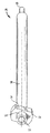
図面を参照すると、同様の参照番号は同様の要素を示し、図1において、圧迫器は、全体として参照番号10で指定される。圧迫器10は、好ましくは、US2005/0143742A1として公開されている共有の米国特許出願に開示されている骨プレートを含み、ただしこれに限定されない、多くの異なる骨プレート又は他の同様な器具と結合して使用可能であり、この米国特許の開示は、これにより、本願に引用して援用する。しかしながら、当技術分野で通常の技能を持つ人にとって明らかなように、本発明の圧迫器10は、多くの異なる骨プレートとともに利用されるように容易に修正できる。これについては下記に詳述する。図1および図2に最もよく示されているように、圧迫器10は、近位端12と遠位端14とを有する細長い構造にできる。圧迫器10は、外科医やその他の医療専門家が器具を把持して操作できる大きさおよび構成であることが望ましい。さらに、圧迫器10は、身体の切開やその他の開口に挿入できる大きさとすることができるが、これについては本発明を利用する方法に関連して下記にさらに詳述する。
Referring to the drawings, like reference numerals indicate like elements, and in FIG. 1, the compressor is designated generally by the
図3の分解図に最もよく示されているように、圧迫器10は、ハンドル16、スレッジ18、Kワイヤ・スリーブ20、ノブ22、ナット24を含む。これらの要素は、それぞれ図4から図8により詳しく示される。要素は、それぞれ互いと相互接続して、単一包含単位を形成することが望ましい。しかしながら、圧迫器10は、完全に組み立てられた形において、より少ない要素あるいはより多くの要素を含むこともできることが理解されるべきである。例えば、図3に示すように、圧迫器10は、さらにバネアセンブリ26を含み、これはスリーブ20が完全に組み立てられた器具10から落下することを防げる。これについては、圧迫器10の個別要素のそれぞれとして下記に詳述する。
As best shown in the exploded view of FIG. 3, the
図4を参照すると、ハンドル16は、圧迫器10の他の要素とは別に特に詳しく描かれている。この図および完全に組み立てられた圧迫器10を示す他の図に示すように、ハンドル16は、その細長い特質とともに、器具10に含まれる構造の大部分を提供する。実際、ハンドル16は、基本的に前述の近位端12と遠位端14の間を延びており、そのようなものとして、これら端部を図4に示す。ハンドル16は、管状構造であることが望ましく、遠位部分30、把持部分32、先端部分34の3個の別個部分を含む。遠位部分30は、ノブ22と協働するために、ねじ山がつけられた部分36(この協働は、図9に最もよく示される)と、スリーブ20の一部を固定するための矩形開口37(この協働は、図10aおよび図10bに最も良く示されている)を有することが望ましい。さらに、通路28の第1部分28aは、遠位部分30を通って延びる。把持部分32は、基本的に部分30および34に対して、より大きく及び/又は隆起した部分である。好適な実施形態では、把持部分32は、把持性改良のための対向する波形面38aおよび38bと、スレッジ18を受けてこれと協働するため、その中に延びる突起42a、42b、42c及び42dを有する切り欠き部分40を含む。最後に、先端部分34は、断面が円形であることが望ましく、プレート上の同様な大きさの穴と係合するための最も近位の先端44を含むことができる。さらに先端部分34は、中を通って延びる通路28の第3部分28cを含む。
With reference to FIG. 4, the
図5に示すように、スレッジ部分18は、第1の構造体部分46と、第2の構造体部分48とを有する単一の構造体であることが望ましく、第1および第2の構造体部分は、それぞれ実質的に矩形の断面形状を有する。さらに、第1の構造体46は、その一部が少なくとも一方向に沿ってスレッジ18の残余部分を超えて延びるように、第2の構造体48よりも幅広いことが望ましい。この幅又は大きさの相違により、動作中に器具10の他の要素と協働することができるが、これについては以下に詳述する。第2の構造体48は、4つの溝又はスロット50a、50b、50c及び50dを含むことが望ましく、これらは角度が付けられている、及び/又は、ハンドル16の突起42a、42b、42cおよび42dとの接合のために適合された角度が付けられた部分を含んでいる。最後に、スレッジ部分18は、中を延びる通路28の第2部分28bを含む。
As shown in FIG. 5, the
このように、通路28は、ハンドル16の遠位部分30を通って形成された第1の部分すなわち部分28aと、スレッジ18を通って形成された第2の部分すなわち部分28bと、ハンドル16の先端部分34を通って形成された第3の部分すなわち部分28cとを含む。その結果、完全に組み立てた器具10に、連続する通路28が形成される。
As such, the passageway 28 includes a first portion or
図6は、スリーブ20を詳細に示しており、これは、Kワイヤやその他の細長い要素上に嵌合するよう適合され、細長い要素は、骨本体などに埋め込まれるように適合されることが望ましい。スリーブ20は、ハンドル16とスレッジ部分18に形成された通路28内に嵌合するような大きさと構成の実質的に単一管状体であることが望ましい。さらに、スリーブ20は、スリーブと第1部分28aおよび第3部分28cとの間に所定量の空隙ができるが、スリーブと第2部分28bとの間には実質的に空隙ができないよう、通路28内に嵌合する大きさと構成とすることができる。そのため、スリーブ20は、通路28の第1部分および第3部分の直径よりやや小さく、実質的に部分28bの直径と同じ直径を持つ大きさである。
FIG. 6 shows the
図6に示すように、スリーブ20は、ハンドル16の前述の矩形開口37に挿入される肩部分52を含むことができる。スリーブ20と通路28の部分28aおよび28cとの間の空隙と比較して、矩形開口37と肩部分52の間に同一あるいは異なる空隙量を与えるために、この矩形開口37は、肩部分52より大きくなるような寸法とすることができる。前述のバネアセンブリ26は、スリーブ20が完全に組み立てられた器具10から落下するのを防ぐために、肩部分52の開口54に挿入することができる。動作中に、バネアセンブリ26は、矩形開口37の一部に力を加え、スリーブ20がそこから不意に移動したり、外れたりすることを防ぐ。スリーブ20の残りは、同様の大きさの管状部分56および58と、より小さい直径で、一段小さい管状部分60を含む。スリーブ通路62(図9の断面図に最もよく示されている)は、スリーブ20を貫いて伸びている。図9に示すように、この通路は、異なる大きさの部分62aと62b、あるいは、どちらか一方の1つの大きさの部分を含むことができる。好適な実施形態では、スリーブ通路62は、Kワイヤ等がその中に嵌入する大きさである。しかしながら、通路62は、その中にロッド、釘、ねじ等を挿入できるようなサイズとすることもできる。
As shown in FIG. 6, the
図7および図8は、ノブ22とナット24をそれぞれより詳しく示している。ノブ22は、外科医または術者によって容易に把持および回転ができるよう、把持面64を有する管状構造とすることができる。ノブ22は、ハンドル16の遠位部分30上に嵌合する大きさおよび構成であることが望ましい。さらに詳しくは、ノブ22は、ハンドル16のねじ山面36と螺合する内部ねじ山面66を含むことができる。さらに、ノブ22は、ナット24と螺合する外部ねじ山面68を含むこともできる。ナット24は、ノブ22の前記外部ねじ山面68と螺合する内部ねじ山面70を有する管状構造としてよい。基本的に、ナット24は器具10の容易な組み立ておよび分解を可能にする。
7 and 8 show the
器具10の上記要素は、その大きさおよび構造を含めて、特定の構成において変化することに注意する。例えば、スリーブ20は、骨に挿入する様々な細長い要素上を摺動するために、異なる大きさとすることができる。さらに器具10の各種要素は、多くの様々な種類の材料で構成できることに注意する。例えば、器具10の構成要素は、ステンレススチールやポリマー材料等、患者の身体への挿入に適した生体適合性材料で構成することができる。チタン、アルミニウムおよび繊維強化プラスチックも利用できる。しかしながら、所定の構成要素を所定の一種類の材料で構成し、その他の要素を第2の異なる種類の材料で構成できる点にも注意する。例えば、ハンドル16は、製造を容易にするためポリマー材料で構成するが、一方、スリーブ20は、骨に挿入するステンレススチールの細長い要素との満足な利用を保証するために、ステンレススチールで構成できる。
Note that the above elements of the
圧迫器10の組み立て方法を以下に述べる。ただし、異なる順序や異なる方法などでの組み立てを含む、異なる組み立て方法を保証していることが理解されるべきである。最初に、スレッジ18がハンドル16の切り欠き部分40に挿入され、これにより、突起42a、42b、42c及び42dが溝50a、50b、50c及び50dの中に届く。その後、スリーブ20を通路28の3つの部分28a、28bおよび28cのすべての中に、それらを通して滑り込ませ、スリーブ20の肩部分52が、ハンドル16の矩形開口37に挿入される。前述のように、バネアセンブリ26は、矩形開口37と係合され、スリーブ20がハンドル16から不意に外れたり移動したりすることを防ぐこともできる。このようにしてスリーブ20を取り付ける。次に、ノブ22をハンドル16の遠位部分30の上に滑り込ませ、その内部ねじ山面66を遠位部分30の外部ねじ山部分36と螺合させる。ノブ22がハンドル16に正しく配置されると、ノブ22の面68の端面68aがスレッジ18の矩形本体46と接触することに注目する。このようにして、矢印B(図9から図10b)で示す方向へのノブ22の平行移動がスレッジ18に与えられる。最後に、ナット24をハンドル16の先端部分34と把持部分32の上に滑り込ませ、ノブ22と螺合させる。すなわち、ナット24の内部ねじ山面70は、ノブ22の外部ねじ山面68と螺合する。さらに、スレッジ18の矩形構造体46は、ノブ22の端面68aとナット24と間でクランプされ、ノブ22とナット24の矢印B(図9から図10b)で示すのとは反対方向への平行移動は、スレッジ18を同じ方向に移動させる。ナット24は、器具10の他の構成要素又は他の構成要素の一部と接触しないことに注意しなければならない。そのため、ノブ22は、自由に回転でき、また、少なくとも部分的にハンドル16に沿って平行移動または移動することが可能である。この動作について後で詳しく述べる。いずれにせよ、ナット24を取り付けたら、器具10の各種構成要素は、本質的にその組み立て位置にロックされる。圧迫器10の要素の最終的相互接続または組立てを図9の断面図と図10aおよび図10bの部分断面図に明確に示す。
A method for assembling the
動作中、ノブ22の時計回りの回転(図9から図10bの矢印Aで示す)は、ノブ22とナット24の両方に、矢印B(図9から図10b)で示す方向への器具10の長手方向の軸に沿った移動を生じさせる。ノブ22の一部がスレッジ18の一部に接するので、ノブ22のこの長軸方向の移動が、スレッジ18に同様の長軸方向の移動を生じさせ、角度付き溝50a、50b、50c及び50dの突起42a、42b、42c及び42dに沿った移動を引き起こし、これにより、スレッジ18が、開放切り欠き部分40の一方から他方へ平行移動する。図で示すと、この平行移動は、図9において紙面に入ったり紙面から出たりする移動、および、図10aと図10bで示されるような左側と右側の間の移動(図10aと図10bにおいて矢印Cで示される)として最も適切に示される。スリーブ20は、スレッジ18の通路部分28b内にきつく配置され、通路部分28aと28c内ではわずかに移動できるため、スリーブ20はスレッジ18とともに移動できる。そのため、ノブ22の回転運動は、最終的にスリーブ20へ平行移動を生じさせ、同時にスリーブ通路62内に収納されたあらゆる細長い構造物の平行移動を生じさせる。これについてはさらに後述する。
In operation, clockwise rotation of the knob 22 (indicated by arrow A in FIGS. 9-10b) causes both the
外科的な処置において、圧迫器10によって与えられる回転移動から平行移動への前記変換は、骨折の修復または圧迫において外科医を支援するために用いられる。前述した通り、圧迫器10は、図10aおよび図10bに示す骨プレート80を含む、多くの様々な種類の骨プレートあるいはその他の種類の装置とともに用いることができる。図10aおよび図10bに示す実施形態では、骨プレート80は、骨100への取付けを可能にするための少なくとも2個のねじ穴82および84と、圧迫器10の先端44を中に挿入可能にするための穴86を含む。3個の穴は同様の大きさであるか、異なる大きさまたは直径を持つことができる点に注意する。例えば、ある実施形態の骨プレートは楕円穴、スロット、ねじ山付き穴(例えば一軸ネジ)等を有することができる。さらにプレート外への取付けも可能性としてあることに注意する。図10aに示すように、骨プレート80は、患者の皮膚の切開部分を通して骨100の上に置くことができ、これにより骨プレート80は、骨折106によって生じた骨断片102および104にまたがるようになる。その後、第1のねじあるいはその他の種類の留め具手段を穴84に挿入し、骨プレート80の穴84の側のみが骨100に固定される。その結果、断片102のみがプレート80に対して移動可能となる。
In surgical procedures, the conversion from rotational movement to translation provided by the
前述したように骨プレート80の一方の側を骨100に固定すると、圧迫器10の先端44は、切開部分を通じて穴86に挿入される。かかる切開時またはその前に、ノブ22は、反時計回り方向に出来る限り回転される。これによって、スレッジ18を出来る限り一方の側の奥に配設することができる。さらに図10aおよび図10bに示すように、器具10は、スレッジ18が骨折106から可能な限り遠くにセットされるように、穴86内で正しい方向に向けられ、あるいは位置決めされ、これによりスレッジ18のあらゆる移動は、骨折を圧迫するか閉じることになる。器具10をこの位置にして、Kワイヤ108あるいは同様な器具は、器具10のカニューレ挿入された構成要素を通じて、図10aに示すように、骨100の断片102に挿入される。この中に示すように、器具10のこのような位置、より詳しくはスレッジ18とスリーブ20は、Kワイヤ108を穴86の一方の側(骨折106からさらに離れた穴86の側)に位置決めする。Kワイヤ108は、バイコーティカルに挿入することができる。
As described above, when one side of the bone plate 80 is fixed to the
前述したように、器具10が骨プレート80の穴86に挿入され、Kワイヤ108が器具10を通って骨断片102に挿入された後、外科的な処置の次の段階、すなわちノブ22の回転が実行される。図10aおよび図10bに示されるように、ハンドル16は、この回転中、器具10の向きを維持するよう保持される。前述のように、ノブ22の回転は、スレッジ18とスリーブ20の平行移動を発生させる。これにより、ノブ回転段階の実行は、これら構成要素とKワイヤ108を図10bに示す位置へ移動させる。その結果、断片102もKワイヤ108とともに移動し、これにより、骨折106を圧迫し、骨100を骨折前の状態に戻すことができる。このとき、第2のねじあるいは他の種類の留め具手段を穴82に挿入し、骨プレート80は、骨100の両断片に固定され、断片102と104は互いに対してもはや移動できない。最後に、器具10とKワイヤ108は取り外される。Kワイヤ108によって骨100に形成された穴は、あけたままにするか、他のねじが穴86を通って装入される。この外科処置の結果、断片102および104は、その最終位置(図10b)に留まり、再石灰化して1つの堅固な骨を形成する。
As previously described, after the
前述の外科処置は、追加的及び/又は異なる段階を含むことが理解されるべきである。例えば、穴86への器具10の挿入後に、Kワイヤ108を挿入する代わりに、器具10が穴86に挿入される前に、Kワイヤは、骨100に挿入され得る。この例では、器具10は、Kワイヤを覆うように挿入され、穴86内へ挿入される。別の例として、骨100にKワイヤ108を移植するのではなく、他の種類の要素または構造体が骨に挿入される可能性がある(ドリル、ピン、ボルト、釘、タップ、ねじ山付きピン等)。明らかに、器具10は、利用する骨固定構造によって異なる大きさにできる。さらに、器具10は、断片を圧迫するのとは反対に、これを変位させるために用いることができる。器具10をこのように利用する間、外科医またはその他の医療専門家は、ノブ22の回転が骨断片の1個を互いから離れて移動するように、器具10および細長い要素(例えばKワイヤ108)を位置決めできる。これは、骨の一部に圧迫骨折等が発生した場合に有効である。そのため、当技術分野で通常の技能を持つ人にとって明白であるように、圧迫/変位の方向は、器具10およびその各種構成要素を異なる向きにすることによって調整される。図10aおよび図10bは、細長い骨の単純で直線的な骨折を示しているが、多くの骨折はこのように単純ではない。このような非単純骨折では、外科医や他の医療専門家は、骨を継ぎ直す過程の間、骨断片を複数の方向に移動させる必要がある。このような状況において、器具10の向きは状況に応じて変更可能である。
It should be understood that the aforementioned surgical procedures include additional and / or different stages. For example, instead of inserting the
さらに骨プレートは、圧迫/変位に先立って、圧迫/変位を生じさせる両断片に取り付けられる。この状況において、移動される骨断片を含む骨折線の側に細長い溝穴を持つ骨プレートが提供される。骨プレートは、この溝穴を介して固定手段(ねじや他の種類の留め具等)で移動可能な断片に取り付けられる。かかる固定手段またはねじは、この時点で完全に締め付けまたは固定される必要がないことが理解される。その後、器具10は、断片を移動させ、固定手段を溝穴に沿って動かすように操作される。所望の位置決めが達成された時点で、固定手段またはねじは、骨プレートを骨に恒久的に固定するために締め付けられる。さらに、別の固定手段がプレートを介して骨に挿入される。
In addition, the bone plate is attached to both pieces that cause compression / displacement prior to compression / displacement. In this situation, a bone plate is provided having an elongated slot on the side of the fracture line containing the bone fragment to be moved. The bone plate is attached to a fragment that can be moved by a fixing means (such as screws or other types of fasteners) through the slot. It will be appreciated that such securing means or screws need not be fully tightened or secured at this point. The
さらに、器具10は、1箇所以上の骨折のある骨を修復するために、1個あるいは複数の骨プレートとの接続において使用されることに注意すべきである。例えば、図10aおよび図10bに示す構成を用いると、骨折106のいずれかの側に、第2の骨折が位置する場合がある。第1の骨折106が前記工程あるいは他の類似した工程で修復されると、器具10は、第2骨折を圧迫するために適した位置にある別の穴に移動される。その後、外科医や他の医療専門家は、第2骨折を圧迫および固定する前記段階を単純に再実行する。この手順は、骨折した箇所の数あるいは骨折の種類に依存して、何度も繰り返される。相互の位置に関する骨折の詳細は大きく異なるため、かかる変動への対処を助けるために、骨プレートは、容易に穴あけができるように適合あるいは設計されており、これにより前述した段階を実行するために適した多数の穴を、各々の穴が所望の大きさと所望の位置であるように用意することができる。これらは、当技術分野で通常の技能を持つ人に完全に理解されるであろう。
Furthermore, it should be noted that the
さらに、器具10は前述した構成と異なる構成とすることができる。例としてスリーブ20を省略し、Kワイヤを収納するようにスレッジ18を変更可能である。別の例では、スレッジ18に平行移動を起こさせるために、ノブ22が回転力とは異なる力がかかるように設計され得ることに注意すべきである。1つの予想される実施形態では、ノブにかかる下向きの力がスレッジ18に所望の平行移動を与えるようなノブ22を用意することが可能である。
Furthermore, the
最後に図11は、第2の実施形態の器具200を示す。前述した器具10と同様に、器具200は、多くの類似要素を含むが、200番台の参照番号で指定される。例えば、器具200は、ハンドル216、スレッジ部分218、Kワイヤスリーブ220、ノブ222、及び、ナット224を含む。これらの要素は、器具200も類似機能を実行できるように、器具10と同じ様式で操作するのが望ましい。しかしながら、骨プレートや他の類似品と協働するのではなく、器具200は、第2の細長い要素と係合するために、中を通って形成された穴227を有する横方向部分225を含む。器具10の動作と同様に、動作中におけるノブ222の時計回りの回転(図11において矢印A’で示す)は、スリーブ220を最終的に横方向部分225および穴227に向かうか、逆方向に移動させることが望ましい。
Finally, FIG. 11 shows the
器具200を利用した1つの外科処置において、骨プレートあるいは他の類似品を使用するのではなく、外科医は器具200を単純に骨100に隣接して設置し、これによりスリーブ218が断片102上に静止し、穴227が断片104上に静止する。その後、Kワイヤ(それぞれ、108と109)の骨断片102および104への挿入を案内するために、外科医は、スリーブ218の管と穴227を利用する。前述のような他の細長い要素を利用してもよいことに注意すべきである。さらに、かかる細長い要素は、骨100に隣接して器具200を設置する前に挿入できることに注意すべきである。細長い要素108と109の双方が骨100に挿入され、器具200がこれらと係合されると、器具10に関連して述べた操作と同様な器具の操作は、断片102を断片104の方向へ移動させるはずである。このように、骨プレートあるいは類似品を使用せずに、器具10で達成された結果と同じ結果が器具200で達成される。
In one surgical procedure utilizing the
本発明は、特定の実施形態に関連して記載されているが、これらの実施形態は単に原理の実例であり、本発明の応用であることが理解されるべきである。したがって、説明に役立つ実施形態に対する多くの変形が可能であり、添付した特許請求の範囲で定義された本発明の範囲から逸脱せずに、他の構成が考案され得ることが理解されるべきである。 Although the invention has been described with reference to particular embodiments, it is to be understood that these embodiments are merely illustrative of the principles and are applications of the invention. Accordingly, it should be understood that many variations to the illustrative embodiments are possible, and that other configurations may be devised without departing from the scope of the invention as defined in the appended claims. is there.
10 圧迫器
12 近位端
14 遠位端
16 ハンドル
18 スレッジ
20 スリーブ
22 ノブ
24 ナット
26 バネアセンブリ
28 通路
28a 通路の第1部分
28b 通路の第2部分
28c 通路の第3部分
30 遠位部分
32 把持部分
34 先端部分
36 ねじ山面
37 矩形開口
38a 波形面
38b 波形面
42a 突起
42b 突起
42c 突起
42d 突起
44 最先端
46 矩形構造体
50a 溝
50b 溝
50c 溝
50d 溝
52 肩部分
56 管状部分
58 管状部分
62 スリーブ通路
62a 部分
62b 部分
66 内部ねじ山面
68 外部ねじ山面
68a 端面
70 内部ねじ山面
80 骨プレート
82 ねじ穴
86 穴
100 骨
102 骨断片
104 骨断片
106 骨折
108 Kワイア
200 器具
218 スリーブ
220 Kワイアスリーブ
222 ノブ
224 ナット
225 横方向部分
227 穴
10
Claims (13)
前記ハンドル(16)の一部(32)に配置され、前記ハンドル(16)に関して移動可能であるスレッジ(18)と、
前記ハンドル(16)に接続されたノブ(22)と
を備え、
前記ノブの移動によって、前記ハンドルに関する前記スレッジの移動を生ぜしめる骨圧迫/変位器具(10)であって、
前記スレッジ(18)が、ハンドル(16)の長手方向の軸に平行な細長い骨固定要素(108)を受ける手段を含み、
前記ノブ(22)の運動により、前記ハンドル(16)の長手方向の軸に垂直な方向に、前記スレッジ(18)が平行移動する
ことを特徴とする骨圧迫/変位器具。 A handle (16) having a longitudinal axis;
Wherein disposed on a portion (32) of the handle (16), and sledge (18) is movable with respect to said handle (16),
A knob (22) connected to the handle (16) ;
A bone compression / displacement instrument (10) wherein movement of the knob causes movement of the sledge relative to the handle ;
Said sledge (18) comprises means for receiving an elongated bone anchoring element (108) parallel to the longitudinal axis of the handle (16);
A bone compression / displacement instrument, characterized in that the movement of the knob (22) translates the sledge (18) in a direction perpendicular to the longitudinal axis of the handle (16) .
少なくとも1個の細長い要素と、
請求項1〜12のいずれかに記載の骨圧迫/変位器具と、
を含む骨折修復キット。
At least one bone plate (80) ;
At least one elongated element;
A bone compression / displacement instrument according to any of claims 1-12;
Including fracture repair kit.
Applications Claiming Priority (2)
| Application Number | Priority Date | Filing Date | Title |
|---|---|---|---|
| US11/285,808 | 2005-11-23 | ||
| US11/285,808 US7704257B2 (en) | 2005-11-23 | 2005-11-23 | Compression instrument |
Publications (2)
| Publication Number | Publication Date |
|---|---|
| JP2007144166A JP2007144166A (en) | 2007-06-14 |
| JP4926668B2 true JP4926668B2 (en) | 2012-05-09 |
Family
ID=37744791
Family Applications (1)
| Application Number | Title | Priority Date | Filing Date |
|---|---|---|---|
| JP2006315334A Active JP4926668B2 (en) | 2005-11-23 | 2006-11-22 | Compressor |
Country Status (7)
| Country | Link |
|---|---|
| US (1) | US7704257B2 (en) |
| EP (1) | EP1790302B1 (en) |
| JP (1) | JP4926668B2 (en) |
| CN (1) | CN101002695B (en) |
| AU (1) | AU2006236054B2 (en) |
| CA (1) | CA2568614C (en) |
| ES (1) | ES2556589T3 (en) |
Families Citing this family (10)
| Publication number | Priority date | Publication date | Assignee | Title |
|---|---|---|---|---|
| BR0318430B1 (en) * | 2003-08-08 | 2012-06-26 | clamping device. | |
| US20060015066A1 (en) * | 2004-05-17 | 2006-01-19 | Turieo Melanie J | Intraosseous infusion device |
| EP2397091B1 (en) * | 2007-11-02 | 2015-12-02 | Biomet C.V. | Elbow fracture fixation system |
| US9060748B2 (en) * | 2009-03-18 | 2015-06-23 | Smith & Nephew, Inc. | Soft tissue manipulator assembly |
| WO2011031495A2 (en) * | 2009-08-25 | 2011-03-17 | K-Comp, Llc | Bone compression system |
| US10441317B2 (en) | 2016-10-26 | 2019-10-15 | SIGN Fracture Care International | Bone fixation system and method using a clamping instrument to guide fastener placement |
| WO2018223063A1 (en) * | 2017-06-01 | 2018-12-06 | Shawn Burke | Method and system for the reduction and fixation of bone segments |
| KR102086690B1 (en) * | 2018-02-13 | 2020-03-10 | 큐렉소 주식회사 | Surgical operation apparatus for medical screw, surgical robot using thererof and surgical method for using trereof |
| CN109009393A (en) * | 2018-07-24 | 2018-12-18 | 莆田学院附属医院(莆田市第二医院) | A kind of minimal invasion reduction of the fracture device |
| US11844556B2 (en) * | 2021-12-07 | 2023-12-19 | Arthrex, Inc. | Surgical reduction tools and methods for achieving bone compression |
Family Cites Families (59)
| Publication number | Priority date | Publication date | Assignee | Title |
|---|---|---|---|---|
| US1395587A (en) * | 1920-07-26 | 1921-11-01 | Mclachlan John | Cam-shaft remover |
| US1997466A (en) * | 1934-04-23 | 1935-04-09 | Harry Herschel Leiter | Surgical appliance |
| US2224480A (en) * | 1939-10-27 | 1940-12-10 | Kartarik Joseph | Centering device |
| US2301500A (en) * | 1940-05-31 | 1942-11-10 | Anderson Roger | Wire guiding device |
| CH373516A (en) | 1959-09-01 | 1963-11-30 | Maurice E Dr Med Mueller | Device for the surgical fixation of bone fragments in limbs |
| US3244170A (en) * | 1962-11-23 | 1966-04-05 | Robert T Mcelvenny | Compression type bone splint |
| US3386437A (en) * | 1966-01-14 | 1968-06-04 | Richard Mfg Company | Compression device for use with a bone fracture plate |
| USRE28841E (en) * | 1966-06-22 | 1976-06-08 | Synthes A.G. | Osteosynthetic pressure plate construction |
| USRE31628E (en) * | 1966-06-22 | 1984-07-10 | Synthes Ag | Osteosynthetic pressure plate construction |
| FR1538053A (en) * | 1967-08-18 | 1968-09-07 | Osteosynthesis plate combined with its key | |
| US3540322A (en) * | 1968-08-09 | 1970-11-17 | Carl E Swanson | Drill fixtures |
| US3709219A (en) * | 1970-11-27 | 1973-01-09 | W Halloran | Bone compression device |
| FR2210908A6 (en) | 1972-12-15 | 1974-07-12 | Emco Sa | |
| US3866607A (en) * | 1973-08-09 | 1975-02-18 | Environmental Sciences Corp | Bone fracture compression device and method of usage |
| SU594973A1 (en) | 1975-05-11 | 1978-02-28 | Shavgulidze Tamazi Sh | Wire-tensioning device |
| GB1571713A (en) * | 1976-04-21 | 1980-07-16 | Gil J L | Apparatus for use in the treatment of bone fractures |
| CH645264A5 (en) * | 1980-05-28 | 1984-09-28 | Straumann Inst Ag | FITTING WITH A PLATE AND SCREWS THAT FIX IT TO A BONE. |
| US4502160A (en) * | 1983-10-27 | 1985-03-05 | Dow Corning Wright | Adjustable length prosthetic joint implant |
| DE3701533A1 (en) * | 1987-01-21 | 1988-08-04 | Medi System Gmbh | OSTEOSYNTHESIS TOOLS |
| CN2036410U (en) * | 1988-07-30 | 1989-04-26 | 滁县地区第二人民医院 | External skeletal fixation device for tibia |
| FI82805C (en) * | 1988-12-23 | 1991-04-25 | Biocon Oy | EN POLYMER FIXERINGSKIVKONSTRUKTION FOER KIRURGISKT BRUK. |
| US5021056A (en) * | 1989-09-14 | 1991-06-04 | Intermedics Orthopedics, Inc. | Upper tibial osteotomy system |
| US5167665A (en) * | 1991-12-31 | 1992-12-01 | Mckinney William W | Method of attaching objects to bone |
| US5290281A (en) * | 1992-06-15 | 1994-03-01 | Medicon Eg | Surgical system |
| DE9216565U1 (en) * | 1992-12-04 | 1994-03-31 | Link Waldemar Gmbh Co | Device for connecting bone parts by means of a bone plate |
| IL105183A (en) * | 1993-03-28 | 1996-07-23 | Yehiel Gotfried | Surgical device for connection of fractured bones |
| US5364396A (en) * | 1993-03-29 | 1994-11-15 | Robinson Randolph C | Distraction method and apparatus |
| US5505733A (en) * | 1993-10-22 | 1996-04-09 | Justin; Daniel F. | Intramedullary skeletal distractor and method |
| US5788697A (en) * | 1994-02-24 | 1998-08-04 | Pioneer Laboratories, Inc. | Cable tensioning device |
| US5439465A (en) * | 1994-03-11 | 1995-08-08 | Tumibay; Delfin O. | Bone compression and distraction surgical tool |
| US5632747A (en) * | 1995-03-15 | 1997-05-27 | Osteotech, Inc. | Bone dowel cutter |
| US5634926A (en) * | 1995-04-25 | 1997-06-03 | Jobe; Richard P. | Surgical bone fixation apparatus |
| CA2158890C (en) * | 1995-09-22 | 2002-01-22 | John Runciman | Spherical washer for use with a bone screw |
| EP0770359A1 (en) * | 1995-10-05 | 1997-05-02 | Medicon e.G. Chirurgiemechaniker-Genossenschaft | Distraction device for bone segments |
| US5676667A (en) * | 1995-12-08 | 1997-10-14 | Hausman; Michael | Bone fixation apparatus and method |
| US5849012A (en) * | 1996-03-11 | 1998-12-15 | Abboudi; Shalom Y. | Surgical clamping assemblies and methods of use |
| US5976139A (en) * | 1996-07-17 | 1999-11-02 | Bramlet; Dale G. | Surgical fastener assembly |
| DE19637938A1 (en) * | 1996-09-17 | 1998-03-26 | Juergen Harms | Bone plate |
| ES2299202T3 (en) | 1997-02-11 | 2008-05-16 | Warsaw Orthopedic, Inc. | SCHEMETIC PLATE SYSTEM. |
| US5810824A (en) * | 1997-02-13 | 1998-09-22 | Chan; Kwan-Ho | Surgical fastener assembly and method for bone fracture fixation |
| US5827286A (en) * | 1997-02-14 | 1998-10-27 | Incavo; Stephen J. | Incrementally adjustable tibial osteotomy fixation device and method |
| IT1298413B1 (en) * | 1997-05-21 | 2000-01-05 | Orthofix Srl | EXTERNAL MINIFIXER DEVICE FOR SMALL BONE TREATMENT |
| US5964769A (en) * | 1997-08-26 | 1999-10-12 | Spinal Concepts, Inc. | Surgical cable system and method |
| US5951557A (en) * | 1997-12-30 | 1999-09-14 | Luter; Dennis W. | Bone plate |
| CA2332557C (en) * | 1998-05-19 | 2007-04-17 | Synthes (U.S.A.) | Telescopic body for an external fixation system |
| US6200321B1 (en) * | 1998-09-10 | 2001-03-13 | Hand Innovations, Inc. | Fracture fixation system |
| DE19858889B4 (en) * | 1998-12-19 | 2008-08-07 | Wolter, Dietmar, Prof. Dr.Med. | Fixation system for bones |
| DE19859135B4 (en) * | 1998-12-21 | 2006-07-13 | Ferton Holding S.A. | Device for driving a wire pin, in particular a Kirschner wire, in bone material |
| US6277124B1 (en) * | 1999-10-27 | 2001-08-21 | Synthes (Usa) | Method and apparatus for ratcheting adjustment of bone segments |
| EP1235520B1 (en) * | 1999-12-10 | 2004-03-03 | SYNTHES AG Chur | Device for distracting or compressing bones or bone fragments |
| US6641583B2 (en) * | 2001-03-29 | 2003-11-04 | Endius Incorporated | Apparatus for retaining bone portions in a desired spatial relationship |
| FR2824468B1 (en) | 2001-05-14 | 2004-01-16 | Adalbert Ibrahim Kapandji | EXTERNAL FIXER FOR AID TO REDUCING AND FIXING EPIPHYSAL INVOICES FROM A LONG BONE LIKE A RADIUS |
| US6709439B2 (en) * | 2001-10-30 | 2004-03-23 | Depuy Spine, Inc. | Slaphammer tool |
| US6852113B2 (en) * | 2001-12-14 | 2005-02-08 | Orthopaedic Designs, Llc | Internal osteotomy fixation device |
| US6723098B1 (en) * | 2002-03-12 | 2004-04-20 | Mrugesh K. Shah | Bone fixation plate having clip members |
| US6695846B2 (en) * | 2002-03-12 | 2004-02-24 | Spinal Innovations, Llc | Bone plate and screw retaining mechanism |
| US7195633B2 (en) * | 2004-01-08 | 2007-03-27 | Robert J. Medoff | Fracture fixation system |
| US7207995B1 (en) * | 2004-01-29 | 2007-04-24 | Biomer Manufacturing Corp. | Method and apparatus for retaining a guide wire |
| CN2691503Y (en) * | 2004-03-13 | 2005-04-13 | 王卫东 | External fixer for bone |
-
2005
- 2005-11-23 US US11/285,808 patent/US7704257B2/en not_active Expired - Fee Related
-
2006
- 2006-11-13 ES ES06405476.0T patent/ES2556589T3/en active Active
- 2006-11-13 EP EP06405476.0A patent/EP1790302B1/en not_active Not-in-force
- 2006-11-17 AU AU2006236054A patent/AU2006236054B2/en not_active Ceased
- 2006-11-21 CA CA2568614A patent/CA2568614C/en not_active Expired - Fee Related
- 2006-11-22 JP JP2006315334A patent/JP4926668B2/en active Active
- 2006-11-22 CN CN2006101449348A patent/CN101002695B/en not_active Expired - Fee Related
Also Published As
| Publication number | Publication date |
|---|---|
| CN101002695B (en) | 2011-01-05 |
| CN101002695A (en) | 2007-07-25 |
| CA2568614A1 (en) | 2007-05-23 |
| AU2006236054B2 (en) | 2012-09-13 |
| ES2556589T3 (en) | 2016-01-19 |
| EP1790302A1 (en) | 2007-05-30 |
| US20070118146A1 (en) | 2007-05-24 |
| US7704257B2 (en) | 2010-04-27 |
| EP1790302B1 (en) | 2015-11-04 |
| JP2007144166A (en) | 2007-06-14 |
| CA2568614C (en) | 2014-04-29 |
| AU2006236054A1 (en) | 2007-06-07 |
Similar Documents
| Publication | Publication Date | Title |
|---|---|---|
| JP4926668B2 (en) | Compressor | |
| US11317951B2 (en) | Bone plates with dynamic elements | |
| US10433888B2 (en) | Bone plates with dynamic elements | |
| US9943348B2 (en) | Compression plate kit and methods for repairing bone discontinuities | |
| EP2563252B1 (en) | Bone fixation systems | |
| US9615874B2 (en) | Bone plate shaping system | |
| US7740634B2 (en) | Method of bone plate shaping | |
| EP1878394A2 (en) | Threaded guide for an orthopaedic fixation plate | |
| JP2011516150A (en) | Intramedullary instrument assembly and related methods | |
| JP6431067B2 (en) | Tensioner device for bone healing, stabilization and / or fixation | |
| RU2810365C1 (en) | Tool for bending bars during transpedicular fixation | |
| RU2808116C1 (en) | Set of instruments for transpedicular fixation of spine with modeling of rods and fixation of transpedicular and locking screws |
Legal Events
| Date | Code | Title | Description |
|---|---|---|---|
| A621 | Written request for application examination |
Free format text: JAPANESE INTERMEDIATE CODE: A621 Effective date: 20090917 |
|
| A131 | Notification of reasons for refusal |
Free format text: JAPANESE INTERMEDIATE CODE: A131 Effective date: 20110823 |
|
| A601 | Written request for extension of time |
Free format text: JAPANESE INTERMEDIATE CODE: A601 Effective date: 20111124 |
|
| A602 | Written permission of extension of time |
Free format text: JAPANESE INTERMEDIATE CODE: A602 Effective date: 20111129 |
|
| A521 | Request for written amendment filed |
Free format text: JAPANESE INTERMEDIATE CODE: A523 Effective date: 20111215 |
|
| TRDD | Decision of grant or rejection written | ||
| A01 | Written decision to grant a patent or to grant a registration (utility model) |
Free format text: JAPANESE INTERMEDIATE CODE: A01 Effective date: 20120117 |
|
| A01 | Written decision to grant a patent or to grant a registration (utility model) |
Free format text: JAPANESE INTERMEDIATE CODE: A01 |
|
| A61 | First payment of annual fees (during grant procedure) |
Free format text: JAPANESE INTERMEDIATE CODE: A61 Effective date: 20120208 |
|
| FPAY | Renewal fee payment (event date is renewal date of database) |
Free format text: PAYMENT UNTIL: 20150217 Year of fee payment: 3 |
|
| R150 | Certificate of patent or registration of utility model |
Ref document number: 4926668 Country of ref document: JP Free format text: JAPANESE INTERMEDIATE CODE: R150 Free format text: JAPANESE INTERMEDIATE CODE: R150 |
|
| R250 | Receipt of annual fees |
Free format text: JAPANESE INTERMEDIATE CODE: R250 |
|
| R250 | Receipt of annual fees |
Free format text: JAPANESE INTERMEDIATE CODE: R250 |
|
| R250 | Receipt of annual fees |
Free format text: JAPANESE INTERMEDIATE CODE: R250 |
|
| S111 | Request for change of ownership or part of ownership |
Free format text: JAPANESE INTERMEDIATE CODE: R313113 |
|
| R350 | Written notification of registration of transfer |
Free format text: JAPANESE INTERMEDIATE CODE: R350 |
|
| R250 | Receipt of annual fees |
Free format text: JAPANESE INTERMEDIATE CODE: R250 |
|
| R250 | Receipt of annual fees |
Free format text: JAPANESE INTERMEDIATE CODE: R250 |
|
| R250 | Receipt of annual fees |
Free format text: JAPANESE INTERMEDIATE CODE: R250 |
|
| R250 | Receipt of annual fees |
Free format text: JAPANESE INTERMEDIATE CODE: R250 |
|
| S111 | Request for change of ownership or part of ownership |
Free format text: JAPANESE INTERMEDIATE CODE: R313113 |
|
| S531 | Written request for registration of change of domicile |
Free format text: JAPANESE INTERMEDIATE CODE: R313531 |
|
| S533 | Written request for registration of change of name |
Free format text: JAPANESE INTERMEDIATE CODE: R313533 |
|
| R360 | Written notification for declining of transfer of rights |
Free format text: JAPANESE INTERMEDIATE CODE: R360 |
|
| R360 | Written notification for declining of transfer of rights |
Free format text: JAPANESE INTERMEDIATE CODE: R360 |
|
| R371 | Transfer withdrawn |
Free format text: JAPANESE INTERMEDIATE CODE: R371 |
|
| S111 | Request for change of ownership or part of ownership |
Free format text: JAPANESE INTERMEDIATE CODE: R313113 |
|
| S531 | Written request for registration of change of domicile |
Free format text: JAPANESE INTERMEDIATE CODE: R313531 |
|
| S533 | Written request for registration of change of name |
Free format text: JAPANESE INTERMEDIATE CODE: R313533 |
|
| R371 | Transfer withdrawn |
Free format text: JAPANESE INTERMEDIATE CODE: R371 |
|
| S111 | Request for change of ownership or part of ownership |
Free format text: JAPANESE INTERMEDIATE CODE: R313113 |
|
| R360 | Written notification for declining of transfer of rights |
Free format text: JAPANESE INTERMEDIATE CODE: R360 |
|
| R360 | Written notification for declining of transfer of rights |
Free format text: JAPANESE INTERMEDIATE CODE: R360 |
|
| R371 | Transfer withdrawn |
Free format text: JAPANESE INTERMEDIATE CODE: R371 |
|
| R360 | Written notification for declining of transfer of rights |
Free format text: JAPANESE INTERMEDIATE CODE: R360 |
|
| R350 | Written notification of registration of transfer |
Free format text: JAPANESE INTERMEDIATE CODE: R350 |
|
| R250 | Receipt of annual fees |
Free format text: JAPANESE INTERMEDIATE CODE: R250 |
|
| S531 | Written request for registration of change of domicile |
Free format text: JAPANESE INTERMEDIATE CODE: R313531 |
|
| S533 | Written request for registration of change of name |
Free format text: JAPANESE INTERMEDIATE CODE: R313533 |
|
| R350 | Written notification of registration of transfer |
Free format text: JAPANESE INTERMEDIATE CODE: R350 |
|
| R250 | Receipt of annual fees |
Free format text: JAPANESE INTERMEDIATE CODE: R250 |
|
| R250 | Receipt of annual fees |
Free format text: JAPANESE INTERMEDIATE CODE: R250 |