JP4923906B2 - Configuration file generation system - Google Patents
Configuration file generation system Download PDFInfo
- Publication number
- JP4923906B2 JP4923906B2 JP2006255764A JP2006255764A JP4923906B2 JP 4923906 B2 JP4923906 B2 JP 4923906B2 JP 2006255764 A JP2006255764 A JP 2006255764A JP 2006255764 A JP2006255764 A JP 2006255764A JP 4923906 B2 JP4923906 B2 JP 4923906B2
- Authority
- JP
- Japan
- Prior art keywords
- information
- monitoring
- setting file
- generation
- monitoring apparatus
- Prior art date
- Legal status (The legal status is an assumption and is not a legal conclusion. Google has not performed a legal analysis and makes no representation as to the accuracy of the status listed.)
- Expired - Fee Related
Links
Images


Description
本発明は、デバイスによって、このデバイスに関する所定の監視情報を取得する処理を行うために用いられる設定ファイルを、生成する技術に関する。 The present invention relates to a technique for generating a setting file used by a device to perform processing for acquiring predetermined monitoring information related to the device.
近年、デバイスと、このデバイスを管理する管理サーバと、がネットワークを介して接続されたデバイス管理システムが普及しつつある。このデバイス管理システムでは、管理サーバは、監視すべき種々の監視情報、例えば、故障発生等のアラートや、デバイスで使用される消耗品の低減具合などを、デバイスからネットワークを介して受信して蓄積し、このデバイスを管理する。 In recent years, a device management system in which a device and a management server that manages the device are connected via a network is becoming widespread. In this device management system, the management server receives and accumulates various types of monitoring information to be monitored, for example, alerts such as the occurrence of failures, reduction of consumables used in the device, etc. from the device via the network. And manage this device.
このようなデバイス管理システムとして、例えば、プリンタやスキャナなどの複数のデバイスが、ローカルエリアネットワーク及びインターネットを介して管理サーバに接続される態様のシステムが提案されている(下記特許文献1参照)。
As such a device management system, for example, a system in which a plurality of devices such as printers and scanners are connected to a management server via a local area network and the Internet has been proposed (see
前述のような、デバイスが監視情報を管理サーバに送信するデバイス管理システムでは、デバイスにおいて所定の監視情報を取得するために、どのような監視情報を取得するか、また、その監視情報はどこに格納されているかという情報が予め必要となる。そこで、これらの情報を設定ファイルとして、予めデバイスに記憶させておく場合がある。 In the device management system in which the device transmits the monitoring information to the management server as described above, what kind of monitoring information is acquired in order to acquire the predetermined monitoring information in the device, and where the monitoring information is stored It is necessary to know in advance whether this has been done. Therefore, there are cases where such information is stored in advance in the device as a setting file.
ここで、どのような監視情報を取得するかという情報(監視項目)については、例えば、デバイス管理システムを用いてデバイス管理サービスを提供する、デバイス管理サービス提供者と、デバイスの管理を委託する者と、の間の契約内容の変更等により、デバイスの管理が開始された後において変更される可能性がある。 Here, with regard to information (monitoring items) on what kind of monitoring information is acquired, for example, a device management service provider that provides a device management service using a device management system and a person who entrusts device management May be changed after the management of the device is started due to a change in the contract contents between and the like.
また、監視情報がどこに格納されているかという情報についても、例えば、デバイスの故障によって、機種の異なるデバイスに交換された場合などに変更される可能性がある。これは、デバイスの機種ごとに監視情報の格納場所が異なるからである。 Also, information about where the monitoring information is stored may be changed when, for example, the device is replaced with a device of a different model due to a device failure. This is because the storage location of the monitoring information differs for each device model.
従って、このように、監視項目または監視情報の格納場所が変更された場合に、これらの変更に応じた新たな設定ファイルを生成して、既にある設定ファイルに代えてデバイスに記憶させることが求められる。 Therefore, when the storage location of monitoring items or monitoring information is changed in this way, a new setting file corresponding to these changes is generated and stored in the device instead of the existing setting file. It is done.
従来、このように新たな設定ファイルを生成してデバイスに記憶させる場合、保守作業員等が、対象となるデバイス(例えばプリンタ)に設定パソコンを接続し、交換後のデバイスの機種や、変更後の契約内容に応じて、監視項目や監視情報の格納場所等を設定パソコンを用いて設定し、新たな設定ファイルを生成するようにしていた。 Conventionally, when a new setting file is generated and stored in the device in this way, a maintenance worker or the like connects the setting personal computer to the target device (for example, a printer), and the device model after replacement or after the change According to the contents of the contract, the monitoring item, the storage location of the monitoring information, etc. are set using a setting personal computer, and a new setting file is generated.
従って、対象となるデバイスの数や機種が多い場合には、大変手間がかかり面倒であった。また、保守作業員が交換後のデバイスの機種を誤り、不適切な設定ファイルを生成する可能性もあった。また、デバイスの交換を伴わず、契約内容のみが変更された場合であっても、保守作業員がデバイスのある拠点まで出向かなくてはならず、大変面倒であると共に、契約内容の変更が反映されるまでに長時間を要するという問題もあった。 Therefore, when there are a large number of target devices and models, it is very troublesome and troublesome. There was also a possibility that maintenance workers would make a wrong device model after replacement and generate an inappropriate configuration file. Even if only the contents of the contract are changed without replacement of the device, the maintenance worker must go to the site where the device is located, which is very troublesome and the contract contents cannot be changed. There was also a problem that it took a long time to be reflected.
本発明は、上述した課題の少なくとも一部を解決するためになされたものであり、デバイス管理システムにおいて、デバイスの機種の変更や、監視項目の変更があった場合に、これら変更に応じた設定ファイルを生成し、簡便な方法で対象となるデバイスに記憶させる技術を提供することを目的とする。 The present invention has been made to solve at least a part of the above-described problems. In the device management system, when there is a change in the device model or a change in the monitoring item, a setting corresponding to the change is made. An object is to provide a technique for generating a file and storing it in a target device by a simple method.
前述の課題の少なくとも一部を解決するために、本発明の設定ファイル生成システムは、設定ファイルに基づきデバイスを監視するデバイス監視装置と、前記設定ファイルを生成する設定ファイル生成装置と、がネットワークを介して接続された設定ファイル生成システムであって、前記デバイス監視装置は、前記デバイス監視装置により保持され、少なくとも前記デバイス監視装置による監視項目を指定したサービス契約を識別するサービス契約識別情報を含む第1の保持情報と、前記デバイスにより保持され、少なくとも前記デバイスの機種を示すデバイス機種情報を含む第2の保持情報と、を前記設定ファイル生成装置に送信する保持情報送信手段を備え、前記設定ファイル生成装置は、前記第1の保持情報および前記第2の保持情報を、前記デバイス監視装置から受信する保持情報受信手段と、前記受信された第1の保持情報および第2の保持情報に基づき、前記設定ファイルを生成する設定ファイル生成手段と、を備えることを要旨とする。
In order to solve at least a part of the above-described problems, a configuration file generation system according to the present invention includes a device monitoring device that monitors a device based on a configuration file, and a configuration file generation device that generates the configuration file. the a connected configuration file generator via said device monitoring device is held by the device monitoring apparatus includes a service contract identification information for identifying a service contract specifying the monitored item by at least the device monitoring device a first holding information, held by the device, a holding information transmitting means for transmitting a second holding information including a device model information indicating a model of at least the device, the said configuration file generation device, the configuration file The generation device includes the first holding information and the second holding information. And a retention information receiving means for receiving from the device monitoring apparatus, and a setting file generating means for generating the setting file based on the received first retention information and second retention information. To do.
このような構成とすることで、本発明の設定ファイル生成システムでは、デバイス監視装置は、第1の保持情報および第2の保持情報を設定ファイル生成装置に送信し、設定ファイル生成装置は、受信した第1の保持情報および第2の保持情報に基づいて設定ファイルを生成するので、第1の保持情報または第2の保持情報のうち、少なくともいずれか一方が変更された場合でも、変更後の第1の保持情報および第2の保持情報に対応する監視設定ファイルを生成することができる。 With this configuration, in the setting file generation system of the present invention, the device monitoring apparatus transmits the first holding information and the second holding information to the setting file generation apparatus, and the setting file generation apparatus receives the information. Since the setting file is generated based on the first holding information and the second holding information, even if at least one of the first holding information and the second holding information is changed, A monitoring setting file corresponding to the first holding information and the second holding information can be generated.
上記設定ファイル生成システムにおいて、前記保持情報送信手段は、前記第1の保持情報および前記第2の保持情報を自律的に送信するようにしてもよい。 In the setting file generation system, the holding information transmission unit may autonomously transmit the first holding information and the second holding information.
このようにすることで、デバイス監視装置が、設定ファイル生成装置等、ネットワークに接続された他の装置から不正にアクセスされないように、デバイス監視装置側からでしか、これら装置への接続が確立することができない場合にも、デバイス監視装置は、第1の保持情報および第2の保持情報を、設定ファイル生成装置に送信することができる。 By doing so, the connection to these devices is established only from the device monitoring device side so that the device monitoring device is not illegally accessed from other devices connected to the network such as a setting file generation device. Even when it is not possible, the device monitoring apparatus can transmit the first holding information and the second holding information to the setting file generation apparatus.
上記設定ファイル生成システムにおいて、前記第1の保持情報は、少なくともサービス契約を識別するサービス契約識別情報を含み、前記第2の保持情報は、少なくとも前記デバイスの機種を示すデバイス機種情報を含むようにしてもよい。 In the setting file generation system, the first holding information includes at least service contract identification information for identifying a service contract, and the second holding information includes at least device model information indicating a model of the device. Good.
このようにすることで、設定ファイル生成装置は、サービス契約識別情報をデバイス監視装置から受信するので、このサービス契約識別情報に基づき、サービス契約の内容を特定して、その内容に対応する設定ファイルを生成することができる。また、設定ファイル生成装置は、デバイス機種情報も受信するので、このデバイス機種情報に基づき、デバイスの機種に対応する設定ファイルを生成することができる。従って、サービス契約の内容が変更になった場合や、デバイスが異なる機種のデバイスに交換されたような場合も、変更後のサービス契約の内容若しくは、交換後のデバイスの機種に対応する設定ファイルを生成することができる。 By doing so, the setting file generation apparatus receives the service contract identification information from the device monitoring apparatus, and therefore, based on the service contract identification information, the contents of the service contract are specified, and the setting file corresponding to the contents Can be generated. Further, since the setting file generation apparatus also receives device model information, a setting file corresponding to the device model can be generated based on the device model information. Therefore, when the contents of the service contract are changed or when the device is replaced with a device of a different model, the contents of the service contract after the change or the setting file corresponding to the model of the device after the replacement Can be generated.
上記設定ファイル生成システムにおいて、前記設定ファイル生成装置は、さらに、前記サービス契約識別情報と監視項目との対応関係を示す第1のテーブルと、前記デバイス機種情報と前記監視項目に応じた監視情報の格納場所との対応関係を示す第2のテーブルと、を記憶するテーブル記憶手段と、前記受信されたサービス契約識別情報および前記記憶されている第1のテーブルに基づき、前記監視項目を決定すると共に、前記受信されたデバイス機種情報および前記記憶されている第2のテーブルに基づき、前記決定した監視項目に応じた前記監視情報の格納場所を決定する格納場所決定手段と、を備え、前記設定ファイル生成手段は、少なくとも前記決定された格納場所を示す情報を含むようにして前記設定ファイルを生成するようにしてもよい。 In the configuration file generation system, the configuration file generation device further includes a first table indicating a correspondence relationship between the service contract identification information and the monitoring items, and monitoring information corresponding to the device model information and the monitoring items. A table storing means for storing a second table indicating a correspondence relationship with the storage location; and the monitoring item is determined based on the received service contract identification information and the stored first table. Storage location determining means for determining a storage location of the monitoring information according to the determined monitoring item based on the received device model information and the stored second table, and the setting file The generation unit generates the setting file so as to include at least information indicating the determined storage location. It may be.
このようにすることで、デバイスが機種の異なるデバイスに交換された場合に、交換後のデバイスにおける監視情報の格納場所を示す情報が、生成される設定ファイルに含まれることとなる。従って、デバイス監視装置が、デバイスから監視情報を取得してデバイスを監視する構成であれば、この生成された設定ファイルを用いて、交換後のデバイスから監視情報を取得して監視することができる。 In this way, when the device is replaced with a device of a different model, information indicating the storage location of the monitoring information in the replaced device is included in the generated setting file. Therefore, if the device monitoring apparatus is configured to acquire monitoring information from the device and monitor the device, the generated setting file can be used to acquire and monitor the monitoring information from the replaced device. .
上記設定ファイル生成システムにおいて、前記第1の保持情報は、さらに、前記デバイスが既に備えている前記設定ファイルの生成時期を示す生成時期情報を含み、前記設定ファイル生成装置は、さらに、前記第1のテーブルまたは前記第2のテーブルのうち、少なくともいずれか一方が更新された場合に、その更新時期を示す更新時期情報を記憶する更新時期情報記憶手段と、前記記憶されている更新時期情報の示す更新時期または前記受信された生成時期情報の示す生成時期のうち、いずれの時期がより新しいかを判断する時期判断手段と、を備え、前記設定ファイル生成手段は、前記更新時期がより新しいと前記時期判断手段が判断した場合に、前記設定ファイルを生成することが好ましい。 In the setting file generation system, the first holding information further includes generation time information indicating a generation time of the setting file already provided in the device, and the setting file generation device further includes the first file. When at least one of the second table and the second table is updated, update time information storage means for storing update time information indicating the update time, and the stored update time information indicate An update time or a time determining means for determining which one of the generation times indicated by the received generation time information is newer, and the setting file generating means, when the update time is newer, Preferably, the setting file is generated when the time determination means determines.
このようにすることで、第1のテーブルまたは第2のテーブルのうち、少なくともいずれか一方が更新されると、設定ファイル生成装置において、時期判断手段は、更新時期がより新しいと判断することとなる。そして、更新時期がより新しいと判断した場合に、設定ファイル生成手段は設定ファイルを生成するので、第1のテーブルまたは第2のテーブルの更新内容を反映した設定ファイルを新たに生成することができる。 By doing in this way, when at least one of the first table and the second table is updated, the setting file generation device determines that the update time is newer in the setting file generation device. Become. When it is determined that the update time is newer, the setting file generation unit generates the setting file, so that a setting file reflecting the updated contents of the first table or the second table can be newly generated. .
上記設定ファイル生成システムにおいて、前記設定ファイル生成装置は、前記第1のテーブルまたは前記第2のテーブルのうち、少なくともいずれか一方が更新されると、その更新時期を示す更新時期情報を記憶する場合において、前記第1の保持情報は、さらに、前記デバイスが既に備えている前記設定ファイルの生成時期を示す生成時期情報を含み、前記デバイス監視装置は、さらに、前記更新時期情報を、前記設定ファイル生成装置から取得する更新時期情報取得手段と、前記取得された更新時期情報の示す更新時期または前記保持されている生成時期情報の示す生成時期のうち、いずれの時期がより新しいかを判断する時期判断手段と、前記時期判断手段による判断結果を、前記設定ファイル生成装置に送信する判断結果送信手段と、を備え、前記設定ファイル生成装置は、さらに、前記判断結果を前記デバイス監視装置から受信する判断結果受信手段を備え、前記設定ファイル生成手段は、前記受信された判断結果が、前記更新時期がより新しいことを示す場合に、前記設定ファイルを生成することが好ましい。 In the configuration file generation system, when the configuration file generation apparatus stores at least one of the first table and the second table, update time information indicating the update time is stored. The first holding information further includes generation time information indicating a generation time of the setting file already provided in the device, and the device monitoring apparatus further includes the update time information as the setting file. An update time information acquisition unit acquired from the generation device, and a time for determining which of the update time indicated by the acquired update time information or the generation time indicated by the held generation time information is newer A determination means, and a determination result transmission means for transmitting a determination result by the time determination means to the setting file generating device The setting file generation device further includes a determination result receiving unit that receives the determination result from the device monitoring device, and the setting file generation unit determines that the received determination result is greater than the update time. It is preferable to generate the setting file when indicating a new thing.
このようにすることで、第1のテーブルまたは第2のテーブルのうち、少なくともいずれか一方が更新されると、デバイス監視装置において、時期判断手段は、更新時期がより新しいと判断することとなる。そして、デバイス監視装置は、更新時期がより新しいと判断された場合に、その判断結果を設定ファイル生成装置に送信し、また、設定ファイル生成装置は、この判断結果が、更新時期がより新しいことを示す場合に設定ファイルを生成するので、第1のテーブルまたは第2のテーブルの更新内容を反映した設定ファイルを生成することができる。 In this way, when at least one of the first table and the second table is updated, the timing determination means determines that the update timing is newer in the device monitoring apparatus. . Then, when the device monitoring apparatus determines that the update time is newer, the device monitoring apparatus transmits the determination result to the setting file generation apparatus, and the setting file generation apparatus confirms that the determination result is the newest update time. Since the setting file is generated in the case of showing, the setting file reflecting the updated contents of the first table or the second table can be generated.
上記設定ファイル生成システムにおいて、前記設定ファイル生成装置は、さらに、前記設定ファイル生成手段により生成された前記設定ファイルを、前記デバイス監視装置に送信する設定ファイル送信手段を備えるようにしてもよい。 In the configuration file generation system, the configuration file generation device may further include a configuration file transmission unit that transmits the configuration file generated by the configuration file generation unit to the device monitoring device.
このように構成することで、生成された設定ファイルを簡便な方法でデバイスに設定することができる。 With this configuration, the generated setting file can be set in the device by a simple method.
上記設定ファイル生成システムにおいて、前記デバイス監視装置は、前記デバイスに着脱自在に取り付けられているようにしてもよい。 In the setting file generation system, the device monitoring apparatus may be detachably attached to the device.
このようにすることで、デバイス監視装置として専用のサーバ等を用いることがなくデバイス管理システムを構成できるので、簡易なシステムでデバイスの監視を行うことができる。 By doing so, the device management system can be configured without using a dedicated server or the like as the device monitoring apparatus, so that the device can be monitored with a simple system.
本発明の設定ファイル生成装置は、設定ファイルに基づきデバイスを監視するデバイス監視装置に対し、ネットワークを介して接続された設定ファイル生成装置であって、前記デバイス監視装置により保持され、少なくとも前記デバイス監視装置による監視項目を指定したサービス契約を識別するサービス契約識別情報を含む第1の保持情報と、前記デバイスにより保持され、少なくとも前記デバイスの機種を示すデバイス機種情報を含む第2の保持情報と、を前記デバイス監視装置から受信する受信手段と、前記受信された第1の保持情報および前記第2の保持情報に基づき、前記設定ファイルを生成する設定ファイル生成手段と、を備えることを要旨とする。
Configuration file generation apparatus of the present invention, to the device monitoring apparatus that monitors the device based on the configuration file, a connected set file generation apparatus via a network, is held by the device monitoring apparatus, at least the device monitoring a first holding information including a service contract identification information for identifying a service contract specifying the monitoring items by the device, held by the device, a second holding information including a device model information indicating a model of at least the device, And a setting file generating means for generating the setting file based on the received first holding information and the second holding information. .
このような構成とすることで、設定ファイル生成装置は、デバイス監視装置から受信した第1の保持情報および第2の保持情報に基づいて設定ファイルを生成するので、第1の保持情報または第2の保持情報のうち、少なくともいずれか一方が変更された場合でも、変更後の第1の保持情報および第2の保持情報に対応する監視設定ファイルを生成することができる。 With this configuration, the setting file generation apparatus generates the setting file based on the first holding information and the second holding information received from the device monitoring apparatus, so the first holding information or the second holding information is generated. Even when at least one of the holding information is changed, the monitoring setting file corresponding to the changed first holding information and second holding information can be generated.
上記設定ファイル生成装置において、前記第1の保持情報は、少なくともサービス契約を識別するサービス契約識別情報を含み、前記第2の保持情報は、少なくとも前記デバイスの機種を示すデバイス機種情報を含むようにしてもよい。 In the setting file generation device, the first holding information includes at least service contract identification information for identifying a service contract, and the second holding information includes at least device model information indicating a model of the device. Good.
このようにすることで、設定ファイル生成装置は、サービス契約識別情報をデバイス監視装置から受信するので、このサービス契約識別情報に基づき、サービス契約の内容を特定して、その内容に対応する設定ファイルを生成することができる。また、設定ファイル生成装置は、デバイス機種情報も受信するので、このデバイス機種情報に基づき、デバイスの機種に対応する設定ファイルを生成することができる。従って、サービス契約の内容が変更になった場合や、デバイスが異なる機種のデバイスに交換されたような場合も、変更後のサービス契約の内容若しくは、交換後のデバイスの機種に対応する設定ファイルを生成することができる。 By doing so, the setting file generation apparatus receives the service contract identification information from the device monitoring apparatus, and therefore, based on the service contract identification information, the contents of the service contract are specified, and the setting file corresponding to the contents Can be generated. Further, since the setting file generation apparatus also receives device model information, a setting file corresponding to the device model can be generated based on the device model information. Therefore, when the contents of the service contract are changed or when the device is replaced with a device of a different model, the contents of the service contract after the change or the setting file corresponding to the model of the device after the replacement Can be generated.
上記設定ファイル生成装置において、前記サービス契約識別情報と監視項目との対応関係を示す第1のテーブルと、前記デバイス機種情報と前記監視項目に応じた監視情報の格納場所との対応関係を示す第2のテーブルと、を記憶するテーブル記憶手段と、前記受信されたサービス契約識別情報および前記記憶されている第1のテーブルに基づき、前記監視項目を決定すると共に、前記受信されたデバイス機種情報および前記記憶されている第2のテーブルに基づき、前記決定した監視項目に応じた前記監視情報の格納場所を決定する格納場所決定手段と、を備え、前記設定ファイル生成手段は、少なくとも前記決定された格納場所を示す情報を含むようにして前記設定ファイルを生成するようにしてもよい。 In the setting file generation device, a first table indicating a correspondence relationship between the service contract identification information and the monitoring item, and a correspondence relationship between the device model information and a storage location of the monitoring information corresponding to the monitoring item. 2, a table storage unit that stores the table, and the monitoring item is determined based on the received service contract identification information and the stored first table, and the received device model information and Storage location determining means for determining a storage location of the monitoring information according to the determined monitoring item based on the stored second table, wherein the setting file generating means is at least the determined The setting file may be generated so as to include information indicating a storage location.
このようにすることで、デバイスが機種の異なるデバイスに交換された場合に、交換後のデバイスにおける監視情報の格納場所を示す情報が、生成される設定ファイルに含まれることとなる。従って、デバイス監視装置が、デバイスから監視情報を取得してデバイスを監視する構成であれば、この生成された設定ファイルを用いて、交換後のデバイスから監視情報を取得して監視することができる。 In this way, when the device is replaced with a device of a different model, information indicating the storage location of the monitoring information in the replaced device is included in the generated setting file. Therefore, if the device monitoring apparatus is configured to acquire monitoring information from the device and monitor the device, the generated setting file can be used to acquire and monitor the monitoring information from the replaced device. .
上記設定ファイル生成装置において、前記第1の保持情報は、さらに、前記デバイスが既に備えている前記設定ファイルの生成時期を示す生成時期情報を含み、前記設定ファイル生成装置は、さらに、前記第1のテーブルまたは前記第2のテーブルのうち、少なくともいずれか一方が更新された場合に、その更新時期を示す更新時期情報を記憶する更新時期情報記憶手段と、前記記憶されている更新時期情報の示す更新時期または前記受信された生成時期情報の示す生成時期のうち、いずれの時期がより新しいかを判断する時期判断手段と、を備え、前記設定ファイル生成手段は、前記更新時期がより新しいと前記時期判断手段が判断した場合に、前記設定ファイルを生成することが好ましい。 In the setting file generation apparatus, the first holding information further includes generation time information indicating a generation time of the setting file already provided in the device, and the setting file generation apparatus further includes the first file information. When at least one of the second table and the second table is updated, update time information storage means for storing update time information indicating the update time, and the stored update time information indicate An update time or a time determining means for determining which one of the generation times indicated by the received generation time information is newer, and the setting file generating means, when the update time is newer, Preferably, the setting file is generated when the time determination means determines.
このようにすることで、第1のテーブルまたは第2のテーブルのうち、少なくともいずれか一方が更新されると、設定ファイル生成装置において、時期判断手段は、更新時期がより新しいと判断することとなる。そして、更新時期がより新しいと判断した場合に、設定ファイル生成手段は設定ファイルを生成するので、第1のテーブルまたは第2のテーブルの更新内容を反映した設定ファイルを生成することができる。 By doing in this way, when at least one of the first table and the second table is updated, the setting file generation device determines that the update time is newer in the setting file generation device. Become. When it is determined that the update time is newer, the setting file generation unit generates the setting file, so that a setting file reflecting the updated contents of the first table or the second table can be generated.
上記設定ファイル生成装置において、さらに、前記設定ファイル生成手段により生成された前記設定ファイルを、前記デバイス監視装置に送信する設定ファイル送信手段を備えるようにしてもよい。 The setting file generation apparatus may further include setting file transmission means for transmitting the setting file generated by the setting file generation means to the device monitoring apparatus.
このように構成することで、生成された設定ファイルを簡便な方法でデバイスに設定することができる。 With this configuration, the generated setting file can be set in the device by a simple method.
本発明のデバイス監視装置は、設定ファイルを生成する設定ファイル生成装置にネットワークを介して接続されており、前記設定ファイルに基づきデバイスを監視するデバイス監視装置であって、前記デバイス監視装置により保持され、少なくとも前記デバイス監視装置による監視項目を指定したサービス契約を識別するサービス契約識別情報を含む第1の保持情報と、前記デバイスにより保持され、少なくとも前記デバイスの機種を示すデバイス機種情報を含む第2の保持情報と、を前記設定ファイル生成装置に送信する保持情報送信手段と、前記設定ファイル生成装置において前記第1の保持情報および第2の保持情報に基づき生成された前記設定ファイルを、前記ネットワークを介して前記設定ファイル生成装置から受信する受信手段と、を備えることを要旨とする。
The device monitoring apparatus of the present invention is connected to a setting file generating apparatus that generates a setting file via a network, and is a device monitoring apparatus that monitors a device based on the setting file, and is held by the device monitoring apparatus. First holding information including at least service contract identification information for identifying a service contract specifying a monitoring item by the device monitoring apparatus, and second information including at least device model information held by the device and indicating a model of the device Holding information transmitting means for transmitting to the setting file generating device, the setting file generated based on the first holding information and the second holding information in the setting file generating device, the network Receiving means for receiving from the setting file generating device via , And summarized in that it comprises a.
このような構成とすることで、本発明のデバイス監視装置では、第1の保持情報および第2の保持情報を設定ファイル生成装置に送信し、設定ファイル生成装置は、受信した第1の保持情報および第2の保持情報に基づいて設定ファイルを生成するので、第1の保持情報または第2の保持情報のうち、少なくともいずれか一方が変更された場合でも、変更後の第1の保持情報および第2の保持情報に対応する設定ファイルを生成することができる。加えて、デバイス監視装置は、受信手段により、設定ファイル生成装置により生成された設定ファイルを、ネットワークを介して設定ファイル生成装置から受信するので、新たな設定ファイルを取得することができる。
With this configuration, the device monitoring apparatus of the present invention transmits the first holding information and the second holding information to the setting file generation apparatus, and the setting file generation apparatus receives the received first holding information. Since the setting file is generated based on the second holding information, even when at least one of the first holding information and the second holding information is changed, the changed first holding information and A setting file corresponding to the second holding information can be generated. In addition, the device monitoring apparatus receives the setting file generated by the setting file generation apparatus from the setting file generation apparatus via the network by the receiving unit, and thus can acquire a new setting file.
上記デバイス監視装置において、さらに、前記時期判断手段が、前記第1の生成時期情報の示す生成時期がより新しいと判断した場合に、前記取得手段により取得された前記新たに生成された設定ファイルを削除する削除手段を備えるようにしてもよい。 In the device monitoring apparatus, when the time determination unit determines that the generation time indicated by the first generation time information is newer, the newly generated setting file acquired by the acquisition unit is stored. You may make it provide the deletion means to delete.
このような構成において、設定ファイル生成装置が新たに生成した設定ファイルの生成時期に対し、既にデバイス監視装置が有する設定ファイルの生成時期がより新しい場合が起こり得る。例えば、デバイス監視装置の保守作業員が、設定ファイル生成装置とは別に、設定ファイルを生成してデバイス監視装置に設定した場合などである。かかる場合において、時期判断手段は、第1の生成時期情報の示す生成時期がより新しい、すなわち、既にデバイス監視装置が有する設定ファイルの生成時期がより新しいと判断し、削除手段は、取得手段により取得された新たに生成された設定ファイルを削除することとなる。その結果、より生成時期の新しい設定ファイルがデバイス監視装置に設定されることとなる。 In such a configuration, there may occur a case where the generation time of the setting file already included in the device monitoring apparatus is newer than the generation time of the setting file newly generated by the setting file generation apparatus. For example, a maintenance worker of the device monitoring apparatus generates a setting file separately from the setting file generation apparatus and sets it in the device monitoring apparatus. In such a case, the time determination means determines that the generation time indicated by the first generation time information is newer, that is, the generation time of the setting file that the device monitoring apparatus already has is newer, and the deletion means uses the acquisition means. The newly generated configuration file that has been acquired will be deleted. As a result, a setting file with a new generation time is set in the device monitoring apparatus.
上記デバイス監視装置において、前記デバイス監視装置は、前記デバイスに着脱自在に取り付けられているようにしてもよい。 In the device monitoring apparatus, the device monitoring apparatus may be detachably attached to the device.
このようにすることで、デバイス監視装置として専用のサーバ等を用いることがなく、簡易な構成でデバイスの監視を行うことができる。 In this way, it is possible to monitor a device with a simple configuration without using a dedicated server or the like as the device monitoring apparatus.
なお、本発明は、上記設定ファイル生成システム,設定ファイル生成装置,デバイス監視装置といった装置発明の態様に限ることなく、設定ファイル生成方法といった方法発明として実現することも可能である。さらには、それら方法や装置を構成するためのコンピュータプログラムとしての態様や、そのようなコンピュータプログラムを記録した記録媒体としての態様や、上記コンピュータプログラムを含み搬送波内に具現化されたデータ信号など、種々の態様で実現することも可能である。 Note that the present invention is not limited to the apparatus invention aspects such as the setting file generation system, the setting file generation apparatus, and the device monitoring apparatus, and can also be realized as a method invention such as a setting file generation method. Further, aspects as a computer program for configuring those methods and apparatuses, aspects as a recording medium recording such a computer program, data signals embodied in a carrier wave including the computer program, etc. It can also be realized in various ways.
本発明をコンピュータプログラムまたはそのプログラムを記録した記録媒体等として構成する場合には、設定ファイル生成システムや設定ファイル生成装置やデバイス監視装置を制御するプログラム全体として構成するものとしてもよいし、本発明の機能を果たす部分のみを構成するものとしてもよい。また、記録媒体としては、ROMカートリッジ、パンチカード、バーコードなどの符合が印刷された印刷物、コンピュータの内部記憶装置(RAMやROMなどのメモリ)および外部記憶装置などコンピュータが読み取り可能な種々の媒体を利用できる。 When the present invention is configured as a computer program or a recording medium on which the program is recorded, the entire program for controlling the setting file generation system, the setting file generation apparatus, and the device monitoring apparatus may be configured. Only the portion that fulfills the function may be configured. In addition, as a recording medium, various media that can be read by a computer such as a ROM cartridge, a punched card, a printed matter printed with a code such as a bar code, an internal storage device of a computer (memory such as RAM or ROM), and an external storage device Can be used.
以下、本発明を実施するための最良の形態を実施例に基づいて以下の順序で説明する。
A.実施例:
A1.システム概要:
A2.監視処理概要:
A3.プリンタ本体交換時における監視設定ファイル生成処理:
A4.契約内容変更時における監視設定ファイル生成処理:
A5.実施例の効果:
B.変形例:
Hereinafter, the best mode for carrying out the present invention will be described in the following order based on examples.
A. Example:
A1. System overview:
A2. Overview of monitoring process:
A3. Monitoring setting file generation processing when the printer is replaced:
A4. Monitoring setting file generation processing when changing contract contents:
A5. Effects of the embodiment:
B. Variations:
A.実施例:
A1.システム概要:
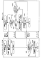
図1は、本発明の一実施例としてのデバイス管理システムの概要構成を示す説明図である。図1に示すデバイス管理システム1000は、ユーザ拠点に設置されたプリンタPRT1と、デバイス管理サービス提供者の監視拠点に設置された監視サーバSVと、を備えている。
A. Example:
A1. System overview:
FIG. 1 is an explanatory diagram showing a schematic configuration of a device management system as an embodiment of the present invention. A
ユーザ拠点において、プリンタPRT1は、ローカルエリアネットワークLAN1に接続されている。 At the user site, the printer PRT1 is connected to the local area network LAN1.
プリンタPRT1は、カスタムネットワークボードCNBを備えており、このカスタムネットワークボードCNBを介してローカルエリアネットワークLAN1に接続されている。そして、このローカルエリアネットワークLAN1は、ファイアウォールFWを介してインターネットINTに接続されている。 The printer PRT1 includes a custom network board CNB, and is connected to the local area network LAN1 via the custom network board CNB. The local area network LAN1 is connected to the Internet INT via a firewall FW.
一方、監視拠点において、監視サーバSVは、ローカルエリアネットワークLAN2に接続されており、このローカルエリアネットワークLAN2は、インターネットINTに接続されている。 On the other hand, at the monitoring base, the monitoring server SV is connected to the local area network LAN2, and the local area network LAN2 is connected to the Internet INT.
このデバイス管理システム1000は、プリンタPRT1における使用状況や故障発生などの所定の監視項目に対応する監視情報を、プリンタPRT1から監視サーバSVに送信し、監視サーバSVにおいてこれら情報を蓄積して監視するシステムである。
The
ここで、前述のファイアウォールFWでは、ローカルエリアネットワークLAN1に接続されたプリンタPRT1が、インターネットINT経由で外部から不正にアクセスされるのを避けるため、インターネットINT経由で受信するプリンタPRT1への接続要求を破棄するように設定されている。そこで、このデバイス管理システム1000では、プリンタPRT1が接続要求を監視サーバSVに送信し、プリンタPRT1と、監視サーバSVと、の間の接続を確立した上で、前述の監視情報を監視サーバSVに送信するようにしている。
Here, in the firewall FW described above, in order to prevent the printer PRT1 connected to the local area network LAN1 from being illegally accessed from the outside via the Internet INT, a connection request to the printer PRT1 received via the Internet INT is issued. It is set to be discarded. Therefore, in the
かかるデバイス管理システム1000を用いて、デバイス管理サービス提供者は、プリンタPRT1の保守サービスを提供することができる。例えば、監視サーバSVにおいて、プリンタPRT1で発生した故障についての監視情報を受信した場合に、この監視情報に基づき、故障修理や代替機と交換するといったサービスを提供することができる。
Using the
また、デバイス管理サービス提供者は、デバイス管理システム1000を用いて、プリンタPRT1の使用状況(例えば、印刷完了部数やトナー使用量)に応じて課金する課金サービスを提供することができる。
In addition, the device management service provider can use the
ここで、前述の監視情報は、プリンタPRT1において、カスタムネットワークボードCNBによって、監視設定ファイルに従って取得されて監視サーバSVに送信される。この監視設定ファイルは、所定の監視項目に対応する監視情報の格納場所を記載したファイルであり、プリンタの機種や提供するサービス種別(保守サービス/課金サービス)により異なる。 Here, the aforementioned monitoring information is acquired by the custom network board CNB in the printer PRT1 according to the monitoring setting file and transmitted to the monitoring server SV. This monitoring setting file is a file describing the storage location of monitoring information corresponding to a predetermined monitoring item, and differs depending on the printer model and the service type (maintenance service / billing service) provided.
そして、デバイス管理システム1000では、本発明の特徴部分として、プリンタPRT1の機種や、提供するサービス種別が変更された場合に、監視サーバSVにおいて、これら変更に応じた監視設定ファイルを生成し、カスタムネットワークボードCNBに配信する。
In the
図2は、図1に示すプリンタPRT1の概要構成を示す説明図である。 FIG. 2 is an explanatory diagram showing a schematic configuration of the printer PRT1 shown in FIG.
プリンタPRT1は、モノクロ印刷のみ可能なプリンタであり、プリンタ本体50と、プリンタ本体50に着脱自在に装着されたカスタムネットワークボードCNBと、を備えている。プリンタ本体50は、主としてプリンタエンジン20と、プリンタコントローラ30と、を備えており、それぞれ、内部バスによって接続されている。
The printer PRT1 is a printer capable of monochrome printing only, and includes a printer
なお、プリンタPRT1の機種名は「LP−9200B」であるが、これは、プリンタ本体50の種類(機種)を示している。
The model name of the printer PRT1 is “LP-9200B”, which indicates the type (model) of the printer
プリンタエンジン20は、図示せざるトナーカートリッジや感光体ドラムなど、用紙に印刷するためのハードウェア群から成る。プリンタコントローラ30は、図示せざるCPUやメモリ等を有するコンピュータであり、ローカルエリアネットワークLAN1を介して受信した印刷ジョブデータに従って、プリンタエンジン20を制御して印刷を実行させる。
The
また、プリンタコントローラ30は、プリンタエンジン20におけるトナー種別等、プリンタ本体50に関する種々の情報を収集して、MIB(Management Information Base)と呼ばれる形式で保存する。プリンタコントローラ30の有するメモリ(図示省略)は、このMIBの保存先としてMIB格納部31を備えている。
The
前述のMIBでは、プリンタ本体に関して予め規格で統一的に規定されている項目や、製造者によって独自に定義されている項目が定義されている。そして、これらの項目は、製造者や、機種や、項目の種類などに基づき、ツリー構造で管理されており、それぞれ、製造者や、機種や、項目の種類を示すオブジェクトID(OID)と呼ばれる識別番号が割り当てられている。 In the above-described MIB, items that are preliminarily defined in the standard for the printer body and items that are uniquely defined by the manufacturer are defined. These items are managed in a tree structure based on the manufacturer, model, item type, and the like, and are called object ID (OID) indicating the manufacturer, model, and item type, respectively. An identification number is assigned.
また、プリンタコントローラ30の有するメモリは、前述のMIB格納部31の他に、プリンタ本体50の機種名を保存するための機種名格納部32を備えている。この機種名格納部32には、出荷前に予めプリンタ本体50の機種名「LP−9200B」が保存されている。
In addition to the
一方、カスタムネットワークボードCNBは、主として、CPU10と、メモリ11と、ネットワークインタフェース部12と、内部バスインタフェース部13と、を備えており、それぞれ内部バスで接続されている。
On the other hand, the custom network board CNB mainly includes a
ネットワークインタフェース部12は、カスタムネットワークボードCNBに対してローカルエリアネットワークLAN1を接続するためのインタフェースから成る。また、内部バスインタフェース部13は、プリンタ本体50の内部バスと、カスタムネットワークボードCNBの内部バスと、を接続するためのインタフェースから成る。
The
メモリ11は、初期設定情報格納部11aと、監視設定ファイル格納部11bと、を備えている。これらのうち、初期設定情報格納部11aは、初期設定情報DSIを格納する領域である。
The
初期設定情報DSIは、カスタムネットワークボードCNBにおいて監視情報を取得して監視サーバSVに送信するために必要な情報であって、プリンタの機種や提供するサービス種別に依存しない情報である。具体的には、ネットワーク設定(プリンタPRT1に割り当てられたIPアドレスやサブネットマスクなど)や、監視情報を収集するタイミング(例えば、午前0時など)や、後述する設置IDなどを示す情報である。 The initial setting information DSI is information that is necessary for acquiring monitoring information in the custom network board CNB and transmitting it to the monitoring server SV, and is information that does not depend on the printer model or the type of service provided. Specifically, it is information indicating network settings (such as an IP address and subnet mask assigned to the printer PRT1), timing for collecting monitoring information (for example, midnight), installation ID described later, and the like.
一方、監視設定ファイル格納部11bは、プリンタの機種や提供するサービス種別に依存する、前述の監視設定ファイルMSFを保存する領域である。
On the other hand, the monitoring setting
なお、初期設定情報DSI及び初期状態における監視設定ファイルMSFは、プリンタPRT1の設置時に、初期設定情報格納部11a及び監視設定ファイル格納部11bに、それぞれ保存される。具体的には、プリンタPRT1の設置時に、設置作業員が、プリンタPRT1に設定用パソコンを接続して各種情報を設定することにより、初期設定情報DSI及び監視設定ファイルMSFが保存される。
The initial setting information DSI and the monitoring setting file MSF in the initial state are stored in the initial setting
また、メモリ11には、監視処理用プログラムが記憶されており、CPU10は、このプログラムをメモリ11から読み出して実行することにより、監視情報送信部10a及びポーリング部10bとして機能することになる。
The
図3は、図1に示す監視サーバSVの概要構成を示す説明図である。 FIG. 3 is an explanatory diagram showing a schematic configuration of the monitoring server SV shown in FIG.
監視サーバSVは、コンピュータ100で構成されており、主として、CPU110と、ハードディスク120と、メモリ130と、入出力インタフェース部140と、を備えており、それぞれ内部バスによって接続されている。また、監視サーバSVは、データを入力する装置としてキーボード150及びマウス151と、画像を出力する装置としてディスプレイ152と、を備えている。
The monitoring server SV is composed of a
入出力インタフェース部140は、コンピュータ100に対して、前述のキーボード150,マウス151,ディスプレイ152,ローカルエリアネットワークLAN2を接続するためのインタフェース群から成る。
The input /
コンピュータ100では、所定のオペレーティングシステムの下、アプリケーションプログラムが実行される。なお、このオペレーティングシステムには、各種ドライバが組み込まれ、前述のキーボード150,マウス151,ディスプレイ152が制御される。
In the
そして、前述のアプリケーションプログラムが起動され、メモリ130にロードされると、CPU110は、このアプリケーションプログラムを実行することにより、設定ファイル生成部110a,マスタ管理部110b,監視制御部110cとして機能することになる。
When the application program described above is activated and loaded into the
メモリ130は、送信データ格納部130aを備えている。また、ハードディスク120は、マスタデータベース120aと、機種情報データベース120bと、監視項目テーブル120cと、を備えている。
The
図4は、監視サーバSVのハードディスク120が備えるマスタデータベース120aを模式的に示す説明図である。
FIG. 4 is an explanatory diagram schematically showing the
図4に示すように、マスタデータベース120aは、各設置IDに対して、サービス種別と、機種名と、更新日時と、が対応付けられた各レコードから成る。
As shown in FIG. 4, the
設置IDとは、保守または課金サービス契約の識別情報であり、カスタムネットワークボードに予め設定される。この設置IDは、サービス契約の識別情報であるため、カスタムネットワークボードが交換されても設置IDは同一である。かかる設置IDの設定は、保守又は課金サービスの契約が新規になされた後、サービス対象の各プリンタが備えるカスタムネットワークボードに設定される。 The installation ID is identification information for a maintenance or billing service contract, and is set in advance in the custom network board. Since this installation ID is identification information of the service contract, the installation ID is the same even if the custom network board is replaced. The setting of the installation ID is set in a custom network board included in each printer to be serviced after a maintenance or billing service contract is newly made.
そして、各カスタムネットワークボードに設置IDが設定されると、監視拠点の作業員は、監視サーバSVが備えるキーボード150及びマウス151を用いて、設置IDと、契約されたサービス種別と、サービス対象のプリンタの機種名と、を入力し、マスタデータベース120aにレコードを追加する。このとき、レコードが追加された日時が、設置IDに対応付けて自動的に追記される。
When the installation ID is set for each custom network board, the worker at the monitoring base uses the
具体的には、例えば、図1に示すプリンタPRT1を対象として保守サービスの契約がなされ、プリンタPRT1が備えるカスタムネットワークボードCNBに対して、設置ID「A001」が割り当てられると、マスタデータベース120aには、図4の最上段に示すように、設置ID「A001」,サービス種別「保守」,機種名「LP−9200B」のレコードが追加され、その更新日時「2005/08/19,19:20」が追記される。
Specifically, for example, when a maintenance service contract is made for the printer PRT1 shown in FIG. 1 and the installation ID “A001” is assigned to the custom network board CNB included in the printer PRT1, the
なお、上述したように、設置IDは、カスタムネットワークボードの機器本体を示す識別情報ではなく、サービスを提供するのに用いられる識別情報である。具体的には、例えば、前述の「A001」は、カスタムネットワークボードCNBの機器本体の識別情報ではなく、「ユーザ拠点の1台のプリンタを対象とした、保守サービス」を示す識別情報である。 As described above, the installation ID is not identification information indicating the device main body of the custom network board but identification information used for providing a service. Specifically, for example, “A001” described above is not identification information of the device main body of the custom network board CNB but identification information indicating “maintenance service for one printer at a user base”.
従って、仮に、カスタムネットワークボードCNBが、故障等により他のカスタムネットワークボードと交換された場合、この交換されたカスタムネットワークボードに対して同じ設置ID「A001」を割り当てることにより、プリンタPRT1を対象プリンタとして、引き続き保守サービスが提供されることとなる。 Accordingly, if the custom network board CNB is replaced with another custom network board due to a failure or the like, the same installation ID “A001” is assigned to the replaced custom network board, so that the printer PRT1 is assigned to the target printer. As a result, maintenance services will continue to be provided.
また、仮に、プリンタPRT1のプリンタ本体50が、故障等により他のプリンタ本体と交換された場合、この交換された他のプリンタ本体に、カスタムネットワークボードCNBを付け替えることにより、この交換後のプリンタ本体を備えるプリンタを対象プリンタとして、引き続き保守サービスが提供されることとなる。
If the printer
図5は、監視サーバSVのハードディスク120が備える監視項目テーブル120cを模式的に示す説明図である。
FIG. 5 is an explanatory diagram schematically showing a monitoring item table 120c included in the
図5に示すように、監視項目テーブル120cでは、サービス種別(課金/保守)に対して、それぞれ、各サービスを提供する上で必要な監視項目が対応付けられている。 As shown in FIG. 5, in the monitoring item table 120c, monitoring items necessary for providing each service are associated with the service type (billing / maintenance).
具体的には、保守サービスに対しては、構成情報としてトレイ種別,ファームウェアVer.が、消耗品情報としてトナー種別,感光体種別,トナー残量が、アラート情報としてアラートが、それぞれ監視項目として対応付けられている。一方、課金サービスに対しては、保守サービスに対応付けられた各監視項目と重複した構成情報,消耗品情報,アラートの各項目の他に、印刷ジョブ情報として処理済みジョブID及び印刷完了部数が対応付けられている。 Specifically, for the maintenance service, the tray type, firmware Ver. However, the toner type, the photosensitive member type, and the toner remaining amount are associated with the consumable information, and the alert is associated with the alert information. On the other hand, for the billing service, in addition to the configuration information, consumable information, and alert items that overlap with the monitoring items associated with the maintenance service, the processed job ID and the number of print completions are included as print job information. It is associated.
図6は、監視サーバSVのハードディスク120が備える機種情報データベース120bを模式的に示す説明図である。
FIG. 6 is an explanatory diagram schematically showing a
図6に示すように、機種情報データベース120bは、プリンタ本体の機種名に対して、印刷モード(モノクロ/カラー)や、適用用紙サイズといった情報の他に、監視項目のOIDが対応付けられた各レコードから成る。なお、OIDは、例えば、「1.4.2.2.1.3」のように、ピリオドで区切られた数字で表されるが、説明の便宜上、OID110やOID280のように示す。
As shown in FIG. 6, the
ここで、プリンタの機種名に対応付けられているOIDの示す監視項目は、監視項目テーブル120cにおいて、保守サービスに対応付けられた監視項目と、課金サービスに対応付けられた監視項目と、を合わせた項目を示す。なお、保守サービスに対応付けられた監視項目は、課金サービスに対応付けられた監視項目に全て含まれるので、結果的に課金サービスに対応付けられた各監視項目が挙げられている。 Here, the monitoring item indicated by the OID associated with the printer model name is obtained by combining the monitoring item associated with the maintenance service and the monitoring item associated with the charging service in the monitoring item table 120c. Indicates an item. The monitoring items associated with the maintenance service are all included in the monitoring items associated with the charging service, and as a result, the monitoring items associated with the charging service are listed.
上述したように、OIDは、製造者や、機種や、項目の種類を示すので、機種が異なると、同じ監視項目でも異なるOIDが割り当てられることとなる。具体的には、例えば、図6に示すように、監視項目「トレイ種別」について、機種名「LP−9200B」では「OID110」が割り当てられているのに対し、機種名「LP−9000C」では「OID210」が割り当てられている。 As described above, the OID indicates the manufacturer, model, and item type. Therefore, if the model is different, different OIDs are assigned to the same monitoring item. Specifically, for example, as shown in FIG. 6, for the monitoring item “tray type”, “OID110” is assigned in the model name “LP-9200B”, whereas in the model name “LP-9000C”. “OID210” is assigned.
そして、前述の監視設定ファイルMSFでは、このOIDが、監視項目に対応する監視情報の格納場所として記載される。 In the above-described monitoring setting file MSF, this OID is described as the storage location of the monitoring information corresponding to the monitoring item.
図7は、機種名「LP−9000C」のプリンタを対象として、保守サービスを提供する場合に用いられる監視設定ファイルMSFの内容を示す説明図である。 FIG. 7 is an explanatory diagram showing the contents of the monitoring setting file MSF used when providing a maintenance service for the printer with the model name “LP-9000C”.
例えば、機種名「LP−9000C」のプリンタを対象として、保守サービスを提供する場合に用いられる監視設定ファイルMSFについて考える。図5に示したように、保守サービスに対しては、トレイ種別,ファームウェアVer.,トナー種別,感光体種別,トナー残量,アラートが対応付けられている。そして、図6に示すように、これらの監視項目のLP−9000CにおけるOIDは、それぞれ、OID210,OID220,OID235,OID242,OID250,OID260である。 For example, consider a monitoring setting file MSF used when a maintenance service is provided for a printer of model name “LP-9000C”. As shown in FIG. 5, for the maintenance service, the tray type, firmware Ver. , Toner type, photoconductor type, toner remaining amount, and alert are associated with each other. As shown in FIG. 6, the OIDs of these monitoring items in LP-9000C are OID210, OID220, OID235, OID242, OID250, and OID260, respectively.
従って、この場合、図7に示すように、監視設定ファイルMSFには、これらOIDが記載されることとなる。なお、監視設定ファイルMSFは、監視項目のOIDの他、ファイルの属性として、監視設定ファイルMSFの生成日時が記録されている。 Therefore, in this case, as shown in FIG. 7, these OIDs are described in the monitoring setting file MSF. The monitoring setting file MSF records the generation date and time of the monitoring setting file MSF as the file attribute in addition to the OID of the monitoring item.
なお、上述した監視サーバSVが請求項における設定ファイル生成装置に相当し、上述したカスタムネットワークボードCNBが請求項におけるデバイス監視装置に相当し、上述したマスタデータベース120a及び監視項目テーブル120cが請求項における第1のテーブルに相当し、上述した機種情報データベース120bが請求項における第2のテーブルに相当し、上述した設置IDが請求項におけるサービス契約識別情報に相当する。
The monitoring server SV described above corresponds to the setting file generation device in the claims, the custom network board CNB described above corresponds to the device monitoring device in the claims, and the
監視サーバSV(図3)内の設定ファイル生成部110aは請求項における設定ファイル生成装置の設定ファイル生成手段として機能する。監視制御部110cは保持情報受信手段、格納場所決定手段、時期判断手段、判断結果受信手段、及び、設定ファイル送信手段として機能する。ハードディスク120及びメモリ130は、請求項における設定ファイル生成装置の各種の記憶手段として機能する。カスタムネットワークボードCNB(図2)内の監視情報送信部10aは、請求項におけるデバイス監視装置の保持情報送信手段として機能する。
The setting file generator 110a in the monitoring server SV (FIG. 3) functions as a setting file generator of the setting file generator in the claims. The
A2.監視処理概要:
デバイス管理システム1000における監視処理の概要について、簡単に説明する。
A2. Overview of monitoring process:
An overview of the monitoring process in the
図2に示すプリンタPRT1において、監視情報送信部10aは、初期設定情報格納部11aに保存されている初期設定情報DSIに含まれる監視タイミングで、監視設定ファイル格納部11bに保存されている監視設定ファイルMSFを読み出す。そして、監視情報送信部10aは、監視設定ファイルMSFに記載された監視項目に対応する監視情報を、プリンタコントローラ30の備えるMIB格納部31に格納されたMIBから取得する。
In the printer PRT1 shown in FIG. 2, the monitoring
そして、監視情報送信部10aは、初期設定情報DSIに含まれるネットワーク設定に従って監視サーバSVとの間の接続を確立した上で、取得した監視情報を、ローカルエリアネットワークLAN1及びインターネットINTを介して、監視サーバSVに送信する。
The monitoring
一方、図3に示す監視サーバSVにおいて、監視制御部110cは、プリンタPRT1から送信された監視情報を受信してハードディスク120に格納する。このようにして、監視サーバSVのハードディスク120にプリンタPRT1についての監視情報が蓄積されると、この蓄積された監視情報に基づき、保守または課金が行われる。
On the other hand, in the monitoring server SV shown in FIG. 3, the
ここで、プリンタPRT1は、上述した監視情報の送信の他に、監視処理の一部として、監視サーバSVに対して定期的にポーリングを行っている。このポーリングは、リセット等のコマンドや、生成した監視設定ファイルMSFなどのデータを、監視サーバSVからプリンタPRT1に送信することを目的としている。 Here, in addition to the transmission of the monitoring information described above, the printer PRT1 periodically polls the monitoring server SV as part of the monitoring process. The purpose of this polling is to transmit a command such as reset and data such as the generated monitoring setting file MSF from the monitoring server SV to the printer PRT1.
このような構成としているのは、上述したように、監視サーバSVとプリンタPRT1との間の接続を、監視サーバSV側から確立することができないので、監視サーバSVが、リセット等のコマンドや監視設定ファイルMSFなどのデータを、プリンタPRT1に対して自発的に送信することができないためである。 As described above, since the connection between the monitoring server SV and the printer PRT1 cannot be established from the monitoring server SV side as described above, the monitoring server SV can execute commands such as reset and monitoring. This is because data such as the setting file MSF cannot be spontaneously transmitted to the printer PRT1.
具体的には、図2に示すプリンタPRT1において、ポーリング部10bは、初期設定情報DSIに含まれる所定の時間間隔で監視サーバSVとの間の接続を確立する。一方、図3に示す監視サーバSVにおいて、プリンタPRT1に送信しようとするデータは、メモリ130が備える送信データ格納部130aに保存される。そして、ポーリングによって監視サーバSVと、プリンタPRT1と、の間の接続が確立されると、監視制御部110cは、送信データ格納部130aからデータを読み出して、ローカルエリアネットワークLAN2及びインターネットINTを介してプリンタPRT1に送信する。
Specifically, in the printer PRT1 shown in FIG. 2, the
A3.プリンタ本体交換時における監視設定ファイル生成処理:
本発明の特徴部分である監視設定ファイル生成処理について、まず、プリンタ本体を交換した場合について説明する。
A3. Monitoring setting file generation processing when the printer is replaced:
The monitoring setting file generation process, which is a feature of the present invention, will be described first when the printer main body is replaced.
監視設定ファイル生成処理の前提として、ユーザとデバイス管理サービス提供者との間で、図1に示すプリンタPRT1を対象として保守サービスの契約がなされ、カスタムネットワークボードCNBの設置IDとして、「A001」が割り当てられている。そして、監視サーバSVでは、図4に示すように、マスタデータベース120aに、設置IDが「A001」のレコードが追加されている。そして、監視サーバSVは、上述した監視処理により、プリンタPRT1から送信される監視情報を蓄積している。
As a premise of the monitoring setting file generation process, a maintenance service contract is made for the printer PRT1 shown in FIG. 1 between the user and the device management service provider, and “A001” is set as the installation ID of the custom network board CNB. Assigned. In the monitoring server SV, as shown in FIG. 4, a record with the installation ID “A001” is added to the
一方、プリンタPRT1では、割り当てられた設置ID「A001」が、初期設定情報DSIの一部として初期設定情報格納部11a格納されており、また、保守サービスの監視項目について、プリンタ本体50の機種名に対応付けられたOIDが、監視設定ファイルMSFに記載されて、監視設定ファイル格納部11bに格納されている。
On the other hand, in the printer PRT1, the assigned installation ID “A001” is stored as an initial setting
以上の前提の下、プリンタPRT1のプリンタ本体50が、図1において破線で示すプリンタ本体60(機種名=LP−9000C)に交換された場合について考える。なお、このプリンタ本体60はカラー印刷も可能な機種であり、その構成は、図2に示すプリンタPRT1のプリンタ本体50の構成と比較して、プリンタエンジンはカラー印刷用であるため異なるが、プリンタコントローラは同じ構成である。そして、プリンタ本体60の機種名格納部には、機種名「LP−9000C」が予め格納されている。
Consider the case where the printer
この場合、ユーザ拠点において、保守作業員によってプリンタPRT1のプリンタ本体50からカスタムネットワークボードCNBがはずされ、プリンタ本体60に装着されてローカルエリアネットワークLAN1に接続される。なお、このプリンタ本体60にカスタムネットワークボードCNBが装着されたプリンタを、以下、「プリンタPRT3」と呼ぶ。
In this case, the custom network board CNB is removed from the printer
カスタムネットワークボードCNBのメモリ11には、カスタムネットワークボードCNBがプリンタ本体50に装着されていた際に保存されていた、初期設定情報DSI及び監視設定ファイルMSFが保存されたままとなっている。すなわち、設置IDとして「A001」が保存されており、また、監視設定ファイルMSFには、プリンタ本体50の機種名「LP−9200B」に対応する、保守サービスに必要な監視項目のOIDが記載されている。
In the
それ故、このままでは、監視情報送信部10aは、機種名「LP−9200B」に対応するOIDに基づき、プリンタ本体60のMIBから監視情報を取得することとなる。その結果、機種名「LP−9000C」のプリンタPRT3に対応する、保守サービスに必要な監視項目に対応する監視情報を取得することができない。
Therefore, as it is, the monitoring
一方、監視拠点において、監視サーバSVでは、プリンタ本体50がプリンタ本体60に交換された後において、マスタデータベース120aは更新されていない。すなわち、設置ID「A001」のレコードについては、図4の最上段に示すままであり、機種名については、「LP−9200B」のままである。
On the other hand, at the monitoring base, after the printer
そして、ユーザ拠点において、保守作業員によりプリンタPRT3の電源がオンされると、プリンタ本体60に装着されたカスタムネットワークボードCNBにおいて、本発明の特徴部分である監視設定ファイル生成処理が開始する。
When the power of the printer PRT3 is turned on by a maintenance worker at the user site, the monitoring setting file generation process, which is a feature of the present invention, is started in the custom network board CNB mounted on the printer
なお、監視サーバSVは既に電源がオンされており、監視サーバSVにおいては、既に監視設定ファイル生成処理が開始されている。また、プリンタPRT3の電源がオンされると、ポーリング部10bは、監視設定ファイル生成処理とは別に、上述した定期的なポーリングを開始する。
Note that the monitoring server SV is already powered on, and the monitoring server SV has already started the monitoring setting file generation process. When the printer PRT3 is turned on, the
図8は、本実施例における監視設定ファイル生成処理の手順を示すフローチャートである。図8において、左側はカスタムネットワークボードCNBにおける手順を、右側は監視サーバSVにおける手順を、それぞれ示す。 FIG. 8 is a flowchart showing the procedure of the monitoring setting file generation process in the present embodiment. In FIG. 8, the left side shows the procedure in the custom network board CNB, and the right side shows the procedure in the monitoring server SV.
図8に示す監視設定ファイル生成処理が開始されると、図2に示すカスタムネットワークボードCNBにおいて、監視情報送信部10aは、初期設定情報格納部11aから設置IDを、プリンタ本体60の機種名格納部から機種名を、それぞれ読み出す。また、監視情報送信部10aは、監視設定ファイル格納部11bに格納されている監視設定ファイルMSFを読み出し、監視設定ファイルMSFの属性である生成日時を取得する。
When the monitoring setting file generation process shown in FIG. 8 is started, in the custom network board CNB shown in FIG. 2, the monitoring
そして、監視情報送信部10aは、初期設定情報DSIに含まれるネットワーク設定に従って監視サーバSVとの間の接続を確立した上で、読み出した設置ID,機種名及び取得した生成日時を、監視サーバSVに送信する(ステップS202)。次に、監視情報送信部10aは、図示せざるタイマを起動する(ステップS204)
Then, the monitoring
前述のように、初期設定情報格納部11aに設置IDとして「A001」が保存され、機種名格納部に「LP−9000C」が保存されている場合、これら「A001」及び「LP−9000C」と、監視設定ファイルMSFの生成日時と、が監視サーバSVに送信される。
As described above, when “A001” is stored as the installation ID in the initial setting
一方、図3に示す監視サーバSVでは、監視設定ファイル生成処理が開始されると、監視制御部110cは、プリンタPRT1から設置ID,機種名,生成日時を受信したか否かを判定している(ステップS302)。そして、監視制御部110cは、受信したと判定した場合に、受信した機種名が、マスタデータベース120aにおける、受信した設置IDのレコードに記載されている機種名と一致するか否かを判定する(ステップS304)。
On the other hand, in the monitoring server SV shown in FIG. 3, when the monitoring setting file generation process is started, the
前述のように、設置ID「A001」,機種名「LP−9000C」,生成日時を受信すると、監視制御部110cは、この機種名「LP−9000C」が、図4に示すマスタデータベース120aにおいて、設置ID「A001」のレコードの機種名「LP−9200B」と一致しないと判定することとなる。
As described above, when the installation ID “A001”, the model name “LP-9000C”, and the generation date / time are received, the
このように、監視制御部110cが、一致しないと判定した場合、マスタ管理部110bは、受信した機種名に基づき、マスタデータベース120aの該当するレコードを更新する(ステップS306)。
As described above, when the
具体的には、前述のように、受信した機種名が「LP−9000C」である場合、マスタ管理部110bは、マスタデータベース120aの設置ID「A001」のレコードについて、機種名を「LP−9200B」から「LP−9000C」に変更して更新する。なお、この場合、設置ID「A001」のレコードの更新日時も更新されることとなる。
Specifically, as described above, when the received model name is “LP-9000C”, the
次に、設定ファイル生成部110aは、更新されたマスタデータベース120aのレコードと、監視項目テーブル120cと、機種情報データベース120bと、に基づき、監視設定ファイルMSFを生成して、送信データ格納部130aに格納する(ステップS310)。
Next, the setting file generation unit 110a generates a monitoring setting file MSF based on the updated record of the
具体的には、前述のように設置ID「A001」のレコードが更新されると、設定ファイル生成部110aは、設置ID「A001」のサービス種別が「保守」であることから、図5に示す監視項目テーブル120cを参照して、保守サービスにおいて取得すべき監視項目を決定する。そして、設定ファイル生成部110aは、図6に示す機種情報データベース120bを参照して、決定した監視項目に対応する、機種名「LP−9000C」におけるOIDを決定する。そして、設定ファイル生成部110aは、この決定したOIDを記載した監視設定ファイルMSFを生成して、送信データ格納部130aに格納する。
Specifically, when the record of the installation ID “A001” is updated as described above, the setting file generation unit 110a indicates that the service type of the installation ID “A001” is “maintenance”, and therefore, as illustrated in FIG. Referring to the monitoring item table 120c, the monitoring item to be acquired in the maintenance service is determined. Then, the setting file generation unit 110a refers to the
なお、このようにして生成された監視設定ファイルMSFの内容は、図7に示す内容と同じものとなる。 Note that the contents of the monitoring setting file MSF generated in this way are the same as the contents shown in FIG.
ここで、上述したように、プリンタPRT3においてポーリング部10bは、定期的なポーリングを行っており、前述のように、送信データ格納部130aに監視設定ファイルMSFが格納された後において、プリンタPRT3と監視サーバSVとの間の接続が確立されると、監視サーバSVにおいて監視制御部110cは、監視設定ファイルMSFをプリンタPRT3に送信することとなる。
Here, as described above, in the printer PRT3, the
一方、プリンタPRT3において、監視情報送信部10aは、上述したステップS204の処理においてタイマを起動した後、タイマ満了までの所定期間内に、監視サーバSVから監視設定ファイルMSFを受信したか否かを判定している(ステップS206)。
On the other hand, in the printer PRT3, the monitoring
そして、前述のように、定期的なポーリングの結果、所定期間内に監視サーバSVから監視設定ファイルMSFを受信した場合、監視情報送信部10aは、受信した監視設定ファイルMSFを監視設定ファイル格納部11bに格納し、既に存在する監視設定ファイルMSFに上書きする(ステップS208)。
As described above, when the monitoring setting file MSF is received from the monitoring server SV within a predetermined period as a result of the periodic polling, the monitoring
以上の監視設定ファイル生成処理の結果、図7に示す内容の監視設定ファイルMSFが監視設定ファイル格納部11bに保存されることとなるので、監視情報送信部10aは、プリンタ本体60のMIBから、保守サービスに必要な所定の監視項目に対応する監視情報を取得することができる。
As a result of the above monitoring setting file generation process, the monitoring setting file MSF having the contents shown in FIG. 7 is stored in the monitoring setting
A4.契約内容変更時における監視設定ファイル生成処理:
続いて、契約内容を変更した場合における監視設定ファイル生成処理を説明する。
A4. Monitoring setting file generation processing when changing contract contents:
Next, the monitoring setting file generation process when the contract content is changed will be described.
なお、この場合の前提は、上述したプリンタ本体交換時における監視設定ファイル生成処理の前提と同じであるので説明を省略する。ただし、プリンタPRT1に格納されている監視設定ファイルMSFの生成日時は、「2005/8/20,9:20」であるものとする。 Note that the premise in this case is the same as the premise of the monitor setting file generation process at the time of replacing the printer main body described above, and thus the description thereof is omitted. However, it is assumed that the generation date and time of the monitoring setting file MSF stored in the printer PRT1 is “2005/8/20, 9:20”.
かかる前提の下、プリンタPRT1を対象として、保守サービスの他に、課金サービスも提供するように契約内容が変更された場合について考える。 Under such a premise, a case is considered where the contents of the contract are changed so as to provide a charging service in addition to the maintenance service for the printer PRT1.
この場合、監視拠点において、監視サーバSVでは、作業員によって、マスタデータベース120aのうち、設置ID「A001」のレコードについて、サービス種別が、「保守」から「保守,課金」に書き換えられて更新される。
In this case, at the monitoring base, in the monitoring server SV, the operator rewrites the service type of the record with the installation ID “A001” in the
なお、この設置ID「A001」のレコードの更新日時は、この更新の日時で上書きされることとなる。ここでは、「2005/8/19,19:20」から、「2005/11/5,14:00」に上書きされたものとする。 The update date / time of the record with the installation ID “A001” is overwritten with the update date / time. Here, it is assumed that “2005/8/19, 19:20” is overwritten to “2005/11/5, 14:00”.
一方、プリンタPRT1では、監視設定ファイル格納部11bに保存されている監視設定ファイルMSFに、保守サービスに対応する監視項目のOIDが記載されたままとなっている。すなわち、図5の監視項目テーブル120cに示すように、構成情報,消耗品情報,アラート情報についてのOIDが記載されている。
On the other hand, in the printer PRT1, the monitoring item OID corresponding to the maintenance service is still described in the monitoring setting file MSF stored in the monitoring setting
しかしながら、課金サービスに対しては、図5に示すように、これらの項目の他に、印刷ジョブ情報も必要な情報として対応付けられている。それ故、このままでは、印刷ジョブ情報をプリンタ本体50のMIBから取得できず、プリンタPRT1を対象プリンタとして課金サービスを提供することができない。
However, for the billing service, as shown in FIG. 5, in addition to these items, print job information is also associated as necessary information. Therefore, as it is, the print job information cannot be acquired from the MIB of the printer
なお、監視サーバSVは既に電源がオンされており、監視サーバSVにおいては、既に監視設定ファイル生成処理が開始されている。また、ユーザ拠点において、プリンタPRT1は、毎日定時に電源のオフ/オンがされる。 Note that the monitoring server SV is already powered on, and the monitoring server SV has already started the monitoring setting file generation process. Further, at the user site, the printer PRT1 is turned off / on at a fixed time every day.
そして、契約内容の変更の後に定時となり、プリンタPRT1の電源がオンされると、カスタムネットワークボードCNBにおいて、上述した監視設定ファイル生成処理が開始する。なお、プリンタPRT1の電源がオンされると、ポーリング部10bは、監視設定ファイル生成処理とは別に、上述した定期的なポーリングを開始する。
When the power of the printer PRT1 is turned on after the contract contents are changed, the above-described monitoring setting file generation process starts in the custom network board CNB. When the printer PRT1 is powered on, the
以下、カスタムネットワークボードCNB及び監視サーバSVにおける手順は、図8のフローチャートに示す手順と同じであるので、上述したプリンタ本体交換時における監視設定ファイル生成処理で説明した手順については、簡単に説明する。 Hereinafter, since the procedure in the custom network board CNB and the monitoring server SV is the same as the procedure shown in the flowchart of FIG. 8, the procedure described in the monitoring setting file generation process at the time of replacing the printer main body will be briefly described. .
図8に示す監視設定ファイル生成処理が開始されると、図2に示すプリンタPRT1において、監視情報送信部10aは、設置ID「A001」,機種名「LP−9200B」,監視設定ファイルMSFの生成日時「2005/8/20,9:20」を監視サーバSVに送信し(ステップS202)、図示せざるタイマを起動する(ステップS204)。
When the monitoring setting file generation process shown in FIG. 8 is started, in the printer PRT1 shown in FIG. 2, the monitoring
一方、図3に示す監視サーバSVにおいて、監視制御部110cは、プリンタPRT1から設置ID,機種名,生成日時を受信したか否かを判定しており(ステップS302)、前述のように、設置ID,機種名,生成日時を受信すると、受信した機種名が、マスタデータベース120aにおいて受信した設置ID「A001」のレコードに記載されている機種名と一致するか否かを判定する(ステップS304)。
On the other hand, in the monitoring server SV shown in FIG. 3, the
図4に示すように、マスタデータベース120aにおいて、設置ID「A001」のレコードに記載されている機種名は「LP−9200B」であるので、上述したプリンタ本体交換時とは異なり、監視制御部110cは、一致すると判定することとなる。
As shown in FIG. 4, in the
そして、一致すると判定した場合、監視制御部110cは、受信した生成日時が、マスタデータベース120aにおける、受信した設置IDのレコードに記載されている更新日時よりも前であるか否かを判定する(ステップS308)。
When it is determined that they match, the
前述のように、設置ID「A001」のレコードの更新日時は、契約内容の変更の後に「2005/11/5,14:00」に上書きされている。従って、受信した生成日時「2005/8/20,9:20」は、この更新日時よりも前となるので、この場合、監視制御部110cは前であると判定することとなる。
As described above, the update date and time of the record with the installation ID “A001” is overwritten with “2005/11/5, 14:00” after the contract contents are changed. Accordingly, the received generation date “2005/8/20, 9:20” is earlier than this update date, and in this case, the
そして、監視制御部110cは、ステップS308の処理において、前であると判定した場合、上述したステップS310の処理を実行し、監視設定ファイルMSFを生成する。
If the
具体的には、設定ファイル生成部110aは、設置ID「A001」のサービス種別が、今度は、「保守,課金」であることから、図5に示す監視項目テーブル120cを参照して、保守サービス及び課金サービスで取得すべき監視項目を決定する。この場合、構成情報,消耗品情報,アラート情報の他に、印刷ジョブ情報についても監視項目として決定することとなる。次に、設定ファイル生成部110aは、図6に示す機種情報データベース120bを参照して、決定した監視項目に対応する、機種名「LP−9200B」におけるOIDを決定する。
Specifically, since the service type of the installation ID “A001” is “maintenance, billing” this time, the setting file generation unit 110a refers to the monitoring item table 120c shown in FIG. And monitoring items to be acquired by the billing service. In this case, in addition to the configuration information, consumable information, and alert information, print job information is also determined as a monitoring item. Next, the setting file generation unit 110a refers to the
そして、設定ファイル生成部110aは、この決定したOIDを記載した監視設定ファイルを生成して、送信データ格納部130aに格納する(ステップS310)。
Then, the setting file generation unit 110a generates a monitoring setting file in which the determined OID is described, and stores it in the transmission
以下、プリンタPRT1において、上述したステップS206〜ステップS208の処理が行われ、新たに生成された監視設定ファイルMSFが、監視設定ファイル格納部11bに格納されることとなる。
Thereafter, in the printer PRT1, the processes in steps S206 to S208 described above are performed, and the newly generated monitoring setting file MSF is stored in the monitoring setting
その結果、構成情報,消耗品情報,アラート情報の他、印刷ジョブ情報についてのOIDが記載された監視設定ファイルMSFが、監視設定ファイル格納部11bに保存されることとなる。従って、この監視設定ファイルMSFに基づき、監視情報送信部10aは、プリンタ本体50のMIBから印刷ジョブ情報を取得することができる。その結果、印刷ジョブ情報を含む課金サービスに必要な監視情報が、監視サーバSVに送信されることとなり、プリンタPRT1を対象プリンタとして保守及び課金サービスを提供することができる。
As a result, the monitoring setting file MSF in which the OID for the print job information in addition to the configuration information, the consumable information, and the alert information is stored in the monitoring setting
A5.実施例の効果:
以上説明したように、監視サーバSVでは、マスタデータベース120a及び監視項目テーブル120cにより、設置IDに対して、サービス種別に応じた監視項目が対応付けられていると共に、機種情報データベース120bにより、機種名に対して取得すべき監視項目のOIDが対応付けられている。そして、プリンタの電源がオンされると、カスタムネットワークボードCNBは、設置IDと共に、機種名を監視サーバSVに送信するようにしている。
A5. Effects of the embodiment:
As described above, in the monitoring server SV, the monitoring item according to the service type is associated with the installation ID by the
従って、プリンタ本体50が別の機種のプリンタ本体60に交換された場合に、監視サーバSVのマスタ管理部110bは、送信された設置IDのレコードに記載された機種名を、交換後のプリンタ本体の機種名に変更してレコードを更新することができる。そして、設定ファイル生成部110aは、この更新されたレコードに基づき、プリンタPRT3を対象プリンタとして保守サービスを提供するための監視設定ファイルMSFを、新たに生成することができる。
Therefore, when the printer
そして、このように生成された設定ファイルMSFがプリンタPRT3に送信され、監視設定ファイル格納部11bに格納されるので、監視情報送信部10aは、交換後のプリンタ本体60から適切な監視情報を取得して監視サーバSVに送信することができる。その結果、デバイス管理サービス提供者は、プリンタ本体の交換後においても、デバイス管理システム1000を用いて、保守サービスを継続して提供することができる。
Since the setting file MSF generated in this way is transmitted to the printer PRT3 and stored in the monitoring setting
また、監視サーバSVでは、各レコードの更新日時を記録するようにしている。そして、プリンタの電源がオンされると、カスタムネットワークボードCNBは、設置IDと共に、監視設定ファイル格納部11bに格納されている監視設定ファイルMSFの生成日時を、監視サーバSVに送信するようにしている。そして、監視サーバSVでは、受信した生成日時が更新日時よりも前である場合に、監視設定ファイルMSFを生成するようにしている。
The monitoring server SV records the update date and time of each record. When the printer is turned on, the custom network board CNB transmits the generation date and time of the monitoring setting file MSF stored in the monitoring setting
ここで契約内容が変更された場合には、監視設定ファイル格納部11bに格納されている監視設定ファイルMSFの生成日時は、マスタデータベース120aにおける該当するレコードの更新日時よりも前となる。従って、前述のような構成とすることで、監視サーバSVは、契約内容の変更に応じて、変更後の契約内容に従った新たな監視設定ファイルを生成することができる。そして、生成された新たな監視設定ファイルはカスタムネットワークボードCNBに送信されるので、監視情報送信部10aは、変更後の契約内容(サービス)に応じた監視項目について、プリンタ本体50のMIBから監視情報を取得することができる。
Here, when the contract contents are changed, the generation date / time of the monitoring setting file MSF stored in the monitoring setting
なお、仮に、マスタデータベース120aを更新したら、プリンタPRT1からの設置ID等の受信の有無に関わらず、必ず監視設定ファイルMSFを生成するような構成である場合、設置されていたプリンタPRT1が撤去され、監視設定ファイルMSFが送信されることがない場合でも、監視設定ファイルMSFが新たに生成されてしまう。
If the
一方、本実施例では、プリンタPRT1から設置ID等を受信した場合に、監視設定ファイルMSFを生成するようにしている。従って、プリンタPRT1が設置されており、通信が可能な場合にのみ、監視設定ファイルMSFが新たに生成されて監視設定ファイル格納部11bに格納されることとなる。その結果、設定ファイル生成部110aは余計な処理を実行しなくて済み、また、送信データ格納部130aの効率的な使用が可能となる。
On the other hand, in this embodiment, when the installation ID or the like is received from the printer PRT1, the monitoring setting file MSF is generated. Accordingly, only when the printer PRT1 is installed and communication is possible, the monitoring setting file MSF is newly generated and stored in the monitoring setting
B.変形例:
なお、本発明は、前述の実施例や実施形態に限られるものではなく、その要旨を逸脱しない範囲において、種々の態様において実施することが可能であり、例えば以下のような変形も可能である。
B. Variations:
The present invention is not limited to the above-described examples and embodiments, and can be implemented in various modes without departing from the gist thereof. For example, the following modifications are possible. .
B1.変形例1:
上述した実施例では、初期状態における監視設定ファイルMSFは、プリンタPRT1の設置時に設置作業員が各情報を設定することにより、監視設定ファイル格納部11bに格納される構成であったが、本発明は、これに限定されるものではない。例えば、上述した監視設定ファイル生成処理によって格納される構成であってもよい。
B1. Modification 1:
In the above-described embodiment, the monitoring setting file MSF in the initial state is stored in the monitoring setting
このような構成においては、設置作業員が、プリンタPRT1を設置した後、監視設定ファイルMSFを生成することなく、プリンタPRT1の電源をオンすることで、上述した監視設定ファイル生成処理を開始させるようにする。ただし、マスタデータベース120aにおいて、契約の後に新規追加するレコードに、機種名を記載しないようにする。
In such a configuration, after the installation worker installs the printer PRT1, the above-described monitoring setting file generation process is started by turning on the printer PRT1 without generating the monitoring setting file MSF. To. However, in the
そして、監視サーバSVにおいて監視制御部110cが、上述したステップS304の処理として、受信した機種名が、マスタデータベース120aにおいて受信した設置IDのレコードに記載されている機種名と一致するか否かを判定する際に、レコードに機種名が記載されていない場合には、一致しないものと判定するようにする。
Then, in the monitoring server SV, the
その結果、監視サーバSVにおいて監視制御部110cは、ステップS304の処理において、機種名が一致しないと判定することとなる。従って、上述したステップS306及びステップS310の処理が行われることとなり、プリンタPRT1の機種名及び契約されているサービスに対応する監視設定ファイルMSFが生成されて、プリンタPRT1に送信されることとなる。
As a result, in the monitoring server SV, the
このような構成とすることで、プリンタPRT1の設置時においても、設置作業員が監視項目や格納場所を設定用パソコンから入力して、監視設定ファイルMSFを生成する作業を省くことができる。 With such a configuration, even when the printer PRT1 is installed, it is possible to omit the work of the installation worker inputting the monitoring items and the storage location from the setting personal computer and generating the monitoring setting file MSF.
B2.変形例2:
上述した実施例では、契約内容が更新されてマスタデータベース120aが更新された後に、更新後のサービス種別等に対応した監視設定ファイルMSFが生成されるのは、監視設定ファイル生成処理のステップS308の処理において、受信した生成日時が、マスタデータベース120aにおける、受信した設置IDのレコードに記載されている更新日時よりも前であると判定された場合であるが、本発明は、これに限定されるものではない。
B2. Modification 2:
In the embodiment described above, after the contract contents are updated and the
例えば、カスタムネットワークボードCNBから生成日時等を受信する前であっても、マスタデータベース120aが更新された後すぐに、更新されたマスタデータベース120aのレコードと、監視項目テーブル120cと、機種情報データベース120bと、に基づき、監視設定ファイルMSFを生成するようにしてもよい。
For example, even before the generation date and time is received from the custom network board CNB, immediately after the
このような構成の場合、設定ファイル生成部110aは、生成した監視設定ファイルMSFを、送信データ格納部130a以外のメモリ130の領域に記憶させておくとよい。そして、監視サーバSVでは、カスタムネットワークボードCNBから設置ID,機種名,生成日時を受信した場合に、上述したステップS302〜ステップS308の処理を実行するようにする。そして、ステップS308の処理において、受信した生成日時が、マスタデータベース120aにおける、受信した設置IDのレコードに記載されている更新日時よりも前であると判定された場合に、設定ファイル生成部110aは、監視設定ファイルMSFを生成する処理(ステップS310)に代えて、新たに生成した監視設定ファイルMSFを送信データ格納部130aに格納するようにすればよい。
In such a configuration, the setting file generation unit 110a may store the generated monitoring setting file MSF in an area of the
このような構成であっても、その後の定期なポーリングの結果、新たに生成された監視設定ファイルMSFがプリンタPRT1に送信されることとなる。 Even with such a configuration, a newly generated monitoring setting file MSF is transmitted to the printer PRT1 as a result of subsequent periodic polling.
B3.変形例3:
上述した実施例では、プリンタPRT1(監視設定ファイル格納部11b)に格納されている監視設定ファイルMSFの生成日時が、マスタデータベース120aにおける、該当する設置IDのレコードに記載されている更新日時よりも前であるか否かを判定するのは、監視サーバSV(監視制御部110c)であったが、監視サーバSVに代えて、カスタムネットワークボードCNBが判定するようにしてもよい。
B3. Modification 3:
In the above-described embodiment, the generation date / time of the monitoring setting file MSF stored in the printer PRT1 (monitoring setting
具体的には、例えば、カスタムネットワークボードCNBは、定時になり電源がオンされると、設置IDを監視サーバSVに送信するようにする。一方、監視サーバSVは、受信した設置IDに基づき、マスタデータベース120aにおけるこの設置IDのレコードに記載されている更新日時を抽出して、抽出した更新日時を送信データ格納部130aに格納する。そして、その後の定期的なポーリングの結果、この更新日時がカスタムネットワークボードCNBに送信されることとなる。そして、カスタムネットワークボードCNBは、カスタムネットワークボードCNBに格納されている監視設定ファイルMSFの生成日時が、この受信した更新日時よりも前であるか否かを判定するようにする。この判定の結果、前であると判定した場合には、カスタムネットワークボードCNBは、監視設定ファイルMSFの生成要求を設置IDと共に監視サーバSVに送信するようにする。
Specifically, for example, the custom network board CNB transmits the installation ID to the monitoring server SV when the power is turned on at a fixed time. On the other hand, the monitoring server SV extracts the update date and time described in the record of the installation ID in the
一方、監視サーバSVは、前述の監視設定ファイルMSFの生成要求及び設置IDをカスタムネットワークボードCNBから受信すると、この設置IDに対応するマスタデータベース120aのレコードと、監視項目テーブル120cと、機種情報データベース120bと、に基づき、監視設定ファイルMSFを新たに生成して、送信データ格納部130aに格納するようにする。そして、その後の定期なポーリングの結果、新たに生成された監視設定ファイルMSFがカスタムネットワークボードCNBに送信されることとなる。そして、カスタムネットワークボードCNBは、既に格納している監視設定ファイルMSFを削除して、受信した新たに生成された監視設定ファイルMSFを監視設定ファイル格納部11bに格納するようにする。
On the other hand, when the monitoring server SV receives the above-described generation request and installation ID of the monitoring setting file MSF from the custom network board CNB , the record of the
このような構成であっても、サービス種別が変更され、マスタデータベース120aのレコードが更新された場合に、更新後のレコードに基づき監視設定ファイルMSFが生成され、この生成された監視設定ファイルMSFが、カスタムネットワークボードCNBの監視設定ファイル格納部11bに格納されることとなる。
Even in such a configuration, when the service type is changed and the record of the
また、例えば、監視サーバSVは、マスタデータベース120aの各レコードについて、サービス種別の内容が更新されると、この更新されたマスタデータベース120aのレコードと、監視項目テーブル120cと、機種情報データベース120bと、に基づき監視設定ファイルMSFを新たに生成するようにしている。一方、カスタムネットワークボードCNBは、定時になり電源がオンされると、設置IDを監視サーバSVに送信するようにする。そして、監視サーバSVは、カスタムネットワークボードCNBから設置IDを受信すると、この設置IDについて新たに生成している監視設定ファイルMSFを送信データ格納部130aに格納するようにする。
Further, for example, when the content of the service type is updated for each record of the
そして、その後の定期的なポーリングの結果、新たに生成された監視設定ファイルMSFがカスタムネットワークボードCNBに送信されることとなる。そして、カスタムネットワークボードCNBは、カスタムネットワークボードCNBに格納されている監視設定ファイルMSFの生成日時が、この受信した新たに生成された監視設定ファイルMSFの生成日時よりも前であるか否かを判定するようにする。その結果、前であると判定した場合には、カスタムネットワークボードCNBは、既に格納している監視設定ファイルMSFを削除して、受信した新たに生成された監視設定ファイルMSFを監視設定ファイル格納部11bに格納するようにする。一方、前で無いと判定した場合には、カスタムネットワークボードCNBは、受信した新たな監視設定ファイルを削除する。
Then, as a result of the subsequent periodic polling, the newly generated monitoring setting file MSF is transmitted to the custom network board CNB . Then, the custom network board CNB determines whether or not the generation date and time of the monitoring setting file MSF stored in the custom network board CNB is earlier than the generation date and time of the received newly generated monitoring setting file MSF. Make a decision. As a result, when it is determined that it is before, the custom network board CNB deletes the already stored monitoring setting file MSF, and receives the newly generated monitoring setting file MSF as a monitoring setting file storage unit. 11b. On the other hand, if it is determined that it is not before, the custom network board CNB deletes the received new monitoring setting file.
このような構成であっても、サービス種別が変更され、マスタデータベース120aのレコードが更新された場合に、更新後のレコードに基づき監視設定ファイルMSFが生成され、この生成された監視設定ファイルMSFが、カスタムネットワークボードCNBの監視設定ファイル格納部11bに格納されることとなる。
Even in such a configuration, when the service type is changed and the record of the
この変形例においては、カスタムネットワークボードCNB(図2)内のCPU10が、請求項における更新時期情報取得手段、時期判断手段、判断結果送信手段、取得手段、更新手段、及び削除手段として機能する。監視サーバSV(図3)の監視制御部110cが、請求項における判断結果受信手段として機能する。
In this modification, the
B4.変形例4:
上述した実施例では、プリンタPRT1において、MIBから取得した監視情報を監視サーバSVに送信したり、定期的なポーリングを実行するのは、カスタムネットワークボードCNB(監視情報送信部10a及びポーリング部10b)であるものとしたが、本発明は、これに限定されるものではない。例えば、カスタムネットワークボードCNBとは別のネットワークインタフェースカードをプリンタPRT1が内蔵し、このネットワークインタフェースカードが、監視情報の送信や定期的なポーリングを実行するようにしてもよい。
B4. Modification 4:
In the above-described embodiment, the printer PRT1 transmits the monitoring information acquired from the MIB to the monitoring server SV or executes the periodic polling. The custom network board CNB (the monitoring
B5.変形例5:
上述した実施例では、プリンタコントローラ30は、プリンタ本体50に関する種々の情報をMIBとしてメモリに保存するものとしたが、MIBに代えて他の形式で保存するようにしても構わない。この場合、機種情報データベース120bには、OIDに代えて、各監視情報のメモリにおける格納場所(アドレス)を、各機種名に対応付けるようにすればよい。
B5. Modification 5:
In the above-described embodiment, the
B6.変形例6:
上述した実施例では、設置IDと、監視項目と、は直接に対応付けられてはおらず、「サービス種別」をキーとして、マスタデータベース120a及び監視項目テーブル120cにより対応付けられていたが、本発明はこれに限定されるものではない。マスタデータベース120aにおける各レコードの項目の1つとして、監視項目を記載するようにして、設置IDと、監視項目と、を直接対応付けるようにしても構わない。
B6. Modification 6:
In the above-described embodiment, the installation ID and the monitoring item are not directly associated with each other, but are associated with each other by the
B7.変形例7:
上述した実施例では、監視情報送信部10aは、監視設定ファイル格納部11bに格納されている監視設定ファイルの生成日時を監視サーバSVに送信するものとしたが、この生成日時と選択的に、ユーザが設定した日時を送信するようにしても構わない。
B7. Modification 7:
In the above-described embodiment, the monitoring
具体的には、ユーザは、所望する日時をカスタムネットワークボードCNBのメモリ11記憶させておくようにする。そして、監視設定ファイル生成処理が開始されると、まず、監視情報送信部10aは、メモリ11に日時が記憶されているか否かを判定するようにする。次に、監視情報送信部10aは、記憶されていると判定した場合に、上述した実施例におけるステップS202の処理に代えて、初期設定情報格納部11aから設置IDを、プリンタ本体60の機種名格納部32から機種名を、それぞれ読み出すと共に、メモリ11に記憶されている日時を読み出し、監視サーバSVに送信するようにすればよい。
Specifically, the user stores the desired date and time in the
一方、メモリ11に生成日時が記憶されていないと判定した場合には、上述した実施例におけるステップS202の処理を行うようにすればよい。
On the other hand, when it is determined that the generation date / time is not stored in the
このような構成とすることで、ユーザが、所望する日時として、該当するレコードが更新された日時よりもかなり先の日時をメモリ11に記憶させることで、該当するレコードが更新された直後に、プリンタPRT1において既存の監視設定ファイルMSFが新たな監視設定ファイルで上書きされることを抑制することができる。 By adopting such a configuration, the user can store the date and time much later than the date and time when the corresponding record is updated as the desired date and time immediately after the corresponding record is updated. It is possible to prevent the existing monitoring setting file MSF from being overwritten with a new monitoring setting file in the printer PRT1.
その結果、変更された契約内容でサービス提供を開始する日時がかなり先である場合に、まず、マスタデータベース120aにおける該当レコードだけ先に更新しておき、後ほど、サービス提供開始日時に応じたタイミングでメモリ11から日時を削除することにより、プリンタにおいて既存の監視設定ファイルMSFを新たな監視設定ファイルで上書きするといったことが可能となる。
As a result, when the date and time at which the service provision is started with the changed contract contents is considerably ahead, first, only the corresponding record in the
B8.変形例8:
上述した実施例では、プリンタPRT1またはプリンタPRT3の電源がオンされた場合に、カスタムネットワークボードCNBにおいて監視設定ファイル生成処理が開始されるものとしたが、電源がオンされた場合に限らず、定期的なポーリングが行われるたびに、開始されるようにしても構わない。
B8. Modification 8:
In the above-described embodiment, when the printer PRT1 or the printer PRT3 is turned on, the monitoring setting file generation process is started in the custom network board CNB. However, the process is not limited to the case where the power is turned on. Each time polling is performed, it may be started.
この場合、ポーリング間隔が比較的短い期間であれば、毎日定時に電源がオンされて監視設定ファイル生成処理が開始される場合に比べて、契約内容が変更された後に、より早く、新たな設定ファイルを対象プリンタに送信して、契約内容の変更を反映させることができる。 In this case, if the polling interval is relatively short, new settings can be made sooner after the contract details are changed than when the power is turned on every day and the monitoring setting file generation process is started. A file can be sent to the target printer to reflect changes in the contract.
B9.変形例9:
上述した実施例では、図5に示すように、課金サービスに対応付けられた監視項目は、保守サービスに対応付けられた監視項目を全て含む構成であったが、一部項目が重複する構成又は全ての項目が重複する構成であっても構わない。
B9. Modification 9:
In the embodiment described above, as shown in FIG. 5, the monitoring items associated with the charging service are all configured to include the monitoring items associated with the maintenance service. The configuration may be such that all items overlap.
B10.変形例10:
上述した実施例では、保守サービス又は課金サービスの対象となるデバイスは、プリンタであったが、プリンタに代えて、スキャナやネットワークストレージデバイス等、他のデバイスであっても構わない。
B10. Modification 10:
In the embodiment described above, the device that is the target of the maintenance service or the billing service is a printer, but it may be another device such as a scanner or a network storage device instead of the printer.
B11.変形例11:
上述した実施例において、ソフトウェアによって実現されていた構成の一部をハードウェアに置き換えるようにしてもよい。例えば、監視サーバSVにおいて、監視制御部110cによって行われていた監視処理を、ハードウェアにより実現するようにしてもよい。
B11. Modification 11:
In the embodiment described above, a part of the configuration realized by software may be replaced with hardware. For example, in the monitoring server SV, the monitoring process performed by the
CNB…カスタムネットワークボード
FW…ファイアウォール
INT…インターネット
LAN1,LAN2…ローカルエリアネットワーク
PRT1,PRT3…プリンタ
SV…監視サーバ
10…CPU
10a…監視情報送信部
10b…ポーリング部
11…メモリ
11a…初期設定情報格納部
11b…監視設定ファイル格納部
12…ネットワークインタフェース部
13…内部バスインタフェース部
20…プリンタエンジン
30…プリンタコントローラ
31…MIB格納部
32…機種名格納部
50…プリンタ本体
60…プリンタ本体
100…コンピュータ
110…CPU
110a…設定ファイル生成部
110b…マスタ管理部
110c…監視制御部
120…ハードディスク
120a…マスタデータベース
120b…機種情報データベース
120c…監視項目テーブル
130…メモリ
130a…送信データ格納部
140…入出力インタフェース部
150…キーボード
151…マウス
152…ディスプレイ
1000…デバイス管理システム
CNB ... Custom network board FW ... Firewall INT ... Internet LAN1, LAN2 ... Local area network PRT1, PRT3 ... Printer SV ... Monitoring
DESCRIPTION OF
110a ... Setting
Claims (13)
前記デバイス監視装置は、
前記デバイス監視装置により保持され、少なくとも前記デバイス監視装置による監視項目を指定したサービス契約を識別するサービス契約識別情報と前記デバイス監視装置が既に備えている前記設定ファイルの生成時期を示す生成時期情報とを含む第1の保持情報と、前記デバイスにより保持され、少なくとも前記デバイスの機種を示すデバイス機種情報を含む第2の保持情報と、を前記設定ファイル生成装置に送信する保持情報送信手段を備え、
前記設定ファイル生成装置は、
前記第1の保持情報および前記第2の保持情報を、前記デバイス監視装置から受信する保持情報受信手段と、
前記受信された第1の保持情報および第2の保持情報に基づき、前記設定ファイルを生成する設定ファイル生成手段と、
前記サービス契約識別情報と前記監視項目との対応関係を示す第1のテーブルと、前記デバイス機種情報と前記監視項目に応じた監視情報の格納場所との対応関係を示す第2のテーブルと、を記憶するテーブル記憶手段と、
前記受信されたサービス契約識別情報および前記記憶されている第1のテーブルに基づき、前記監視項目を決定すると共に、前記受信されたデバイス機種情報および前記記憶されている第2のテーブルに基づき、前記決定した監視項目に応じた前記監視情報の格納場所を決定する格納場所決定手段と、
前記第1のテーブルまたは前記第2のテーブルのうち、少なくともいずれか一方が更新された場合に、その更新時期を示す更新時期情報を記憶する更新時期情報記憶手段と、
前記記憶されている更新時期情報の示す更新時期または前記受信された生成時期情報の示す生成時期のうち、いずれの時期がより新しいかを判断する時期判断手段と、
を備え、
前記設定ファイル生成手段は、前記更新時期がより新しいと前記時期判断手段が判断した場合に、少なくとも前記決定された格納場所を示す情報を含むようにして前記設定ファイルを生成する、設定ファイル生成システム。 A configuration file generation system in which a device monitoring device that monitors a device based on a configuration file and a configuration file generation device that generates the configuration file are connected via a network,
The device monitoring apparatus includes:
Service contract identification information for identifying a service contract that is held by the device monitoring apparatus and that specifies at least a monitoring item by the device monitoring apparatus, and generation time information that indicates the generation time of the setting file that the device monitoring apparatus already has Holding information transmitting means for transmitting to the setting file generating device, first holding information including: and second holding information that is held by the device and includes at least device model information indicating the model of the device;
The configuration file generation device
Holding information receiving means for receiving the first holding information and the second holding information from the device monitoring apparatus;
Setting file generation means for generating the setting file based on the received first holding information and second holding information;
A first table indicating a correspondence relationship between the service contract identification information and the monitoring item; and a second table indicating a correspondence relationship between the device model information and a monitoring information storage location corresponding to the monitoring item. Table storage means for storing;
The monitoring item is determined based on the received service contract identification information and the stored first table, and based on the received device model information and the stored second table, Storage location determining means for determining a storage location of the monitoring information according to the determined monitoring item;
Update time information storage means for storing update time information indicating an update time when at least one of the first table and the second table is updated;
Time determination means for determining which one of the update time indicated by the stored update time information or the generation time indicated by the received generation time information is newer;
Equipped with a,
The setting file generation system generates the setting file so as to include at least information indicating the determined storage location when the time determination unit determines that the update time is newer .
前記デバイス監視装置は、前記デバイス監視装置により保持され、少なくとも前記デバイス監視装置による監視項目を指定したサービス契約を識別するサービス契約識別情報と前記デバイス監視装置が既に備えている前記設定ファイルの生成時期を示す生成時期情報とを含む第1の保持情報と、前記デバイスにより保持され、少なくとも前記デバイスの機種を示すデバイス機種情報を含む第2の保持情報と、を前記設定ファイル生成装置に送信する保持情報送信手段を備え、
前記設定ファイル生成装置は、
前記第1の保持情報および前記第2の保持情報を、前記デバイス監視装置から受信する保持情報受信手段と、
前記受信された第1の保持情報および第2の保持情報に基づき、前記設定ファイルを生成する設定ファイル生成手段と、
前記サービス契約識別情報と前記監視項目との対応関係を示す第1のテーブルと、前記デバイス機種情報と前記監視項目に応じた監視情報の格納場所との対応関係を示す第2のテーブルと、を記憶するテーブル記憶手段と、
前記受信されたサービス契約識別情報および前記記憶されている第1のテーブルに基づき、前記監視項目を決定すると共に、前記受信されたデバイス機種情報および前記記憶されている第2のテーブルに基づき、前記決定した監視項目に応じた前記監視情報の格納場所を決定する格納場所決定手段と、
を備えると共に、前記第1のテーブルまたは前記第2のテーブルのうち、少なくともいずれか一方が更新されると、その更新時期を示す更新時期情報を記憶し、
前記デバイス監視装置は、さらに、
前記更新時期情報を、前記設定ファイル生成装置から取得する更新時期情報取得手段と、
前記取得された更新時期情報の示す更新時期または前記保持されている生成時期情報の示す生成時期のうち、いずれの時期がより新しいかを判断する時期判断手段と、
前記時期判断手段による判断結果を、前記設定ファイル生成装置に送信する判断結果送信手段と、
を備え、
前記設定ファイル生成装置は、さらに、前記判断結果を前記デバイス監視装置から受信する判断結果受信手段を備え、
前記設定ファイル生成手段は、前記受信された判断結果が、前記更新時期がより新しいことを示す場合に、少なくとも前記決定された格納場所を示す情報を含むようにして前記設定ファイルを生成する、設定ファイル生成システム。 A configuration file generation system in which a device monitoring device that monitors a device based on a configuration file and a configuration file generation device that generates the configuration file are connected via a network,
The device monitoring apparatus is held by the device monitoring apparatus, and at least the service contract identification information for identifying the service contract specifying the monitoring item by the device monitoring apparatus and the generation time of the setting file already provided in the device monitoring apparatus The first holding information including the generation time information indicating the information and the second holding information held by the device and including at least the device model information indicating the model of the device are transmitted to the setting file generating apparatus. Comprising information transmission means,
The configuration file generation device
Holding information receiving means for receiving the first holding information and the second holding information from the device monitoring apparatus;
Setting file generation means for generating the setting file based on the received first holding information and second holding information;
A first table indicating a correspondence relationship between the service contract identification information and the monitoring item; and a second table indicating a correspondence relationship between the device model information and a monitoring information storage location corresponding to the monitoring item. Table storage means for storing;
The monitoring item is determined based on the received service contract identification information and the stored first table, and based on the received device model information and the stored second table, Storage location determining means for determining a storage location of the monitoring information according to the determined monitoring item;
The provided Rutotomoni, one of the first table or the second table, when at least one is updated, stores the update time information indicating the update time,
The device monitoring apparatus further includes:
Update time information acquisition means for acquiring the update time information from the setting file generation device;
Time determination means for determining which one of the update time indicated by the acquired update time information or the generation time indicated by the held generation time information is newer;
A determination result transmission means for transmitting a determination result by the time determination means to the setting file generation device;
With
The setting file generation device further includes a determination result receiving unit that receives the determination result from the device monitoring device,
The setting file generation means generates the setting file so as to include at least information indicating the determined storage location when the received determination result indicates that the update time is newer. system.
前記保持情報送信手段は、前記第1の保持情報および前記第2の保持情報を自律的に送信する、
設定ファイル生成システム。 In the setting file generation system according to claim 1 or 2,
The holding information transmitting means autonomously transmits the first holding information and the second holding information.
Configuration file generation system.
前記設定ファイル生成装置は、さらに、前記設定ファイル生成手段により生成された前記設定ファイルを、前記デバイス監視装置に送信する設定ファイル送信手段を備える、
設定ファイル生成システム。 The configuration file generation system according to any one of claims 1 to 3,
The setting file generation device further includes setting file transmission means for transmitting the setting file generated by the setting file generation means to the device monitoring apparatus.
Configuration file generation system.
前記デバイス監視装置は、前記デバイスに着脱自在に取り付けられている、
設定ファイル生成システム。 The configuration file generation system according to any one of claims 1 to 4,
The device monitoring apparatus is detachably attached to the device.
Configuration file generation system.
前記デバイス監視装置により保持され、少なくとも前記デバイス監視装置による監視項目を指定したサービス契約を識別するサービス契約識別情報を含む第1の保持情報と、前記デバイスにより保持され、少なくとも前記デバイスの機種を示すデバイス機種情報と前記デバイス監視装置が既に備えている前記設定ファイルの生成時期を示す生成時期情報とを含む第2の保持情報と、を前記デバイス監視装置から受信する受信手段と、
前記受信された第1の保持情報および前記第2の保持情報に基づき、前記設定ファイルを生成する設定ファイル生成手段と、
前記サービス契約識別情報と前記監視項目との対応関係を示す第1のテーブルと、前記デバイス機種情報と前記監視項目に応じた監視情報の格納場所との対応関係を示す第2のテーブルと、を記憶するテーブル記憶手段と、
前記受信されたサービス契約識別情報および前記記憶されている第1のテーブルに基づき、前記監視項目を決定すると共に、前記受信されたデバイス機種情報および前記記憶されている第2のテーブルに基づき、前記決定した監視項目に応じた前記監視情報の格納場所を決定する格納場所決定手段と、
前記第1のテーブルまたは前記第2のテーブルのうち、少なくともいずれか一方が更新された場合に、その更新時期を示す更新時期情報を記憶する更新時期情報記憶手段と、
前記記憶されている更新時期情報の示す更新時期または前記受信された生成時期情報の示す生成時期のうち、いずれの時期がより新しいかを判断する時期判断手段と、
を備え、
前記設定ファイル生成手段は、前記更新時期がより新しいと前記時期判断手段が判断した場合に、少なくとも前記決定された格納場所を示す情報を含むようにして前記設定ファイルを生成する、設定ファイル生成装置。 A configuration file generator connected via a network to a device monitoring device that monitors devices based on a configuration file,
First holding information that is held by the device monitoring apparatus and includes at least service contract identification information that identifies a service contract that specifies a monitoring item by the device monitoring apparatus; and at least a model of the device that is held by the device Receiving means for receiving, from the device monitoring apparatus, second holding information including device model information and generation time information indicating the generation time of the setting file already provided in the device monitoring apparatus;
Setting file generation means for generating the setting file based on the received first holding information and the second holding information;
A first table indicating a correspondence relationship between the service contract identification information and the monitoring item; and a second table indicating a correspondence relationship between the device model information and a monitoring information storage location corresponding to the monitoring item. Table storage means for storing;
The monitoring item is determined based on the received service contract identification information and the stored first table, and based on the received device model information and the stored second table, Storage location determining means for determining a storage location of the monitoring information according to the determined monitoring item;
Update time information storage means for storing update time information indicating an update time when at least one of the first table and the second table is updated;
Time determination means for determining which one of the update time indicated by the stored update time information or the generation time indicated by the received generation time information is newer;
With
The setting file generation device generates the setting file so as to include at least information indicating the determined storage location when the time determination unit determines that the update time is newer .
前記設定ファイル生成手段により生成された前記設定ファイルを、前記デバイス監視装置に送信する設定ファイル送信手段を備える、
設定ファイル生成装置。 The configuration file generation device according to claim 6, further comprising:
A setting file transmission unit configured to transmit the setting file generated by the setting file generation unit to the device monitoring apparatus;
Configuration file generator.
前記設定ファイル生成装置は、
前記デバイス監視装置により保持され、少なくとも前記デバイス監視装置による監視項目を指定したサービス契約を識別するサービス契約識別情報と前記監視項目との対応関係を示す第1のテーブルと、前記デバイスの機種を示すデバイス機種情報と前記監視項目に応じた監視情報の格納場所との対応関係を示す第2のテーブルと、を記憶し、
前記デバイス監視装置から送信された前記サービス契約識別情報および前記記憶されている第1のテーブルに基づき、前記監視項目を決定すると共に、前記デバイス監視装置から送信され前記デバイス機種情報および前記記憶されている第2のテーブルに基づき、前記決定した監視項目に応じた前記監視情報の格納場所を決定し、
前記第1のテーブルまたは前記第2のテーブルのうち、少なくともいずれか一方が更新されると、その更新時期を示す更新時期情報を記憶し、
前記更新時期情報の示す更新時期または前記デバイス監視装置が既に備えている前記設定ファイルの生成時期を示す生成時期情報の示す生成時期のうち、いずれの時期がより新しいかの判断結果を、前記デバイス監視装置から受信し、
前記受信された判断結果が、前記更新時期がより新しいことを示す場合に、少なくとも前記決定された格納場所を示す情報を含むようにして前記設定ファイルを生成し、
前記デバイス監視装置は、
前記サービス契約識別情報と前記生成時期情報とを含む第1の保持情報と、前記デバイスにより保持され、少なくとも前記デバイス機種情報を含む第2の保持情報と、を前記設定ファイル生成装置に送信する保持情報送信手段と、
前記設定ファイル生成装置において前記第1の保持情報および第2の保持情報に基づき生成された前記設定ファイルを、前記ネットワークを介して前記設定ファイル生成装置から受信する受信手段と、
前記更新時期情報を、前記設定ファイル生成装置から取得する更新時期情報取得手段と、
前記取得された更新時期情報の示す更新時期または前記保持されている生成時期情報の示す生成時期のうち、いずれの時期がより新しいかを判断する時期判断手段と、
前記時期判断手段による判断結果を、前記設定ファイル生成装置に送信する判断結果送信手段と、
を備える、デバイス監視装置。 A device monitoring device that is connected via a network to a configuration file generation device that generates a configuration file, and that monitors devices based on the configuration file,
The configuration file generation device
A first table indicating correspondence between service contract identification information held by the device monitoring apparatus and identifying at least a service contract specifying a monitoring item by the device monitoring apparatus and the monitoring item; and a model of the device A second table indicating a correspondence relationship between device model information and a storage location of monitoring information corresponding to the monitoring item;
Based on the service contract identification information transmitted from the device monitoring apparatus and the stored first table, the monitoring item is determined, and the device model information and the stored information transmitted from the device monitoring apparatus are stored. Determining a storage location of the monitoring information according to the determined monitoring item based on the second table being
When at least one of the first table and the second table is updated, update time information indicating the update time is stored,
Of the update time indicated by the update time information or the generation time indicated by the generation time information indicating the generation time of the setting file already provided in the device monitoring apparatus, a determination result as to which time is newer is used as the device. Received from the monitoring device,
When the received determination result indicates that the update time is newer, generate the setting file so as to include at least information indicating the determined storage location;
The device monitoring apparatus includes:
Transmitting a first holding information including said service contract identification information and the generation time information is held by said device, and a second holding information including at least before Kide device model information, to the settings file generation device Holding information transmission means to perform,
Receiving means for receiving the setting file generated based on the first holding information and the second holding information in the setting file generating device from the setting file generating device via the network;
Update time information acquisition means for acquiring the update time information from the setting file generation device;
Time determination means for determining which one of the update time indicated by the acquired update time information or the generation time indicated by the held generation time information is newer;
A determination result transmission means for transmitting a determination result by the time determination means to the setting file generation device;
A device monitoring apparatus comprising:
前記デバイス監視装置は、前記デバイスに着脱自在に取り付けられている、デバイス監視装置。 The device monitoring apparatus according to claim 8, wherein
The device monitoring apparatus is a device monitoring apparatus that is detachably attached to the device.
前記デバイス監視装置と、前記デバイス監視装置にネットワークを介して接続された設定ファイル生成装置と、を用意する第1の工程と、
前記デバイス監視装置において、前記デバイス監視装置により保持され、少なくとも前記デバイス監視装置による監視項目を指定したサービス契約を識別するサービス契約識別情報と前記デバイス監視装置が既に備えている前記設定ファイルの生成時期を示す生成時期情報とを含む第1の保持情報と、前記デバイスにより保持され、少なくとも前記デバイスの機種を示すデバイス機種情報を含む第2の保持情報と、を前記設定ファイル生成装置に送信する第2の工程と、
前記設定ファイル生成装置において、前記第1の保持情報および前記第2の保持情報を、前記デバイス監視装置から受信する第3の工程と、
前記設定ファイル生成装置において、前記サービス契約識別情報と前記監視項目との対応関係を示す第1のテーブルと、前記デバイス機種情報と前記監視項目に応じた監視情報の格納場所との対応関係を示す第2のテーブルと、を記憶する第4の工程と、
前記設定ファイル生成装置において、前記受信されたサービス契約識別情報および前記記憶されている第1のテーブルに基づき、前記監視項目を決定すると共に、前記受信されたデバイス機種情報および前記記憶されている第2のテーブルに基づき、前記決定した監視項目に応じた前記監視情報の格納場所を決定する第5の工程と、
前記設定ファイル生成装置において、前記第1のテーブルまたは前記第2のテーブルのうち、少なくともいずれか一方が更新された場合に、その更新時期を示す更新時期情報を記憶する第6の工程と、
前記設定ファイル生成装置において、前記記憶されている更新時期情報の示す更新時期または前記受信された生成時期情報の示す生成時期のうち、いずれの時期がより新しいかを判断する第7の工程と、
前記設定ファイル生成装置において、前記第7の工程により前記更新時期がより新しいと判断された場合に、少なくとも前記第5の工程により決定された格納場所を示す情報を含むようにして前記設定ファイルを生成する第8の工程と、
を備える設定ファイル生成方法。 A method for generating a configuration file used to monitor a device in a device monitoring apparatus,
A first step of preparing the device monitoring device and a setting file generation device connected to the device monitoring device via a network;
In the device monitoring apparatus, service contract identification information for identifying a service contract which is held by the device monitoring apparatus and designates at least a monitoring item by the device monitoring apparatus, and generation time of the setting file already provided in the device monitoring apparatus First holding information including the generation time information indicating the second holding information including at least the device model information held by the device and indicating the model of the device is transmitted to the setting file generation device. Two steps;
A third step of receiving the first holding information and the second holding information from the device monitoring apparatus in the setting file generating device;
In the setting file generation device, the first table showing the correspondence between the service contract identification information and the monitoring item, and the correspondence between the device model information and the storage location of the monitoring information corresponding to the monitoring item are shown. A fourth step of storing a second table;
In the setting file generation device, the monitoring item is determined based on the received service contract identification information and the stored first table, and the received device model information and the stored first A fifth step of determining a storage location of the monitoring information according to the determined monitoring item based on the table of 2;
A sixth step of storing update time information indicating an update time when at least one of the first table and the second table is updated in the setting file generation device;
In the setting file generation device, a seventh step of determining which one of the update time indicated by the stored update time information or the generation time indicated by the received generation time information is newer;
In the setting file generation device, when it is determined that the update time is newer in the seventh step, the setting file is generated so as to include at least information indicating the storage location determined in the fifth step. An eighth step;
A configuration file generation method comprising:
前記デバイス監視装置と、前記デバイス監視装置にネットワークを介して接続された設定ファイル生成装置と、を用意する第1の工程と、
前記デバイス監視装置において、前記デバイス監視装置により保持され、少なくとも前記デバイス監視装置による監視項目を指定したサービス契約を識別するサービス契約識別情報と前記デバイス監視装置が既に備えている前記設定ファイルの生成時期を示す生成時期情報とを含む第1の保持情報と、前記デバイスにより保持され、少なくとも前記デバイスの機種を示すデバイス機種情報を含む第2の保持情報と、を前記設定ファイル生成装置に送信する第2の工程と、
前記設定ファイル生成装置において、前記第1の保持情報および前記第2の保持情報を、前記デバイス監視装置から受信する第3の工程と、
前記設定ファイル生成装置において、前記サービス契約識別情報と前記監視項目との対応関係を示す第1のテーブルと、前記デバイス機種情報と前記監視項目に応じた監視情報の格納場所との対応関係を示す第2のテーブルと、を記憶する第4の工程と、
前記設定ファイル生成装置において、前記受信されたサービス契約識別情報および前記記憶されている第1のテーブルに基づき、前記監視項目を決定すると共に、前記受信されたデバイス機種情報および前記記憶されている第2のテーブルに基づき、前記決定した監視項目に応じた前記監視情報の格納場所を決定する第5の工程と、
前記設定ファイル生成装置において、前記第1のテーブルまたは前記第2のテーブルのうち、少なくともいずれか一方が更新されると、その更新時期を示す更新時期情報を記憶する第6の工程と、
前記デバイス監視装置において、前記更新時期情報を、前記設定ファイル生成装置から取得する第7の工程と、
前記デバイス監視装置において、前記取得された更新時期情報の示す更新時期または前記保持されている生成時期情報の示す生成時期のうち、いずれの時期がより新しいかを判断する第8の工程と、
前記デバイス監視装置において、前記第8の工程による判断結果を、前記設定ファイル生成装置に送信する第9の工程と、
前記設定ファイル生成装置において、前記第9の工程により送信された判断結果が、前記更新時期がより新しいことを示す場合に、前記第1の保持情報および前記第2の保持情報に基づき、少なくとも前記決定された格納場所を示す情報を含むようにして前記設定ファイルを生成する第10の工程と、
を備える設定ファイル生成方法。 A method for generating a configuration file used to monitor a device in a device monitoring apparatus,
A first step of preparing the device monitoring device and a setting file generation device connected to the device monitoring device via a network;
In the device monitoring apparatus, service contract identification information for identifying a service contract which is held by the device monitoring apparatus and designates at least a monitoring item by the device monitoring apparatus, and generation time of the setting file already provided in the device monitoring apparatus First holding information including the generation time information indicating the second holding information including at least the device model information held by the device and indicating the model of the device is transmitted to the setting file generation device. Two steps;
A third step of receiving the first holding information and the second holding information from the device monitoring apparatus in the setting file generating device;
In the setting file generation device, the first table showing the correspondence between the service contract identification information and the monitoring item, and the correspondence between the device model information and the storage location of the monitoring information corresponding to the monitoring item are shown. A fourth step of storing a second table;
In the setting file generation device, the monitoring item is determined based on the received service contract identification information and the stored first table, and the received device model information and the stored first A fifth step of determining a storage location of the monitoring information according to the determined monitoring item based on the table of 2;
In the setting file generation device, when at least one of the first table and the second table is updated, a sixth step of storing update time information indicating the update time;
In the device monitoring apparatus, a seventh step of acquiring the update time information from the setting file generation apparatus;
In the device monitoring apparatus, an eighth step of determining which of the update time indicated by the acquired update time information or the generation time indicated by the held generation time information is newer;
In the device monitoring device, a ninth step of transmitting the determination result in the eighth step to the setting file generating device;
In the setting file generation device, when the determination result transmitted in the ninth step indicates that the update time is newer, based on the first holding information and the second holding information, at least the A tenth step of generating the setting file so as to include information indicating the determined storage location;
A configuration file generation method comprising:
前記デバイス監視装置により保持され、少なくとも前記デバイス監視装置による監視項目を指定したサービス契約を識別するサービス契約識別情報と前記デバイス監視装置が既に備えている前記設定ファイルの生成時期を示す生成時期情報とを含む第1の保持情報と、前記デバイスにより保持され、少なくとも前記デバイスの機種を示すデバイス機種情報を含む第2の保持情報と、を前記デバイス監視装置から受信する機能と、
前記サービス契約識別情報と前記監視項目との対応関係を示す第1のテーブルと、前記デバイス機種情報と前記監視項目に応じた監視情報の格納場所との対応関係を示す第2のテーブルと、を記憶する機能と、
前記受信されたサービス契約識別情報および前記記憶されている第1のテーブルに基づき、前記監視項目を決定すると共に、前記受信されたデバイス機種情報および前記記憶されている第2のテーブルに基づき、前記決定した監視項目に応じた前記監視情報の格納場所を決定する機能と、
前記第1のテーブルまたは前記第2のテーブルのうち、少なくともいずれか一方が更新された場合に、その更新時期を示す更新時期情報を記憶する機能と、
前記記憶されている更新時期情報の示す更新時期または前記受信された生成時期情報の示す生成時期のうち、いずれの時期がより新しいかを判断する機能と、
前記更新時期がより新しいと判断された場合に、前記第1の保持情報および前記第2の保持情報に基づき、少なくとも前記決定された格納場所を示す情報を含むようにして前記設定ファイルを生成する機能と、
を前記コンピュータに実現させるためのプログラム。 A computer program for generating a setting file used for monitoring a device in a device monitoring apparatus in a computer connected to the device monitoring apparatus via a network,
Service contract identification information for identifying a service contract that is held by the device monitoring apparatus and that specifies at least a monitoring item by the device monitoring apparatus, and generation time information that indicates the generation time of the setting file that the device monitoring apparatus already has A function for receiving from the device monitoring apparatus, first holding information including: and second holding information that is held by the device and includes at least device model information indicating the model of the device;
A first table indicating a correspondence relationship between the service contract identification information and the monitoring item; and a second table indicating a correspondence relationship between the device model information and a monitoring information storage location corresponding to the monitoring item. A function to memorize,
The monitoring item is determined based on the received service contract identification information and the stored first table, and based on the received device model information and the stored second table, A function of determining a storage location of the monitoring information according to the determined monitoring item;
A function of storing update time information indicating an update time when at least one of the first table and the second table is updated;
A function of determining which one of the update time indicated by the stored update time information or the generation time indicated by the received generation time information is newer;
A function of generating the setting file so as to include at least information indicating the determined storage location based on the first holding information and the second holding information when it is determined that the update time is newer; ,
A program for causing the computer to realize the above.
Priority Applications (1)
| Application Number | Priority Date | Filing Date | Title |
|---|---|---|---|
| JP2006255764A JP4923906B2 (en) | 2005-09-21 | 2006-09-21 | Configuration file generation system |
Applications Claiming Priority (3)
| Application Number | Priority Date | Filing Date | Title |
|---|---|---|---|
| JP2005273228 | 2005-09-21 | ||
| JP2005273228 | 2005-09-21 | ||
| JP2006255764A JP4923906B2 (en) | 2005-09-21 | 2006-09-21 | Configuration file generation system |
Publications (2)
| Publication Number | Publication Date |
|---|---|
| JP2007115240A JP2007115240A (en) | 2007-05-10 |
| JP4923906B2 true JP4923906B2 (en) | 2012-04-25 |
Family
ID=38097315
Family Applications (1)
| Application Number | Title | Priority Date | Filing Date |
|---|---|---|---|
| JP2006255764A Expired - Fee Related JP4923906B2 (en) | 2005-09-21 | 2006-09-21 | Configuration file generation system |
Country Status (1)
| Country | Link |
|---|---|
| JP (1) | JP4923906B2 (en) |
Families Citing this family (4)
| Publication number | Priority date | Publication date | Assignee | Title |
|---|---|---|---|---|
| JP6790860B2 (en) * | 2017-01-20 | 2020-11-25 | セイコーエプソン株式会社 | Device and device information management program |
| JP7375425B2 (en) * | 2019-09-27 | 2023-11-08 | セイコーエプソン株式会社 | Information processing systems, service systems and electronic equipment |
| CN113821226A (en) * | 2021-09-17 | 2021-12-21 | 锐捷网络股份有限公司 | ONIE system installation method, apparatus, device and medium |
| CN114138350A (en) * | 2021-11-18 | 2022-03-04 | 锐捷网络股份有限公司 | Installation method and device of network operating system |
Family Cites Families (6)
| Publication number | Priority date | Publication date | Assignee | Title |
|---|---|---|---|---|
| JPS63240150A (en) * | 1987-03-27 | 1988-10-05 | Tokyo Tsushin Netsutowaaku Kk | Communication equipment supervising equipment |
| JPH11196197A (en) * | 1997-10-28 | 1999-07-21 | Matsushita Electric Works Ltd | Communication interface for apartment house monitoring information system provided with automatic information function, and apartment house monitoring information system incorporating function of the communication interface |
| JPH11187022A (en) * | 1997-12-24 | 1999-07-09 | Nec Commun Syst Ltd | System and method for monitoring network |
| JP2001356972A (en) * | 2000-06-15 | 2001-12-26 | Fast Net Kk | Network monitoring system and method |
| JP2004066133A (en) * | 2002-08-07 | 2004-03-04 | Seiko Epson Corp | Manufacturing system and control device, control method, control system and control program therefor |
| JP4048498B2 (en) * | 2003-12-02 | 2008-02-20 | セイコーエプソン株式会社 | Network device and device monitoring method |
-
2006
- 2006-09-21 JP JP2006255764A patent/JP4923906B2/en not_active Expired - Fee Related
Also Published As
| Publication number | Publication date |
|---|---|
| JP2007115240A (en) | 2007-05-10 |
Similar Documents
| Publication | Publication Date | Title |
|---|---|---|
| US8705082B2 (en) | Image forming apparatus monitoring system and method therefor | |
| USRE42166E1 (en) | Monitoring apparatus, management method and program therefor, and management apparatus and management method and program therefor | |
| US8014007B2 (en) | Information processing apparatus, substitute print job management method, information processing program, and recording medium | |
| US8264728B2 (en) | Log collecting system, computer apparatus and log collecting program | |
| JP2004094919A (en) | Information processor, information processing method, program, and storage medium | |
| US20090147299A1 (en) | Status monitoring system and method | |
| US8400666B2 (en) | Information processing apparatus and information processing method | |
| US20060050304A1 (en) | Device management system | |
| KR20090004442A (en) | Printing control apparatus and printing control method | |
| US9069724B2 (en) | Imaging forming apparatus with automatic configuration update | |
| JP5317838B2 (en) | Information processing apparatus, control method therefor, program, and storage medium | |
| JP4923906B2 (en) | Configuration file generation system | |
| KR100793955B1 (en) | Image forming device, host device, image forming system and controlling method thereof | |
| JP2004165734A (en) | Image forming apparatus and firmware program | |
| JP5086136B2 (en) | Printing apparatus, print job management method, print job management program | |
| JP4844298B2 (en) | How to manage devices connected to the network | |
| JP5448776B2 (en) | Image forming apparatus, method, and program | |
| JP2008108195A (en) | Device monitoring system, management server, monitoring device, device monitoring method, storage medium, program | |
| US20070067133A1 (en) | Setup file generating system | |
| JP4725066B2 (en) | Printing device monitoring system, network board, and printing device monitoring method | |
| US8477328B2 (en) | Function-providing system | |
| US20080114876A1 (en) | Image forming apparatus and management system of image forming apparatus | |
| JP2007336097A (en) | Information processing apparatus, management device, and communication method | |
| JP6942578B2 (en) | Management system and control method | |
| JP7286992B2 (en) | Information processing device and program |
Legal Events
| Date | Code | Title | Description |
|---|---|---|---|
| A621 | Written request for application examination |
Free format text: JAPANESE INTERMEDIATE CODE: A621 Effective date: 20090616 |
|
| A131 | Notification of reasons for refusal |
Free format text: JAPANESE INTERMEDIATE CODE: A131 Effective date: 20110517 |
|
| A977 | Report on retrieval |
Free format text: JAPANESE INTERMEDIATE CODE: A971007 Effective date: 20110518 |
|
| A521 | Written amendment |
Free format text: JAPANESE INTERMEDIATE CODE: A523 Effective date: 20110714 |
|
| A02 | Decision of refusal |
Free format text: JAPANESE INTERMEDIATE CODE: A02 Effective date: 20110913 |
|
| A521 | Written amendment |
Free format text: JAPANESE INTERMEDIATE CODE: A523 Effective date: 20111208 |
|
| A911 | Transfer to examiner for re-examination before appeal (zenchi) |
Free format text: JAPANESE INTERMEDIATE CODE: A911 Effective date: 20111216 |
|
| TRDD | Decision of grant or rejection written | ||
| A01 | Written decision to grant a patent or to grant a registration (utility model) |
Free format text: JAPANESE INTERMEDIATE CODE: A01 Effective date: 20120110 |
|
| A01 | Written decision to grant a patent or to grant a registration (utility model) |
Free format text: JAPANESE INTERMEDIATE CODE: A01 |
|
| A61 | First payment of annual fees (during grant procedure) |
Free format text: JAPANESE INTERMEDIATE CODE: A61 Effective date: 20120123 |
|
| FPAY | Renewal fee payment (event date is renewal date of database) |
Free format text: PAYMENT UNTIL: 20150217 Year of fee payment: 3 |
|
| R150 | Certificate of patent or registration of utility model |
Ref document number: 4923906 Country of ref document: JP Free format text: JAPANESE INTERMEDIATE CODE: R150 Free format text: JAPANESE INTERMEDIATE CODE: R150 |
|
| S531 | Written request for registration of change of domicile |
Free format text: JAPANESE INTERMEDIATE CODE: R313531 |
|
| R350 | Written notification of registration of transfer |
Free format text: JAPANESE INTERMEDIATE CODE: R350 |
|
| LAPS | Cancellation because of no payment of annual fees |