JP4922836B2 - Image forming apparatus and application construction method - Google Patents
Image forming apparatus and application construction method Download PDFInfo
- Publication number
- JP4922836B2 JP4922836B2 JP2007143644A JP2007143644A JP4922836B2 JP 4922836 B2 JP4922836 B2 JP 4922836B2 JP 2007143644 A JP2007143644 A JP 2007143644A JP 2007143644 A JP2007143644 A JP 2007143644A JP 4922836 B2 JP4922836 B2 JP 4922836B2
- Authority
- JP
- Japan
- Prior art keywords
- filter
- filters
- transmission means
- application
- pipe
- Prior art date
- Legal status (The legal status is an assumption and is not a legal conclusion. Google has not performed a legal analysis and makes no representation as to the accuracy of the status listed.)
- Expired - Fee Related
Links
Images


Landscapes
- Facsimiles In General (AREA)
- Accessory Devices And Overall Control Thereof (AREA)
Abstract
Description
本発明は、画像形成装置及びアプリケーション構築方法に関し、特に画像処理の対象とするデータを入力する複数種類の入力部と、該画像処理の結果を出力する複数種類の出力部とを備えた画像形成装置及びアプリケーション構築方法に関する。 The present invention relates to an image forming apparatus and an application construction method, and more particularly to image formation including a plurality of types of input units that input data to be subjected to image processing and a plurality of types of output units that output the results of the image processing. The present invention relates to a device and an application construction method.
近年におけるプリンタ、コピー機、スキャナ、ファクシミリ、又はこれらの機能を一台の筐体で実現する複合機等の画像形成装置では、メモリ等の制限は厳しいものの、汎用的なコンピュータと同様にCPUを備え、各機能はアプリケーションの制御によって実現されるようになっている。 In recent years, image forming apparatuses such as printers, copiers, scanners, facsimiles, or multifunction peripherals that realize these functions in a single housing have severe restrictions on memory and the like. Each function is realized by application control.
例えば、特許文献1に記載された画像形成装置では、各アプリケーションから共通的に利用される機能をプラットフォームとして備えており、当該プラットフォームのAPIを利用してアプリケーションを実装することができる。かかる画像形成装置によれば、共通的に利用される機能がプラットフォームとして備えられていることにより、アプリケーションごとに重複した機能の実装が回避され、アプリケーション全体の開発効率を向上させることができる。
しかしながら、一般的に、共通的に利用されるAPIを備えたプラットフォームについては、当該プラットフォームによって提供される機能又はインタフェースの粒度が適切に設計されていないと、アプリケーションの開発効率の向上が期待以上に図れない場合がある。 However, in general, for platforms with commonly used APIs, if the granularity of the functions or interfaces provided by the platform is not designed appropriately, the improvement in application development efficiency will exceed expectations. It may not be possible.
例えば、当該粒度が小さ過ぎると、単純なサービスを提供するアプリケーションであるにもかかわらず、多くのAPIの呼び出しが必要とされ、そのソースコードは複雑なものとなってしまう。 For example, if the granularity is too small, many API calls are required even though the application provides a simple service, and the source code becomes complicated.
一方、当該粒度が大き過ぎると、或るインタフェースによって提供されている機能の一部について変更を加えたサービスを提供するアプリケーションを実装したい場合、当該プラットフォーム内を修正しなければならず、開発工数の増加を招いてしまいかねない。特に、プラットフォーム内における各モジュールの依存関係が強い場合は、プラットフォームに新規機能を追加するだけでなく、既存部分の修正も必要とされる場合があり、事態はより複雑となる。 On the other hand, if the granularity is too large, if you want to implement an application that provides a service that changes some of the functions provided by a certain interface, you must modify the platform, and the development man-hours It can lead to an increase. In particular, when the dependence of each module in the platform is strong, not only a new function is added to the platform but also a modification of an existing part may be required, and the situation becomes more complicated.
また、既存のアプリケーションによって提供されているサービスの一部(例えば、画像の入力処理)を変更したアプリケーションを実装したい場合、当該一部以外の部分については既存のアプリケーションを呼び出すといったようなことは出来ない。したがって、改めてソースコードを記述して新たなアプリケーションを実装しなければならない。 In addition, if you want to implement an application that changes a part of the service provided by an existing application (for example, image input processing), you can call an existing application for other parts. Absent. Therefore, a new application must be implemented by rewriting the source code.
本発明は、上記の点に鑑みてなされたものであって、機能のカスタマイズ又は拡張等を簡便化させることのできる画像形成装置及びアプリケーション構築方法の提供を目的とする。 The present invention has been made in view of the above points, and an object thereof is to provide an image forming apparatus and an application construction method capable of simplifying customization or expansion of functions.
そこで上記課題を解決するため、本発明は、画像処理の対象とするデータを入力する一つ以上の入力部と、該画像処理の結果を出力する一つ以上の出力部とを備え、前記入力部に応じて当該入力部からのデータの入力処理を制御するフィルタと、前記出力部に応じて当該出力部への出力を制御するフィルタとを有し、前記フィルタの接続によりアプリケーションが構築される画像形成装置であって、前記フィルタ間は、当該フィルタ間においてデータを伝達する伝達手段によって接続され、前記フィルタごとに含まれている当該フィルタが使用可能な伝達手段を示す情報に基づいて、前記フィルタ間を接続可能な前記伝達手段を判定する判定手段を有することを特徴とする。 Therefore, in order to solve the above problems, the present invention includes one or more input units that input data to be subjected to image processing, and one or more output units that output the results of the image processing. A filter that controls input processing of data from the input unit according to the unit and a filter that controls output to the output unit according to the output unit, and an application is constructed by connecting the filters In the image forming apparatus, the filters are connected by a transmission unit that transmits data between the filters, and based on the information indicating the transmission unit that can be used by the filter included in each filter, It has a determination means which determines the said transmission means which can connect between filters.
このような画像形成装置又では、機能のカスタマイズ又は拡張等を簡便化させることができる。 In such an image forming apparatus or function, customization or expansion of functions can be simplified.
本発明によれば、機能のカスタマイズ又は拡張等を簡便化させることのできる画像形成装置及びアプリケーション構築方法を提供することができる。 According to the present invention, it is possible to provide an image forming apparatus and an application construction method capable of simplifying customization or expansion of functions.
以下、図面に基づいて本発明の実施の形態を説明する。図1は、本発明の実施の形態における複合機のソフトウェア構成例を示す図である。ここで、複合機とは、プリンタ、コピー、スキャナ、又はFAX等の複数の機能を一台の筐体において実現する画像形成装置をいう。 Hereinafter, embodiments of the present invention will be described with reference to the drawings. FIG. 1 is a diagram illustrating a software configuration example of a multifunction machine according to an embodiment of the present invention. Here, the multifunction peripheral refers to an image forming apparatus that realizes a plurality of functions such as a printer, a copy, a scanner, or a FAX in a single casing.
図1に示されるように、複合機1におけるソフトウェアは、ユーザインタフェース層10、コントロール層20、アプリケーションロジック層30、デバイスサービス層40、及びデバイス制御層50等より構成される。なお、図中における各層の上下関係は、層間の呼び出し関係に基づいている。すなわち、基本的に図中において上にある層が下の層を呼び出す。
As shown in FIG. 1, the software in the
ユーザインタフェース層10は、機能(例えば、コピー、印刷、スキャン、FAX送信)の実行要求を受け付けるための機能が実装されている部分であり、例えば、通信サーバ部11及びローカルUI部12等が含まれる。通信サーバ部11は、例えば、非図示のクライアントPC(Personal Computer)等からネットワーク経由で要求を受け付ける。ローカルUI部12は、例えば、非図示のオペレーションパネルを介して入力される要求を受け付ける。ユーザインタフェース層10において受け付けられた要求は、コントロール層20に伝えられる。
The
コントロール層20は、要求された機能を実現するための処理を制御するための機能が実装されている部分である。具体的には、要求された機能に応じて、アプリケーションロジック層30における各フィルタを接続し、接続されたフィルタに基づいて機能の実行を制御する。なお、本実施の形態において「複合機1の機能」とは、複合機1がユーザに対して提供する一つのまとまった単位(要求が入力されて最終的な出力が得られるまで)のサービスと同義であり、ソフトウェア的には一つのまとまった単位のサービスを提供するアプリケーションと同義である。
The
アプリケーションロジック層30は、それぞれが複合機1において提供される機能の一部を実現する部品群が実装されている部分である。すなわち、アプリケーションロジック層30における部品を組み合わせることにより一つの機能が実現される。本実施の形態では、各部品を「フィルタ」と呼ぶ。これは、複合機1のソフトウェアアーキテクチャが「パイプ&フィルタ」と呼ばれる考え方に基づくことによる。
The
図2は、パイプ&フィルタの概念を説明するための図である。図2において、「F」はフィルタを示し、「P」はパイプを示す。図中に示されるように、各フィルタはパイプによって接続される。フィルタは、入力されたデータに対して変換を施し、その結果を出力する。パイプは、フィルタから出力されたデータを次のフィルタに伝達する。 FIG. 2 is a diagram for explaining the concept of the pipe and filter. In FIG. 2, “F” indicates a filter, and “P” indicates a pipe. As shown in the figure, each filter is connected by a pipe. The filter converts the input data and outputs the result. The pipe transmits the data output from the filter to the next filter.
すなわち、本実施の形態における複合機1では、各機能をドキュメント(データ)に対する「変換」の連続として捉える。複合機の各機能は、ドキュメントの入力、加工、及び出力によって構成されるものとして一般化することができる。そこで「入力」、「加工」、及び「出力」を「変換」として捉え、一つの「変換」を実現するソフトウェア部品がフィルタとして構成される。入力を実現するフィルタを特に「入力フィルタ」という。また、加工を実現するフィルタを特に「変換フィルタ」という。更に、出力を実現するフィルタを特に「出力フィルタ」という。なお、各フィルタは独立しており、フィルタ間における依存関係(呼び出し関係)は基本的に存在しない。したがって、フィルタ単位で追加(インストール)又は削除(アンインストール)が可能とされている。
That is, in the
図1において、アプリケーションロジック層30には、入力フィルタとして、読取フィルタ301、保管文書読出フィルタ302、メール受信フィルタ303、FAX受信フィルタ304、PC文書受信フィルタ305、レポートフィルタ306等が含まれている。
In FIG. 1, the
読取フィルタ301は、スキャナによる画像データの読み取りを制御し、読み取られた画像データを出力する。保管文書読出フィルタ302は、複合機1の記憶装置に保管されている文書データ(画像データ)を読み出し、読み出されたデータを出力する。メール受信フィルタ303は、電子メールの受信し、当該電子メールに含まれているデータを出力する。FAX受信フィルタ304は、FAX受信を制御し、受信されたデータを出力する。PC文書受信フィルタ305は、非図示のクライアントPCから印刷データを受信し、受信された印刷データを出力する。レポートフィルタ306は、複合機1の設定情報や履歴情報等を、例えば表形式に整形されたデータとして出力する。
The
また、変換フィルタとしては、文書加工フィルタ311及び文書変換フィルタ312等が含まれている。文書加工フィルタ311は、入力されたデータに所定の画像変換処理(集約、拡大、又は縮小等)を施し、出力する。文書変換フィルタ312は、レンダリング処理を実行する。すなわち、入力されたPostScriptデータをビットマップデータに変換して出力する。
Further, the conversion filters include a
また、出力フィルタとしては、印刷フィルタ321、保管文書登録フィルタ322、メール送信フィルタ323、FAX送信フィルタ324、PC文書送信フィルタ325、及びプレビューフィルタ326等が含まれている。
The output filters include a
印刷フィルタ321は、入力されたデータをプロッタに出力(印刷)させる。保管文書登録フィルタ322は、入力されたデータを複合機1内のハードディスク内に保存する。メール送信フィルタ323は、入力されたデータを電子メールに添付して送信する。FAX送信フィルタ324は、入力されたデータをFAX送信する。PC文書送信フィルタ325は、入力されたデータをクライアントPCに送信する。プレビューフィルタ326は、入力されたデータを、複合機1のオペレーションパネルにプレビュー表示させる。
The
デバイスサービス層40は、アプリケーションロジック層30における各フィルタから共通に利用される下位機能が実装されている部分であり、例えば、画像パイプ41及びデータ管理部42等が含まれる。画像パイプ41は、上述したパイプの機能を実現する。すなわち、或るフィルタからの出力データを次のフィルタに伝達する。データ管理部42は、各種のデータベースを表現する。例えば、ユーザ情報が登録されたデータベースや、文書又は画像データ等が蓄積されるデータベース等が相当する。
The
デバイス制御層50は、デバイス(ハードウェア)を制御するドライバと呼ばれるプログラムモジュール群が実装されている部分であり、例えば、スキャナ制御部51、プロッタ制御部52、メモリ制御部53、Tel回線制御部54、及びネットワーク制御部55等が含まれる。各制御部は、当該制御部の名前に付けられているデバイスを制御する。
The
フィルタについて更に詳しく説明する。図3は、フィルタの構成要素を説明するための図である。図3に示されるように、各フィルタは、フィルタ設定用UI、フィルタロジック、フィルタ固有下位サービス、及び永続記憶領域情報等より構成される。このうち、フィルタ設定用UI、フィルタ固有下位サービス、及び永続記憶領域情報については、フィルタによって必ずしも構成要素に含まれない。 The filter will be described in more detail. FIG. 3 is a diagram for explaining the components of the filter. As shown in FIG. 3, each filter includes a filter setting UI, filter logic, a filter-specific lower service, permanent storage area information, and the like. Among these, the filter setting UI, the filter-specific lower service, and the permanent storage area information are not necessarily included in the constituent elements by the filter.
フィルタ設定用UIは、フィルタの実行条件等を設定させるための画面をオペレーションパネル等に表示させるプログラムである。例えば、読取フィルタ301であれば、解像度、濃度、画像種別等を設定させる画面が相当する。なお、オペレーションパネルの表示がHTMLデータや、スクリプトに基づいて行われ得ることに鑑みれば、フィルタ設定用UIはHTMLデータやスクリプトであってもよい。
The filter setting UI is a program for displaying a screen for setting filter execution conditions and the like on an operation panel or the like. For example, the reading
フィルタロジックは、フィルタの機能を実現するためロジックが実装されたプログラムである。すなわち、フィルタの構成要素としてのフィルタ固有下位サービスや、デバイスサービス層40又はデバイス制御層50等を利用して、フィルタ設定用UIを介して設定された実行条件に応じてフィルタの機能を実現する。例えば、読取フィルタ301であれば、スキャナによる原稿の読み取り制御のためのロジックが相当する。
The filter logic is a program in which logic is implemented to realize a filter function. That is, the filter function is realized according to the execution condition set via the filter setting UI by using the filter-specific lower-level service, the
フィルタ固有下位サービスは、フィルタロジックを実現するために必要な下位機能(ライブラリ)である。すなわち、デバイスサービス層40又はデバイス制御層50相当する機能であるが、他のフィルタから使用されないものについては、フィルタの一部として実装されてもよく、当該一部がフィルタ固有下位サービスに相当する。例えば、読取フィルタ301であれば、スキャナを制御するための機能が相当するが、本実施の形態では、デバイス制御層50においてスキャナ制御部51として実装されている。したがって、読取フィルタ301において、フィルタ固有下位サービスの実装は必ずしも必要ではない。
The filter-specific lower service is a lower function (library) necessary for realizing the filter logic. That is, although it is a function corresponding to the
永続記憶領域情報は、フィルタに対する設定情報(例えば、実行条件のデフォルト値)等、不揮発メモリに保存する必要があるデータのスキーマ定義が相当する。当該スキーマ定義は、フィルタのインストール時にデータ管理部42に登録される。
The permanent storage area information corresponds to a schema definition of data that needs to be stored in a nonvolatile memory, such as setting information for a filter (for example, default value of execution condition). The schema definition is registered in the
図4は、本実施の形態の複合機における各機能を実現するためのフィルタの組み合わせの例を示す図である。 FIG. 4 is a diagram illustrating an example of combinations of filters for realizing each function in the multi-function peripheral according to the present embodiment.
例えば、コピー機能は、読取フィルタ301と印刷フィルタ321とを接続することにより実現される。読取フィルタ301によって原稿より読み取られた画像データを印刷フィルタ321によって印刷すればよいからである。なお、集約、拡大、又は縮小等の加工が要求された場合は、これらの加工を実現する文書加工フィルタ311が二つのフィルタの間に挿入される。
For example, the copy function is realized by connecting the
プリンタ機能(クライアントPCからの印刷機能)は、PC文書受信フィルタ305と文書変換フィルタ312と印刷フィルタ321とを接続することにより実現される。スキャンto email機能(スキャンした画像データを電子メールで転送する機能)は、読取フィルタ301とメール送信フィルタ323とを接続することによって実現される。FAX送信機能は、読取フィルタ301とFAX送信フィルタ324とを接続することによって実現される。FAX受信機能は、FAX受信フィルタ304と印刷フィルタ321とを接続することによって実現される。ドキュメントボックス蓄積機能(スキャンした画像データを複合機1内に保存する機能)は、読取フィルタ301と保管文書登録フィルタ322とを接続することによって実現される。ドキュメントボックス印刷機能(複合機1内に保存されている文書データを印刷する機能)は、保管文書読出フィルタ302と印刷フィルタ321とを接続することにより実現される。
The printer function (printing function from the client PC) is realized by connecting the PC
図4において、例えば、読取フィルタ301については5つの機能において利用されている。このように、各フィルタは複数の機能から利用可能であり、それによって各機能を実現するための開発工数を削減することができる。例えば、コピー機能とスキャン機能(ドキュメントボックス蓄積)について、その実行条件を設定させるためのユーザインタフェースは類似しているものであった。しかし、各機能をアプリケーションによって実装する場合には、アプリケーションごとに個別にユーザインタフェースの実装も行われていた。しかし、本実施の形態では、コピー機能及びスキャン機能のいずれの場合も、読取フィルタ301のユーザインタフェースによって設定が行われ、ユーザインタフェースの共通化をも図ることができる。
In FIG. 4, for example, the
更に、新たな機能を実現する場合について考える。まず、機能1として、複合機1では対応していないPDL(Page Description Language)(以下、「他PDL」という。)によってクライアントPCから送信される印刷データを印刷する機能を実現する場合について考える。この場合、図4におけるプリンタ機能を雛形とすることができる。但し、プリンタ機能では、PC文書受信フィルタ305により出力されるデータがPostScript形式であることが前提とされている。文書変換フィルタ312が入力データとして扱えるのはPostScript形式のデータだからである。しかし、機能1の場合、PC文書受信フィルタ305によって受信され、当該フィルタより出力されるのは他PDL形式のデータである。したがって、このまま文書変換フィルタ312に転送しても文書変換フィルタ312は適切に処理を実行することができない。そこで、他PDL形式からPostScript形式へのデータ変換を実行する変換フィルタ(以下「他PDL−PS変換フィルタ」という。)を新たに実装し、当該フィルタをPC文書受信フィルタ305と文書変換フィルタ312との間に挿入すれば、機能1を実現することができる。すなわち、機能1は、PC文書受信フィルタ305と他PDL−PS変換フィルタと文書変換フィルタ312と印刷フィルタ321とを接続することにより実現される。
Further, consider the case of realizing a new function. First, let us consider a case where a
次に、機能2として、Webサイトから情報を収集し、収集された情報を印刷する機能(以下「機能2」という。)を実現する場合について考える。この場合、Webサイトから情報を収集するフィルタが存在しない。したがって、少なくともWebサイトから情報を収集する入力フィルタ(以下「Web収集フィルタ」という。)を新たに実装する必要がある。また、機能2では最終的に印刷を実行させたいので、出力フィルタとしては印刷フィルタ321を用いるのが適切である。ここで問題となるのが、Web収集フィルタと印刷フィルタ321との間をどのように接続するかである。すなわち、印刷フィルタ321の入力データはレンダリングされたビットマップである必要があるところ、Web収集フィルタ内にレンダリング機能を実装するのは非常に工数がかかるので適切ではない。そこで、既にレンダリング機能を実現する文書変換フィルタ312を利用することが考えられる。ただし、文書変換フィルタ312の入力データは、PostScript形式である必要がある。そこで、Web収集フィルタを、収集した情報をPostScript形式によって出力するように実装すれば、文書変換フィルタ312との接続が可能となる。このようにWeb収集フィルタを実装することにより、機能2は、Web収集フィルタと文書変換フィルタ312と、文書変換フィルタ312と印刷フィルタ321との接続により実現される。
Next, as function 2, consider a case where a function for collecting information from a website and printing the collected information (hereinafter referred to as “function 2”) is realized. In this case, there is no filter that collects information from the Web site. Therefore, it is necessary to newly implement an input filter for collecting information from at least a website (hereinafter referred to as “Web collection filter”). In Function 2, since it is desired to finally execute printing, it is appropriate to use the
以下、本実施の形態における複合機1の処理手順について説明する。図5及び図6は、複合機が一つの機能を実現する際の処理手順を説明するためのフローチャートである。
Hereinafter, a processing procedure of the
まず、ユーザによって入力フィルタが選択され(S101)、選択された入力フィルタの実行条件が設定される(S102)。同様に、変換フィルタ又は出力フィルタについても選択が行われ(S103)、フィルタ間の接続が指定され(S104)、実行条件が設定される(S105)。 First, an input filter is selected by the user (S101), and an execution condition for the selected input filter is set (S102). Similarly, a conversion filter or an output filter is also selected (S103), a connection between the filters is designated (S104), and an execution condition is set (S105).
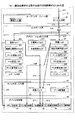
上記の操作は、ローカルUI部12の制御のもと、例えば、図7に示されるようなオペレーションパネルを介して行われる。
The above operation is performed under the control of the
図7は、オペレーションパネルにおけるフィルタの選択例を示す図である。図7において、オペレーションパネル202は、タッチパネル511とスタートボタン512とを含む。タッチパネル511は、タッチ操作で入力を行うためのハードウェア(タッチ操作部)であると共に、画面表示で出力を得るためのハードウェア(画面表示部)である。スタートボタン512は、要求した機能の実行開始指示を行うためのハードウェアである。
FIG. 7 is a diagram illustrating an example of filter selection on the operation panel. In FIG. 7, the
図7のタッチパネル511には、要求入力画面が表示されている。要求入力画面は、入力フィルタ選択領域513、変換フィルタ選択領域514、出力フィルタ選択領域515、及び要求表示領域516等より構成される。入力フィルタ選択領域513は、入力フィルタを選択させるための領域であり、入力フィルタごとにボタンが表示されている。入力フィルタ選択領域513でいずれかのボタンが選択されると、選択されたボタンに対応する入力フィルタのボタンが要求表示領域516に表示される。図中では、便宜上、読取フィルタ301及び保管文書読出フィルタ513のボタンが表示されている。
A request input screen is displayed on the
変換フィルタ選択領域514は、変換フィルタを選択させるための領域であり、変換フィルタごとにボタンが表示されている。変換フィルタ選択領域514でいずれかのボタンが選択されると、選択されたボタンに対応する変換フィルタのボタンが要求表示領域516に表示される。
The conversion
出力フィルタ選択領域515は、出力フィルタを選択させるための領域であり、出力フィルタごとにボタンが表示されている。出力フィルタ選択領域515でいずれかのボタンが選択されると、選択されたボタンに対応する出力フィルタのボタンが要求表示領域516に表示される。図中では、便宜上、印刷フィルタ321、保管文書登録フィルタ322、メール送信フィルタ323、及びFAX送信フィルタ324のボタンが表示されている。
The output
要求表示領域516には、入力フィルタ選択領域513、変換フィルタ選択領域514又は出力フィルタ選択領域515において選択されたフィルタのボタンが表示され、入力フィルタ、変換フィルタ、又は出力フィルタとの間は、データの流れ又はパイプを示す矢印で接続される。矢印を操作することにより、実行するフィルタの順番を変更することも可能である。要求表示領域516における表示内容によって、ユーザは、利用するフィルタとその流れを認識することができる。要求表示領域516には、更に、設定ボタン517及び削除ボタン518が配置されている。設定ボタン517は、要求表示領域516においてフィルタのボタンが選択されている場合に、当該フィルタの設定画面を表示させるためのボタンである。すなわち、設定ボタン517が押下(タッチ)されると、選択されているフィルタのフィルタ設定UIに基づいて、その設定画面がタッチパネル511に表示される。削除ボタン518は、要求表示領域516においてフィルタのボタンが選択されている場合に、当該フィルタの利用を解除するためのボタンである。
In the
なお、入力フィルタ、変換フィルタ、及び出力フィルタは、一つの機能に対してそれぞれ複数個の選択が可能である。例えば、スキャンされた画像と、複合機1内に保存されている画像を合成して、印刷すると共にFAX送信するといったような場合、少なくとも二つの入力フィルタ(読取フィルタ301及び保管文書読出フィルタ302)と二つの出力フィルタ(印刷フィルタ321及びFAX送信フィルタ324)とが選択される。
A plurality of input filters, conversion filters, and output filters can be selected for each function. For example, when the scanned image and the image stored in the
フィルタの選択が完了し(S106でYES)、スタートボタン512が押下されると、ユーザインタフェース層10からコントロール層20に対して、要求内容が通知される。
When the filter selection is completed (YES in S106) and the
図8は、ユーザインタフェース層からコントロール層へ通知される要求内容を概念的に示す図である。図8に示されるように、ユーザインタフェース層10からの要求は、ユーザインタフェース層10において選択されたフィルタごとに、フィルタの種別と当該フィルタに対する設定情報とを含むものであり、更にフィルタの実行順も含も含んでいる(図中において各ブロックを結ぶ矢印が、フィルタの実行順を示す)。
FIG. 8 is a diagram conceptually showing the request contents notified from the user interface layer to the control layer. As shown in FIG. 8, the request from the
図8に示されるような要求内容を受けて、コントロール層20は、選択された各フィルタより、当該フィルタが使用可能なパイプを示す情報(以下「使用可能パイプ情報」という。)を取得し、取得された使用可能パイプ情報に基づいて、フィルタ間をパイプによって接続する。
Upon receipt of the request content as shown in FIG. 8, the
図9は、使用可能パイプ情報の例を示す図である。図9の例によれば、読取フィルタ301は、出力側のパイプとして、DMA(Direct Memory Access)パイプ及び汎用メモリパイプを使用可能であることが示されている。DMAパイプとは、DMAを用いて高速にデータ転送を行うパイプである。汎用メモリパイプとは、有限サイズのRAMバッファによってデータ転送を行うパイプである。
FIG. 9 is a diagram illustrating an example of usable pipe information. According to the example of FIG. 9, it is shown that the
また、印刷フィルタ321は、入力側のパイプとして、DMAパイプ及び汎用メモリパイプが使用可能であることが示されている。また、PC文書受信フィルタ305は、出力側のパイプとしてスプールフィルタを使用可能であることが示されている。スプールパイプとは、HDDを用いるパイプであり、左側のフィルタから出力されたデータは、右側のフィルタが読み出すまでHDDにスプール(保存)される。また、文書変換フィルタ312は、入力側のパイプとして、スプールパイプ及び汎用メモリパイプが使用可能であり、出力側のパイプとして、スプールパイプ、DMAパイプ、及び汎用メモリパイプが使用可能であることが示されている。
Further, it is shown that the
図9は、表形式によって表現されているが、これは、当該表形式の状態で情報が保存されていることを示すものではない。図9において行単位の使用可能パイプ情報が、それぞれのフィルタより取得されることを意味する。使用可能パイプ情報は、例えば、永続記憶領域情報(図3参照)の一部として各フィルタに含まれている。 Although FIG. 9 is expressed in a table format, this does not indicate that information is stored in the state of the table format. In FIG. 9, it means that the usable pipe information for each row is acquired from each filter. The usable pipe information is included in each filter as a part of the permanent storage area information (see FIG. 3), for example.
また、図9において空欄となっている箇所については、パイプが使用されないことを示す。例えば、読取フィルタ301にはパイプからではなく、スキャナから画像データが入力されるからである。
In addition, a portion that is blank in FIG. 9 indicates that a pipe is not used. For example, image data is input to the
なお、図1における画像パイプ41は、上記の各種のパイプへのインタフェースを提供するモジュールを抽象的に表現したものである。
The
図9に示されるような使用可能パイプ情報に基づいて、コントロール層20は、接続される一方のフィルタの出力側に使用可能なパイプと、他方のフィルタの入力側に使用可能なパイプとを比較することで、双方を接続可能なパイプを判定し、接続可能であると判定されたパイプを複合機1において使用可能な(有効な)パイプの中から検索する(S107)。例えば、読取フィルタ301と印刷フィルタ321とを接続しようとする場合、読取フィルタ301の出力側に使用可能なパイプと、印刷フィルタ321の入力側に使用可能なパイプとを比較することにより、DMAパイプと汎用メモリパイプが接続可能なパイプとして検索される。
Based on the usable pipe information as shown in FIG. 9, the
双方のフィルタにおいて共通に使用可能なパイプが有り、当該パイプが複合機1内より検索された場合(S108でYES)、コントロール層20は、検索されたパイプによってフィルタ間を接続する(S109)。
When there is a pipe that can be used in common in both filters, and the pipe is searched from within the multi function device 1 (YES in S108), the
図10は、コントロール層によって生成される情報を概念的に示す図である。図10では、各フィルタ(「F」)間がパイプ(「P」)によって接続されている様子が示されている。 FIG. 10 is a diagram conceptually showing information generated by the control layer. FIG. 10 shows a state in which the filters (“F”) are connected by pipes (“P”).
なお、読取フィルタ301と印刷フィルタ321との組み合わせのように、接続可能なパイプが複数存在する可能性がある。したがって、斯かる場合を考慮して、パイプに優先順位を設け、優先順位の高いパイプを選択するようにしてもよい。例えばDMAのように高速な転送方式の優先度を高くしておけば、汎用メモリに対してDMAパイプが優先的に選択される。また、接続可能であると判定された複数のパイプの中から利用するパイプを選択させる画面をオペレーションパネル202に表示し、当該画面においてユーザに選択させるようにしてもよい。
Note that there may be a plurality of connectable pipes such as a combination of the read
一方、双方のフィルタにおいて共通に使用可能なパイプが無かった場合、又は、接続可能なパイプは有っても、当該パイプが複合機1に存在しない場合は(S109でNO)、選択されたフィルタが組み合わせ不可能であることをユーザに通知する(オペレーションパネル202に表示させる)ようにしてもよい。例えば、PC受信文書フィルタ305と印刷フィルタ321とを接続しようとした場合、PC受信文書フィルタ305の出力側にはスプールパイプのみが使用可能であるのに対し、印刷フィルタ321の入力側に使用可能なパイプはDMAパイプと汎用メモリパイプであるため、双方を接続可能なパイプが存在しない。
On the other hand, if there is no pipe that can be used in common in both filters, or if there is a pipe that can be connected but the pipe does not exist in the multifunction machine 1 (NO in S109), the selected filter May be notified to the user (displayed on the operation panel 202). For example, when trying to connect the PC received
続いて、コントロール層20は、各フィルタに対して並列的に実行要求を出力する(S110)。すなわち、フィルタの呼び出しはフィルタの接続順ではなく、全てのフィルタに対してほぼ同時に行われる。フィルタ間の同期はパイプによってとられるからである。すなわち、コントロール層からの実行要求を受けて、各フィルタは自分の入力側のパイプにデータが入力されるまで待機する。但し、入力フィルタには、入力側にパイプは存在しない。したがって、入力フィルタは実行要求に応じて処理を開始する。
Subsequently, the
まず、入力フィルタは、入力デバイスよりデータを入力し(図6のS111)、当該データを、出力側に接続されているパイプに出力する(S112)。なお、データが複数回に分けて入力される場合(複数枚の原稿がスキャンされる場合等)は、データの入力とパイプへの出力が繰り返される。全ての入力データについて処理が終了すると(S113でYES)、入力フィルタの処理は終了する。 First, the input filter inputs data from the input device (S111 in FIG. 6), and outputs the data to a pipe connected to the output side (S112). When data is input in a plurality of times (for example, when a plurality of documents are scanned), data input and output to a pipe are repeated. When the process is completed for all input data (YES in S113), the input filter process ends.
変換フィルタは、入力側に接続されているパイプに対するデータの入力を検知すると処理を開始する。まず、当該パイプからデータを読み込み(S121)、データに対して画像処理を施す(S122)。続いて、処理結果としてのデータを出力側に接続されているパイプに出力する(S123)。入力側のパイプに入力された全てのデータについて処理が終了すると(S124でYES)、変換フィルタの処理は終了する。 The conversion filter starts processing when it detects data input to a pipe connected to the input side. First, data is read from the pipe (S121), and image processing is performed on the data (S122). Subsequently, the data as the processing result is output to the pipe connected to the output side (S123). When the processing is completed for all data input to the input side pipe (YES in S124), the conversion filter processing ends.
出力フィルタは、入力側に接続されているパイプに対するデータの入力を検知すると処理を開始する。まず、当該パイプからデータを読み込み(S131)。続いて、読み込まれたデータを出力デバイスを利用して出力する(S132)。入力側のパイプに入力された全てのデータについて処理が終了すると(S133でYES)、出力フィルタの処理は終了する。 The output filter starts processing when it detects data input to the pipe connected to the input side. First, data is read from the pipe (S131). Subsequently, the read data is output using an output device (S132). When the process is completed for all data input to the input side pipe (YES in S133), the output filter process ends.
ところで、本実施の形態では、図9に示されるような使用可能パイプ情報に基づいてフィルタ間を接続するパイプが判定される例について説明したが、予め、フィルタ同士の組み合わせごとに、接続されるパイプを予め定義しておきき、その定義情報を図11に示されるようなテーブルにおいて一元的に管理してくことも考えられる。 By the way, in this Embodiment, although the example in which the pipe which connects between filters was determined based on usable pipe information as shown in FIG. 9 was demonstrated, it connects for every combination of filters beforehand. It is also conceivable to define pipes in advance and manage the definition information in a centralized manner in a table as shown in FIG.
図11は、フィルタとパイプの対応テーブルの例を示す図である。図11の対応テーブル60によれば、例えば、読取フィルタ301と印刷フィルタ321や、文書変換フィルタ312と印刷フィルタ321は、DMAパイプによって接続可能であることが示されている。また、PC文書受信フィルタ305と文書変換フィルタ312とは、スプールパイプによって接続可能であることが示されている。
FIG. 11 is a diagram illustrating an example of a correspondence table between filters and pipes. According to the correspondence table 60 of FIG. 11, for example, it is indicated that the reading
斯かる対応テーブル60を参照することによって、コントロール層20が、フィルタ間を接続するパイプを判定することもできる。しかし、この場合、フィルタ間を接続可能なパイプとして新たなパイプを追加したいときや、新たなフィルタが複合機1に追加され、当該新たなフィルタに関する接続関係を追加したいとき等、フィルタやパイプの構成の変化に応じて対応テーブル60も更新しなければならない。斯かる状態は、フィルタ間の独立性を損ね、カスタマイズ性の向上の足かせになってしまうおそれがある。
By referring to such a correspondence table 60, the
一方、本実施の形態のように、使用可能パイプ情報がフィルタごとに管理されている形態によれば、既存の管理情報を更新することなく、フィルタ間を接続するパイプを動的に判定することができる。したがって、フィルタ間の独立性を高めることができ、高いカスタマイズ性を提供することができる。 On the other hand, according to the form in which usable pipe information is managed for each filter as in the present embodiment, the pipes connecting the filters are dynamically determined without updating the existing management information. Can do. Therefore, the independence between the filters can be increased, and high customization can be provided.
次に、具体的な機能を例として、複合機1内における処理シーケンスを説明する。図12は、コピー機能を実現する際の処理手順を説明するための図である。
Next, taking a specific function as an example, a processing sequence in the
ステップS11において、ローカルUI部12は、図7に示したオペレーションパネルを介してユーザからコピー要求の入力(フィルタの選択)を受け付ける。
In step S11, the
ところで、図7に示されるようにユーザに各フィルタを選択させるといったユーザインタフェースは、ユーザの要求に柔軟に対応できるという反面、コピーのように頻繁に利用する機能については、毎回フィルタの選択によって実行指示を行うのはユーザにとって煩雑である。そこで、例えば、頻繁に利用する機能については、「コピー」ボタンを表示させ、「コピー」ボタンが選択されると、内部的に利用するフィルタが選択されるようにしてもよい。 By the way, the user interface that allows the user to select each filter as shown in FIG. 7 can flexibly respond to the user's request, but frequently used functions such as copying are executed by selecting the filter every time. The instruction is complicated for the user. Thus, for example, for a frequently used function, a “copy” button may be displayed, and when the “copy” button is selected, an internally used filter may be selected.
ユーザによって要求が入力されると、ローカルUI部12は、入力された要求(選択されたフィルタ)の実行をコントロール層20に要求する(S12)。コントロール層20は、選択されたフィルタ間をパイプによって接続する(S13)。
When a request is input by the user, the
図13は、コピー機能に係るフィルタ間がパイプによって接続された様子を概念的に示す図である。図13において、読取フィルタ301と印刷フィルタ321とが画像パイプ41によって接続されている。ステップS13では、このような内容を示す情報が生成される。図9より、ここでの画像パイプ41は、DMAパイプ又は汎用メモリパイプが相当する。
FIG. 13 is a diagram conceptually illustrating a state in which filters related to the copy function are connected by a pipe. In FIG. 13, a
続いて、コントロール層20は、利用する各フィルタ(読取フィルタ301及び印刷フィルタ321)に対して実行要求を並列的に出力する(S14)。
Subsequently, the
まず、入力フィルタである読取フィルタ301は、スキャナ制御部51に対して画像の読み取りを指示する(S15)。当該指示に応じてスキャナ制御部51の制御のもと、スキャナ(撮像部)によって原稿から画像データが読み取られ、読取フィルタ301に出力される。読取フィルタ301は、当該画像データを画像パイプ41に出力する(S16)。画像パイプ41の実体はメモリであるため、画像パイプ41は、メモリ制御部53を介して画像データをメモリに書き込む(S17)。なお、ここでは、DMA転送が行われる。
First, the reading
一方、印刷フィルタ321は、入力側に接続されている画像パイプ41への画像データの書き込みが検知されると処理を開始する。まず、印刷フィルタ321は、画像パイプ41に対し画像データの読み込みを要求する(S18)。画像パイプ41は、メモリ制御部53を介して画像データを読み込む(S19)。印刷フィルタ321は、当該画像データの印刷をプロッタ制御部52に指示する(S20)。当該指示に応じてメモリ制御部53からプロッタ制御部52に画像データがDMA転送され、プロッタ制御部52の制御のもと、プロッタ(印刷部)によって画像データが印刷される。
On the other hand, the
次に、プリンタ機能(クライアントPCからの印刷機能)について説明する。図14は、プリンタ機能を実現する際の処理手順を説明するための図である。 Next, the printer function (print function from the client PC) will be described. FIG. 14 is a diagram for explaining a processing procedure for realizing the printer function.
ステップS21において、クライアントPCからの印刷要求が受け付けられる。当該印刷要求は、まず、ネットワーク制御部55によって受信され、通信サーバ部11に通知される。通信サーバ部11は、プリンタ機能を実現するために必要なフィルタを選択し、選択されたフィルタの実行をコントロール層20に要求する(S22)。コントロール層20は、選択されたフィルタ間をパイプによって接続する(S23)。
In step S21, a print request from the client PC is accepted. The print request is first received by the
図15は、プリンタ機能に係るフィルタ間がパイプによって接続された様子を概念的に示す図である。図15において、PC文書受信フィルタ305と文書変換フィルタ312とが画像パイプ41によって接続されている。また、文書変換フィルタ312と印刷フィルタ321とも画像パイプ41によって接続されている。図9より、PC文書受信フィルタ305と文書変換フィルタ312との間の画像パイプ41は、スプールパイプが相当する。また、文書変換フィルタ312と印刷フィルタ321との間の画像パイプ41は、DMAパイプが相当する。
FIG. 15 is a diagram conceptually illustrating a state in which filters related to the printer function are connected by a pipe. In FIG. 15, a PC
続いて、コントロール層20は、利用する各フィルタ(PC文書受信フィルタ305、文書変換フィルタ312、及び印刷フィルタ321)に対して実行要求を並列的に出力する(S24)。
Subsequently, the
まず、入力フィルタであるPC文書受信フィルタ305は、ネットワーク制御部55に対して印刷データ(PDL)の受信を指示する(S25)。印刷データが受信されると、PC文書受信フィルタ305は、受信された印刷データを画像パイプ41に出力する(S26)、画像パイプ41は、メモリ制御部53を介して印刷データをメモリ(ここではHDD)に書き込む(S27)。
First, the PC
文書変換フィルタ312は、入力側に接続されている画像パイプ41への印刷データの書き込みが検知されると処理を開始する。まず、文書変換フィルタ312は、画像パイプ41に対し印刷データの読み込みを要求する(S28)。画像パイプ41は、メモリ制御部53を介してHDDより印刷データを読み込み(S29)、文書変換フィルタ312に出力する。文書変換フィルタ312は、当該印刷データを画像データ(ビットマップ)に変換し(S30)、当該画像データを画像パイプ41に出力する(S31)。続いて、画像パイプ41は、メモリ制御部53を介して画像データをメモリに書き込む(S32)。
The
印刷フィルタ321は、入力側に接続されている画像パイプ41への画像データの書き込みが検知されると処理を開始する。まず、印刷フィルタ321は、画像パイプ41に対し画像データの読み込みを要求する(S33)。画像パイプ41は、メモリ制御部53を介して画像データを読み込む(S34)。印刷フィルタ321は、当該画像データの印刷をプロッタ制御部52に指示する(S35)。当該指示に応じてメモリ制御部53からプロッタ制御部52に画像データがDMA転送され、プロッタ制御部52の制御のもと、プロッタ(印刷部)によって画像データが印刷される。
The
なお、他の機能についても同様のシーケンスによって実現される。 Other functions are also realized by the same sequence.
上述したように本実施の形態における複合機1によれば、各フィルタを部品として各機能を構築するため、機能のカスタマイズ又は拡張を簡便に行うことができる。すなわち、各フィルタ間には、機能的な依存関係はなく独立性が保たれているため、フィルタの新たな追加やフィルタの組み合わせの変更によって、新たな機能(アプリケーション)を容易に開発することができる。したがって、新たなアプリケーションの実装が要求された場合、当該アプリケーションの一部の処理について実装されていない場合は、当該一部の処理を実現するフィルタのみを開発し、インストールすればよい。よって、コントロール層20及びアプリケーションロジック層30より下位の層について、新たなアプリケーションの実装に応じて発生する修正の頻度を低下させることができ、安定したプラットフォームを提供することができる。
As described above, according to the
また、フィルタ単位で実行条件の設定用のユーザインタフェースが実装されるため、或るフィルタを用いて実現されるアプリケーション間では、当該フィルタのユーザインタフェースを共通的に用いることができ、アプリケーションごとのユーザインタフェースの開発工数を削減することができる。 In addition, since a user interface for setting execution conditions is implemented for each filter, the user interface of the filter can be used in common between applications realized using a certain filter. Interface development man-hours can be reduced.
なお、本実施の形態において、画像パイプ41は、伝達手段の一例に相当する。また、コントロール層20は、判定手段の一例に相当する。
In the present embodiment, the
ところで、以下に複合機1のハードウェア構成の一例を示す。図16は、本発明の実施の形態における複合機のハードウェア構成の一例を示す図である。
An example of the hardware configuration of the
複合機1のハードウェアとしては、コントローラ201と、オペレーションパネル202と、ファクシミリコントロールユニット(FCU)203と、撮像部121と、印刷部122が存在する。
As hardware of the
コントローラ201は、CPU211、ASIC212、NB221、SB222、MEM−P231、MEM−C232、HDD(ハードディスクドライブ)233、メモリカードスロット234、NIC(ネットワークインタフェースコントローラ)241、USBデバイス242、IEEE1394デバイス243、セントロニクスデバイス244により構成される。
The
CPU211は、種々の情報処理用のICである。ASIC212は、種々の画像処理用のICである。NB221は、コントローラ201のノースブリッジである。SB222は、コントローラ201のサウスブリッジである。MEM−P231は、複合機1のシステムメモリである。MEM−C232は、複合機1のローカルメモリである。HDD233は、複合機1のストレージである。メモリカードスロット234は、メモリカード235をセットするためのスロットである。NIC241は、MACアドレスによるネットワーク通信用のコントローラである。USBデバイス242は、USB規格の接続端子を提供するためのデバイスである。IEEE1394デバイス243は、IEEE1394規格の接続端子を提供するためのデバイスである。セントロニクスデバイス244は、セントロニクス仕様の接続端子を提供するためのデバイスである。オペレーションパネル202は、オペレータが複合機1に入力を行うためのハードウェア(操作部)であると共に、オペレータが複合機1から出力を得るためのハードウェア(表示部)である。
The
なお、図1に示されるソフトウェアは、例えば、MEM−C232に格納され、CPU211によって処理されることによりその機能を複合機に実行させる。
Note that the software shown in FIG. 1 is stored in, for example, the MEM-
以上、本発明の実施例について詳述したが、本発明は係る特定の実施形態に限定されるものではなく、特許請求の範囲に記載された本発明の要旨の範囲内において、種々の変形・変更が可能である。 As mentioned above, although the Example of this invention was explained in full detail, this invention is not limited to the specific embodiment which concerns, In the range of the summary of this invention described in the claim, various deformation | transformation * It can be changed.
1 複合機
10 ユーザインタフェース層
11 通信サーバ部
12 ローカルUI部
20 コントロール層
30 アプリケーションロジック層
40 デバイスサービス層
41 画像パイプ
42 データ管理部
50 デバイス制御層
51 スキャナ制御部
52 プロッタ制御部
53 メモリ制御部
54 Tel回線制御部
55 ネットワーク制御部
60 対応テーブル
201 コントローラ
202 オペレーションパネル
203 ファクシミリコントロールユニット
211 CPU
212 ASIC
221 NB
222 SB
231 MEM−P
232 MEM−C
233 HDD
234 メモリカードスロット
235 メモリカード
241 NIC
242 USBデバイス
243 IEEE1394デバイス
244 セントロニクスデバイス
301 読取フィルタ
302 保管文書読出フィルタ
303 メール受信フィルタ
304 FAX受信フィルタ
305 PC文書受信フィルタ
306 レポートフィルタ
311 文書変換フィルタ
312 文書変換フィルタ
321 印刷フィルタ
322 保管文書登録フィルタ
323 メール送信フィルタ
324 FAX送信フィルタ
325 PC文書送信フィルタ
326 プレビューフィルタ
1
212 ASIC
221 NB
222 SB
231 MEM-P
232 MEM-C
233 HDD
234
242
Claims (10)
該画像処理の結果を出力する一つ以上の出力部と、
前記入力部に応じて当該入力部からのデータの入力処理を制御するソフトウェア部品である複数の第一のフィルタと、
前記出力部に応じて当該出力部への出力を制御するソフトウェア部品である複数の第二のフィルタと、
複数の中からユーザによって選択された、一以上の前記第一のフィルタと一以上の前記第二のフィルタとの接続によりアプリケーションを構築する構築手段とを有し、
前記構築手段は、前記第一のフィルタと前記第二のフィルタとの間を、当該フィルタ間においてデータを伝達する伝達手段、又は他のフィルタ及び当該他のフィルタをも含むフィルタ間においてデータを伝達する前記伝達手段によって接続し、前記フィルタごとに含まれている当該フィルタが使用可能な伝達手段を示す情報に基づいて、前記第一のフィルタと前記第二のフィルタとの間を接続可能な前記伝達手段を判定することを特徴とする画像形成装置。 One or more input units for inputting data to be subjected to image processing;
One or more output units for outputting the result of the image processing;
A plurality of first filters, which are software components that control input processing of data from the input unit according to the input unit;
A plurality of second filters that are software components that control the output to the output unit according to the output unit;
Construction means for constructing an application by connecting one or more of the first filters and one or more of the second filters selected by the user from a plurality of;
The construction means transmits the data between the first filter and the second filter between the filters, or between the filters including the other filters and the other filters. the connected by transmission means, said based on the filter information indicating the transmission means available that are included in each filter, connectable between said second filter and said first filter said to An image forming apparatus characterized by determining a transmission means.
前記構築手段は、前記選択手段が選択させた一以上の前記第一のフィルタと一以上の前記第二のフィルタとの間を、前記伝達手段によって接続することにより前記アプリケーションを構築する請求項1記載の画像形成装置。 Let the user select one or more of the first filters and one or more of the second filters that construct the application from among the plurality of first filters and the plurality of second filters via a screen. Having a selection means,
The construction unit, according to claim wherein said selection means between said one or more obtained by selecting the first filter and one or more of the second filter, to build more the application to be connected by said transmission means The image forming apparatus according to 1.
前記構築手段は、前記第一のフィルタと前記第三のフィルタとの間を前記伝達手段によって接続し、前記第三のフィルタと前記第二のフィルタとの間を前記伝達手段によって接続することにより前記アプリケーションを構築することを特徴とする請求項1又は2記載の画像形成装置。 A third filter that is a software component that executes the image processing according to the type of the image processing;
The construction means connects the first filter and the third filter by the transmission means, and connects the third filter and the second filter by the transmission means. The image forming apparatus according to claim 1, wherein the application is constructed.
該画像処理の結果を出力する一つ以上の出力部と、
前記入力部に応じて当該入力部からのデータの入力処理を制御するソフトウェア部品である複数の第一のフィルタと、
前記出力部に応じて当該出力部への出力を制御するソフトウェア部品である複数の第二のフィルタとを有する画像形成装置が実行するアプリケーション構築方法であって、
複数の中からユーザによって選択された、一以上の前記第一のフィルタと一以上の前記第二のフィルタとの接続によりアプリケーションを構築する構築手順を有し、
前記構築手順は、前記第一のフィルタと前記第二のフィルタとの間を、当該フィルタ間においてデータを伝達する伝達手段、又は他のフィルタ及び当該他のフィルタをも含むフィルタ間においてデータを伝達する前記伝達手段によって接続し、前記フィルタごとに含まれている当該フィルタが使用可能な伝達手段を示す情報に基づいて、前記第一のフィルタと前記第二のフィルタとの間を接続可能な前記伝達手段を判定することを特徴とするアプリケーション構築方法。 One or more input units for inputting data to be subjected to image processing;
One or more output units for outputting the result of the image processing;
A plurality of first filters, which are software components that control input processing of data from the input unit according to the input unit;
An application construction method executed by an image forming apparatus having a plurality of second filters, which are software components that control output to the output unit according to the output unit,
A construction procedure for constructing an application by connecting one or more of the first filters and one or more of the second filters selected by the user from a plurality of;
In the construction procedure, data is transmitted between the first filter and the second filter, and between the filters including the other filters and the other filters. the connected by transmission means, said based on the filter information indicating the transmission means available that are included in each filter, connectable between said second filter and said first filter said to An application construction method characterized by determining a transmission means.
前記構築手順は、前記選択手順が選択させた一以上の前記第一のフィルタと一以上の前記第二のフィルタと間を、前記伝達手段によって接続することにより前記アプリケーションを構築する請求項6記載のアプリケーション構築方法。 Let the user select one or more of the first filters and one or more of the second filters that construct the application from among the plurality of first filters and the plurality of second filters via a screen. Has a selection procedure,
The construction procedure is claim to build more the application that between said selection procedure is one or more of the first filter and one or more of the second, which is selective filter, connected by the transmission means 6 The application construction method described.
前記構築手順は、前記第一のフィルタと前記第三のフィルタとの間を前記伝達手段によって接続し、前記第三のフィルタと前記第二のフィルタとの間を前記伝達手段によって接続することにより前記アプリケーションを構築することを特徴とする請求項6又は7記載のアプリケーション構築方法。 The image forming apparatus includes a third filter that is a software component that executes the image processing according to the type of the image processing.
In the construction procedure, the first filter and the third filter are connected by the transmission means, and the third filter and the second filter are connected by the transmission means. 8. The application construction method according to claim 6, wherein the application is constructed.
Priority Applications (1)
| Application Number | Priority Date | Filing Date | Title |
|---|---|---|---|
| JP2007143644A JP4922836B2 (en) | 2007-05-30 | 2007-05-30 | Image forming apparatus and application construction method |
Applications Claiming Priority (1)
| Application Number | Priority Date | Filing Date | Title |
|---|---|---|---|
| JP2007143644A JP4922836B2 (en) | 2007-05-30 | 2007-05-30 | Image forming apparatus and application construction method |
Publications (2)
| Publication Number | Publication Date |
|---|---|
| JP2008301073A JP2008301073A (en) | 2008-12-11 |
| JP4922836B2 true JP4922836B2 (en) | 2012-04-25 |
Family
ID=40174184
Family Applications (1)
| Application Number | Title | Priority Date | Filing Date |
|---|---|---|---|
| JP2007143644A Expired - Fee Related JP4922836B2 (en) | 2007-05-30 | 2007-05-30 | Image forming apparatus and application construction method |
Country Status (1)
| Country | Link |
|---|---|
| JP (1) | JP4922836B2 (en) |
Families Citing this family (1)
| Publication number | Priority date | Publication date | Assignee | Title |
|---|---|---|---|---|
| JP5293238B2 (en) * | 2009-02-03 | 2013-09-18 | 株式会社リコー | Information processing apparatus, image forming apparatus, and program installation method |
Family Cites Families (3)
| Publication number | Priority date | Publication date | Assignee | Title |
|---|---|---|---|---|
| JP3358142B2 (en) * | 1992-06-23 | 2002-12-16 | 博文 松尾 | Object identification system |
| JP2002202946A (en) * | 2000-12-28 | 2002-07-19 | Ricoh Co Ltd | Digital image processor |
| JP2006154949A (en) * | 2004-11-25 | 2006-06-15 | Canon Inc | Multi-functional print method and multi-functional printer |
-
2007
- 2007-05-30 JP JP2007143644A patent/JP4922836B2/en not_active Expired - Fee Related
Also Published As
| Publication number | Publication date |
|---|---|
| JP2008301073A (en) | 2008-12-11 |
Similar Documents
| Publication | Publication Date | Title |
|---|---|---|
| JP4861883B2 (en) | Image forming apparatus and application execution method | |
| US20090164927A1 (en) | Image processing apparatus and method thereof | |
| JP5704800B2 (en) | Data processing apparatus, data processing method, and program | |
| JP2011065655A (en) | Image processing apparatus | |
| JP2010021896A (en) | Information processing apparatus, image input apparatus, document distribution system, and control method therefor | |
| JP2009111904A (en) | Device for processing images and method of executing applications | |
| US20070229871A1 (en) | Image processing device, and control method of image processing device | |
| US8395796B2 (en) | Information processing apparatus, image processing apparatus, information processing method, and information processing program which outputs information in the form of a report | |
| JP2005322971A (en) | Information processing system, and information processing method and program used for information processing system | |
| JP5145871B2 (en) | Image processing apparatus and application execution method | |
| JP2008305004A (en) | Image forming apparatus, application execution method, and application execution program | |
| JP2004171515A (en) | Image forming apparatus and image data transfer method | |
| US20100202007A1 (en) | Image processing apparatus, control method thereof, and computer program | |
| JP2011103664A (en) | Image forming device | |
| US20080168441A1 (en) | Data processing apparatus, image processing apparatus, data processing method, and computer-readable recording medium | |
| US20090103828A1 (en) | Image Processing Apparatus, Image Processing Method, and Computer-Readable Recording Medium Having Image Processing Program | |
| JP4922836B2 (en) | Image forming apparatus and application construction method | |
| JP2007067807A (en) | Data transmission device, data transmission method and program | |
| US20090064201A1 (en) | Image Forming Apparatus, Application Management Method, and Computer-Readable Recording Medium Having Application Management Program | |
| JP4895928B2 (en) | Image processing apparatus, application execution method, and application execution program | |
| JP2010141790A (en) | Image processing apparatus, workflow executing method, and program | |
| JP2010198316A (en) | Image processing system, image processing apparatus, image forming apparatus, image processing method, and image processing program | |
| JP2005287042A (en) | Apparatus, method and program for image formation | |
| JP5037271B2 (en) | Image forming apparatus, information processing method, and information processing program | |
| JP5315919B2 (en) | Image forming apparatus, image forming control method, and image forming control program |
Legal Events
| Date | Code | Title | Description |
|---|---|---|---|
| A621 | Written request for application examination |
Free format text: JAPANESE INTERMEDIATE CODE: A621 Effective date: 20090828 |
|
| A977 | Report on retrieval |
Free format text: JAPANESE INTERMEDIATE CODE: A971007 Effective date: 20110222 |
|
| A131 | Notification of reasons for refusal |
Free format text: JAPANESE INTERMEDIATE CODE: A131 Effective date: 20110329 |
|
| A521 | Written amendment |
Free format text: JAPANESE INTERMEDIATE CODE: A523 Effective date: 20110425 |
|
| A131 | Notification of reasons for refusal |
Free format text: JAPANESE INTERMEDIATE CODE: A131 Effective date: 20111025 |
|
| A521 | Written amendment |
Free format text: JAPANESE INTERMEDIATE CODE: A523 Effective date: 20111209 |
|
| TRDD | Decision of grant or rejection written | ||
| A01 | Written decision to grant a patent or to grant a registration (utility model) |
Free format text: JAPANESE INTERMEDIATE CODE: A01 Effective date: 20120110 |
|
| A01 | Written decision to grant a patent or to grant a registration (utility model) |
Free format text: JAPANESE INTERMEDIATE CODE: A01 |
|
| A61 | First payment of annual fees (during grant procedure) |
Free format text: JAPANESE INTERMEDIATE CODE: A61 Effective date: 20120206 |
|
| R150 | Certificate of patent or registration of utility model |
Ref document number: 4922836 Country of ref document: JP Free format text: JAPANESE INTERMEDIATE CODE: R150 Free format text: JAPANESE INTERMEDIATE CODE: R150 |
|
| FPAY | Renewal fee payment (event date is renewal date of database) |
Free format text: PAYMENT UNTIL: 20150210 Year of fee payment: 3 |
|
| LAPS | Cancellation because of no payment of annual fees |