JP4921142B2 - Communication device - Google Patents
Communication device Download PDFInfo
- Publication number
- JP4921142B2 JP4921142B2 JP2006334787A JP2006334787A JP4921142B2 JP 4921142 B2 JP4921142 B2 JP 4921142B2 JP 2006334787 A JP2006334787 A JP 2006334787A JP 2006334787 A JP2006334787 A JP 2006334787A JP 4921142 B2 JP4921142 B2 JP 4921142B2
- Authority
- JP
- Japan
- Prior art keywords
- recording means
- control information
- data
- pcb
- protocol processing
- Prior art date
- Legal status (The legal status is an assumption and is not a legal conclusion. Google has not performed a legal analysis and makes no representation as to the accuracy of the status listed.)
- Expired - Fee Related
Links
- 238000004891 communication Methods 0.000 title claims description 30
- 238000012545 processing Methods 0.000 claims description 57
- 230000005540 biological transmission Effects 0.000 claims description 29
- 238000012546 transfer Methods 0.000 claims description 8
- 150000003071 polychlorinated biphenyls Chemical class 0.000 description 14
- 238000000034 method Methods 0.000 description 9
- 238000007781 pre-processing Methods 0.000 description 9
- 230000008569 process Effects 0.000 description 8
- 230000008859 change Effects 0.000 description 7
- 238000010586 diagram Methods 0.000 description 7
- 230000006870 function Effects 0.000 description 7
- 238000012805 post-processing Methods 0.000 description 6
- 238000012217 deletion Methods 0.000 description 5
- 230000037430 deletion Effects 0.000 description 5
- 230000009471 action Effects 0.000 description 2
- 230000000694 effects Effects 0.000 description 2
- 238000012986 modification Methods 0.000 description 2
- 230000004048 modification Effects 0.000 description 2
- 239000012634 fragment Substances 0.000 description 1
- 230000007246 mechanism Effects 0.000 description 1
- 230000003287 optical effect Effects 0.000 description 1
- 230000008707 rearrangement Effects 0.000 description 1
- 230000007704 transition Effects 0.000 description 1
Images


Classifications
-
- H—ELECTRICITY
- H04—ELECTRIC COMMUNICATION TECHNIQUE
- H04L—TRANSMISSION OF DIGITAL INFORMATION, e.g. TELEGRAPHIC COMMUNICATION
- H04L69/00—Network arrangements, protocols or services independent of the application payload and not provided for in the other groups of this subclass
- H04L69/16—Implementation or adaptation of Internet protocol [IP], of transmission control protocol [TCP] or of user datagram protocol [UDP]
- H04L69/161—Implementation details of TCP/IP or UDP/IP stack architecture; Specification of modified or new header fields
- H04L69/162—Implementation details of TCP/IP or UDP/IP stack architecture; Specification of modified or new header fields involving adaptations of sockets based mechanisms
Description
本発明は、PCB(プロトコル制御ブロック)等のプロトコル制御情報を用いてプロトコル処理を行う技術に関するものである。 The present invention relates to a technique for performing protocol processing using protocol control information such as PCB (protocol control block).
ギガビットイーサネット(登録商標)等の普及により汎用PCのみならず、組み込み機器においてもネットワークプロトコル処理を高速に実行できることが要求されている。 With the widespread use of Gigabit Ethernet (registered trademark) and the like, not only general-purpose PCs but also embedded devices are required to be able to execute network protocol processing at high speed.
ところで、ギガビットイーサネット(登録商標)のFull-wireの速度を達成するためには、動作周波数3GHz程度のプロセッサが必要になると言われている。これは、今日の組み込み機器が一般的に搭載するプロセッサ能力をはるかに超えている。そこで、TOE(TCP/IPオフロードエンジン)といったプロトコル処理に特化した補助的デバイスをシステムに付加し、広帯域なネットワーク通信を実現することが一般的になりつつある。TOEの従来技術の一例が特許文献1に開示されている。
By the way, it is said that a processor having an operating frequency of about 3 GHz is required to achieve the full-wire speed of Gigabit Ethernet (registered trademark). This is far beyond the processor capabilities that today's embedded devices typically have. Therefore, it is becoming common to add an auxiliary device specialized for protocol processing such as TOE (TCP / IP offload engine) to the system to realize broadband network communication. An example of the prior art of TOE is disclosed in
さて、TCPのプロトコル処理において重要となるのはPCBの扱いである。PCBとは、プロトコル制御ブロックの略称である。PCBは、TCPコネクション毎に用意されている、数十種類のパラメータ(変数)で構成されるコンテキスト情報であり、TCPパケットを受信する度にどのPCB情報を使うかを検索し、決定する必要がある。 Now, what is important in TCP protocol processing is PCB handling. PCB is an abbreviation for protocol control block. The PCB is context information composed of several tens of parameters (variables) prepared for each TCP connection, and it is necessary to search and determine which PCB information is used every time a TCP packet is received. is there.
また、PCBの各要素は、TCP処理中に頻繁にアクセスされる変数であり、TCP処理においては要になる変数である。TCPの高速化において、PCBの検索とアクセスの高速化が必須とされている。 Each element of the PCB is a variable that is frequently accessed during the TCP process, and is a variable that is essential in the TCP process. In speeding up TCP, it is essential to speed up PCB search and access.
特許文献1に開示される発明においては、TCPプロトコル処理を行うのに必要なPCBを主記憶からSRAM等の高速な一時メモリにコピーして保持することによりアクセスの高速化を実現している。このとき、コネクションの数が増え、全てのPCBが一時メモリに収まらない場合は、必要なPCBのみ一時メモリに存在するように主記憶との間で入れ替え処理を行っている。
In the invention disclosed in
前述のように、PCBを高速な一時メモリに格納して処理することによりプロトコルスタック処理を高速化させることができる。しかしながら、処理性能を考えるときには、一時メモリ中のPCBの入れ替え処理の影響を考慮しなければならない。一時メモリ中のPCBの入れ替えは、一時メモリの容量がコネクション数に比べ小さい場合に頻発する。この問題は、特に組込み系のシステムではコスト面から一時メモリ容量を大きくすることができないため深刻である。 As described above, the protocol stack processing can be accelerated by storing the PCB in a high-speed temporary memory and processing it. However, when considering processing performance, it is necessary to consider the effect of PCB replacement processing in the temporary memory. The replacement of the PCB in the temporary memory frequently occurs when the capacity of the temporary memory is smaller than the number of connections. This problem is particularly serious in an embedded system because the temporary memory capacity cannot be increased from the viewpoint of cost.
一時メモリの入れ替えには、一時メモリ中に存在するPCBのうちの一つを選択し、それを主記憶部に書き戻し、その後、新たに必要となったPCBを読み出すことになる。PCBのデータ量は100数十バイトに及ぶため、この一時メモリ入れ替えの時間が性能に与える影響は大きく、この時間を短縮することが課題となっている。 To replace the temporary memory, one of the PCBs existing in the temporary memory is selected, written back to the main memory, and then the newly required PCB is read. Since the amount of data on the PCB reaches 100 and several tens of bytes, the temporary memory replacement time has a large influence on the performance, and it is an issue to reduce this time.
そこで、本発明の目的は、書き戻すデータ量を削減し、プロトコル制御情報の書き戻しに要する時間を短縮することにある。 Therefore, an object of the present invention is to reduce the amount of data to be written back and to shorten the time required for writing back protocol control information.
本発明の通信装置は、第1の記録手段と、第2の記録手段と、コネクションの処理を含むプロトコル処理を行うプロトコル処理手段と、を有し、前記プロトコル処理手段は、コネクション毎に設定される制御情報を、前記第2の記録手段から前記第1の記録手段に転送し、コネクションの処理に応じて、前記第1の記録手段に記録された制御情報の一部分を更新し、前記第1の記録手段において更新された制御情報の前記一部分を選択し、選択された制御情報の前記一部分を、前記第1の記録手段から前記第2の記録手段に書き戻すことを特徴とする。 The communication apparatus according to the present invention includes a first recording unit, a second recording unit, and a protocol processing unit that performs a protocol process including a connection process. The protocol processing unit is set for each connection. Control information is transferred from the second recording means to the first recording means, and a part of the control information recorded in the first recording means is updated according to connection processing, select the portion of the updated control information in the recording means, the portion of the selected control information, and wherein the writing back from said first recording means to the second recording means.
本発明によれば、書き戻すデータ量を削減でき、プロトコル制御情報の書き戻しに要する時間を短縮することが可能となり、結果としてプロトコル処理性能を向上させることができる。 According to the present invention, the amount of data to be written back can be reduced, the time required for writing back protocol control information can be shortened, and as a result, the protocol processing performance can be improved.
以下、本発明を適用した好適な実施形態を、添付図面を参照しながら詳細に説明する。 DESCRIPTION OF EXEMPLARY EMBODIMENTS Hereinafter, preferred embodiments to which the invention is applied will be described in detail with reference to the accompanying drawings.
<第1の実施形態>
先ず、本発明の第1の実施形態について説明する。図1は、本発明の第1の実施形態に係るプロトコル処理装置10の構成を示すブロック図である。図1において、100はプロセッサであり、アプリケーションやOS、デバイスドライバ等の一般的なソフトウェアを実行する。101は、TCPプロトコル処理をプロセッサ100からオフロードするTOE(通信装置)であり、この後の説明はTOE101を中心に行う。102は、バスであり、プロセッサ100、TOE101及び主記憶部(第1の記録媒体)103間を接続する。
<First Embodiment>
First, a first embodiment of the present invention will be described. FIG. 1 is a block diagram showing a configuration of a
主記憶部103は、プロセッサ100が実行するプログラムとその作業領域の他、TOE101が利用するデータ、TOE101の作業領域、及び、プロセッサ100とTOE101との通信用領域等が置かれる。
In addition to the program executed by the
104は、イーサネット(登録商標)のMAC(データリンク層)及びPHY(物理層)であり、TOE101から制御され、TOE101との間でイーサネット(登録商標)フレームの単位でやりとりを行う。105は、イーサネット(登録商標)であり、図示されないスイッチ、ハブ、ルータ等を介して、他のネットワーク機器とMAC/PHY104との接続を可能にする。
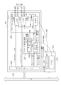
図2は、TOE101及び主記憶部103の構成を詳細に示すブロック図である。図2に示すように、TOE101は、プロトコル前後処理部201、プロトコル入出力処理部205及びホストインタフェース209により構成される。
FIG. 2 is a block diagram showing in detail the configuration of the
プロトコル前後処理部201において、202は、一時メモリ(第2の記録媒体)である。PCB(プロトコル制御ブロック)は、プロトコル処理を制御するための情報(プロトコル制御情報)で、実際には、INPCBとTCPCBとから成る。一時メモリ202内の203は、PCB記憶領域であり、PCBを複数組保持するためのメモリ上の領域である。PCB記憶領域203に保持されるPCBの組は、主記憶部103内のPCB記憶領域212に保持されるPCBの部分集合である。なお、一時メモリは、TOE101内の不図示のサブプロセッサによって高速アクセス可能なメモリである。また、INPCBは、Internet Protocol Control Blockの略称である。TCPCBは、TCP Protocol Control Blockの略称である。
In the protocol pre- and
204は、ソケット設定部である。206、207は、それぞれ出力部、入力部であり、ストリームメッセージ及び制御メッセージをMAC層と入出力する。
208は、制御部であり、PCB記憶領域203に格納されるPCBの内容に従ってプロトコル制御を行うとともに、PCB記憶領域203内のPCBを更新する。なお、制御部208は、本発明のプロトコル処理手段の一適用例となる構成である。
A
209は、ホストインタフェースであり、バス102に接続されるプロセッサ100(図1)との間の通信を制御する。
A
主記憶部103において、211は、ソケットテーブルであり、コネクション毎のソケット情報を保持する。212は、PCB記憶領域であり、一時メモリ202内のPCB記憶領域203に保持されるPCBの組を含む、その時点で存在するPCBの全ての組を保持している。
In the
なお、説明の簡単のため、図2には、図1のプロセッサ100、MAC/PHY104及びイーサネット(登録商標)105に相当する構成は図示されていない。
For the sake of simplicity, FIG. 2 does not show a configuration corresponding to the
図3は、図2の出力部206、プロトコル前後処理部201、入力部207及び制御部208の詳細な構成を示すブロック図である。
FIG. 3 is a block diagram illustrating detailed configurations of the
出力部206は、ソケット出力部2061、TCP出力部2062、UDP出力部2063、IP出力部2064及びMAC出力部2065から構成される。
The
ソケット出力部2061は、ユーザからのストリーム出力を適正な通信チャネルから出力するための機能を備える。
The
TCP出力部2062は、ユーザからのストリーム出力にTCPヘッダを付けて下層であるIP出力部2064にセグメントを出力する。
The
UDP出力部2063は、ユーザからのストリーム出力のソケットがUDPソケットである場合は、ストリームにUDPヘッダを付けて下層であるIP出力部2064にデータグラムを出力する。 When the stream output socket from the user is a UDP socket, the UDP output unit 2063 attaches a UDP header to the stream and outputs a datagram to the lower-level IP output unit 2064.
IP出力部2064は、トランスポート層(TCP出力部2062やUDP出力部2063)からのセグメントやデータグラムを受信してIPパケットとして構成し、IPヘッダを付加する。
The IP output unit 2064 receives segments and datagrams from the transport layer (
MAC出力部2065は、IP層からのIPパケットにMACヘッダを付加してインタフェースにフレーム出力する。 The MAC output unit 2065 adds a MAC header to the IP packet from the IP layer and outputs the frame to the interface.
入力部207は、ソケット入力部2071、TCP入力部2072、UDP入力部2073、IP入力部2074及びMAC入力部2075から構成される。
The
MAC入力部2075は、インタフェースから受けたフレームのMACヘッダの妥当性を検証し、MACヘッダを除去する。 The MAC input unit 2075 verifies the validity of the MAC header of the frame received from the interface, and removes the MAC header.
IP入力部2074は、MAC入力部2075から受けたIPパケットの妥当性を検証する。必要であれば、IP入力部2074は、IPフラグメントの再構成等を行い、IPパケットをトランスポート層より上位に解釈可能な形に整形し、IPヘッダを除去した上で適切なトランスポート(UDP又はTCP)層にそのIPパケットのペイロードを出力する。 The IP input unit 2074 verifies the validity of the IP packet received from the MAC input unit 2075. If necessary, the IP input unit 2074 performs reconfiguration of the IP fragment, etc., shapes the IP packet into a form that can be interpreted higher than the transport layer, removes the IP header, and performs an appropriate transport (UDP). (Or the TCP) layer outputs the payload of the IP packet.
UDP入力部2073は、IP入力部2074から受けたUDPデータグラムのヘッダの妥当性を検証し、UDPヘッダを除去し、ソケット入力部2071にデータグラムペイロードを出力する。
The UDP input unit 2073 verifies the validity of the header of the UDP datagram received from the IP input unit 2074, removes the UDP header, and outputs the datagram payload to the
TCP入力部2072は、IP入力部2074から受けたTCPセグメントのヘッダの妥当性を検証し、TCPヘッダを除去し、セグメントのペイロードをストリームとしてソケット入力部2071に出力する。
The TCP input unit 2072 verifies the validity of the header of the TCP segment received from the IP input unit 2074, removes the TCP header, and outputs the segment payload as a stream to the
ソケット入力部2071は、トランスポート層入力部(UDP入力部2073又はTCP入力部2072)から受けたストリーム又はデータグラムをその通信チャネル(ソケット)から判断して、適切なアプリケーション(ユーザデバイス)に出力する。
The
制御部208は、TCP制御部2081及びIP制御部2082により構成される。TCP制御部2081は、TCP入力部2072が検出したフラグセグメント受信、内部に持つタイマイベント、ソケット設定部204からのコネクション確立・消去指示を基に、ソケット毎のTCP状態制御等を行う。そして、TCP制御部2081は、TCP出力部2062にセグメント出力の指示を行う。
The
IP制御部2082は、IP入力部2074からのIPパケット受信イベントを基に、受信IPパケット受信可否判断依頼やIP出力部2064からのストリーム出力時のルーティング問い合わせ依頼の処理を行う。
Based on the IP packet reception event from the IP input unit 2074, the
プロトコル前後処理部201は、ソケット設定部204、TCPCB記憶領域203a及びINPCB記憶領域203bから構成される。
The
ソケット設定部204は、ユーザデバイスからのSA/DA設定やコネクション確立/消去指示を受信し、ソケットテーブル211の確保・更新・消去を行い、プロトコル入出力処理部205にコネクション確立・消去に伴うフレーム出力を依頼する。
The
ソケットテーブル211は、複数の通信チャネル(ソケット)各々に対し、そのSAAddr/DAAddr/SAPort/DAPort、通信パラメータ、扱うプロトコルとそのプロトコルに付随するPCBへの参照情報及びトランスポート層のプロトコル種別(UDP/TCP等)を保持する。なお、SAAddr/DAAddr/SAPort/DAPortは、SourceAddress/DestinationAddress/SroucePort/DestinationPortの略である。SAAddrは自局側IPアドレス、DAAddrは相手側IPアドレス、SAPortは自局側ポート番号、DAPortは相手側ポート番号である。 The socket table 211 includes, for each of a plurality of communication channels (sockets), SAAddr / DAAddr / SAPort / DAPort, communication parameters, protocol to be handled, reference information to the PCB accompanying the protocol, and protocol type (UDP) of the transport layer. / TCP etc.). SAAddr / DAAddr / SAPort / DAPort is an abbreviation for SourceAddress / DestinationAddress / SroucePort / DestinationPort. SAAddr is the local station IP address, DAAddr is the partner IP address, SAPort is the local port number, and DAPort is the partner port number.
厳密には、SAAddr/DAAddr/SAPort/DAPortは、INPCB記憶領域203bに保存される。この場合、ソケットテーブル211には、該当するソケットがどのINPCBレコードを参照すべきかを示す参照情報を保持することになる。
Strictly speaking, SAAddr / DAAddr / SAPort / DAPort is stored in the
TCPCB記憶領域203aは、TCPを制御する為に各通信チャネル(ソケット)毎にTCPコネクションの状態や必要なパラメータを保存する。
The
INPCB記憶領域203bは、IPを制御する為に各通信チャネル(ソケット)毎にSAAddr/DAAddr/SAPort/DAPortやTTL/TOSやオプション等を保存する。
The
なお、図2のPCB記憶領域203は、図3のTCPCB記憶領域203aとINPCB記憶領域203bとに相当する。
The PCB storage area 203 in FIG. 2 corresponds to the
以下、図2を用いて、プロトコル前後処理部201及びプロトコル入出力処理部205には図3に示した機能ブロックが含まれることを前提に、プロトコル前後処理部201とプロトコル入出力処理部205について説明する。
Hereinafter, with reference to FIG. 2, the protocol pre-processing and
プロセッサ100上で動作するユーザアプリケーションプログラムからTCPによるストリーム通信が要求されると、プロセッサ100上で動作するOSは、ストリーム入出力に前後し、コネクションDA及びコネクションSAの設定をTOE200に依頼する。
When stream communication by TCP is requested from a user application program running on the
TOE200では、この依頼をプロトコル前後処理部201において受信し、プロトコル前後処理部201の中でもその依頼はソケット設定部204により処理される。ソケット設定部204では、コネクションDA及びコネクションSAに関する設定はソケットテーブル211に保存すべきものと判断し、ソケットテーブル211にコネクションDA及びコネクションSAに関する設定を行う。このとき、このコネクションに対応するPCBが主記憶部103内のPCB記憶領域212に新たに生成され、初期化が行われる。
In the TOE 200, this request is received by the
(1)次に、ユーザアプリケーションは、コネクションの確立指示を行う。TOE200では、この指示についてもプロトコル前後処理部201にてソケット設定部204が受信し、処理を判断する。この際、ソケット設定部204は、主記憶部210内のPCB記憶領域212から該当するPCBを一時メモリ202内のPCB記憶領域203にコピーする。このとき、PCB記憶領域203に空き領域がない場合は、PCB記憶領域203から最も使われる可能性の低い(例えば、最も長い間使われていない)PCBを一つ選択し、前述のコピーに先んじてPCB記憶領域212に書き戻す。
(1) Next, the user application issues a connection establishment instruction. In the TOE 200, this instruction is received by the
ソケット設定部204は、コネクション確立指示に起因する制御フレームの送信指示をプロトコル入出力処理部205に対して行う。プロトコル入出力処理部205において、このコネクション確立指示は、制御部208により処理される。
The
制御部208では、コネクション確立においてどの様な制御フレームを送信すべきか判断し、また、その制御フレームを送信することによりプロトコル状態がどのように変化するかを判断し、これをPCB記憶領域203にパラメータとして設定する。この行為は、具体的にはTCPであればSYNセグメントの送信判断とSYNセグメントを送信した場合の状態遷移による状態変数の変更をTCPCB記憶領域203aに設定する行為に該当する。この制御部208の状態変数変更の機能構成が、本発明の更新手段の一適用例となる構成である。
The
制御部208では、コネクション確立に伴う制御フレーム送信の判断とソケットテーブル211及びPCB記憶領域212、203の設定は行うが、実際のフレーム送信作業は出力部206によって行われる。
The
制御部208は、制御フレームを送信する必要性を判断すれば、制御メッセージ出力要求を出力部206に送信する。出力部206では、(他の)ストリーム送信の合間をみて、これらの例えばコネクション確立時に必要な制御フレーム送信を行う。
When the
(2)ユーザアプリケーション又はOSカーネルは、SA/DA設定とコネクション確立指示とが終了すれば、ストリームを出力することができる。ストリーム出力指示は、TOE200の中でもプロトコル入出力処理部205内の出力部206が直接受け取る。出力部206内部でも、ストリーム出力指示は、ソケット出力部2061、TCP出力部2062又はUDP出力部2063、IP出力部2064及びMAC出力部2065にて処理される。この際、必要ならばPCB記憶領域203を参照しながら、実際のフレームが作成され、出力される。
(2) The user application or the OS kernel can output a stream when the SA / DA setting and the connection establishment instruction are completed. The stream output instruction is directly received by the
この場合、まず、制御部208がソケットテーブル211を参照した結果、必要なPCBが判明する。次に、制御部208は、PCB記憶領域203を参照し、該当するPCBが存在するかどうかを調べる。もし存在しない場合は、制御部208は、主記憶部210内のPCB記憶領域212から該当するPCBをPCB記憶領域203にコピーする。このとき、PCB記憶領域203に空き領域がない場合は、PCB記憶領域203から最も使われる可能性の低い(例えば、最も長い間使われていない)PCBを一つ選択し、前述のコピーに先んじてPCB記憶領域212に書き戻す。
In this case, first, as a result of the
(3)MAC層からストリームフレームを受信した場合は、入力部207がこれを受ける。入力部207内では、MAC入力部2075、IP入力部2074、UDP入力部2073又はTCP入力部2072及びソケット入力部2071にてその受信ストリームフレームを処理し、OSカーネル又はユーザアプリケーションにストリーム入力を行う。この際、特にそのストリームがどの通信チャネル(ソケット)に属するものであるかを判断するために、ソケットテーブル211及びPCB記憶領域203を参照する必要がある。
(3) When a stream frame is received from the MAC layer, the
まず、制御部208がソケットテーブル211を参照した結果、必要なPCBが判明する。次に、PCB記憶領域203を参照し、該当するPCBが存在するかどうかを調べる。もし存在しない場合は、PCB記憶領域212から該当するPCBをPCB記憶領域203にコピーする。このとき、PCB記憶領域203に空き領域がない場合は、PCB記憶領域203から最も使われる可能性の低い(例えば、最も長い間使われていない)PCBを一つ選択し、前述のコピーに先んじてPCB記憶領域212に書き戻す。
First, as a result of the
ストリーム入出力中には、プロトコル制御のためのフレームをMAC層から受信する可能性があるが、これは、入力部207ではそのヘッダ解析を行う程度にとどめ、プロトコル制御の為の実際の処理は制御部208にて行う。このため、入力部207はプロトコル制御関連フレームを受信すると、制御部208に対して制御メッセージを受信した旨とその種別と解析の結果得られた必要なデータを送信する。制御部208では、この制御メッセージ受信のイベントをトリガにPCB記憶領域203を操作した上で、再び出力部206に対してプロトコル制御の為の制御メッセージ出力を依頼する場合もある。
During stream input / output, there is a possibility that a frame for protocol control may be received from the MAC layer. However, this is limited to the header analysis at the
ユーザアプリケーションによるストリーム入出力が終了すれば、ユーザアプリケーションは、コネクション消去指示を行うがその基本的な処理の流れはコネクション確立指示と同じである。 When stream input / output by the user application is completed, the user application issues a connection erasure instruction, but the basic processing flow is the same as the connection establishment instruction.
上述したように、(1)コネクション確立、(2)ストリーム出力及び(3)ストリーム入力のケースでは、PCB記憶領域203に保持されるPCBの一組とPCB記憶領域203に保持されるPCBの一組との間で入れ替えが生じることがある。このとき、PCB記憶領域203に保持されるPCBの一組をまず主記憶部210に書き戻す必要がある。本実施形態においては、毎回全てのPCBを書き戻すことはなく、変更された部分だけを書き戻すようにしている。 As described above, in the case of (1) connection establishment, (2) stream output, and (3) stream input, one set of PCB held in the PCB storage area 203 and one set of PCB held in the PCB storage area 203 Swaps may occur between pairs. At this time, it is necessary to first write back a set of PCBs held in the PCB storage area 203 to the main storage unit 210. In the present embodiment, all PCBs are not written back every time, but only the changed portions are written back.
具体的には、INPCB記憶領域203bに格納されるデータ(INPCB)を例に挙げると、相手側IPアドレス、相手側ポート番号、自局側IPアドレス、自局側ポート番号を含むが、これらは一つのコネクションに不変の値であるので書き戻すことはない。一方、INPCBには、これ以外にIPオプション、フラグ等、通信中に変更される可能性のあるパラメータも含み、これらは書き戻しの対象になる。
Specifically, taking the data (INPCB) stored in the
TCPCB記憶領域203aに格納されるデータ(TCPCB)ついては、大きくは送信パラメータ、受信パラメータに分けられる。図4にTCPCBの抜粋を示す。図4で接頭辞snd_から始まるパラメータは送信パラメータ、rcv_から始まるパラメータは受信パラメータである。TCPCBも実装に依存し、コネクション毎に不変のパラメータと可変のパラメータに分離することができる。例えば、図4において、リアセンブルキューへのポインタt_segqは不変であるように実装することが可能である。
Data (TCPCB) stored in the
上述のように、PCB内の各パラメータは、コネクション毎に不変のパラメータと通信中に更新されるパラメータとに区分される。 As described above, each parameter in the PCB is classified into a parameter that does not change for each connection and a parameter that is updated during communication.
本実施形態においては、PCBを上述のように区分して管理する。図5は、一時メモリ202内のPCB記憶領域203におけるPCBの格納状態を模式的に示す図である。 In the present embodiment, the PCB is divided and managed as described above. FIG. 5 is a diagram schematically showing a PCB storage state in the PCB storage area 203 in the temporary memory 202.
図5に示すように、PCB記憶領域203には、各コネクションに対応するPCBが格納されており、各PCBは、TCPプロトコル処理中において不変のパラメータ部分(不変部)と変更されるパラメータ部分(変数部)とに区別される。なお、一PCBあたり256Byte、後述するパラメータ更新情報がMbitであるため、PCB記憶領域203には、一時メモリ容量/(256Byte+Mbit)の数のPCBが格納可能である。 As shown in FIG. 5, the PCB storage area 203 stores a PCB corresponding to each connection, and each PCB has an invariable parameter part (an invariant part) and a parameter part (a constant part) that is changed during TCP protocol processing ( Variable part). Since the parameter update information to be described later is Mbit with 256 bytes per PCB, the PCB storage area 203 can store the number of temporary memory capacity / (256 bytes + Mbit) PCBs.
また、図5においては、PCBのうちの一つについて、コネクション毎に不変なパラメータ、主記憶部103への書き戻し時まで変更のなかったパラメータ、及び、主記憶部103への書き戻し時に変更されたパラメータを区別して表している。これは、説明の便宜のためであり、図5に示す全PCBについて上記3種のパラメータが存在し得る。
In FIG. 5, for one of the PCBs, a parameter that does not change for each connection, a parameter that has not been changed until writing back to the
ここで、各PCBには、パラメータ更新情報が付加されている。任意の一組のPCBがPCB記憶領域212からPCB記憶領域203にコピーされるとき、当該PCBのパラメータ更新情報はクリアされた状態にある。その後、ソケット設定部204又は制御部208がPCB記憶領域203内に保持される任意のPCBを更新した際、当該PCBのパラメータ更新情報に更新情報ビットがセットされる。この更新情報ビットは、PCBの各パラメータ毎にセットできる値であり、更新情報ビットによって、どのパラメータが更新されたのかを示すことができる。その後、上述の(1)、(2)、(3)の何れかの事象が生じ、当該PCBがPCB記憶領域212に書き戻される場合には、当該PCBの更新情報ビットが参照され、実際に更新されたパラメータのみが選択され、書き戻される。この機能構成が、本発明の選択手段及び制御手段の一適用例となる構成である。
Here, parameter update information is added to each PCB. When an arbitrary set of PCBs is copied from the
以上のようにして、本実施形態においては、変更された部分だけを一時メモリ203から主記憶部103に書き戻すようにしている。従って、一時メモリ202に格納されるPCBと主記憶部103に格納されるPCBとを入れ替える際の書き込みデータ量を削減でき、一時メモリ入れ替えに要する時間を短縮することが可能となる。その結果、プロトコル処理性能を向上させることができる。
As described above, in this embodiment, only the changed part is written back from the temporary memory 203 to the
また、主記憶部103への書き込みに要するバス、メモリ帯域を低減でき、その分をシステム内の他の装置に振り分けることができるため、システム全体の処理性能を向上させるとともに、システムの消費電力を低減することが可能となる。
In addition, since the bus and memory bandwidth required for writing to the
本発明の一適用例として上述した実施形態を説明したが、本発明の要旨を逸脱しない範囲で様々な変更が可能であることはいうまでもない。 Although the above-described embodiment has been described as an application example of the present invention, it goes without saying that various modifications can be made without departing from the gist of the present invention.
例えば、上述した実施形態においては、PCBの各パラメータ毎に更新情報ビットを設ける例を示したが、これに限定するものではない。例えばパラメータをバス転送サイズ、主記憶アクセスサイズに適合するようにいくつかをグルーピングし、各グループ毎に更新情報ビットを設けて管理しても良い。その際には、変更される可能性の高いパラメータを選択的にグループ化するよう構成すれば、より高い効果が得られることは言うまでもない。 For example, in the above-described embodiment, an example in which update information bits are provided for each parameter of the PCB has been described, but the present invention is not limited to this. For example, some parameters may be grouped so as to conform to the bus transfer size and main memory access size, and an update information bit may be provided for each group for management. In that case, it goes without saying that a higher effect can be obtained by selectively grouping parameters that are likely to be changed.
<第2の実施形態>
次に、本発明の第2の実施形態について説明する。なお、本実施形態に係るプロトコル処理装置の構成は、図1乃至図3に示す構成と同様であるため、その説明は省略する。また、本実施形態に係るプロトコル処理装置は、上述した第1の実施形態に係るプロトコル処理装置の機能を備えているものとする。
<Second Embodiment>
Next, a second embodiment of the present invention will be described. Note that the configuration of the protocol processing apparatus according to the present embodiment is the same as the configuration shown in FIGS. The protocol processing device according to the present embodiment is assumed to have the function of the protocol processing device according to the first embodiment described above.
一時メモリ202内のPCB記憶領域203に保持されるPCB及び主記憶部210内のPCB記憶領域212に保持されるPCBは、図6に示すように、リオーダリング情報が追加された構成となっている。即ち、本実施形態におけるPCBは、相手側IPアドレス、相手側ポート番号、自局側IPアドレス、自局側ポート番号等の従来のPCBのパラメータの他、リオーダリング情報も含まれる。
The PCB held in the PCB storage area 203 in the temporary memory 202 and the PCB held in the
TCPプロトコル処理においては、上述したパラメータの他、リオーダリング情報もアクセスの対象となる。リオーダリングとは、TCPプロトコル処理において、順不同で受信したパケットを送信ストリームの順番に並び替える処理である。 In the TCP protocol processing, in addition to the parameters described above, reordering information is also an access target. Reordering is a process of rearranging packets received out of order in the order of the transmission stream in the TCP protocol process.
TCPプロトコル処理において、送信元から送信されたパケットは、各々が異なる経路を通過して送信先に到着する可能性がある。経路毎にネットワークの状況は異なるため、パケットが送信されてから受信されるまでにかかる時間が大きくなることがあり、パケットは送信元から送信された順番で送信先に到着することがある。よって、送信先では、受信したパケットを送信元が送信した順番に並び替える必要がある。その際、リオーダリング情報は、送信先が受信したパケットを並び替えるために利用される情報であり、受信したパケットが不連続になる箇所をポインタ等で管理するものである。 In the TCP protocol processing, packets transmitted from the transmission source may arrive at the transmission destination through different paths. Since the network conditions are different for each route, the time it takes for the packet to be received after it is transmitted may increase, and the packet may arrive at the destination in the order of transmission from the source. Therefore, it is necessary for the transmission destination to rearrange the received packets in the order of transmission from the transmission source. At this time, the reordering information is information used for rearranging the packets received by the transmission destination, and manages the location where the received packets are discontinuous with a pointer or the like.
また、リオーダリング情報は、0個以上、予め定められた個数以下の不連続情報で構成される。本実施形態においては、PCB記憶領域203の容量の制約上、各PCBについて4つまでの不連続情報を保持することを許容している。不連続情報は、TCP入力部2072が受信したパケットが不連続になる位置(不連続開始点)と、その位置から次に受信したパケットの先頭の位置までのサイズ(不連続サイズ)とで構成される。なお、ここでいう位置とは、例えば、受信データを一時的に格納するTCP入力部2072内のバッファメモリの格納位置のことをいう。 Further, the reordering information is composed of zero or more pieces of discontinuous information of a predetermined number or less. In the present embodiment, due to the capacity limitation of the PCB storage area 203, it is allowed to hold up to four pieces of discontinuous information for each PCB. The discontinuity information is composed of a position at which a packet received by the TCP input unit 2072 becomes discontinuous (discontinuity start point) and a size (discontinuous size) from that position to the top position of the next packet received. Is done. Note that the position here means, for example, the storage position of the buffer memory in the TCP input unit 2072 that temporarily stores received data.
入力部207内のTCP入力部2072は、不連続なデータを受信した場合に、PCB記憶領域203内に保持されるPCBのリオーダリング情報に不連続情報を登録する。このTCP入力部2072の機能構成が、本発明の受信手段及び登録手段の一適用例となる構成である。
When receiving discontinuous data, the TCP input unit 2072 in the
TCP入力部2072が受信したデータは、送信元から送信された順番でソケット入力部2071へ一定の単位で転送される。即ち、TCP入力部2072は、受信したパケットのシーケンス番号(送信元の送信順番を示す情報)に従って、送信元から送信された順番となるようにパケットの転送順番を入れ換えて、ソケット入力部2071に転送する。このTCP入力部2072の機能構成が、本発明の並び替え手段の一適用例となる構成である。
Data received by the TCP input unit 2072 is transferred to the
例えば、図7(a)に示すように、既にパケットa、パケットcを受信した状態で新たにパケットbを受信した場合、パケットa〜cのシーケンス番号からパケットbをどの位置に挿入して転送するのかを判定する。図7(a)に示す例は、シーケンス番号により示される送信元の送信順番が、パケットa、パケットb、パケットcの順番であることを前提としている。従って、TCP入力部2072は、パケットaとパケットcとの間にパケットbを挿入して転送することになる。このとき、不連続情報(不連続開始点1、不連続サイズ1)が参照されることによって、パケットaとパケットcとの間の位置にパケットbが挿入される。また、図7(a)の例においては、パケットaとパケットcとの間にパケットbを挿入することによって、パケットa〜パケットcを連続的に転送できるようになっている。この場合、不連続情報(不連続開始点1、不連続サイズ1)は不要となるため、TCP入力部2072によって削除される。このTCP入力部2072の機能構成が、本発明の第1の削除手段の一適用例となる構成である。
For example, as shown in FIG. 7A, when a packet b is newly received in a state where packets a and c have already been received, the packet b is inserted and transferred from the sequence number of the packets a to c. Determine whether to do. The example illustrated in FIG. 7A is based on the premise that the transmission order of the transmission source indicated by the sequence number is the order of packet a, packet b, and packet c. Accordingly, the TCP input unit 2072 inserts and transfers the packet b between the packet a and the packet c. At this time, by referring to the discontinuity information (
また、図7(b)に示すように、TCP入力部2072は、既にパケットa〜d、パケットfを受信した状態で新たにパケットeを受信した場合、パケットa〜fのシーケンス番号からパケットeをどの位置に挿入して転送するのかを判定する。 Also, as shown in FIG. 7B, when the TCP input unit 2072 has newly received the packet e in a state where the packets a to d and the packet f have been received, the TCP input unit 2072 starts from the sequence number of the packets a to f. To which position is inserted and transferred.
図7(b)に示す例は、シーケンス番号により示される送信元の送信順番が、パケットa、パケットb、パケットc、パケットd、パケットe、パケットfの順番であることを前提としている。従って、TCP入力部2072は、パケットdとパケットfとの間にパケットeを挿入して転送することになる。 The example illustrated in FIG. 7B is based on the assumption that the transmission order of the transmission source indicated by the sequence number is the order of packet a, packet b, packet c, packet d, packet e, and packet f. Accordingly, the TCP input unit 2072 inserts and transfers the packet e between the packet d and the packet f.
但し、本実施形態においては、PCB記憶領域203のメモリ容量の制約から一つのPCBに対して4つまでの不連続情報しか設定することができない。よって、TCP入力部2072は、上記パケットの並び替えの結果、5つの不連続情報に対応するパケットのうち、時間的に最も後方に位置するパケットの不連続開始点を示す不連続情報を選択する。即ち、ここでは、送信元から最後に送信されたパケットに対応する不連続情報を選択している。 However, in the present embodiment, up to four pieces of discontinuous information can be set for one PCB due to the memory capacity limitation of the PCB storage area 203. Therefore, the TCP input unit 2072 selects the discontinuity information indicating the discontinuity start point of the packet positioned backward most in time among the packets corresponding to the five discontinuity information as a result of the rearrangement of the packets. . That is, here, discontinuous information corresponding to the packet transmitted last from the transmission source is selected.
そして、TCP入力部2072は、リオーダリング情報から選択された不連続情報を削除する。また、削除される不連続情報が示す不連続開始点の後に存在するパケットfも削除する。このTCP入力部2072の機能構成が、本発明の第2の削除手段の一適用例となる構成である。 Then, the TCP input unit 2072 deletes the discontinuous information selected from the reordering information. Further, the packet f existing after the discontinuity start point indicated by the discontinuity information to be deleted is also deleted. The functional configuration of the TCP input unit 2072 is a configuration serving as an application example of the second deletion unit of the present invention.
以上のようにして、本実施形態においては、PCBにリオーダリング情報を含むことで、一時メモリ202の容量制限に基づく制約を守りつつ、TOE101(TCP入力部2072)によるリオーダリング情報へのアクセスの高速化を図ることが可能となる。これにより、TCP受信処理における受信データの並べ替え処理時間が短縮され、その結果、プロトコルスタック処理の高速化が可能になる。 As described above, in the present embodiment, by including the reordering information in the PCB, it is possible to access the reordering information by the TOE 101 (TCP input unit 2072) while keeping the restrictions based on the capacity limitation of the temporary memory 202. It is possible to increase the speed. As a result, the time required for rearranging the received data in the TCP reception process is shortened, and as a result, the protocol stack process can be speeded up.
また、本実施形態によれば、リオーダリング情報をPCBと独立して管理する必要がないため、リオーダリング情報を管理するための専用機構を設ける必要がなく、実装規模を縮小させることができる。 Further, according to the present embodiment, since it is not necessary to manage the reordering information independently from the PCB, it is not necessary to provide a dedicated mechanism for managing the reordering information, and the mounting scale can be reduced.
本発明の一適用例として上述した実施形態を説明したが、本発明の要旨を逸脱しない範囲で様々な変更が可能であることはいうまでもない。 Although the above-described embodiment has been described as an application example of the present invention, it goes without saying that various modifications can be made without departing from the gist of the present invention.
例えば、上述した実施形態においては、リオーダリング情報が持つ不連続情報の最大数を4としているが、これに限定するものではない。不連続情報の最大数は、一時メモリ202の容量とコストから決定されてもよい。また、本実施形態においては、不連続情報の数が予め決められた数より大きくなる場合に、その数を超える不連続情報と対応する受信データとを削除している。この他にも、データ先頭から最も離れている不連続開始点を示す不連続情報を選択した後、選択された不連続情報を主記憶部103等、他の記録媒体に保持する実施形態も考えられる。この機能構成が、本発明の退避手段の一適用例となる構成である。
For example, in the above-described embodiment, the maximum number of discontinuous information included in the reordering information is 4, but the present invention is not limited to this. The maximum number of discontinuous information may be determined from the capacity and cost of the temporary memory 202. Further, in the present embodiment, when the number of discontinuous information is larger than a predetermined number, discontinuous information exceeding the number and received data corresponding to the discontinuous information are deleted. In addition to this, an embodiment in which the discontinuous information indicating the discontinuous start point farthest from the data head is selected and then the selected discontinuous information is held in another recording medium such as the
また、本発明の目的は、前述した実施形態の機能を実現するソフトウェアのプログラムコードを記録した記憶媒体をシステム或いは装置に供給し、そのシステム等のコンピュータが記憶媒体からプログラムコードを読み出し実行することによっても達成される。 Another object of the present invention is to supply a storage medium storing software program codes for realizing the functions of the above-described embodiments to a system or apparatus, and a computer such as the system reads and executes the program codes from the storage medium. Is also achieved.
この場合、記憶媒体から読み出されたプログラムコード自体が前述した実施形態の機能を実現することになり、プログラムコード自体及びそのプログラムコードを記憶した記憶媒体は本発明を構成することになる。 In this case, the program code itself read from the storage medium realizes the functions of the above-described embodiments, and the program code itself and the storage medium storing the program code constitute the present invention.
プログラムコードを供給するための記憶媒体としては、例えば、フレキシブルディスク、ハードディスク、光ディスク、光磁気ディスク、CD−ROM、CD−R、磁気テープ、不揮発性のメモリカード、ROM等を用いることができる。 As a storage medium for supplying the program code, for example, a flexible disk, a hard disk, an optical disk, a magneto-optical disk, a CD-ROM, a CD-R, a magnetic tape, a nonvolatile memory card, a ROM, or the like can be used.
また、コンピュータが読み出したプログラムコードの指示に基づき、コンピュータ上で稼動しているOS等が実際の処理の一部又は全部を行い、その処理によって前述した実施形態の機能が実現される場合も含まれる。 In addition, the case where the functions of the above-described embodiment are realized by performing part or all of the actual processing by an OS or the like running on the computer based on the instruction of the program code read by the computer. It is.
さらに、記憶媒体から読み出されたプログラムコードが、コンピュータに接続された機能拡張ユニット等に備わるメモリに書込まれた後、そのプログラムコードの指示に基づきCPU等が実際の処理を行い、前述した実施形態の機能が実現される場合も含まれる。 Further, after the program code read from the storage medium is written in a memory provided in a function expansion unit connected to the computer, the CPU or the like performs actual processing based on the instruction of the program code, and the above-described processing is performed. The case where the functions of the embodiment are realized is also included.
10 プロトコル処理装置
100 プロセッサ
101 TOE
102 バス
103 主記憶部
104 MAC/PHY
105 イーサネット(登録商標)
201 プロトコル前後処理部
202 一時メモリ
203、212 PCB記憶領域
204 ソケット設定部
205 プロトコル入出力部
206 出力部
207 入力部
208 制御部
209 ホストインタフェース
211 ソケットテーブル
2061 ソケット出力部
2062 TCP出力部
2063 UDP出力部
2064 IP出力部
2065 MAC出力部
2071 ソケット入力部
2072 TCP入力部
2073 UDP入力部
2074 IP入力部
2075 MAC入力部
2081 TCP制御部
2082 IP制御部
10
102
105 Ethernet (registered trademark)
201 Protocol Pre- and Post-Processing Unit 202
Claims (9)
第1の記録手段と、
第2の記録手段と、
コネクションの処理を含むプロトコル処理を行うプロトコル処理手段と、を有し、
前記プロトコル処理手段は、コネクション毎に設定される制御情報を、前記第2の記録手段から前記第1の記録手段に転送し、コネクションの処理に応じて、前記第1の記録手段に記録された制御情報の一部分を更新し、前記第1の記録手段において更新された制御情報の前記一部分を選択し、選択された制御情報の前記一部分を、前記第1の記録手段から前記第2の記録手段に書き戻すことを特徴とする通信装置。 A communication device,
First recording means;
A second recording means;
Protocol processing means for performing protocol processing including connection processing;
The protocol processing means transfers control information set for each connection from the second recording means to the first recording means, and is recorded in the first recording means in accordance with the connection processing. update the portion of the control information, said first selecting the portion of the updated control information in the recording means, the portion of the selected control information, wherein the first recording means second recording means A communication device characterized by writing back to
Priority Applications (2)
| Application Number | Priority Date | Filing Date | Title |
|---|---|---|---|
| JP2006334787A JP4921142B2 (en) | 2006-12-12 | 2006-12-12 | Communication device |
| US11/952,217 US7720979B2 (en) | 2006-12-12 | 2007-12-07 | Communication apparatus |
Applications Claiming Priority (1)
| Application Number | Priority Date | Filing Date | Title |
|---|---|---|---|
| JP2006334787A JP4921142B2 (en) | 2006-12-12 | 2006-12-12 | Communication device |
Publications (3)
| Publication Number | Publication Date |
|---|---|
| JP2008148133A JP2008148133A (en) | 2008-06-26 |
| JP2008148133A5 JP2008148133A5 (en) | 2010-02-04 |
| JP4921142B2 true JP4921142B2 (en) | 2012-04-25 |
Family
ID=39499719
Family Applications (1)
| Application Number | Title | Priority Date | Filing Date |
|---|---|---|---|
| JP2006334787A Expired - Fee Related JP4921142B2 (en) | 2006-12-12 | 2006-12-12 | Communication device |
Country Status (2)
| Country | Link |
|---|---|
| US (1) | US7720979B2 (en) |
| JP (1) | JP4921142B2 (en) |
Families Citing this family (6)
| Publication number | Priority date | Publication date | Assignee | Title |
|---|---|---|---|---|
| JP5353278B2 (en) | 2009-02-06 | 2013-11-27 | 富士通株式会社 | Communication device |
| JP2010278897A (en) * | 2009-05-29 | 2010-12-09 | Renesas Electronics Corp | Communication data processing circuit and communication data processing method |
| JP5568164B2 (en) * | 2013-05-27 | 2014-08-06 | 株式会社東芝 | Communication apparatus and program thereof |
| JP6351363B2 (en) * | 2013-08-01 | 2018-07-04 | キヤノン株式会社 | Communication apparatus and data processing method thereof |
| US20200050913A1 (en) * | 2017-04-19 | 2020-02-13 | Sensormatic Electronics, LLC | Systems and methods for providing a security tag with synchronized display |
| CN110958213B (en) | 2018-09-27 | 2021-10-22 | 华为技术有限公司 | Method for processing TCP message, TOE component and network equipment |
Family Cites Families (13)
| Publication number | Priority date | Publication date | Assignee | Title |
|---|---|---|---|---|
| US4908823A (en) * | 1988-01-29 | 1990-03-13 | Hewlett-Packard Company | Hybrid communications link adapter incorporating input/output and data communications technology |
| US5537417A (en) * | 1993-01-29 | 1996-07-16 | International Business Machines Corporation | Kernel socket structure for concurrent multiple protocol access |
| US6389479B1 (en) | 1997-10-14 | 2002-05-14 | Alacritech, Inc. | Intelligent network interface device and system for accelerated communication |
| JPH11313126A (en) | 1998-04-28 | 1999-11-09 | Matsushita Electric Ind Co Ltd | Communication control data processor and processing method |
| JP2001333075A (en) * | 2000-05-23 | 2001-11-30 | Canon Inc | Node unit, network and network control method |
| JP4068798B2 (en) * | 2000-10-31 | 2008-03-26 | 株式会社日立製作所 | Storage subsystem, I / O interface control method, and information processing system |
| US7734812B2 (en) * | 2002-06-06 | 2010-06-08 | International Business Machines Corporation | Method and apparatus for processing outgoing internet protocol packets |
| JP4429703B2 (en) * | 2003-11-28 | 2010-03-10 | 株式会社日立製作所 | Disk array device and disk array device control method |
| JP2006072440A (en) * | 2004-08-31 | 2006-03-16 | Hitachi Ltd | Storage device and data transfer method |
| JP4956922B2 (en) * | 2004-10-27 | 2012-06-20 | ソニー株式会社 | Storage device |
| JP2006256105A (en) * | 2005-03-17 | 2006-09-28 | Seiko Epson Corp | Printing device and data processing method |
| JP2006276973A (en) * | 2005-03-28 | 2006-10-12 | Nec Corp | Arithmetic device |
| JP4501159B2 (en) * | 2005-03-30 | 2010-07-14 | 株式会社デンソー | Automotive control unit |
-
2006
- 2006-12-12 JP JP2006334787A patent/JP4921142B2/en not_active Expired - Fee Related
-
2007
- 2007-12-07 US US11/952,217 patent/US7720979B2/en active Active
Also Published As
| Publication number | Publication date |
|---|---|
| US20080141009A1 (en) | 2008-06-12 |
| US7720979B2 (en) | 2010-05-18 |
| JP2008148133A (en) | 2008-06-26 |
Similar Documents
| Publication | Publication Date | Title |
|---|---|---|
| JP5470828B2 (en) | COMMUNICATION DEVICE FOR DATA DISTRIBUTION AND DATA DISTRIBUTION SYSTEM | |
| JP4638658B2 (en) | Method for uploading state object of offloaded network stack and method for synchronizing it | |
| US9071529B2 (en) | Method and apparatus for accelerating forwarding in software-defined networks | |
| US7239635B2 (en) | Method and apparatus for implementing alterations on multiple concurrent frames | |
| JP4504977B2 (en) | Data processing for TCP connection using offload unit | |
| JP4921142B2 (en) | Communication device | |
| JP5022691B2 (en) | COMMUNICATION DEVICE, ITS CONTROL METHOD, AND PROGRAM | |
| US10237130B2 (en) | Method for processing VxLAN data units | |
| KR100798926B1 (en) | Apparatus and method for forwarding packet in packet switch system | |
| US9304939B2 (en) | Method and multi-core communication processor for replacing data in system cache | |
| JP2009093348A (en) | Information processing apparatus and information processing system | |
| US20060221824A1 (en) | Storage system and data processing method | |
| JP5094482B2 (en) | Processing apparatus and processing method thereof | |
| US20110032952A1 (en) | Two stage internet protocol header compression | |
| US11546261B2 (en) | Congestion control method and related device | |
| JP2007129452A (en) | Communication apparatus and communication method | |
| CN112398754B (en) | Data transmission method, device, medium, electronic equipment and network access equipment | |
| CN102045234B (en) | Buffering and overtime processing methods of route address mapping information as well as tunnel router | |
| JP4040045B2 (en) | Data transfer device | |
| JP2009284028A (en) | Receiving apparatus and receiving method, communication system and communication method, transmission apparatus and transmission method, program, and recording medium | |
| JP5300355B2 (en) | Network protocol processing apparatus and processing method thereof | |
| KR100670817B1 (en) | Method and apparatus for implementation ipsec engine in ixdp2851 | |
| JP2017163346A (en) | Communication device, method and program | |
| JP4443266B2 (en) | Packet update device | |
| JP2006032995A (en) | Communication support apparatus |
Legal Events
| Date | Code | Title | Description |
|---|---|---|---|
| A521 | Request for written amendment filed |
Free format text: JAPANESE INTERMEDIATE CODE: A523 Effective date: 20091210 |
|
| A621 | Written request for application examination |
Free format text: JAPANESE INTERMEDIATE CODE: A621 Effective date: 20091210 |
|
| A977 | Report on retrieval |
Free format text: JAPANESE INTERMEDIATE CODE: A971007 Effective date: 20110215 |
|
| A131 | Notification of reasons for refusal |
Free format text: JAPANESE INTERMEDIATE CODE: A131 Effective date: 20110405 |
|
| A521 | Request for written amendment filed |
Free format text: JAPANESE INTERMEDIATE CODE: A523 Effective date: 20110603 |
|
| TRDD | Decision of grant or rejection written | ||
| A01 | Written decision to grant a patent or to grant a registration (utility model) |
Free format text: JAPANESE INTERMEDIATE CODE: A01 Effective date: 20120131 |
|
| A01 | Written decision to grant a patent or to grant a registration (utility model) |
Free format text: JAPANESE INTERMEDIATE CODE: A01 |
|
| A61 | First payment of annual fees (during grant procedure) |
Free format text: JAPANESE INTERMEDIATE CODE: A61 Effective date: 20120202 |
|
| R151 | Written notification of patent or utility model registration |
Ref document number: 4921142 Country of ref document: JP Free format text: JAPANESE INTERMEDIATE CODE: R151 |
|
| FPAY | Renewal fee payment (event date is renewal date of database) |
Free format text: PAYMENT UNTIL: 20150210 Year of fee payment: 3 |
|
| LAPS | Cancellation because of no payment of annual fees |