JP4920987B2 - Image forming apparatus - Google Patents
Image forming apparatus Download PDFInfo
- Publication number
- JP4920987B2 JP4920987B2 JP2006030219A JP2006030219A JP4920987B2 JP 4920987 B2 JP4920987 B2 JP 4920987B2 JP 2006030219 A JP2006030219 A JP 2006030219A JP 2006030219 A JP2006030219 A JP 2006030219A JP 4920987 B2 JP4920987 B2 JP 4920987B2
- Authority
- JP
- Japan
- Prior art keywords
- speed
- image forming
- forming apparatus
- conveying
- recording material
- Prior art date
- Legal status (The legal status is an assumption and is not a legal conclusion. Google has not performed a legal analysis and makes no representation as to the accuracy of the status listed.)
- Expired - Fee Related
Links
Images


Description
本発明は、画像形成装置に関し、より詳細には、定着装置を備える画像形成装置に関する。 The present invention relates to an image forming equipment, and more particularly relates to an image forming equipment comprising a fixing device.
従来、定着装置を備えた電子写真方式の画像形成装置において、トナー像を記録紙等のシート上に転写する転写部での搬送速度が変動し画像に影響を与えることがある。これは、転写部でのシート搬送速度と、シートにトナー像を定着する定着装置でのシート搬送速度とが微妙に異なることから、転写部と定着装置との間でシートの引っ張り合いが生じるためである。特に、プリント中の定着装置はシートへのトナー像の定着のために加熱されており、定着装置内の加圧ローラはその熱により膨張するため、定着装置でのシート搬送速度は徐々に速くなる傾向がある。これにより転写部と定着装置との搬送速度の速度差が徐々に大きくなり、シートが引っ張られて転写ずれなど画像に悪影響を及ぼすこととなる。 2. Description of the Related Art Conventionally, in an electrophotographic image forming apparatus provided with a fixing device, the conveyance speed at a transfer unit that transfers a toner image onto a sheet such as recording paper may fluctuate and affect the image. This is because the sheet conveyance speed at the transfer portion and the sheet conveyance speed at the fixing device that fixes the toner image on the sheet are slightly different, and the sheet is pulled between the transfer portion and the fixing device. It is. In particular, the fixing device during printing is heated for fixing the toner image on the sheet, and the pressure roller in the fixing device expands due to the heat, so that the sheet conveyance speed in the fixing device gradually increases. Tend. As a result, the difference in the conveyance speed between the transfer unit and the fixing device gradually increases, and the sheet is pulled to adversely affect the image such as transfer deviation.
そこで、搬送路上の定着装置の手前にシートのたわみ状態(ループ状態)を検知するセンサ(ループセンサと呼ぶ)を設けたものが提案されている(例えば、特許文献1参照)。このような装置では、検知したシートのループ状態に基づいて定着装置の搬送速度を制御(ループ制御という)し、転写部と定着装置との速度差を極力なくすようにしている。すなわち、定着装置の搬送速度は転写部の搬送速度に対して速い速度と遅い速度の2種類の速度を設定し、その2速を切り替えてループ制御を行うのである。なお、定着装置の搬送速度を制御するために、転写部と定着装置は独立に駆動できるよう、それぞれ別の駆動源を備えている。 In view of this, there has been proposed a sensor (referred to as a loop sensor) that detects a deflection state (loop state) of a sheet in front of the fixing device on the conveyance path (see, for example, Patent Document 1). In such an apparatus, the conveyance speed of the fixing device is controlled based on the detected loop state of the sheet (referred to as loop control) so as to minimize the speed difference between the transfer unit and the fixing device. That is, the conveyance speed of the fixing device is set to two speeds, a high speed and a low speed, with respect to the conveyance speed of the transfer unit, and the two speeds are switched to perform loop control. In order to control the conveyance speed of the fixing device, the transfer unit and the fixing device are provided with different drive sources so that they can be driven independently.
しかしながら、上記従来例では、定着装置の搬送速度を制御する際、その駆動源がDCモータやDCブラシレスモータ等のサーボモータである場合、モータのイナーシャ等の影響で速度の切り替え時にオーバーシュートやアンダーシュートが生じてしまう。このオーバーシュートやアンダーシュートが生じると、転写部で搬送速度に対して大きな速度差が発生することから、シートのループ状態が変化して画像に悪影響を及ぼしてしまう。 However, in the above conventional example, when controlling the conveyance speed of the fixing device, if the drive source is a servo motor such as a DC motor or a DC brushless motor, overshoot or undershoot is caused when the speed is switched due to the influence of the motor inertia or the like. Shooting occurs. When this overshoot or undershoot occurs, a large speed difference occurs with respect to the conveyance speed at the transfer unit, and the loop state of the sheet changes to adversely affect the image.
そこで本発明では、ループ制御を行うため定着装置の搬送速度を切り替えた場合の画像への悪影響を抑えることができるような画像形成方法及び装置を提供することを目的とする。 SUMMARY OF THE INVENTION Accordingly, an object of the present invention is to provide an image forming method and apparatus capable of suppressing an adverse effect on an image when the conveyance speed of the fixing device is switched to perform loop control.
このような目的を達成するため、本発明の画像形成装置は、記録材に画像作成を行う画像形成装置であって、記録材が搬送される搬送路上に配置され、記録材を搬送する第1の搬送手段と、搬送路上の第1の搬送手段より下流側に配置され、第1の搬送手段によって搬送された記録材を搬送する第2の搬送手段と、第1の搬送手段と第2の搬送手段との間に配置され、搬送路上を搬送される記録材のたわみを検出する検出手段と、検出手段の検出結果に応じて、第2の搬送手段を第1の速度と、第1の速度と異なる第2の速度とに切り替えて駆動し、記録材の搬送を制御する制御手段とを備え、制御手段は、フィードバック制御によるサーボモータで駆動され、第1の速度と第2の速度とを切り替える場合、第2の搬送手段を前記第1の速度から第1の速度および第2の速度との間の速度である第3の速度に切り替え、第3の速度で一定時間駆動し、第3の速度から第2の速度に切り替えることで、第2の速度に切り替える際の速度の変化幅を小さくすることを特徴とする。 In order to achieve such an object, an image forming apparatus according to the present invention is an image forming apparatus that creates an image on a recording material, and is disposed on a transport path through which the recording material is transported, and transports the recording material. Transporting means, a second transporting means disposed on the downstream side of the first transporting means on the transporting path, for transporting the recording material transported by the first transporting means, the first transporting means, and the second transporting means A detecting unit that is arranged between the conveying unit and detects a deflection of the recording material conveyed on the conveying path, and the second conveying unit is set to the first speed and the first according to the detection result of the detecting unit. And a control means for controlling the conveyance of the recording material by switching to a second speed different from the speed, and the control means is driven by a servo motor by feedback control, and the first speed and the second speed To switch the second conveying means to the first speed By switching to a third speed, which is a speed between the first speed and the second speed, driving for a certain period of time at the third speed, and switching from the third speed to the second speed. The change width of the speed when switching to the speed is reduced.
本発明によれば、第1の速度と第2の速度とを切り替える場合、第1の速度および第2の速度の中間の速度に一旦切り替えるので、ループ制御を行うため定着装置の搬送速度を切り替えた場合の画像への悪影響を抑えることができる。 According to the present invention, when switching between the first speed and the second speed, since the speed is temporarily switched to an intermediate speed between the first speed and the second speed, the conveyance speed of the fixing device is switched to perform loop control. Can adversely affect the image.
以下、図面を参照して本発明による画像形成装置およびその方法を説明する。
(第1実施形態)
図1に本実施形態における画像形成装置の構成を示す。給紙カセット1に積載された記録材であるシートは、ピックアップローラ2によって1枚だけ給紙カセット1から送出され、給紙ローラ3によってレジストローラ4に向けて搬送される。さらにシートは、レジストローラ4によって所定のタイミングでプロセスカートリッジ5へ搬送される。プロセスカートリッジ5は、帯電部6、現像ローラ7、クリーナ8、および感光体ドラム9により一体的に構成されており、公知である電子写真プロセスの一連の処理によって未定着トナー像をシート上に形成する。感光体ドラム9には、帯電部6によって表面を一様に帯電された後、スキャナユニット11により画像信号に基づいた像露光が行なわれる。スキャナユニット11内のレーザダイオード12から照射されるレーザ光は、回転するポリゴンミラー13および反射ミラー14により主走査方向に、感光体ドラム9の回転により副走査方向に走査され、感光体ドラム9の表面上に2次元の潜像が形成される。
The image forming apparatus and method according to the present invention will be described below with reference to the drawings.
(First embodiment)
FIG. 1 shows the configuration of an image forming apparatus according to this embodiment. Only one sheet, which is a recording material stacked on the paper feed cassette 1, is sent out from the paper feed cassette 1 by the pickup roller 2, and conveyed toward the registration roller 4 by the paper feed roller 3. Further, the sheet is conveyed to the
感光体ドラム9の潜像は現像ローラ7によってトナー像として可視化され、トナー像は転写ローラ10によって、レジストローラ4から搬送されてきたシート上に転写される。以上の各ローラは、DCブラシレスモータからなるメインモータ(不図示)によりギアを介して駆動されている。続いて、トナー像が転写されたシートは、定着装置15に搬送される。定着装置15には、ヒータを内蔵する定着ローラ16と、定着ローラ16に圧接しながら従動回転する加圧ローラ17とが設けられている。これら定着ローラ16、加圧ローラ17との間を挟まれて通過することによりシートは加熱加圧処理され、シート上の未定着トナー像がシートに定着される。シートはさらに中間排紙ローラ18、および排紙ローラ19などによって画像形成装置本体外に排出され、一連の印字動作が終了する。
The latent image on the photosensitive drum 9 is visualized as a toner image by the developing roller 7, and the toner image is transferred onto the sheet conveyed from the registration roller 4 by the
定着ローラ16、中間排紙ローラ18、および排紙ローラ19の各ローラは、メインモータとは別に設けられたDCブラシレスモータからなる定着用のモータ(不図示)によりギアを介して駆動されている。また、定着装置15の手前の搬送路上に検出手段であるループセンサ20が設けられ、搬送されるシートのループ状態を検知している。なお、これら一連の処理は不図示のCPUによって制御される。
Each of the
次に、本発明におけるループセンサ20について図2を参照して説明する。ループセンサ20は、感光ドラム9および転写ローラ10を含む転写部と、定着装置15との間のシート搬送路上に設けられている。軸21を中心として回動可能となっているレバー22が、シートにより押されて回動し、その回動元部にあるフラグ23によりフォトインタラプタ24を遮光させてシートのループ状態を検知する。以下に、シート搬送中のループセンサの動作について説明する。
Next, the
まず、シートがループセンサ20まで到達していない時は、ループセンサ20のレバー22は不図示のバネにより図2(a)のように立っており、フラグ23はフォトインタラプタ24を遮光しておらず透過状態になっている。次に図2(b)のようにシートが転写部から搬送されてループセンサに到達すると、シートはループセンサ20のレバー22にあたってこれを押し倒す。それと共にフラグ23が回動して光が透過されず、フォトインタラプタ24は遮光状態になる。
First, when the sheet does not reach the
さらに、シートが搬送されると、シートは定着装置15の定着ローラ16と加圧ローラ17との間隙に引き込まれ、転写部と定着装置15との両方で搬送されるようになる。さらに時間が経過すると、定着装置15の搬送速度は加圧ローラ17の熱膨張により転写部の搬送速度に対して徐々に速くなるため、やがてシートは、図2(c)のように定着装置15に引っ張られて上方に移動しループが減っていく。それと共にループセンサ20のレバー22も徐々に立ち上がり、フラグ23は、フォトインタラプタ24を遮らなくなって再び透過状態になる。本実施形態では、このフォトインタラプタ24の遮光/透過状態を検出することによりシートのループ状態を検知し、その検知結果に基づいて定着モータの速度制御を行う。
Further, when the sheet is conveyed, the sheet is drawn into the gap between the
次に、定着装置15の定着ローラ16を駆動し定着装置15の搬送速度を決定する定着モータの制御について図3を参照して説明する。本実施形態の定着モータは、3相のDCブラシレスモータであり、U、V、W相の3つのコイル25〜27とロータを持つ。ロータの回転位置検出のため3つのホール素子28〜30を備え、その出力はモータ制御IC31に入力される。3つのコイル25〜27はそれぞれハイ側FET32〜34とロー側FET35〜37の中点に接続されている。これにより、モータ制御IC31は、ホール素子28〜30で検出したロータの回転位置情報を元にFET32〜37を順次オン/オフさせ、各コイル25〜27に電流を流して定着モータを回転させる。定着モータに流れる電流は電流検出抵抗44で電圧に変換され、検出した電流値が予め決められた電流値以下となるように、モータ駆動IC31がハイ側FET32〜34のオン時にPWM制御を行っている。
Next, control of the fixing motor that drives the
また、ロータ端面には微細な多極着磁が施され、それに対向する位置に矩形波上のプリントパターン(FGパターン)45を設けている。ロータが回転するとFGパターン45の両端に交流電圧が誘起され、それをモータ制御IC31にて検出する。検出した交流電圧の周波数はロータの速度に比例するので、これをモータ制御IC31内でデジタル波形に整形し、モータの速度を表すFG信号としてCPU46へ送信する。CPU46は、モータから受信したFG信号の周波数と、設定された目標速度から算出されるFG信号の目標周波数とを比較する。そして、目標速度に対して受信したFG信号により得られる実速度が遅ければ加速(ACC)信号を、速ければ減速(DEC)信号をモータ制御IC31に送信する。モータ制御IC31は、受信した信号に合わせて加速あるいは減速を行い、目標速度で定速回転するように制御する。
Further, fine multipolar magnetization is applied to the end face of the rotor, and a print pattern (FG pattern) 45 on a rectangular wave is provided at a position facing it. When the rotor rotates, an AC voltage is induced at both ends of the
図4に、本実施形態の目標速度を切り替えた時の定着モータの速度の変化と、加速信号および減速信号とのタイムチャートを示す。例えば、目標速度を低速から高速に切り替える場合、CPU内で目標速度が切り替えられると、目標速度に対してFG信号により得られる実速度が遅いためCPUは加速信号をモータ制御ICに送信する。加速信号を受信したモータ制御ICはモータの加速を開始する。CPUはFG信号を常に監視し、実速度が目標速度に達したら減速信号を送信する。モータ制御ICは直ちに減速を開始するが、実際にはモータのイナーシャ等の影響でオーバーシュートしてから減速し始める。次に、減速して目標速度を下回ると、CPUは再び加速信号を送信し、モータは加速を始める。このようにFG信号に合わせて加速信号、減速信号を切り替えながら目標速度で定速回転するよう制御される。 FIG. 4 shows a time chart of the change in the speed of the fixing motor and the acceleration signal and the deceleration signal when the target speed of the present embodiment is switched. For example, when the target speed is switched from low speed to high speed, when the target speed is switched in the CPU, the CPU transmits an acceleration signal to the motor control IC because the actual speed obtained by the FG signal is slower than the target speed. The motor control IC that has received the acceleration signal starts to accelerate the motor. The CPU constantly monitors the FG signal and transmits a deceleration signal when the actual speed reaches the target speed. The motor control IC immediately starts decelerating, but actually starts decelerating after overshooting due to the influence of the inertia of the motor and the like. Next, when decelerating and falls below the target speed, the CPU transmits an acceleration signal again, and the motor starts to accelerate. In this way, control is performed to rotate at a constant speed at the target speed while switching between the acceleration signal and the deceleration signal in accordance with the FG signal.
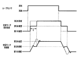
次に、本実施形態のループ制御の方法について説明する。本実施形態のループ制御の特徴は、定着モータの速度を切り替える際、速度のオーバーシュートやアンダーシュートができるだけ発生しないような速度切り替えを行う点にある。図5に示すタイムチャートを参照して本実施形態のループセンサの動作と定着モータの速度制御について説明する。 Next, the loop control method of this embodiment will be described. The feature of the loop control of the present embodiment is that, when switching the speed of the fixing motor, speed switching is performed so that overshoot and undershoot of the speed do not occur as much as possible. The operation of the loop sensor and the speed control of the fixing motor of this embodiment will be described with reference to the time chart shown in FIG.
ここで、定着装置の搬送速度が転写部の搬送速度より遅い場合の定着モータの速度を第1の速度、転写部の搬送速度より速い場合の定着モータの速度を第2の速度と呼び、これらの速度は予め設定されていることとする。定着装置の搬送速度が転写部での搬送速度より遅いとシートはたわんでたわみ(ループ)ができるのでループセンサのレバーを押し倒し、フォトインタラプタは透過状態から遮光状態に変化する。したがって、遮光状態が検知された場合、定着装置の搬送速度を転写部の搬送速度より速く駆動してシートのたわみを解消させる。ここで、速度切り替えの際、定着モータの速度を第1の速度から第2の速度へ一気に切り替えると図5に示す点線のように大きなオーバーシュートが生じ、このオーバーシュートにより転写部の搬送速度と大きな速度差が生じるので画像に悪影響を与えることとなる。なお、ループセンサの状態検知は、レバーの細かな動きにより発生するチャタリングを除去するため、センサが一定時間連続して同じ状態であったらその状態で確定することとする。 Here, the fixing motor speed when the conveyance speed of the fixing device is slower than the conveyance speed of the transfer unit is called a first speed, and the speed of the fixing motor when it is faster than the conveyance speed of the transfer unit is called a second speed. The speed is set in advance. If the conveyance speed of the fixing device is slower than the conveyance speed at the transfer unit, the sheet can bend and bend (loop), so the lever of the loop sensor is pushed down, and the photo interrupter changes from the transmission state to the light shielding state. Accordingly, when the light shielding state is detected, the sheet conveyance is eliminated by driving the conveyance speed of the fixing device faster than the conveyance speed of the transfer unit. Here, when the speed is switched, if the speed of the fixing motor is switched from the first speed to the second speed at once, a large overshoot occurs as shown by a dotted line in FIG. Since a large speed difference occurs, the image is adversely affected. Note that the state detection of the loop sensor eliminates chattering that occurs due to minute movements of the lever, so if the sensor remains in the same state for a certain period of time, it is determined in that state.
本実施形態では、このようなオーバーシュートを減らすため、図5の実線に示すように第1の速度と第2の速度との平均の速度である第3の速度を介し、第1の速度→第3の速度→第2の速度という順に2段階で速度を切り替えるようにする。これにより速度切り替え1回当たりの速度変化幅は半分になるので、オーバーシュート量も小さくなる。本実施形態では、第3の速度で制御している時間tは、定着モータの実速度が第3の速度に達するまでの時間より長くするため、定着モータの実速度が第3の速度に収束し安定する時間に設定しておく。 In the present embodiment, in order to reduce such overshoot, the first speed → the third speed, which is an average speed of the first speed and the second speed, as shown by the solid line in FIG. The speed is switched in two stages in the order of the third speed → the second speed. As a result, the speed change width per speed change is halved, and the amount of overshoot is also reduced. In the present embodiment, the time t controlled at the third speed is longer than the time until the actual speed of the fixing motor reaches the third speed, so the actual speed of the fixing motor converges to the third speed. Set the time to be stable.
次に、定着モータの速度が上がり定着装置の搬送速度が転写部の搬送速度より速くなると、シートのたわみがなくなってくるためループセンサのレバー22が起き上がり、フォトインタラプタ24は透過状態に変化する。透過状態はたわみがない状態を示しているから、今度は定着装置の搬送速度を下げて転写部の搬送速度より遅くし、シートがたわむようにする。この速度切り替えの際も上記と同様に、図5の点線に示すように定着モータの速度を第2の速度から第1の速度へ1度に変えるのではなく、図5の実線に示すように第2の速度→第3の速度→第1の速度の順に2段階で切り替える。このように制御することにより、速度の変化幅が小さくなり、速度切り替え時のアンダーシュート量を抑える事ができる。このように速度切り替えが行われるごとに、ループセンサの動きに合わせて第3の速度を介し速度の切り替えを行う。なお、本実施形態では第1の速度と第2の速度との中間に第3の速度を一つだけ設定したが、複数の中間の速度を設定してもよい。複数の中間の速度を設定するときは、任意の間隔で設定することができ、例えば均等な間隔で設定することによっても本発明の効果を奏することができる。
Next, when the speed of the fixing motor increases and the conveying speed of the fixing device becomes faster than the conveying speed of the transfer unit, the deflection of the sheet disappears, so that the
上記のように、本実施形態では、ループ制御における定着モータの速度切り替えの際、現在の速度と目標速度の平均の速度を設定し、目標速度に切り替える時には間に必ず平均の速度を入れて段階的に切り替える。これにより、速度切り替え時のオーバーシュートやアンダーシュートをより低く抑えられ、それによる画像の劣化を防ぐことが可能となる。 As described above, in this embodiment, when switching the speed of the fixing motor in the loop control, an average speed between the current speed and the target speed is set, and the average speed is always inserted between the speeds when switching to the target speed. Switch. As a result, overshoot and undershoot at the time of speed switching can be suppressed to a lower level, and image deterioration due to this can be prevented.
(第2実施形態)
上記の第1実施形態では、第1の速度から第2の速度に切り替える際、中間の速度を第1の速度と第2の速度との平均速度としたが、本発明の効果を奏するためには平均とする必要はない。そこで本実施形態は、オーバーシュートやアンダーシュートをより減らすように、中間の速度を柔軟に設定することを特徴とする。本実施形態における画像形成装置の構成は、上記第1実施形態と同様であるためその説明は省略する。
(Second Embodiment)
In the first embodiment described above, when switching from the first speed to the second speed, the intermediate speed is the average speed of the first speed and the second speed, but in order to achieve the effects of the present invention. Need not be average. Therefore, the present embodiment is characterized in that the intermediate speed is flexibly set so as to further reduce overshoot and undershoot. Since the configuration of the image forming apparatus in the present embodiment is the same as that in the first embodiment, description thereof is omitted.
図6のタイムチャートを参照して本実施形態について説明する。まず、ループセンサ24が透過状態から遮光状態に変化すると、たわみが生じているから定着モータを第1の速度から第2の速度に切り替えてたわみを解消するようにする。この時、中間の速度を第1の速度と第2の速度の平均速度(第1実施形態での第3の速度)より高速の(第2の速度により近い)第4の速度を設定し、第1の速度→第4の速度→第2の速度という順で2段階に切り替えを行う。なお、第4の速度で制御する時間tは、第1実施形態同様に定着モータの実速度が第4の速度で収束し安定する時間に設定することとする。
This embodiment will be described with reference to the time chart of FIG. First, when the
第1の速度から第4の速度への切り替えは速度変化幅が上記第1実施形態より大きいためこの時のオーバーシュート量は大きくなる。しかし、第4の速度から第2の速度への切り替えは速度変化幅が小さくなるので、オーバーシュート量は小さくすることができる。画像へ影響するのは定着装置の搬送速度と転写部の搬送速度との速度差であるため、全体としてオーバーシュート量を小さくする本実施形態により画像への悪影響をより抑えることが可能となる。すなわち、速度差においては第1の速度から第4の速度でのオーバーシュートの方が、第4の速度から第2の速度でのオーバーシュートより大きいため、画像への悪影響をより抑えることができるのである。 The change from the first speed to the fourth speed has a larger speed change width than the first embodiment, so the overshoot amount at this time becomes large. However, the change from the fourth speed to the second speed has a small speed change width, so the overshoot amount can be reduced. Since it is the speed difference between the conveyance speed of the fixing device and the conveyance speed of the transfer unit that affects the image, the present embodiment in which the overshoot amount is reduced as a whole can further suppress adverse effects on the image. In other words, in the speed difference, the overshoot from the first speed to the fourth speed is larger than the overshoot from the fourth speed to the second speed, so that adverse effects on the image can be further suppressed. It is.
次に、ループセンサが遮光状態から透過状態に変化する場合を説明すると、この場合は第2の速度から第1の速度に切り替えることとなる。この時、中間の速度を第2の速度と第1の速度との平均速度より低速の第5の速度に設定し、第2の速度→第5の速度→第1の速度という順で切り替えを行う。この時も上記と同様に、転写部の搬送速度との速度差が最も大きくなる第5の速度から第1の速度への切り替え時の加速時間が短いためアンダーシュートを小さくすることができるので、画像への悪影響をより抑えることが可能となる。 Next, the case where the loop sensor changes from the light shielding state to the transmission state will be described. In this case, the second speed is switched to the first speed. At this time, the intermediate speed is set to a fifth speed that is lower than the average speed of the second speed and the first speed, and switching is performed in the order of the second speed → the fifth speed → the first speed. Do. At this time, similarly to the above, the undershoot can be reduced because the acceleration time at the time of switching from the fifth speed to the first speed at which the speed difference with the transfer speed of the transfer portion is the largest is short. It is possible to further suppress the adverse effect on the image.
上記のように、本実施形態では定着装置の搬送速度と転写部での搬送速度の速度差が最も大きくなる時のオーバーシュートやアンダーシュートが最小限になるように、速度を切り替える際の中間の速度を非対称に設定する。これにより、定着装置の搬送速度切り替えによる画像の劣化を抑えることが可能となる。 As described above, in the present embodiment, the intermediate speed when switching the speed is minimized so that overshoot and undershoot are minimized when the speed difference between the transport speed of the fixing device and the transport speed at the transfer unit is the largest. Set the speed asymmetrically. As a result, it is possible to suppress image deterioration due to switching of the conveyance speed of the fixing device.
(第3実施形態)
上述のオーバーシュートやアンダーシュートによる画像劣化に加え、ループ制御における定着装置の搬送速度を切り替える際の、速度収束時の速度変動によるショックがシートを介して転写部に伝わって、画像への悪影響が生じる場合がある。本実施形態は、定着モータの速度切り替え時のオーバーシュートやアンダーシュート量を減らすだけでなく、速度切り替えのショックを減らすように制御することを特徴とする。本実施形態における画像形成装置の構成は上記第1実施形態と同様であり、その説明は省略する。
(Third embodiment)
In addition to image degradation due to overshoot and undershoot as described above, when switching the conveyance speed of the fixing device in loop control, a shock due to speed fluctuation at the time of speed convergence is transmitted to the transfer section via the sheet, and there is an adverse effect on the image. May occur. The present embodiment is characterized in that control is performed not only to reduce the amount of overshoot and undershoot when switching the speed of the fixing motor, but also to reduce the shock of speed switching. The configuration of the image forming apparatus in the present embodiment is the same as that in the first embodiment, and a description thereof will be omitted.
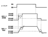
図7のタイムチャートを参照して、上記第1実施形態と比較しながら本実施形態について説明する。第1実施形態では、図7の点線のように例えばループセンサが透過状態から遮光状態へ変化し、定着モータを第1の速度から第2の速度へ切り替える際、その中間の速度である第3の速度で駆動する時間は、実速度が第3の速度に収束し安定するまでであった。これに対し、本実施形態では図7の実線のように第3の速度で駆動している時間tを、実速度が第3の速度に収束するより短い時間とする。ここでは実速度が第3の速度を越えオーバーシュートの頂点付近に達するまでの時間を予め測定しておき、その時間に設定する。これにより実速度が第3の速度に到達して収束する前に第2の速度に目標速度を切り替えることとなり、第3の速度で速度が収束する時の速度変動によるショックを小さくすることができる。さらに、わずかな時間でも1度第3の速度とすることで第3の速度到達時にモータへ減速信号が送信され加速が弱まるので、第1の速度から第2の速度へ1度に切り替えるよりオーバーシュートの量を小さくすることができる。なお、ここでは中間の速度として第1の速度と第2の速度の平均である第3の速度としたが、これに限る必要はなく、例えば第2実施形態の第4の速度や第5の速度を使用してもよい。 With reference to the time chart of FIG. 7, the present embodiment will be described in comparison with the first embodiment. In the first embodiment, as indicated by the dotted line in FIG. 7, for example, the loop sensor changes from the transmission state to the light shielding state, and when the fixing motor is switched from the first speed to the second speed, The time for driving at this speed was until the actual speed converged to the third speed and stabilized. On the other hand, in the present embodiment, the time t during driving at the third speed as shown by the solid line in FIG. 7 is set to be shorter than the time at which the actual speed converges to the third speed. Here, the time until the actual speed exceeds the third speed and reaches the vicinity of the top of the overshoot is measured in advance and set to that time. As a result, the target speed is switched to the second speed before the actual speed reaches the third speed and converges, and the shock due to speed fluctuation when the speed converges at the third speed can be reduced. . Furthermore, since the deceleration signal is transmitted to the motor when the third speed is reached by setting the third speed once even for a short time, the acceleration is weakened. Therefore, it is more than switching from the first speed to the second speed. The amount of chute can be reduced. Here, the intermediate speed is the third speed, which is the average of the first speed and the second speed, but is not limited to this. For example, the fourth speed or the fifth speed of the second embodiment Speed may be used.
上記のように、本実施形態では、定着モータの速度切り替えの際、中間の速度に設定する時間を実際の速度が中間の速度で収束し安定する時間より短くするようにする。これにより、速度切り替えによるショックがシートに伝わる回数を減らすことができ、さらに目標速度でのオーバーシュートやアンダーシュートの量も減らすことができる。 As described above, in this embodiment, when the speed of the fixing motor is switched, the time for setting the intermediate speed is set shorter than the time for the actual speed to converge and stabilize at the intermediate speed. As a result, the number of times the shock due to speed switching is transmitted to the seat can be reduced, and the amount of overshoot and undershoot at the target speed can also be reduced.
9 感光ドラム
10 転写ローラ
15 定着装置
16 定着ローラ
17 加圧ローラ
20 ループセンサ
31 モータ制御IC
46 CPU
9
46 CPU
Claims (8)
記録材が搬送される搬送路上に配置され、記録材を搬送する第1の搬送手段と、
前記搬送路上の前記第1の搬送手段より下流側に配置され、前記第1の搬送手段によって搬送された記録材を搬送する第2の搬送手段と、
前記第1の搬送手段と第2の搬送手段との間に配置され、前記搬送路上を搬送される記録材のたわみを検出する検出手段と、
前記検出手段の検出結果に応じて、前記第2の搬送手段を第1の速度と、第1の速度と異なる第2の速度とに切り替えて駆動し、記録材の搬送を制御する制御手段と
を備え、前記制御手段は、フィードバック制御によるサーボモータで駆動され、前記第1の速度と前記第2の速度とを切り替える場合、前記第2の搬送手段を前記第1の速度から前記第1の速度および前記第2の速度との間の速度である第3の速度に切り替え、前記第3の速度で一定時間駆動し、前記第3の速度から前記第2の速度に切り替えることで、前記第2の速度に切り替える際の速度の変化幅を小さくすることを特徴とする画像形成装置。 An image forming apparatus of making images on a recording material,
Disposed on the transport path of the recording material is conveyed, a first conveying means for conveying the record member,
A second conveying unit disposed on the downstream side of the first conveying unit on the conveying path and configured to convey the recording material conveyed by the first conveying unit;
A detecting unit disposed between the first conveying unit and the second conveying unit, and detecting a deflection of the recording material conveyed on the conveying path;
In accordance with a detection result of said detecting means, said second conveying means and the first speed, switch to the second speed different from the first speed drive, control means for controlling the transport of the record material The control means is driven by a servo motor by feedback control , and when switching between the first speed and the second speed, the second transport means is moved from the first speed to the first speed . speed and switched to the third speed of the Ru velocity der between the second speed, a certain time driving in the third speed, by switching from the third speed to the second speed, An image forming apparatus, wherein a change width of a speed when switching to the second speed is reduced .
前記第2の搬送手段は、前記転写手段によって転写された画像を前記記録材に定着する定着手段であることを特徴とする請求項1乃至7のいずれかに記載の画像形成装置。 The first conveying means is a transfer means for transferring an image to the recording material;
It said second conveying means, an image forming apparatus according to any one of claims 1 to 7, characterized in that the image transferred by said transfer means is a fixing means for fixing to the recording material.
Priority Applications (1)
| Application Number | Priority Date | Filing Date | Title |
|---|---|---|---|
| JP2006030219A JP4920987B2 (en) | 2006-02-07 | 2006-02-07 | Image forming apparatus |
Applications Claiming Priority (1)
| Application Number | Priority Date | Filing Date | Title |
|---|---|---|---|
| JP2006030219A JP4920987B2 (en) | 2006-02-07 | 2006-02-07 | Image forming apparatus |
Publications (3)
| Publication Number | Publication Date |
|---|---|
| JP2007212583A JP2007212583A (en) | 2007-08-23 |
| JP2007212583A5 JP2007212583A5 (en) | 2009-03-26 |
| JP4920987B2 true JP4920987B2 (en) | 2012-04-18 |
Family
ID=38491106
Family Applications (1)
| Application Number | Title | Priority Date | Filing Date |
|---|---|---|---|
| JP2006030219A Expired - Fee Related JP4920987B2 (en) | 2006-02-07 | 2006-02-07 | Image forming apparatus |
Country Status (1)
| Country | Link |
|---|---|
| JP (1) | JP4920987B2 (en) |
Families Citing this family (2)
| Publication number | Priority date | Publication date | Assignee | Title |
|---|---|---|---|---|
| JP5367676B2 (en) * | 2010-11-10 | 2013-12-11 | 株式会社沖データ | Image forming apparatus |
| JP2023005384A (en) | 2021-06-29 | 2023-01-18 | 京セラドキュメントソリューションズ株式会社 | Image forming apparatus |
Family Cites Families (6)
| Publication number | Priority date | Publication date | Assignee | Title |
|---|---|---|---|---|
| JPH07181830A (en) * | 1993-12-22 | 1995-07-21 | Canon Inc | Image forming device |
| JPH1097154A (en) * | 1996-09-19 | 1998-04-14 | Canon Inc | Image forming device |
| JPH1124498A (en) * | 1997-07-04 | 1999-01-29 | Fuji Xerox Co Ltd | Image forming device |
| JP2000089534A (en) * | 1998-09-14 | 2000-03-31 | Minolta Co Ltd | Image forming device |
| JP2005077613A (en) * | 2003-08-29 | 2005-03-24 | Canon Inc | Image forming apparatus |
| JP2005338161A (en) * | 2004-05-24 | 2005-12-08 | Canon Inc | Image forming apparatus |
-
2006
- 2006-02-07 JP JP2006030219A patent/JP4920987B2/en not_active Expired - Fee Related
Also Published As
| Publication number | Publication date |
|---|---|
| JP2007212583A (en) | 2007-08-23 |
Similar Documents
| Publication | Publication Date | Title |
|---|---|---|
| US20070286656A1 (en) | Image forming apparatus and conveyance malfunction decision method | |
| US7547016B2 (en) | Motor control apparatus with controlled input current | |
| US6564025B2 (en) | Image forming apparatus with recording material convey velocity control feature | |
| JPH09175694A (en) | Sheet conveying device | |
| JP6012919B1 (en) | Motor control device, sheet conveying device, and image forming apparatus | |
| JP2017138545A (en) | Image forming apparatus | |
| JP2010271405A (en) | Image forming apparatus | |
| US9420134B2 (en) | Image forming apparatus having a control unit to control and move a read unit | |
| JP6578961B2 (en) | Sheet conveying apparatus, image processing apparatus, and sheet conveying control method | |
| JP4920987B2 (en) | Image forming apparatus | |
| US11319178B2 (en) | Sheet conveyance apparatus and image forming apparatus | |
| JP2007298872A (en) | Image forming apparatus | |
| JP4795204B2 (en) | Sheet conveying apparatus, image forming apparatus, and image reading apparatus | |
| US9921535B2 (en) | Motor driving device, sheet conveying device, and image forming apparatus | |
| JP2010054819A (en) | Color image forming apparatus | |
| US11673756B2 (en) | Image forming apparatus and sheet conveyance apparatus | |
| JP2006211879A (en) | Information processing apparatus and motor controlling method | |
| US9086659B2 (en) | Image forming apparatus | |
| JP2018121523A5 (en) | Motor control device, sheet conveying device, document feeding device, document reading device, and image forming device | |
| JP2007206406A (en) | Image forming apparatus | |
| JP6156731B2 (en) | Belt drive device and image forming apparatus using the same | |
| US20220380164A1 (en) | Reading apparatus, conveying operation control method and storage medium | |
| JP2017203875A (en) | Image forming device | |
| JP6308164B2 (en) | Image forming apparatus | |
| JP2006227298A (en) | Image forming apparatus and method of controlling image forming apparatus |
Legal Events
| Date | Code | Title | Description |
|---|---|---|---|
| A521 | Request for written amendment filed |
Free format text: JAPANESE INTERMEDIATE CODE: A523 Effective date: 20090209 |
|
| A621 | Written request for application examination |
Free format text: JAPANESE INTERMEDIATE CODE: A621 Effective date: 20090209 |
|
| RD02 | Notification of acceptance of power of attorney |
Free format text: JAPANESE INTERMEDIATE CODE: A7422 Effective date: 20101106 |
|
| A977 | Report on retrieval |
Free format text: JAPANESE INTERMEDIATE CODE: A971007 Effective date: 20110608 |
|
| A131 | Notification of reasons for refusal |
Free format text: JAPANESE INTERMEDIATE CODE: A131 Effective date: 20110610 |
|
| A521 | Request for written amendment filed |
Free format text: JAPANESE INTERMEDIATE CODE: A523 Effective date: 20110809 |
|
| TRDD | Decision of grant or rejection written | ||
| A01 | Written decision to grant a patent or to grant a registration (utility model) |
Free format text: JAPANESE INTERMEDIATE CODE: A01 Effective date: 20120127 |
|
| A01 | Written decision to grant a patent or to grant a registration (utility model) |
Free format text: JAPANESE INTERMEDIATE CODE: A01 |
|
| A61 | First payment of annual fees (during grant procedure) |
Free format text: JAPANESE INTERMEDIATE CODE: A61 Effective date: 20120202 |
|
| R151 | Written notification of patent or utility model registration |
Ref document number: 4920987 Country of ref document: JP Free format text: JAPANESE INTERMEDIATE CODE: R151 |
|
| FPAY | Renewal fee payment (event date is renewal date of database) |
Free format text: PAYMENT UNTIL: 20150210 Year of fee payment: 3 |
|
| LAPS | Cancellation because of no payment of annual fees |