JP4919829B2 - Silencer - Google Patents
Silencer Download PDFInfo
- Publication number
- JP4919829B2 JP4919829B2 JP2007029382A JP2007029382A JP4919829B2 JP 4919829 B2 JP4919829 B2 JP 4919829B2 JP 2007029382 A JP2007029382 A JP 2007029382A JP 2007029382 A JP2007029382 A JP 2007029382A JP 4919829 B2 JP4919829 B2 JP 4919829B2
- Authority
- JP
- Japan
- Prior art keywords
- silencer
- sound
- sound wave
- opening
- air passage
- Prior art date
- Legal status (The legal status is an assumption and is not a legal conclusion. Google has not performed a legal analysis and makes no representation as to the accuracy of the status listed.)
- Expired - Fee Related
Links
- 230000003584 silencer Effects 0.000 title claims description 61
- 238000009423 ventilation Methods 0.000 claims description 34
- 239000011358 absorbing material Substances 0.000 claims description 7
- 230000007423 decrease Effects 0.000 claims description 4
- 239000000463 material Substances 0.000 claims description 3
- 238000010276 construction Methods 0.000 description 6
- 230000000694 effects Effects 0.000 description 4
- 230000030279 gene silencing Effects 0.000 description 4
- 230000001743 silencing effect Effects 0.000 description 4
- 238000009413 insulation Methods 0.000 description 3
- 230000035699 permeability Effects 0.000 description 3
- 238000004080 punching Methods 0.000 description 3
- 239000011796 hollow space material Substances 0.000 description 2
- 230000009467 reduction Effects 0.000 description 2
- JOYRKODLDBILNP-UHFFFAOYSA-N Ethyl urethane Chemical compound CCOC(N)=O JOYRKODLDBILNP-UHFFFAOYSA-N 0.000 description 1
- 230000009471 action Effects 0.000 description 1
- 230000004888 barrier function Effects 0.000 description 1
- 238000005452 bending Methods 0.000 description 1
- 239000002657 fibrous material Substances 0.000 description 1
- 239000011491 glass wool Substances 0.000 description 1
- 230000017525 heat dissipation Effects 0.000 description 1
- 238000009434 installation Methods 0.000 description 1
- 230000001788 irregular Effects 0.000 description 1
- 239000002184 metal Substances 0.000 description 1
- 238000005555 metalworking Methods 0.000 description 1
- 239000011148 porous material Substances 0.000 description 1
- 239000011347 resin Substances 0.000 description 1
- 229920005989 resin Polymers 0.000 description 1
- 230000004044 response Effects 0.000 description 1
Images
Landscapes
- Building Environments (AREA)
- Special Wing (AREA)
- Soundproofing, Sound Blocking, And Sound Damping (AREA)
- Specific Sealing Or Ventilating Devices For Doors And Windows (AREA)
- Accessory Devices And Overall Control Thereof (AREA)
Description
本発明は、建築構造物の壁面に設けるガラリ構造体に関するもので、特にガラリ構造体を構成する複数の羽根体の間に形成する通気路を通じてガラリ構造体の一方の側にある騒音源から他方の側へ伝わる騒音音波を低減させる消音装置に関する。 The present invention relates to a gallery structure provided on a wall surface of a building structure, and in particular from a noise source on one side of the gallery structure through an air passage formed between a plurality of blade bodies constituting the gallery structure. It is related with the silencer which reduces the noise sound wave transmitted to the side.
従来、自動車、工事現場、その他の騒音源から発生する騒音を防ぐ手段の一つとして防音壁が良く知られている。透光性の樹脂板や金属部材からなる壁体を道路脇や工事現場の周囲に設置し、壁の片側で発生する騒音が他方の側へ直接伝わらないようにするものであり、壁の高さを高くするほど遮音効果が上がるとされ、その高さはますます高まる傾向にある。 Conventionally, a noise barrier is well known as one of means for preventing noise generated from automobiles, construction sites, and other noise sources. Walls made of translucent resin plates and metal members are installed on the side of the road and around the construction site so that noise generated on one side of the wall is not directly transmitted to the other side. It is said that the sound insulation effect increases as the height increases, and the height tends to increase more and more.
ところで、騒音源の種類には上記の他にも産業機械、空調室外機など建物構造物に付随する形で固定設置されるものがあり、そのような騒音源の多くは外気に対しての通気性や換気性を確保し、騒音源たる機械装置の稼働に伴って発生する熱を放熱させる必要がある。防音性を最優先すれば、本来は、騒音源が有る側と無い側とを完全に遮断する壁体を設置するのが望ましいのであるが、放熱の問題を無視することはできないため、周囲を覆う壁の一部分をガラリ構造とすることで、ある程度の遮音効果と通気性の両方を兼ね備えるようにしている。 By the way, in addition to the above types of noise sources, there are those that are fixedly installed in association with building structures such as industrial machines and air conditioner outdoor units, and many such noise sources are ventilated to the outside air. It is necessary to ensure heat and ventilation and to dissipate the heat generated by the operation of the mechanical device that is the noise source. If soundproofing is given top priority, it is desirable to install a wall that completely blocks the side with and without the noise source, but the problem of heat dissipation cannot be ignored. A part of the covering wall has a glazed structure, so that both a certain sound insulation effect and air permeability are provided.
例えば下記特許文献1には、中空にした扉本体内部をセパレータで分割してダクトを構成すると共に、ダクト内面に吸音材を貼り付け、ダクト端部の扉表面と裏面の各々にガラリを取り付けたガラリ扉が開示されている。この先行例によれば、扉の一方のガラリから侵入した騒音はダクトによって遮音され、さらにダクト内において吸音材によって吸音されることによりガラリを備えながら扉としての消音が可能になる。
上記先行例によれば、通気性を確保しながら扉の一方の側から他方の側に対しての消音が可能になる。しかし、扉本体内部を中空構造にしてダクトを形成し、そのダクト自体を消音空間としながらダクト端部にガラリを取り付けているので、その構造は扉全体にわたっており、ガラリとして単独で扱えるものではなかった。したがって、コストが嵩むのはもちろんのこと、施工場所に対する汎用性に欠けるという問題を抱えていた。また、施工に際しては、表面に現れるガラリの大きさに対して相当大きな取付スペースを必要とするため、施工作業に手間を要するうえ換気効率の点からしても優れているとは言えなかった。 According to the preceding example, it is possible to mute the door from one side to the other side while ensuring air permeability. However, since the door body has a hollow structure and a duct is formed, and the duct itself is a silencing space, and the louver is attached to the end of the duct, the structure covers the entire door and cannot be handled alone as a louver. It was. Therefore, not only the cost is increased, but there is a problem that the construction site is not versatile. Moreover, since a considerably large installation space is required for the size of the glazing that appears on the surface, the construction work is time-consuming and cannot be said to be excellent in terms of ventilation efficiency.
本発明は上記先行例が抱える問題点に対処してなされたものであり、壁を構成するガラリ構造体の一方の側にある騒音源から他方の側へ伝わる騒音音波を低減させる消音装置において、優れた施工性と通気性を備えながら同時に遮音性を備えた消音装置を提供できないかという点を課題としている。 The present invention was made in response to the problems of the preceding examples, and in a silencer for reducing noise sound waves transmitted from a noise source on one side of a gallery structure constituting a wall to the other side, It is an issue whether it is possible to provide a silencer that has excellent workability and air permeability while at the same time having sound insulation.
本発明は上記課題を解決するために、複数の羽根体の間に形成する通気路を通じて建物内外の換気を行うガラリ構造体であって、通気路を通過する騒音音波の音圧を低減させるようにしたガラリ構造の消音装置において、前記羽根体は、中空構造の内側空間に吸音材を内装してなる消音部と、該消音部の中へ音波を導く音波導入部と、前記消音部の内側空間と外側とを連通する消音部開口とを備え、前記通気路の両端から取付位置をずらして一対の消音部を形成すると共にそれぞれの消音部を前記音波導入部で一体に接続することで、隣り合う羽根体の間にクランク状の屈曲部を有する通気路を形成し、通気路の屈曲する位置に前記消音部開口を臨ませることを特徴とする消音装置を提案する。 In order to solve the above problems, the present invention is a gallery structure that ventilates the inside and outside of a building through an air passage formed between a plurality of blades, and reduces the sound pressure of noise sound waves that pass through the air passage. In the louvered structure silencer, the blade body includes a sound deadening portion in which a sound absorbing material is housed in an inner space of a hollow structure, a sound wave introducing portion for guiding sound waves into the sound deadening portion, and an inner side of the sound deadening portion. With a muffler opening that communicates the space and the outside, by shifting the mounting position from both ends of the ventilation path to form a pair of muffler parts and connecting each muffler part integrally with the sound wave introduction part , There is proposed a silencer characterized in that an air passage having a crank-shaped bent portion is formed between adjacent blade bodies, and the opening of the silencer portion is made to face the position where the air passage is bent .
上記提案の消音装置は、前記音波導入部を、曲面を有する板状部材で形成することが望ましい。 In the proposed silencer, it is desirable that the sound wave introduction portion is formed of a plate-like member having a curved surface.
また、上記提案の消音装置は、前記音波導入部を形成する板状部材の端部を前記消音部開口の開口縁部に固定することが望ましい。 In the proposed silencer, it is preferable that the end of the plate-like member forming the sound wave introduction portion is fixed to the opening edge of the silencer opening.
また、前記消音部開口の開口寸法が開口縁部から前記消音部の内側空間に向かって漸次縮小する形状であることが望ましい。 In addition, it is desirable that the opening size of the opening of the silencer gradually decreases from the opening edge toward the inner space of the silencer.
また、前記通気路に臨む前記消音部の側面の少なくとも一部を音波透過性の板材で構成することが望ましい。 Further, it is desirable that at least a part of the side surface of the muffler facing the air passage is made of a sound-transmitting plate material.
本発明では、通気路を区切る羽根体に消音部と音波導入部を設け、この消音部を通気路の両端から取付位置をずらしながら取り付けてそれぞれの消音部を音波導入部で一体に接続している。こうした構造の羽根体同士の間に形成される通気路は、途中でクランク状の屈曲部を備えることになり、通気路の一端から進入した騒音音波は屈曲部において音波導入部から消音部開口を介して消音部の中へと導入される。従って、通気路自体に消音機能の役割を持たせる必要が無くなり、通気路を専ら空気の流れる通路として使用し、通気の際に新鮮な空気と共に進入してくる騒音音波を通気路とは別に設けた消音部の中へ導いて消音を図ることができる。また、施工表面に現れるガラリの寸法内に装置全体を収めていることから、大がかりな施工工事が不要になり、外装部材・外装部品として汎用的に幅広く使用することができる。 In the present invention, a silencer and a sound wave introduction part are provided on a blade body that divides the air passage, and the silencer is attached while shifting the attachment position from both ends of the air passage, and the respective sound silencers are integrally connected by the sound wave introduction part. Yes. The air passage formed between the blades having such a structure is provided with a crank-shaped bent portion in the middle, and the noise sound wave that has entered from one end of the air passage passes through the silencer opening from the sound wave introduction portion in the bent portion. It is introduced into the silencer. Therefore, it is no longer necessary to provide the silencing function for the air passage itself, and the air passage is used exclusively as a passage through which air flows, and noise sound waves that enter with fresh air are provided separately from the air passage during ventilation. The sound can be silenced by guiding it into the muffler. In addition, since the entire apparatus is accommodated within the dimensions of the glazing that appears on the construction surface, no extensive construction work is required, and it can be widely used as exterior members and exterior parts.
また、通気路の両端から設けた消音部を、曲面を有する板状部材からなる音波導入部で接続し、通気路の中に入り込んだ騒音音波を曲面で反射させて消音部内へ導くので、騒音音波を曲面の焦点付近に集めるようにして効率良く導くことができる。この場合、音波導入部を形成する板状部材の端部を消音部開口の開口縁部に固定することにより、音波導入部の曲面で反射させた騒音音波をより効率良く消音部開口に集めることができ、ひいては消音効果の向上を図ることができる。 In addition, the silencer provided from both ends of the air passage is connected by the sound wave introduction part made of a plate-like member having a curved surface, and the noise sound wave entering the air passage is reflected by the curved surface and guided into the silencer part. The sound waves can be efficiently guided by being collected near the focal point of the curved surface. In this case, by fixing the edge of the plate-like member forming the sound wave introduction part to the opening edge of the muffler opening, the noise sound wave reflected by the curved surface of the sound wave introduction part is collected more efficiently in the muffler opening. As a result, the silencing effect can be improved.
また、消音部開口の開口寸法が開口縁部から消音部の内側空間に向かって徐々に小さくなる形状とすることにより、騒音音波が内側空間に入り込む方向の開口端の断面積に比べて、騒音音波が内側空間から外へ出て行く方向の開口端の断面積が小さくなり、従って、消音部の中へ捕らえた騒音音波が再び外へ漏れ出す現象の発生を抑制することができる。 In addition, the shape of the opening of the silencer opening gradually decreases from the edge of the opening toward the inner space of the silencer, thereby reducing the noise compared to the sectional area of the opening end in the direction in which the noise sound wave enters the inner space. The cross-sectional area of the opening end in the direction in which the sound wave goes out from the inner space is reduced, and therefore, it is possible to suppress the occurrence of the phenomenon that the noise sound wave trapped in the silencer leaks out again.
また、通気路に臨む消音部の側面の少なくとも一部を音波透過性の板材で構成することにより、消音部の中へ取り込む騒音音波を増やすことができ、消音効果を向上させることができる。
以下、本発明の好適な実施形態について図面を参照しながら説明する。
In addition, by forming at least a part of the side surface of the silencer facing the air passage with a sound-transmitting plate material, it is possible to increase the noise sound wave taken into the silencer and improve the silence effect.
Preferred embodiments of the present invention will be described below with reference to the drawings.
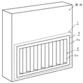
図1は本発明実施例に関わる消音装置の外観を示す説明図である。1は本発明に係る消音装置であり、いわゆるガラリ構造を備えている。2は通風口であり、本体ケーシング3の側面3a及び側面3b(図示しない)に対して左右方向に複数設けている。図1の手前側に現れるのは騒音側通風口2aであり、本消音装置を設置する際にはこの騒音側通風口2aを騒音源の存在する側に向けて設置する。なお、図1には現れていないが、側面3bには静音側通風口2bが設けられている。
FIG. 1 is an explanatory view showing the appearance of a silencer according to an embodiment of the present invention.
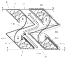
次に本発明の断面構造について図2を基に説明する。図2は図1に示す消音装置1の水平方向断面を示した説明図であり、特にその一部を示している。4は羽根体であり、左右方向に並べて形成する複数の通風口2a・2bの間を区切ると共に、騒音側通風口2aと静音側通風口2bとの間を連通する通気路5を形成している。この羽根体4は、中空構造からなる消音部4−1と、板状部材からなる音波導入部4−2とを備えており、騒音側通風口2a及び静音側通風口2bの開口部分からそれぞれ通気路5の内側に向かって消音部4−1が傾斜した形状で取り付けられ、通気路5の中心付近で向かい合う2つの消音部4−1を音波導入部4−2で接続している。騒音側通風口2a及び静音側通風口2bの開口部分に取り付ける2つの消音部4−1は、それぞれの中心を通る中心軸が同一直線上に並ばない位置関係、即ちずれた状態で取り付けており、従って羽根体4の全体形状は音波導入部4−2において屈曲した形状を呈している。そして、本体ケーシング3の横方向に取り付けられる複数の羽根体4は一様に上記形状を備えており、その結果、羽根体と羽根体との間に形成される通気路5も途中にクランク状の屈曲部を持つ形状となっている。
Next, the cross-sectional structure of the present invention will be described with reference to FIG. FIG. 2 is an explanatory view showing a horizontal section of the
消音部4−1の内側には中空の空間が形成されており、その中空空間にはグラスウール等の繊維質材やウレタン等の多孔質材からなる吸音材6を収容して消音室4−1aを構成している。4−1bは消音部開口であり、この開口を通じて消音室4−1aと通気路5とを連通している。4−2a・4−2bは、音波導入部を構成する音波反射板であり、その反射面が騒音側通風口2aを向く位置に音波反射板4−2aが取り付けられ、同じく静音側通風口2bを向く位置には音波反射板4−2bが取り付けられている。そして、これら音波反射板4−2a・4−2bは、一対の消音部4−1の一方の側端から他方の消音部開口4−1bにわたって延設し、通気路5に進入してくる騒音音波を消音室4−1aの内部へ反射するようにしている。音波反射板4−2a・4−2bは、その断面が楕円曲線を描くよう曲面形状に形成されており、楕円形状に基づく焦点の1つ(図中f1)を消音部開口4−1bに合わせ、もう一方の焦点(図中f2)を通気路5の経路中に設定することにより、通気路内に換気空気と共に進入した騒音音波を音波反射板4−2a・4−2bで反射させ、焦点f1からf2を経て消音室4−1a内部へ導くのである。消音部開口4−1bは、音波反射板4−2a・4−2bに向かって開口する開口縁の部分から消音室4−1aの内部に向かって、開口寸法が徐々に縮小する形状を備えている。消音部4−1の側面を形成する板状部材の端部と、音波反射板4−2a・4−2bに連続する端部を、消音部開口4−1bの端部において消音室内4−1a内に向けて斜めに折り返すことで開口寸法を漸次狭めるようにしており、音波反射版4−2a・4−2bで反射して消音室4−1a内に入り込んだ騒音音波が消音室内から外へ向かって出て行きにくい構造としている。な
お、図2では、焦点f1を消音部開口4−1bの略中央に設定し、焦点f2を通気路5内の消音部開口4−1b近傍に設定しているが、必ずしも図示の位置に限定される必要はない。例えば、消音部開口4−1bの縁部で消音室内へ向けて斜めに折り返しているエッジ部分に焦点f1を設定し、焦点f2を騒音側通風口2aの近傍に設定しても良い。要は、焦点f1が消音部開口4−1bの近傍位置に有り、焦点f2が通気路5の経路中に有ればよい。
A hollow space is formed inside the sound deadening portion 4-1, and a sound absorbing material 6 made of a fibrous material such as glass wool or a porous material such as urethane is accommodated in the hollow space and the sound deadening chamber 4-1a. Is configured. Reference numeral 4-1b denotes a muffler opening, and the muffler chamber 4-1a and the air passage 5 are communicated with each other through the opening. 4-2a and 4-2b are sound wave reflecting plates constituting the sound wave introducing portion, and a sound wave reflecting plate 4-2a is attached to a position where the reflecting surface faces the noise
ところで、騒音側通風口2aの側に位置する消音部4−1の消音部開口4−1bにつながる側面4−1cは、多数の抜き孔が設けられたパンチングプレートによって形成されており、多数の抜き孔を通じて消音室4−1aと通気路5とを連通させている。こうした構造により、騒音側通風口2aから進入した騒音音波はパンチングプレートの表面に衝突して抜き孔の部分においてホイヘンスの原理により新たな音源が発生し、回折現象を伴って抜き孔から消音室4−1aの内部へと入り込む為、その分、騒音エネルギーの低減効果を向上させることが可能になる。
By the way, the side surface 4-1c connected to the muffler opening 4-1b of the muffler 4-1 located on the
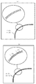
ここで、音波反射板4−2a・4−2bの断面形状について説明する。本実施例では、音波反射板4−2a・4−2bの断面形状として楕円形状を与えているが、図3に示すように、金型を用いるなどして平板楕円形に形成した連続楕円曲線と(図3(a))、板金加工機械によって平板を細かく折り曲げ加工して形成した近似的な楕円曲線(図3(b))の何れを採用しても良い。連続的した楕円曲線にした場合には、その焦点f1およびf2の範囲がより狭い範囲で正確になり、擬似的な楕円曲線にした場合には、焦点f1・f2の範囲が若干広がってその輪郭があいまいになるものの、両者の差は本装置の消音効果を得る上で十分に許容できる程度のものである。また、楕円形状に限定する必要がないことは言うまでもない。例えば、円、放物線、双曲線といった曲線を採用することも可能であり、その場合は各曲線の中心点や焦点の位置を図2に示すf1の付近に設定すればよい。更に、音波反射板4−2a・4−2bの断面形状を曲線ではなく平板を数カ所で折り曲げた形状としてもよい。例えば、平らな板を一箇所で曲げて略「く」字状の断面形状とすることもできる。その場合、音波反射板4−2a・4−2bは焦点を持たないため消音室内へ騒音音波を誘引する効率は低下するものの、焦点の位置合わせといった寸法管理が不要になり比較的自由な設計を行うことが可能になる。 Here, the cross-sectional shape of the sound wave reflection plates 4-2a and 4-2b will be described. In this embodiment, an elliptical shape is given as the cross-sectional shape of the sound wave reflecting plates 4-2a and 4-2b. However, as shown in FIG. 3, a continuous elliptic curve formed into a flat elliptical shape by using a mold or the like. (FIG. 3 (a)), an approximate elliptic curve (FIG. 3 (b)) formed by finely bending a flat plate by a sheet metal working machine may be adopted. In the case of a continuous elliptic curve, the range of the focal points f1 and f2 is accurate in a narrower range, and in the case of a pseudo elliptic curve, the range of the focal points f1 and f2 is slightly widened and the contour thereof is increased. However, the difference between the two is sufficiently acceptable to obtain the silencing effect of the present apparatus. Needless to say, it is not necessary to limit to an elliptical shape. For example, it is possible to adopt a curve such as a circle, a parabola, or a hyperbola, and in this case, the center point of each curve and the position of the focus may be set near f1 shown in FIG. Furthermore, the cross-sectional shape of the sound wave reflection plates 4-2a and 4-2b may be a shape in which a flat plate is bent at several places instead of a curved line. For example, a flat plate can be bent at one location to have a substantially “<”-shaped cross section. In that case, the sound wave reflectors 4-2a and 4-2b do not have a focus, so the efficiency of attracting noise sound waves into the muffler chamber is reduced. It becomes possible to do.
次に本発明実施例の動作について説明する。外部の騒音源(図示しない)から到達した騒音音波が騒音側通風口2aから通気路5内に進入すると、進入した騒音音波はまず音波反射板4−2aに衝突して消音部開口4−1bに向けて反射を起こし消音室4−1aの内部へと導入される。このとき、反射を起こした騒音音波は、消音部開口4−1bの開口縁の部分などに衝突してホイヘンスの原理により新たな音源が発生したり、回折現象が発生するなどして音波の進む方向が乱れた状態となって消音室内へと導入されることになる。そして消音室4−1aに入り込んだ騒音音波は、消音室内で消音室内で乱反射を繰り返すことによって位相がずれた反射波同士が出合ってエネルギーを打ち消し合ったり、あるいは吸音材6の作用で音波の持つエネルギーが低減される結果、騒音音波のエネルギーが大幅に減少して消音効果が得られる。ところで、騒音側通風口2aから通気路5内に進入した騒音音波のうち側面4−1cに衝突した騒音音波は、既に説明したようにパンチングプレートの抜き孔を通じて消音室4−1aに進入するので、消音室内において上記同様に消音作用が生じる。
Next, the operation of the embodiment of the present invention will be described. When a noise sound wave that has arrived from an external noise source (not shown) enters the air passage 5 from the noise
騒音側通風口2aに近い位置の消音部4−1に捕捉されることなく通気路5内を進んでいく騒音音波は、同じ通気路5を形成している隣の羽根体の音波反射板4−2bに衝突し、今度は静音側通風口2bに近い位置の消音部4−1が内包する消音室4−1aに入り込んで上記同様にして騒音エネルギーが低減化される。そして、騒音音波の騒音エネルギーが取り除かれた換気用の空気が静音側通風口2bから本体ケーシング3の側面3b側へと供給される。
Noise sound waves traveling in the air passage 5 without being captured by the silencer 4-1 at a position close to the noise
1 消音装置本体
2 通風口
2a 騒音側通風口
2b 静音側通風口
3 本体ケーシング
4 羽根体
4−1 消音部
4−1a 消音室
4−1b 消音部開口
4−1c 側面
4−2 音波導入部
4−2a 音波反射板
4−2b 音波反射板
5 通気路
6 吸音材
DESCRIPTION OF
Claims (5)
前記羽根体は、中空構造の内側空間に吸音材を内装してなる消音部と、該消音部の中へ音波を導く音波導入部と、前記消音部の内側空間と外側とを連通する消音部開口とを備え、前記通気路の両端から取付位置をずらして一対の消音部を形成すると共にそれぞれの消音部を前記音波導入部で一体に接続することで、隣り合う羽根体の間にクランク状の屈曲部を有する通気路を形成し、通気路の屈曲する位置に前記消音部開口を臨ませることを特徴とする消音装置。 In a louver structure that ventilates the inside and outside of a building through an air passage formed between a plurality of blades, and in a louver structure silencer that reduces the sound pressure of a noise sound wave that passes through the air passage,
The blade body includes a sound deadening portion in which a sound absorbing material is housed in an inner space of a hollow structure, a sound wave introduction portion that guides sound waves into the sound deadening portion, and a sound deadening portion that communicates the inner space and the outside of the sound deadening portion. And a pair of silencers formed by shifting the mounting positions from both ends of the air passage, and each silencer is integrally connected by the sound wave introduction part, thereby forming a crank shape between adjacent blade bodies. A silencer characterized in that an air passage having a bent portion is formed, and the opening of the silencer is exposed at a position where the air passage is bent .
Priority Applications (2)
| Application Number | Priority Date | Filing Date | Title |
|---|---|---|---|
| JP2007029382A JP4919829B2 (en) | 2007-02-08 | 2007-02-08 | Silencer |
| CN200810003068XA CN101240684B (en) | 2007-02-08 | 2008-01-18 | Silencing apparatus |
Applications Claiming Priority (1)
| Application Number | Priority Date | Filing Date | Title |
|---|---|---|---|
| JP2007029382A JP4919829B2 (en) | 2007-02-08 | 2007-02-08 | Silencer |
Publications (2)
| Publication Number | Publication Date |
|---|---|
| JP2008196124A JP2008196124A (en) | 2008-08-28 |
| JP4919829B2 true JP4919829B2 (en) | 2012-04-18 |
Family
ID=39755318
Family Applications (1)
| Application Number | Title | Priority Date | Filing Date |
|---|---|---|---|
| JP2007029382A Expired - Fee Related JP4919829B2 (en) | 2007-02-08 | 2007-02-08 | Silencer |
Country Status (2)
| Country | Link |
|---|---|
| JP (1) | JP4919829B2 (en) |
| CN (1) | CN101240684B (en) |
Families Citing this family (5)
| Publication number | Priority date | Publication date | Assignee | Title |
|---|---|---|---|---|
| CN110130512A (en) * | 2018-02-09 | 2019-08-16 | 夏敬懿 | Silencing means |
| CN111561252A (en) * | 2020-04-01 | 2020-08-21 | 同济大学 | Broadband ventilation sound insulation window unit structure and application thereof |
| CN111951777B (en) * | 2020-09-11 | 2022-04-26 | 浙江农林大学 | A kind of active magnetic suspension bearing noise canceling device and method |
| CN112318876B (en) * | 2020-10-12 | 2022-07-22 | 李冉 | 3D prints silencing device |
| WO2025241008A1 (en) * | 2024-05-23 | 2025-11-27 | Efficiency Matrix Pty Ltd | Vent component |
Family Cites Families (9)
| Publication number | Priority date | Publication date | Assignee | Title |
|---|---|---|---|---|
| JPS604833A (en) * | 1983-06-23 | 1985-01-11 | Murata Mfg Co Ltd | Temperature sensor |
| JPH07243285A (en) | 1994-03-07 | 1995-09-19 | Nippon Steel Corp | Structure ventilation structure |
| JPH0828153A (en) | 1994-07-15 | 1996-01-30 | Kajima Corp | Louver door |
| JP3647557B2 (en) | 1996-07-30 | 2005-05-11 | 日本化学産業株式会社 | Ventilation gallery |
| JP3260328B2 (en) * | 1998-10-06 | 2002-02-25 | 株式会社筑紫工業 | Retractable rattle |
| JP3263375B2 (en) * | 1999-03-24 | 2002-03-04 | 東京電力株式会社 | Low-noise gully structures in ventilation towers of tunnels. |
| CN1207481C (en) * | 2002-05-10 | 2005-06-22 | 李庚武 | Noise eliminator under natural ventilating status |
| JP4292541B2 (en) * | 2003-07-07 | 2009-07-08 | ビーバ株式会社 | Reflector type silencer |
| JP4982165B2 (en) * | 2006-12-07 | 2012-07-25 | エムケー精工株式会社 | Silencer |
-
2007
- 2007-02-08 JP JP2007029382A patent/JP4919829B2/en not_active Expired - Fee Related
-
2008
- 2008-01-18 CN CN200810003068XA patent/CN101240684B/en not_active Expired - Fee Related
Also Published As
| Publication number | Publication date |
|---|---|
| CN101240684B (en) | 2012-01-25 |
| JP2008196124A (en) | 2008-08-28 |
| CN101240684A (en) | 2008-08-13 |
Similar Documents
| Publication | Publication Date | Title |
|---|---|---|
| CN101109264B (en) | Sound-deadening louver | |
| JP3885459B2 (en) | Ventilating muffler unit and ventilated muffler | |
| JP6530977B2 (en) | Air intake structure of construction machine | |
| JP4919829B2 (en) | Silencer | |
| JP2008267049A (en) | Noise barrier | |
| KR101030440B1 (en) | Sound absorption expansion type duct silencer where sound is absorbed by sound absorption and expansion | |
| JP2005066309A (en) | Vacuum cleaner silencer | |
| JP5147508B2 (en) | Ventilation blower | |
| JP3653763B2 (en) | Silencer | |
| JP4982165B2 (en) | Silencer | |
| JP4896672B2 (en) | Silencer louver | |
| JP5069919B2 (en) | Silencer | |
| KR100918700B1 (en) | Silencer with air layer and diaphragm inside splitter | |
| JP6285721B2 (en) | Ventilation structure | |
| EP2232160A1 (en) | Silenced air intake for ventilation ducts, silencer for the air intake and method of operation of the air intake and silencer | |
| JP2005315087A (en) | Air conditioning silencer system | |
| JP4624871B2 (en) | Silencer for ventilation opening | |
| JP2008122023A (en) | Silencer | |
| JP3893053B2 (en) | Ventilated sound insulation wall structure | |
| JP4948157B2 (en) | Silencer | |
| CN220083302U (en) | Impedance combined type ventilation muffler | |
| JP4119831B2 (en) | Intake duct structure of engine room of construction machinery | |
| JP2001032222A (en) | Ventilated sound insulation wall structure for excavated roads | |
| JP2024165613A (en) | Soundproofing | |
| JP2025097642A (en) | Vehicle rear structure |
Legal Events
| Date | Code | Title | Description |
|---|---|---|---|
| A621 | Written request for application examination |
Free format text: JAPANESE INTERMEDIATE CODE: A621 Effective date: 20100126 |
|
| A977 | Report on retrieval |
Free format text: JAPANESE INTERMEDIATE CODE: A971007 Effective date: 20111121 |
|
| A131 | Notification of reasons for refusal |
Free format text: JAPANESE INTERMEDIATE CODE: A131 Effective date: 20111128 |
|
| A521 | Request for written amendment filed |
Free format text: JAPANESE INTERMEDIATE CODE: A523 Effective date: 20120111 |
|
| TRDD | Decision of grant or rejection written | ||
| A01 | Written decision to grant a patent or to grant a registration (utility model) |
Free format text: JAPANESE INTERMEDIATE CODE: A01 Effective date: 20120130 |
|
| A01 | Written decision to grant a patent or to grant a registration (utility model) |
Free format text: JAPANESE INTERMEDIATE CODE: A01 |
|
| A61 | First payment of annual fees (during grant procedure) |
Free format text: JAPANESE INTERMEDIATE CODE: A61 Effective date: 20120131 |
|
| R150 | Certificate of patent or registration of utility model |
Ref document number: 4919829 Country of ref document: JP Free format text: JAPANESE INTERMEDIATE CODE: R150 Free format text: JAPANESE INTERMEDIATE CODE: R150 |
|
| FPAY | Renewal fee payment (event date is renewal date of database) |
Free format text: PAYMENT UNTIL: 20150210 Year of fee payment: 3 |
|
| R250 | Receipt of annual fees |
Free format text: JAPANESE INTERMEDIATE CODE: R250 |
|
| R250 | Receipt of annual fees |
Free format text: JAPANESE INTERMEDIATE CODE: R250 |
|
| R250 | Receipt of annual fees |
Free format text: JAPANESE INTERMEDIATE CODE: R250 |
|
| R250 | Receipt of annual fees |
Free format text: JAPANESE INTERMEDIATE CODE: R250 |
|
| R250 | Receipt of annual fees |
Free format text: JAPANESE INTERMEDIATE CODE: R250 |
|
| R250 | Receipt of annual fees |
Free format text: JAPANESE INTERMEDIATE CODE: R250 |
|
| R250 | Receipt of annual fees |
Free format text: JAPANESE INTERMEDIATE CODE: R250 |
|
| LAPS | Cancellation because of no payment of annual fees |