JP4919073B2 - Wireless communication system - Google Patents
Wireless communication system Download PDFInfo
- Publication number
- JP4919073B2 JP4919073B2 JP2007241772A JP2007241772A JP4919073B2 JP 4919073 B2 JP4919073 B2 JP 4919073B2 JP 2007241772 A JP2007241772 A JP 2007241772A JP 2007241772 A JP2007241772 A JP 2007241772A JP 4919073 B2 JP4919073 B2 JP 4919073B2
- Authority
- JP
- Japan
- Prior art keywords
- wireless
- transmission
- level
- data
- transmitters
- Prior art date
- Legal status (The legal status is an assumption and is not a legal conclusion. Google has not performed a legal analysis and makes no representation as to the accuracy of the status listed.)
- Active
Links
Images


Description
本発明は、ガス漏れセンサや火災センサ等の情報を通報するセキュリティシステムなどに好適な無線通信システムに関する。 The present invention relates to a wireless communication system suitable for a security system for reporting information such as a gas leak sensor and a fire sensor.
近年、火災報知や防犯などの用途で一般家庭やオフィスに設置された各種センサの出力信号を警備センタに自動通報するシステムとして、小電力セキュリティシステムが開発されている。 In recent years, a low-power security system has been developed as a system for automatically reporting output signals of various sensors installed in a general home or office to a security center for uses such as fire alarm and crime prevention.
小電力セキュリティシステムは、一般に、警備センタと、電話回線を介して警備センタに接続された無線親機と、特定小電力無線回線を介して無線親機に接続されるとともに、各種センサ(火災センサ、ガス漏れセンサ等)が接続された複数の無線子機とから構成されている。 In general, a low-power security system is connected to a security center, a wireless master unit connected to the security center via a telephone line, and a wireless master unit via a specific low-power wireless line, and various sensors (fire sensors). , Gas leak sensors, etc.) are connected to a plurality of wireless slave units.
この小電力セキュリティシステムでは、1つの無線親機、及びそれに接続される複数の無線子機の各々に対して、1つの通信チャンネルが予め設定されており、その通信チャンネルを使用して無線子機から無線親機へのデータ送信が行われる。ここで、データ送信の開始時に使用チャンネルが既に使用中か否かを判別する所謂キャリアセンス方式は採用されていない。 In this low-power security system, one communication channel is set in advance for each of the wireless master device and the plurality of wireless slave devices connected thereto, and the wireless slave device is used using the communication channel. Is transmitted to the wireless master unit. Here, a so-called carrier sense method for determining whether or not the channel being used is already in use at the start of data transmission is not employed.
この小電力セキュリティシステムにおいて、例えば火災が発生すると、火災センサが検知信号を無線子機に送出し、無線子機は火災を報知するための通信データを生成し、特定小電力無線回線を介して、法規制範囲内の最大の送信レベルで無線親機へ送信する。このとき、無線子機は、火災センサが検知信号を送出し続けている間、同じ通信データをフレーム毎に繰り返し送信し続ける。ただし、他の無線子機による通信データの送信を可能とするため、一定の間隔(例:2秒)を空けて一定時間(例:3秒)送信する。つまり、3秒間送信し続けた後に2秒間送信を休止する動作を繰り返す。無線親機は、無線子機からの通信データを受信し、電話回線を介して警備センタへ転送する。これにより、警備センタでは、転送された通信データの内容に基づいて火災等の緊急事態の発生を検知する(特許文献1参照)。 In this low-power security system, for example, when a fire occurs, the fire sensor sends a detection signal to the wireless slave unit, and the wireless slave unit generates communication data for notifying the fire via a specific low-power wireless line. , Transmit to the wireless master unit at the maximum transmission level within the legal regulation range. At this time, the wireless slave unit continuously transmits the same communication data for each frame while the fire sensor continues to transmit the detection signal. However, in order to enable transmission of communication data by other wireless slave units, transmission is performed for a certain time (for example, 3 seconds) with a certain interval (for example, 2 seconds). That is, the operation of stopping transmission for 2 seconds after repeating transmission for 3 seconds is repeated. The wireless master unit receives the communication data from the wireless slave unit and transfers it to the security center via the telephone line. As a result, the security center detects the occurrence of an emergency such as a fire based on the contents of the transferred communication data (see Patent Document 1).
しかしながら、この小電力セキュリティシステムでは、送信休止期間があるため、警報動作の即応性に欠けるという問題がある。そこで、送信休止期間を設けずに連続的に通信データを送信することにより、警報動作の即応性を高めることが考えられる。 However, in this low power security system, there is a problem that the alarm operation lacks responsiveness due to the transmission suspension period. Thus, it is conceivable to improve the responsiveness of the alarm operation by continuously transmitting communication data without providing a transmission suspension period.
ところが、送信休止期間を設けず、連続的に通信データを送信する場合、以下の問題がある。小電力セキュリティシステムでは、無線親機及び複数の無線子機の使用チャンネルが特定の1チャンネルに設定されており、かつキャリアセンス方式が採用されていないため、無線親機からほぼ等距離に位置する複数の無線子機が同時に通信データを送信する場合があり、その場合には、それらの送信電波の無線親機における電界強度が同等となるため、それらの送信電波が干渉することで、無線親機がどの無線子機の通信データも受信できなくなる。 However, when communication data is transmitted continuously without providing a transmission suspension period, there are the following problems. In the low-power security system, the use channel of the wireless master device and the plurality of wireless slave devices is set to one specific channel, and the carrier sense method is not adopted, so that the wireless power device is located at approximately the same distance from the wireless master device. Multiple wireless slave units may transmit communication data at the same time. In this case, since the electric field strengths of these transmitted radio waves are the same in the wireless master unit, these transmitted radio waves interfere with each other. The machine cannot receive any wireless slave unit's communication data.
本発明は、このような問題点に鑑みてなされたものであり、その目的は、それぞれが同一の通信チャンネルを用いてデータを所定時間続けて送信する複数の無線送信機と、それらの無線送信機から送信されたデータを受信する無線受信機とを有する無線通信システムにおいて、無線受信機からほぼ等距離に位置する複数の無線送信機が同時にデータを送信した場合でも、無線受信機にてどの無線送信機のデータも受信できなくなる事態を防止することである。 The present invention has been made in view of such problems, and an object of the present invention is to provide a plurality of wireless transmitters that continuously transmit data for a predetermined time using the same communication channel, and the wireless transmission thereof. In a wireless communication system having a wireless receiver that receives data transmitted from a wireless device, even if multiple wireless transmitters located at approximately the same distance from the wireless receiver transmit data simultaneously, the wireless receiver This is to prevent a situation where the data of the wireless transmitter cannot be received.
請求項1の発明は、それぞれが同一の通信チャンネルを用いてデータを所定時間続けて送信する複数の無線送信機と、前記無線送信機から送信されたデータを受信する無線受信機とを有する無線通信システムであって、一の無線送信機は前記データの送信出力レベルを前記所定時間所定のレベルになるように制御する第1の送信レベル制御手段を有し、他の無線送信機は前記データの送信出力レベルを前記所定時間内で一時的に前記所定のレベルより低いレベルになるように制御する第2の送信レベル制御手段を有することを特徴とする。
請求項2の発明は、請求項1記載の無線通信システムにおいて、前記第2の送信レベル制御手段は、前記所定時間内で周期的に送信出力レベルを変化させることを特徴とする。
請求項3の発明は、請求項1記載の無線通信システムにおいて、前記第2の送信レベル制御手段は、前記所定時間の先頭にて前記所定のレベルより低いレベルになるように制御することを特徴とする。
The first aspect of the present invention is a wireless communication system including a plurality of wireless transmitters each continuously transmitting data for a predetermined time using the same communication channel, and a wireless receiver that receives data transmitted from the wireless transmitter. In the communication system, one wireless transmitter has first transmission level control means for controlling the transmission output level of the data to be a predetermined level for the predetermined time, and the other wireless transmitter has the data And a second transmission level control means for controlling the transmission output level to temporarily become lower than the predetermined level within the predetermined time.
According to a second aspect of the present invention, in the wireless communication system according to the first aspect, the second transmission level control means periodically changes the transmission output level within the predetermined time.
According to a third aspect of the present invention, in the wireless communication system according to the first aspect, the second transmission level control means controls the level to be lower than the predetermined level at the beginning of the predetermined time. And
[作用]
請求項1の発明によれば、複数の無線送信機が同時にデータを送信した場合、無線受信機は、前記他の無線送信機が送信出力レベルを所定のレベルより低くなるように制御している時間に、一の無線送信機から送信されたデータを受信する。
請求項2の発明によれば、複数の無線送信機が同時にデータを送信した場合、無線受信機は、一の無線送信機から送信されたデータを前記所定時間内で周期的に受信する。
請求項3の発明によれば、複数の無線送信機が同時にデータを送信した場合、無線受信機は、一の無線送信機がデータの送信を開始すると直ちに、一の無線送信機から送信されたデータを受信する。
[Action]
According to the first aspect of the present invention, when a plurality of wireless transmitters transmit data at the same time, the wireless receiver controls the other wireless transmitter so that the transmission output level is lower than a predetermined level. Receive data transmitted from one wireless transmitter at a time.
According to the invention of claim 2, when a plurality of wireless transmitters transmit data simultaneously, the wireless receiver periodically receives the data transmitted from one wireless transmitter within the predetermined time.
According to the invention of claim 3, when a plurality of wireless transmitters transmit data at the same time, the wireless receiver is transmitted from one wireless transmitter immediately after the one wireless transmitter starts transmitting data. Receive data.
本発明によれば、それぞれが同一の通信チャンネルを用いてデータを所定時間続けて送信する複数の無線送信機と、それらの無線送信機から送信されたデータを受信する無線受信機とを有する無線通信システムにおいて、無線受信機からほぼ等距離に位置する複数の無線送信機が同時にデータを送信した場合でも、無線受信機にてどの無線送信機のデータも受信できなくなる事態を防止することができる。 According to the present invention, a radio having a plurality of radio transmitters that transmit data continuously for a predetermined time using the same communication channel and a radio receiver that receives data transmitted from these radio transmitters. In a communication system, even when a plurality of wireless transmitters located at approximately the same distance from a wireless receiver transmit data at the same time, it is possible to prevent a situation in which the data of any wireless transmitter cannot be received by the wireless receiver. .
以下、本発明の実施形態について図面を参照して説明する。
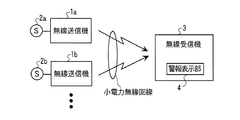
図1は本発明の実施形態の無線通信システムの構成を示す図である。
この無線通信システムは、複数台の無線送信機1a,1b,・・・と、1台の無線受信機3とからなる。
Embodiments of the present invention will be described below with reference to the drawings.
FIG. 1 is a diagram showing a configuration of a wireless communication system according to an embodiment of the present invention.
The wireless communication system includes a plurality of wireless transmitters 1 a, 1 b,... And a single wireless receiver 3.
無線送信機1a,1b,・・・には、火災センサ、ガス漏れセンサなどのような緊急事態を検知するセンサ2a,2b,・・・が接続されている。無線受信機3は警報表示部4を備えている。また、無線送信機1a,1b,・・・は無線受信機3からほぼ等距離の場所に配置されている。
無線送信機1a,1b,・・・と、無線受信機3とは、小電力無線回線により、無線送信機1a,1b,・・・が送信したデータを無線受信機3が受信可能である。ここで、無線送信機1a,1b,・・・、及び無線受信機3は小電力セキュリティシステムの規格に適合したものであって、1つの通信チャンネルが予め設定されており、その通信チャンネルを使用して無線送信機1a,1b,・・・から無線受信機3へのデータ送信を行う。 The radio transmitters 1a, 1b,... And the radio receiver 3 can receive the data transmitted by the radio transmitters 1a, 1b,. Here, the wireless transmitters 1a, 1b,... And the wireless receiver 3 conform to the standard of the low power security system, and one communication channel is set in advance, and the communication channel is used. Then, data transmission from the wireless transmitters 1a, 1b,... To the wireless receiver 3 is performed.
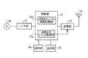
図2は無線送信機1aの構成を示すブロック図である。無線送信機1b等も同様に構成されている。無線送信機1aは、制御部11と、それぞれが制御部11に接続されたI/F(インタフェース)部12、送信部13、操作部14、及び表示部15を備えている。I/F部12にはセンサ2aが接続され、送信部13にはアンテナ16が接続されている。
FIG. 2 is a block diagram showing the configuration of the wireless transmitter 1a. The wireless transmitter 1b and the like are similarly configured. The wireless transmitter 1 a includes a
制御部11は、CPU、ROM、RAMなどを有するマイクロコンピュータから構成され、無線送信機1a全体の制御等を行う。制御部11は、送信部13からアンテナ16へ送出する小電力無線電波のレベル(強度)を制御する送信出力レベル制御部11aと、その送信出力レベルの制御に用いる情報を記憶するための送信出力レベル情報記憶部11bとを有する。また、図示されていないが、データの送信に使用する通信チャンネルの番号を記憶するためのチャンネル情報記憶部を有する。
The
操作部14は各種キーやスイッチからなり、ユーザがこの無線送信機1aを操作するときに使用される。表示部15はランプ等からなり、無線送信機1aの動作状態等を表示する。
The
図3は無線受信機3の構成を示すブロック図である。無線受信機3は、制御部31と、それぞれが制御部31に接続された受信部32、操作部33、表示部34、及び警報表示部4を備えている。受信部32にはアンテナ35が接続されている。
FIG. 3 is a block diagram showing the configuration of the wireless receiver 3. The wireless receiver 3 includes a
制御部31は、CPU、ROM、RAMなどを有するマイクロコンピュータから構成され、無線受信機3の全体の制御等を行う。また、図示されていないが、データの受信に使用する通信チャンネルの番号を記憶するためのチャンネル情報記憶部を有する。
The
受信部32は、アンテナ35で受信された小電力無線電波から通信データを分離し、制御部31へ送出する。操作部33は各種キーやスイッチからなり、ユーザがこの無線受信機3を操作するときに使用される。表示部34はLCD等からなり、無線受信機3の動作状態等を表示する。警報表示部4はランプ、スピーカ等からなり、火災警報、ガス漏れ警報等を報知する。表示部34が警報表示部4を兼用するように構成してもよい。
The receiving
以上のように構成された無線通信システムにおいて、無線送信機1a,1b,・・・のどれか一つに接続されているセンサ2a,2b,・・・が火災やガス漏れ等を検知し、検知信号を生成すると、その検知信号はI/F部12を通して制御部11へ送られる。制御部11は、受信した検知信号に基づいて小電力無線の通信データを作成し、送信部13へ出力する。このとき、制御部11内の送信レベル制御部11aは、送信レベル情報記憶部11bに記憶されている送信出力レベル制御情報(詳細は後述)を読み出し、それに基づいて送信部13に対し、送信出力レベル制御信号を出力する。送信部13は、制御部11から受け取った通信データを、制御部11から受け取った送信出力レベル制御信号に対応する送信出力レベルに増幅し、アンテナ16へ送出する。
In the wireless communication system configured as described above, the
無線受信機3では、無線送信機1a,1b,・・・のどれかから送信された通信データを載せた小電力無線電波がアンテナ35で受信され、受信部32で通信データが分離され、制御部31へ送られる。制御部31は通信データを解析し、その結果を警報表示部4にて報知するための信号を生成し、警報表示部4へ出力する。警報表示部4は、入力された信号に基づいて、火災やガス漏れ等の緊急事態の内容、及びそれを検知したセンサがどの無線送信機に接続されたものであるのかを示すランプの表示や音声の出力を行う。これにより、無線受信機3の周囲にいる人は、緊急事態の種類及びその発生場所を知ることができる。
In the wireless receiver 3, a low-power radio wave carrying communication data transmitted from one of the wireless transmitters 1a, 1b,... Is received by the
ここで、本実施形態の無線通信システムでは、無線送信機1a,1b,・・・に接続されているセンサ2a,2b,・・・のうち、複数のセンサが同時に検知信号を生成し、複数の無線送信機が同時に通信データを送信した結果、それらの送信電波が干渉することで、無線受信機がどの無線送信機の通信データも受信できなくなることを防止するため、複数の無線送信機1a,1b,・・・の送信出力レベルを以下のように制御している。
Here, in the wireless communication system of this embodiment, among the
図4は図1の無線通信システムの無線送信機の総数が2の場合の例であり、無線送信機1a,1bに接続されているセンサ2a,2bが同時に検知信号を生成しているときの送信出力レベル、及び無線受信機3の受信可能/不可能状態の時間的変化を示している。
FIG. 4 is an example when the total number of wireless transmitters of the wireless communication system of FIG. 1 is 2, and when the
センサ2a,2bが同時に検知信号を生成すると、図4に示すように、無線送信機1a,1bは、それぞれフレーム毎に同じ通信データを生成し、センサ2a,2bが検知信号を生成している間、繰り返し送信する。ここでは、フレーム番号F1〜F8までを図示した。
When the
この繰り返し送信動作の間、無線送信機1aの送信部13の送信出力レベルは、法規制範囲内の最大レベルHに設定する。一方、無線送信機1bの送信出力レベルは、先頭の送信フレームF1で最大レベルHに設定し、第2〜第3送信フレームで送信出力レベルをL(例えばHの60%)に低下させ、以後2個の送信フレーム毎に交互にレベルH及びLに設定している。
During this repeated transmission operation, the transmission output level of the
この結果、無線受信機3では、無線送信機1a,1bの双方の送信出力レベルがHの送信フレーム(F1,F4,F5等)では、双方の送信電波が干渉するため、いずれの通信データも受信できないが(図の×)、無線送信機1bの送信出力レベルがLの送信フレーム(F2,F3,F6,F7)では、無線送信機1aからの送信出力レベルの方が高いため、双方の送信電波は干渉せず、無線送信機1aから送信された通信データを受信することができる(図の○)。従って、無線送信機1aに接続されているセンサ2aの検知対象を最も緊急性の高い緊急事態(例:火災)に設定しておけば、その緊急事態を確実に検知することができる。
As a result, in the wireless receiver 3, in the transmission frames (F1, F4, F5, etc.) in which the transmission output levels of both the wireless transmitters 1a and 1b are H, both transmission radio waves interfere with each other. In the transmission frame (F2, F3, F6, F7) in which the transmission output level of the wireless transmitter 1b is L, the transmission output level from the wireless transmitter 1a is higher. The transmission radio wave does not interfere, and communication data transmitted from the wireless transmitter 1a can be received (◯ in the figure). Therefore, if the detection target of the
図5は、図4における無線送信機1bの送信フレームのタイミングが1フレーム期間の略半分遅れた場合を示す。この場合、無線受信機3はフレーム番号F3,F7の通信フレームデータを受信することができる。 FIG. 5 shows a case where the transmission frame timing of the wireless transmitter 1b in FIG. 4 is delayed by approximately half of one frame period. In this case, the wireless receiver 3 can receive the communication frame data of the frame numbers F3 and F7.
図6は図1の無線通信システムの無線送信機の総数が3の場合の例であり、無線送信機1a,1b,1c(1cは図示せず)に接続されているセンサ2a,2b,2c(2cは図示せず)が同時に検知信号を生成しているときの送信出力レベル、及び無線受信機3の受信可能/不可能状態の時間的変化を示している。
FIG. 6 shows an example in which the total number of wireless transmitters in the wireless communication system of FIG. 1 is 3, and
センサ2a,2b,2cが同時に検知信号を生成すると、図6に示すように、無線送信機1a,1b,1cは、それぞれフレーム毎に同じ通信データを生成し、センサ2a,2b,2cが検知信号を生成している間、繰り返し送信する。ここでは、フレーム番号F1〜F15までを図示した。
When the
この繰り返し送信動作の間、無線送信機1aの送信部13の送信出力レベルは、法規制範囲内の最大レベルHの一定値に設定される。一方、無線送信機1bの送信出力レベルは、先頭の送信フレームF1で最大レベルHに設定し、第2〜第5送信フレームで送信出力レベルをLに低下させ、以後は1個の送信フレームをHに設定した後に4個の送信フレームをLに設定する動作を繰り返す。また、無線送信機1cの送信出力レベルは、先頭の送信フレームF1で最大レベルHに設定し、第2〜第7送信フレームで送信出力レベルをLに低下させ、以後は1個の送信フレームをHに設定した後に6個の送信フレームをLに設定する動作を繰り返す。
During this repeated transmission operation, the transmission output level of the
この結果、無線受信機3では、無線送信機1b又は1cの少なくとも一方の送信出力レベルがHの送信フレーム(F1,F6,F8,F11、F15等)においては、無線送信機1aと1b又は1cの送信電波が干渉し、いずれの通信データも受信できないが(図の×)、無線送信機1b及び1cの送信出力レベルがLの送信フレーム(F2〜F5,F7,F9〜F10、F12〜F14)では、送信電波が干渉しないため、無線送信機1aから送信された通信データを受信できる(図の○)。 As a result, in the wireless receiver 3, in the transmission frames (F1, F6, F8, F11, F15, etc.) in which the transmission output level of at least one of the wireless transmitters 1b or 1c is H, the wireless transmitters 1a and 1b or 1c The transmission radio waves interfere with each other and cannot receive any communication data (X in the figure), but the transmission frames (F2 to F5, F7, F9 to F10, F12 to F14) with the transmission output level of the wireless transmitters 1b and 1c are L. ), Since transmission radio waves do not interfere, communication data transmitted from the wireless transmitter 1a can be received (◯ in the figure).
図7は、図6における無線送信機1b及び1cの送信フレームのタイミングがそれぞれ1フレーム期間の略半分及び3個半遅れた場合を示す。この場合、無線受信機3はフレーム番号F5,F8〜F9、F13〜F15の通信データを受信することができる。 FIG. 7 shows a case where the transmission frame timings of the wireless transmitters 1b and 1c in FIG. 6 are delayed by approximately half and three and a half of one frame period, respectively. In this case, the wireless receiver 3 can receive the communication data of the frame numbers F5, F8 to F9, and F13 to F15.
図8は、図1の無線通信システムの無線送信機の総数が3の場合であり、無線送信機1a,1b,1cに接続されているセンサ2a,2b,2cが同時に検知信号を生成しているときの送信出力レベル、及び無線受信機3の受信可能/不可能状態の時間的変化の別の例である。
FIG. 8 shows a case where the total number of wireless transmitters in the wireless communication system of FIG. 1 is 3, and the
この図において、無線送信機1aの送信出力レベルの時間的変化は図6と同じである。一方、無線送信機1b,1cについては、図6の先頭フレームのレベルHを削除するとともに、1フレーム進めたものと言える。つまり、無線送信機1bでは、4フレームをレベルLにした後に次の1フレームをレベルHにする動作を繰り返し、無線送信機1cでは、6フレームをレベルLにした後に次の1フレームをレベルHにする動作をそれぞれの先頭の送信フレームから繰り返す。 In this figure, the temporal change in the transmission output level of the wireless transmitter 1a is the same as in FIG. On the other hand, for the wireless transmitters 1b and 1c, it can be said that the level H of the first frame in FIG. 6 is deleted and one frame is advanced. That is, the wireless transmitter 1b repeats the operation of setting 4 frames to level L and then setting the next frame to level H, and the wireless transmitter 1c sets 6 frames to level L and then setting the next frame to level H. Is repeated from the first transmission frame.
この結果、無線受信機3では、無線送信機1b及び1cの送信出力レベルがLの送信フレーム(F1〜F4,F6,F8〜F9、F11〜F13)で、無線送信機1aから送信された通信データを受信できる(図の○)。つまり、図6よりも1フレーム期間早いタイミングで受信できることになるから、より早く警報を発することができる。 As a result, in the wireless receiver 3, the transmissions transmitted from the wireless transmitter 1a in the transmission frames (F1 to F4, F6, F8 to F9, F11 to F13) whose transmission output levels of the wireless transmitters 1b and 1c are L are shown. Data can be received (○ in the figure). That is, since it can be received at a timing earlier than that of FIG. 6 by one frame period, an alarm can be issued earlier.
次に、図1の無線通信システムを構成する無線送信機が1a,1b,1cの3台であり、かつ無線送信機1b,1cの送信出力レベルをH、M、Lの3段階に変化させる場合について説明する。ここで、Hは法規制範囲内の最大レベル、M、Lは例えばそれぞれHの80%、60%である。また、図6〜図8では、3台の無線送信機が1a,1b,1cに接続されているセンサ2a,2b,2cが同時に検知信号を生成しているときの動作を示したが、以下の動作例ではセンサ2a,2b,2cのうち検知信号を生成していないセンサがある場合についても説明する。
Next, there are three wireless transmitters 1a, 1b, and 1c constituting the wireless communication system in FIG. 1, and the transmission output levels of the wireless transmitters 1b and 1c are changed in three stages of H, M, and L. The case will be described. Here, H is the maximum level within the legal regulation range, and M and L are, for example, 80% and 60% of H, respectively. 6 to 8 show the operation when the
図9に示すように、3台の無線送信機1a,1b,1cのそれぞれがセンサ2a,2b,2cの検知信号に応じてデータ送信を行う組み合わせのパターンは7通りである。この図において、○はデータ送信を行っている状態を示し、×は行っていない状態を示す。
As shown in FIG. 9, there are seven combinations of patterns in which each of the three wireless transmitters 1a, 1b, and 1c transmits data according to the detection signals of the
この図のパターンP1は3台の無線送信機が1a,1b,1cがデータ送信を行うパターン、P2〜P4は3台のうち2台の無線送信機がデータ送信を行うパターン、P5〜P7は1台の無線送信機のみがデータ送信を行うパターンである。これらのパターンのうち、パターンP5〜P7では電波干渉は起こらないため、無線送信機から送信されたデータは確実に無線受信機3で受信される。従って、以下、パターンP1〜P4の場合について説明する。 The pattern P1 in this figure is a pattern in which three wireless transmitters 1a, 1b, and 1c transmit data, P2 to P4 are patterns in which two of the three wireless transmitters transmit data, and P5 to P7 are In this pattern, only one wireless transmitter transmits data. Among these patterns, radio wave interference does not occur in the patterns P5 to P7, and therefore the data transmitted from the wireless transmitter is reliably received by the wireless receiver 3. Accordingly, the case of the patterns P1 to P4 will be described below.
図10〜図13は、無線送信機が1a,1b,1cそれぞれパターンP1〜P4で動作する場合の無線送信機1a,1b,1cの送信出力レベル、及び無線受信機3の受信可能/不可能状態の時間的変化を示している。 10 to 13 show the transmission output levels of the wireless transmitters 1a, 1b, and 1c when the wireless transmitter operates in the patterns P1 to P4 1a, 1b, and 1c, respectively, and whether or not the wireless receiver 3 can receive signals. It shows the time change of the state.
このように無線送信機1b,1cのレベルを3段階に変化させると、図13に示されているパターンP4、即ち送信出力レベルが常時Hである無線送信機1aがデータ送信を行わないときに、2段階に変化させた場合と比べて、無線受信機3がデータを受信できるフレーム数が増えることになる。 When the levels of the wireless transmitters 1b and 1c are changed in three stages in this way, the pattern P4 shown in FIG. 13, that is, when the wireless transmitter 1a whose transmission output level is always H does not perform data transmission. Compared with the case where the level is changed in two steps, the number of frames in which the wireless receiver 3 can receive data increases.
以上のように、本発明の実施形態の通信システムによれば、無線受信機3から等距離に配置されている複数の無線送信機1a,1b等がそれぞれのセンサ2a,2b等の検知信号に基づいて、同時に通信データを連続送信した場合でも、無線受信機3は、そのうち1台の無線送信機から送信された通信データを確実に受信することができるため、警報動作の即応性及び確実性が向上する。
As described above, according to the communication system of the embodiment of the present invention, a plurality of wireless transmitters 1a, 1b, etc. arranged at equal distances from the wireless receiver 3 are used as detection signals of the
なお、以上の説明では、無線受信機3にて警報表示を行っているが、無線受信機3を電話回線で警備センタに接続し、その警備センタにも通報するように構成してもよい。 In the above description, the wireless receiver 3 displays an alarm. However, the wireless receiver 3 may be connected to a security center via a telephone line and notified to the security center.
1a,1b・・・無線送信機、3・・・無線受信機、4・・・警報表示部、11・・・制御部、13・・・送信部。 DESCRIPTION OF SYMBOLS 1a, 1b ... Wireless transmitter, 3 ... Wireless receiver, 4 ... Alarm display part, 11 ... Control part, 13 ... Transmission part.
Claims (3)
一の無線送信機は前記データの送信出力レベルを前記所定時間所定のレベルになるように制御する第1の送信レベル制御手段を有し、他の無線送信機は前記データの送信出力レベルを前記所定時間内で一時的に前記所定のレベルより低いレベルになるように制御する第2の送信レベル制御手段を有することを特徴とする無線通信システム。 A wireless communication system having a plurality of wireless transmitters each continuously transmitting data for a predetermined time using the same communication channel, and a wireless receiver for receiving data transmitted from the wireless transmitter,
One wireless transmitter has first transmission level control means for controlling the transmission output level of the data to be a predetermined level for the predetermined time, and the other wireless transmitter sets the transmission output level of the data to the data transmission level. A wireless communication system comprising: a second transmission level control means for controlling to temporarily become lower than the predetermined level within a predetermined time.
前記第2の送信レベル制御手段は、前記所定時間内で周期的に送信出力レベルを変化させることを特徴とする無線通信システム。 The wireless communication system according to claim 1, wherein
The wireless communication system, wherein the second transmission level control means changes the transmission output level periodically within the predetermined time.
前記第2の送信レベル制御手段は、前記所定時間の先頭にて前記所定のレベルより低いレベルになるように制御することを特徴とする無線通信システム。 The wireless communication system according to claim 1, wherein
The wireless communication system, wherein the second transmission level control means performs control so as to become a level lower than the predetermined level at the beginning of the predetermined time.
Priority Applications (1)
| Application Number | Priority Date | Filing Date | Title |
|---|---|---|---|
| JP2007241772A JP4919073B2 (en) | 2007-09-19 | 2007-09-19 | Wireless communication system |
Applications Claiming Priority (1)
| Application Number | Priority Date | Filing Date | Title |
|---|---|---|---|
| JP2007241772A JP4919073B2 (en) | 2007-09-19 | 2007-09-19 | Wireless communication system |
Publications (2)
| Publication Number | Publication Date |
|---|---|
| JP2009077000A JP2009077000A (en) | 2009-04-09 |
| JP4919073B2 true JP4919073B2 (en) | 2012-04-18 |
Family
ID=40611585
Family Applications (1)
| Application Number | Title | Priority Date | Filing Date |
|---|---|---|---|
| JP2007241772A Active JP4919073B2 (en) | 2007-09-19 | 2007-09-19 | Wireless communication system |
Country Status (1)
| Country | Link |
|---|---|
| JP (1) | JP4919073B2 (en) |
Families Citing this family (1)
| Publication number | Priority date | Publication date | Assignee | Title |
|---|---|---|---|---|
| JP5893835B2 (en) * | 2011-03-10 | 2016-03-23 | ホーチキ株式会社 | Alarm and monitoring system |
Family Cites Families (4)
| Publication number | Priority date | Publication date | Assignee | Title |
|---|---|---|---|---|
| JPS60225998A (en) * | 1984-04-24 | 1985-11-11 | 三菱電機株式会社 | Home security sensor transmission system |
| JPH04356825A (en) * | 1991-03-27 | 1992-12-10 | Matsushita Electric Works Ltd | Radio equipment |
| JPH05143882A (en) * | 1991-11-19 | 1993-06-11 | Sekisui Chem Co Ltd | Wireless security system |
| JPH1079683A (en) * | 1996-09-03 | 1998-03-24 | Anritsu Corp | Radio equipment with gain changeover antenna |
-
2007
- 2007-09-19 JP JP2007241772A patent/JP4919073B2/en active Active
Also Published As
| Publication number | Publication date |
|---|---|
| JP2009077000A (en) | 2009-04-09 |
Similar Documents
| Publication | Publication Date | Title |
|---|---|---|
| US8553664B2 (en) | Field optimized, configurable wireless fire system | |
| US9204465B2 (en) | Wireless communication system and wireless communication device | |
| EP2830279B1 (en) | Interference avoidance technique for wireless networks used in critical applications | |
| HK1080637A1 (en) | Method of controlling operation of at least one transmitter and/or one receiver, communication system and use of such a method or such a system | |
| JP2008004033A (en) | Wireless residential fire alarm, wireless residential fire alarm system | |
| WO2008042526A2 (en) | Method and device for increasing capacity of tdd wireless communication systems | |
| KR20160012773A (en) | Power Saving Helmet for Radio Communication and transmitting/receiving method thereof | |
| WO2010147403A3 (en) | Method for transmitting packet downlink ack/nack information in a wireless communication system and apparatus for the same | |
| KR20090019860A (en) | Mobile station device, base station device, and paging method | |
| JP5984108B2 (en) | Transfer device and fire alarm linkage system | |
| JP4803130B2 (en) | Wireless communication system | |
| JP2009230406A (en) | Wireless transmission system | |
| JP4919073B2 (en) | Wireless communication system | |
| EP1885072B1 (en) | Method and system for visual indication of the function of wireless receivers and a wireless receiver. | |
| CN101124781A (en) | Synchronized wireless communications system | |
| JP2011066530A (en) | Radio communication system | |
| JP2006223677A (en) | Control system for electric appliance and gas appliance | |
| EP1334574A1 (en) | Method and apparatus to synchronize mobile radios | |
| JP5838374B2 (en) | Wireless communication system | |
| JP4965918B2 (en) | Fire alarm system | |
| KR101572779B1 (en) | Radio walkie-talkie having function for emergency call and radio paging system and the method therefor | |
| JP2009217592A (en) | Radio system | |
| JP4679476B2 (en) | Wireless communication device | |
| JP5369060B2 (en) | Fire alarm system | |
| KR20170025015A (en) | An apparatus and method for performing wireless charging in vehicle |
Legal Events
| Date | Code | Title | Description |
|---|---|---|---|
| A621 | Written request for application examination |
Free format text: JAPANESE INTERMEDIATE CODE: A621 Effective date: 20100611 |
|
| A977 | Report on retrieval |
Free format text: JAPANESE INTERMEDIATE CODE: A971007 Effective date: 20111222 |
|
| TRDD | Decision of grant or rejection written | ||
| A01 | Written decision to grant a patent or to grant a registration (utility model) |
Free format text: JAPANESE INTERMEDIATE CODE: A01 Effective date: 20120105 |
|
| A01 | Written decision to grant a patent or to grant a registration (utility model) |
Free format text: JAPANESE INTERMEDIATE CODE: A01 |
|
| A61 | First payment of annual fees (during grant procedure) |
Free format text: JAPANESE INTERMEDIATE CODE: A61 Effective date: 20120118 |
|
| R150 | Certificate of patent or registration of utility model |
Ref document number: 4919073 Country of ref document: JP Free format text: JAPANESE INTERMEDIATE CODE: R150 Free format text: JAPANESE INTERMEDIATE CODE: R150 |
|
| FPAY | Renewal fee payment (event date is renewal date of database) |
Free format text: PAYMENT UNTIL: 20150210 Year of fee payment: 3 |