JP4917543B2 - Method for operating a computer device - Google Patents
Method for operating a computer device Download PDFInfo
- Publication number
- JP4917543B2 JP4917543B2 JP2007541990A JP2007541990A JP4917543B2 JP 4917543 B2 JP4917543 B2 JP 4917543B2 JP 2007541990 A JP2007541990 A JP 2007541990A JP 2007541990 A JP2007541990 A JP 2007541990A JP 4917543 B2 JP4917543 B2 JP 4917543B2
- Authority
- JP
- Japan
- Prior art keywords
- component
- program code
- computer
- channel
- components
- Prior art date
- Legal status (The legal status is an assumption and is not a legal conclusion. Google has not performed a legal analysis and makes no representation as to the accuracy of the status listed.)
- Expired - Fee Related
Links
Images
Classifications
-
- G—PHYSICS
- G06—COMPUTING OR CALCULATING; COUNTING
- G06F—ELECTRIC DIGITAL DATA PROCESSING
- G06F8/00—Arrangements for software engineering
- G06F8/30—Creation or generation of source code
- G06F8/35—Creation or generation of source code model driven
-
- F—MECHANICAL ENGINEERING; LIGHTING; HEATING; WEAPONS; BLASTING
- F02—COMBUSTION ENGINES; HOT-GAS OR COMBUSTION-PRODUCT ENGINE PLANTS
- F02D—CONTROLLING COMBUSTION ENGINES
- F02D41/00—Electrical control of supply of combustible mixture or its constituents
- F02D41/24—Electrical control of supply of combustible mixture or its constituents characterised by the use of digital means
- F02D41/26—Electrical control of supply of combustible mixture or its constituents characterised by the use of digital means using computer, e.g. microprocessor
-
- G—PHYSICS
- G06—COMPUTING OR CALCULATING; COUNTING
- G06F—ELECTRIC DIGITAL DATA PROCESSING
- G06F9/00—Arrangements for program control, e.g. control units
- G06F9/06—Arrangements for program control, e.g. control units using stored programs, i.e. using an internal store of processing equipment to receive or retain programs
- G06F9/44—Arrangements for executing specific programs
- G06F9/448—Execution paradigms, e.g. implementations of programming paradigms
- G06F9/4482—Procedural
- G06F9/4484—Executing subprograms
Landscapes
- Engineering & Computer Science (AREA)
- Software Systems (AREA)
- General Engineering & Computer Science (AREA)
- Theoretical Computer Science (AREA)
- Physics & Mathematics (AREA)
- General Physics & Mathematics (AREA)
- Computer Hardware Design (AREA)
- Microelectronics & Electronic Packaging (AREA)
- Chemical & Material Sciences (AREA)
- Combustion & Propulsion (AREA)
- Mechanical Engineering (AREA)
- Stored Programmes (AREA)
Description
本発明は、請求項1の前提項に記載されているコンピュータ装置を作動させる方法、これに対応するコンピュータプログラム、ならびにコンピュータプログラム製品に関するものである。 The present invention relates to a method for operating a computer device as set forth in the premise of claim 1, a computer program corresponding thereto, and a computer program product.
以下においては、自動車用の調節・制御アルゴリズムを主に取りあげて説明するが、本発明による方法は、そのような用途に限定されるものではない。 In the following, adjustment and control algorithms for automobiles will be mainly described and explained, but the method according to the present invention is not limited to such applications.
自動車用の調節アルゴリズム及び/又は制御アルゴリズムの機能モデルは、通常、階層的に構造化されている。開発あるいはモデリングの間に、各コンポーネントが段階的に組み合わされて機能となる。このときコンポーネントは、明示インターフェース(Interfaces)を提供することによって、外部から内部のデータまたは信号へのアクセスを制限する。他のコンポーネントのインターフェースへのアクセスも、インターフェース記述によって明示的に設定される。 The functional model of the regulation and / or control algorithm for automobiles is usually structured hierarchically. During development or modeling, each component is combined in stages to become a function. At this time, the component restricts access to internal data or signals from the outside by providing an explicit interface (Interfaces). Access to other component interfaces is also explicitly set by the interface description.
車両全体は、複数の機能からなる階層を含むことができる。1つの機能は、複数のコンポーネントからなる階層を含んでいる。 The entire vehicle can include a hierarchy of multiple functions. One function includes a hierarchy of a plurality of components.
コンポーネントと機能の間での信号やデータのやり取りも、同じく、ポートと呼ばれるインターフェースを介して行われる。以下に詳しく説明するコンポーネントでは、このようなポートを介して、周辺環境の物理的または物質的な性質に影響を与えることができるアクチュエータや、周辺環境の性質を把握することができるセンサが制御される。 Similarly, exchange of signals and data between components and functions is performed via an interface called a port. The components detailed below control actuators that can affect the physical or material properties of the surrounding environment and sensors that can understand the properties of the surrounding environment through such ports. The
このような形で統合されたモデルを見通しの良い状態に保つために、センサ通信およびアクチュエータ通信の可視性が、局所的に制限される(局所性原則)。センサ信号またはアクチュエータ信号が1つのコンポーネントによってのみ必要とされるとき、その信号の可視性は、当該コンポーネントだけに制限される。 In order to keep the model integrated in this way in line of sight, the visibility of sensor and actuator communication is locally limited (locality principle). When a sensor signal or actuator signal is only needed by one component, the visibility of that signal is limited to that component only.
局所的に可視的なセンサ信号またはアクチュエータ信号をカプセル化するコンポーネントは、センサコンポーネントまたはアクチュエータコンポーネントと呼ばれる。それ以外のコンポーネントは、リーフコンポーネントと呼ばれるのが普通である。機能全体のセンサ信号またはアクチュエータ信号は、1つの機能内でのみ可視的であるのに対して、最上位の階層レベルにある車両全体のセンサ信号またはアクチュエータ信号は、どの機能からでも可視的である。 A component that encapsulates a locally visible sensor or actuator signal is called a sensor component or actuator component. The other components are usually called leaf components. A sensor or actuator signal for the entire function is only visible within one function, whereas a sensor or actuator signal for the entire vehicle at the highest hierarchical level is visible from any function .
局所性原則は、センサコンポーネントまたはアクチュエータコンポーネントをそれぞれの階層レベルに配置し、読み出しまたは書き込みをするコンポーネントにインターフェースを設置することによって具体化される。このような手順により、機能レベルと車両レベルでインターフェースの数が大幅に減り、センサコンポーネントとアクチュエータコンポーネントの機能的なカプセル化が実現される。 The principle of locality is embodied by placing sensor components or actuator components at respective hierarchical levels and placing an interface on the component that reads or writes. Such a procedure significantly reduces the number of interfaces at the functional level and the vehicle level and realizes functional encapsulation of the sensor and actuator components.
例えばラピッドプロトタイピングシステム(RP)や電子制御ユニット(ECU)などの試作用ハードウェアでは、上述した規則に基づいてモデル化された機能を実行すると、この局所性原則への違反が生じる。 For example, in prototype hardware such as a rapid prototyping system (RP) or an electronic control unit (ECU), a violation of the locality principle occurs when a function modeled based on the rules described above is executed.
試作用ハードウェアに対応する1セットのセンサコンポーネントおよびアクチュエータコンポーネントを、モデルに組み込むことが必要である。プラットフォーム・ソフトウェアコンポーネントと呼ばれるこのようなセンサコンポーネントおよびアクチュエータコンポーネントのモデル内部での記述は、たとえばECUのマイクロコントローラにおける周辺機器モジュールや、RPシステムにおける出入力カードといった試作用ハードウェアの実際の条件を基準としている。 It is necessary to incorporate a set of sensor and actuator components corresponding to the prototype hardware into the model. The descriptions of such sensor components and actuator components, called platform software components, are based on the actual conditions of prototype hardware such as peripheral modules in ECU microcontrollers and I / O cards in RP systems. It is said.
こうしたプラットフォーム・ソフトウェアコンポーネントは、相応のハードウェアモジュールの正確な数の信号を、入力または出力として供給する。今日のモデリングツールでは、こうしたコンポーネントおよびこれに伴うすべての出入力は、最上位の階層レベルで定義されており、そのためにシステム全体で可視的となっている。このことは、機能階層またはコンポーネント階層のリーフコンポーネント内部で、個々の信号を局所的に利用することを妨げる。 Such platform software components provide the exact number of signals of the corresponding hardware modules as inputs or outputs. In today's modeling tools, these components and all their inputs and outputs are defined at the highest hierarchical level and are therefore visible throughout the system. This prevents local use of individual signals within the leaf components of the functional hierarchy or component hierarchy.
その結果、上に説明した局所性原則に違反する、見通しの良くないモデルが生じることになる。 The result is an unsightly model that violates the locality principle described above.
以上のような背景のもとで、本発明により、それぞれ独立請求項に記載されたコンピュータ装置を作動させる方法ならびにこれに対応するコンピュータプログラム、およびコンピュータプログラム製品が提案される。有利な実施形態は、それぞれの従属請求項および以下の説明から明らかである。 Under the background as described above, according to the present invention, a method of operating a computer apparatus described in each independent claim, a computer program corresponding to the method, and a computer program product are proposed. Advantageous embodiments are evident from the respective dependent claims and the following description.
第1のコンピュータ装置を作動させる本発明の方法では、コンポーネントが階層的に組み合わされてなる機能が階層的に組み合わされて構成される機能モデルを含むソースプログラムコードが作成される。機能モデル内部におけるコンポーネントの可視性は、階層によって規定され、特定のコンポーネントについて階層内部でワイルドカードが利用される。実行可能なプログラムコードが生成され、ワイルドカードは、相応に作成されたマッピング規則により、実行可能なプログラムコードの作成前に特定のコンポーネントで置き換えられる。このようなマッピング規則を導入することで、局所性原則を維持することができる。 In the method of the present invention for operating the first computer device, source program code including a function model configured by hierarchically combining functions obtained by hierarchically combining components is created. The visibility of components within the functional model is defined by hierarchy, and wildcards are used within the hierarchy for specific components. Executable program code is generated and wildcards are replaced with specific components prior to creation of the executable program code by correspondingly created mapping rules. By introducing such mapping rules, the locality principle can be maintained.
本発明の方法では、実行可能なプログラムコードは第2のコンピュータ装置で生成され、第1のコンピュータ装置へ伝送されるのが好ましい。第2のコンピュータ装置としては、例えば従来型のコンピュータを使用することができる。 In the method of the present invention, the executable program code is preferably generated by the second computer device and transmitted to the first computer device. For example, a conventional computer can be used as the second computer device.
センサコンポーネント及び/又はアクチュエータコンポーネントがコンポーネントとして、および特にワイルドカードとして利用される本発明の方法が、格別に好ましい。 The method of the present invention in which sensor components and / or actuator components are utilized as components and in particular as wildcards is particularly preferred.
本発明による方法の有利な実施形態では、機能モデルは、自動車用の調節アルゴリズム及び/又は制御アルゴリズムである。とりわけ自動車製造業では、局所性原理への違反を引き起こすような、調節アルゴリズム及び/又は制御アルゴリズムを実行するためのコンピュータ装置の使用方法が、しばしば見られる。本発明による方法の有利な適用は、機能モデルのより良い見通しを提供する。 In an advantageous embodiment of the method according to the invention, the functional model is a regulation algorithm and / or a control algorithm for a motor vehicle. Especially in the automobile manufacturing industry, there are often found uses of computer devices to execute regulation and / or control algorithms that cause violations of the locality principle. The advantageous application of the method according to the invention provides a better perspective of the functional model.
本発明の方法において、第1のコンピュータ装置として、試作用ハードウェア、特にラピッドプロトタイピングシステムや電子制御ユニットが使用されるのが好ましい。このような使用は、試作用ハードウェアの機能モデルを作成するときに、局所性原則の好ましい維持を可能にする。 In the method of the present invention, it is preferable to use prototype hardware, particularly a rapid prototyping system or an electronic control unit, as the first computer device. Such use allows the preferred maintenance of the locality principle when creating a prototype hardware functional model.
本発明の方法においてマッピング規則は、各コンポーネントがワイルドカードに割り当てられるリスト形式の構造に存在しているのが格別に好ましい。 In the method of the present invention, it is particularly preferable that the mapping rules exist in a list-type structure in which each component is assigned to a wild card.
本発明において、マッピング規則は、各コンポーネントがワイルドカードに割り当てられるグラフィック表示として存在しているのが同じく好ましい。 In the present invention, it is also preferred that the mapping rules exist as a graphical display in which each component is assigned to a wildcard.
マッピング規則のこれら両方の実施形態は、格別に簡単なやり方で取り扱うことができる。 Both these embodiments of mapping rules can be handled in a particularly simple manner.
特定のコンポーネントについて階層内部でワイルドカードが使用されていない別の機能モデルからソースプログラムコードの機能モデルが生成されて、マッピング規則が作成される本発明の方法が格別に好ましい。このことは、既に作成ずみのモデルについて、本発明による方法を有利に適用することを可能にする。 The method of the present invention is particularly preferred in which a mapping program is created by generating a functional model of the source program code from another functional model that does not use wildcards within the hierarchy for a particular component. This makes it possible to advantageously apply the method according to the invention to already created models.
プログラムコード手段を備える本発明のコンピュータプログラムは、このコンピュータプログラムがコンピュータまたは相応の計算ユニットで実行されるときに、本発明による方法のマッピング規則を実行及び/又は作成するように設計されている。 The computer program according to the invention with program code means is designed to execute and / or create the mapping rules of the method according to the invention when the computer program is executed on a computer or a corresponding computing unit.
コンピュータで読取り可能なデータ媒体に保存されたプログラムコード手段を備える本発明のコンピュータプログラム製品は、このコンピュータプログラムがコンピュータまたは相応の計算ユニット、特に本発明による装置で実行されるときに、本発明による方法のマッピング規則を実行及び/又は作成することが意図されている。 A computer program product according to the invention comprising program code means stored in a computer readable data medium is according to the invention when the computer program is executed on a computer or a corresponding computing unit, in particular an apparatus according to the invention. It is intended to implement and / or create method mapping rules.
本発明の上記以外の利点や実施形態は、明細書および添付の図面から明らかである。 Other advantages and embodiments of the present invention will be apparent from the specification and the accompanying drawings.
上に述べた構成要件および以下に説明する構成要件は、そのつど記載されている組み合わせのかたちだけでなく、それ以外の組み合わせや単独のかたちでも、本発明の枠組から外れることなく適用可能であるのは言うまでもない。 The constituent requirements described above and the constituent requirements described below can be applied not only in the combinations described above but also in other combinations or in a single form without departing from the framework of the present invention. Needless to say.
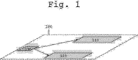
図1には、全体として符号100が付された機能が図示されている。機能の最上位の階層レベルが示されている。機能100は、第1のサブ機能110と第2のサブ機能120を有している。さらにこの機能は、両方のサブ機能110および120にセンサ信号を提供するセンサコンポーネント130を有している。 FIG. 1 shows a function denoted by reference numeral 100 as a whole. The top hierarchical level of the function is shown. The function 100 has a first sub function 110 and a second sub function 120. This function further includes a sensor component 130 that provides sensor signals to both sub-functions 110 and 120.
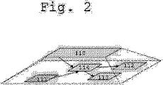
図2は、サブ機能110の各コンポーネントからなる階層を示している。最上位の階層レベルに符号110が付されている。サブ機能110は、局所的なセンサコンポーネント111と、2つの局所的なアクチュエータコンポーネント112,113とを有している。さらにサブ機能はリーフコンポーネント114を有している。リーフコンポーネント114は、局所的なセンサコンポーネント111の値を機能全体のセンサコンポーネント130の信号と関連づけて、局所的なアクチュエータコンポーネント112,113を調節するために計算結果を利用する計算コンポーネントとして製作されている。 FIG. 2 shows a hierarchy composed of each component of the sub function 110. Reference numeral 110 is assigned to the highest hierarchical level. The sub-function 110 has a local sensor component 111 and two local actuator components 112 and 113. In addition, the sub-function has a leaf component 114. The leaf component 114 is fabricated as a computational component that correlates the value of the local sensor component 111 with the signal of the overall functional sensor component 130 and uses the computational results to adjust the local actuator components 112, 113. Yes.
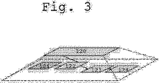
図3は、サブ機能120のコンポーネントからなる階層を示している。最上位の階層レベルに、符号120が付されている。サブ機能120は、局所的なセンサコンポーネント121と、2つの局所的なリーフコンポーネント122,123と、局所的なアクチュエータコンポーネント124とを有している。 FIG. 3 shows a hierarchy composed of components of the sub function 120. Reference numeral 120 is assigned to the highest hierarchical level. The sub-function 120 has a local sensor component 121, two local leaf components 122, 123 and a local actuator component 124.
リーフコンポーネント122は、局所的なセンサコンポーネント121の値を機能全体のセンサコンポーネント130の信号と関連づけて、計算結果を次のリーフコンポーネント123に送る計算コンポーネントとして製作されている。リーフコンポーネント123は、例えば同じく計算を実行し、その結果を局所的なアクチュエータコンポーネント124の調節のために利用する。 The leaf component 122 is manufactured as a calculation component that associates the value of the local sensor component 121 with the signal of the sensor component 130 of the entire function and sends the calculation result to the next leaf component 123. The leaf component 123 also performs calculations, for example, and uses the results for local actuator component 124 adjustment.
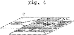
図4は、機能100の2つの階層レベルを示している。機能100は、第1のサブ機能110と第2のサブ機能120を有している。さらにこの機能は、両方のサブ機能110および120にセンサ信号を提供するセンサコンポーネント130を有している。 FIG. 4 shows two hierarchical levels of function 100. The function 100 has a first sub function 110 and a second sub function 120. This function further includes a sensor component 130 that provides sensor signals to both sub-functions 110 and 120.
サブ機能110は、局所的なセンサコンポーネント111と、2つの局所的なアクチュエータコンポーネント112,113と、局所的なセンサコンポーネント111の値を機能全体のセンサコンポーネント130の信号と関連づけて、局所的なアクチュエータコンポーネント112,113を調節するために計算結果を利用するリーフコンポーネント114とを有している。センサコンポーネント111とアクチュエータコンポーネント112,113は、サブ機能110の内部で機能的にカプセル化されている。 The sub-function 110 associates the value of the local sensor component 111, the two local actuator components 112, 113, and the local sensor component 111 with the signal of the sensor component 130 of the entire function, And a leaf component 114 that uses the calculation results to adjust the components 112, 113. The sensor component 111 and the actuator components 112 and 113 are functionally encapsulated inside the sub-function 110.
サブ機能120は、局所的なセンサコンポーネント121と、両方の局所的なリーフコンポーネント122,123と、局所的なアクチュエータコンポーネント124とを有している。 The sub-function 120 has a local sensor component 121, both local leaf components 122, 123 and a local actuator component 124.
リーフコンポーネント122は、局所的なセンサコンポーネント121の値を機能全体のセンサコンポーネント130の信号と関連づけて、計算結果を次のリーフコンポーネント123に送り、このリーフコンポーネントは、例えば同じく計算を実行し、その結果を局所的なアクチュエータコンポーネント124の調節のために利用する。センサコンポーネント121とアクチュエータコンポーネント124は、サブ機能120の内部で機能的にカプセル化されている。 The leaf component 122 associates the value of the local sensor component 121 with the signal of the sensor sensor 130 of the entire function and sends the calculation result to the next leaf component 123, which also performs the calculation, for example, The result is used for local actuator component 124 adjustment. Sensor component 121 and actuator component 124 are functionally encapsulated within sub-function 120.
図1から図4は、図示されている機能100とそのサブ機能110,120について考えられる、階層レベル内部のさまざまな図面を示している。 FIGS. 1-4 show various views within the hierarchy levels that may be considered for the illustrated function 100 and its sub-functions 110,120.
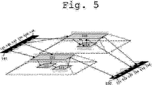
図5は、たとえば試作用ハードウェアのためのプラットフォーム・ソフトウェアプログラムが組み込まれた後における、図4と等価な機能100の図面を示している。組み込みによって局所性原則への違反が生じており、センサコンポーネントおよびアクチュエータコンポーネントの機能的なカプセル化が失われている。 FIG. 5 shows a diagram of a function 100 equivalent to FIG. 4, for example, after a platform software program for prototyping hardware has been incorporated. Incorporation has violated locality principles and has lost the functional encapsulation of sensor and actuator components.
機能100は、それぞれリーフコンポーネント122,123および114を備える、サブ機能110および120を同じく有している。これに加えて、入力プラットフォーム・ソフトウェアコンポーネント140と出力プラットフォーム・ソフトウェアコンポーネント150が図示されている。入力プラットフォーム・ソフトウェアコンポーネント140は、付属の試作用ハードウェアの物理的な条件に呼応する複数のチャネルコンポーネント141から146を有している。同様に、出力プラットフォーム・ソフトウェアコンポーネント150も、付属の試作用ハードウェアの物理的な条件に呼応する複数のチャネルコンポーネント151から156を有している。チャネルコンポーネントまたはチャネル142,143,145,152,153,154は、占有または接続されていない。
Function 100 also has sub-functions 110 and 120 with leaf components 122, 123 and 114, respectively. In addition, an input platform software component 140 and an output
このプラットフォーム指向の図面では、チャネルコンポーネントおよびリーフコンポーネントのすべての接続が、グローバルに可視的になっている。図1から図4に示す以前の図面に存在しているセンサコンポーネント130,111および121は、入力プラットフォーム・ソフトウェアコンポーネント140のチャネル144,146および141で置き換えられており、すなわち、130は144で、111は146で、そして121は141でそれぞれ置き換えられている。 In this platform-oriented drawing, all connections of channel components and leaf components are globally visible. The sensor components 130, 111 and 121 present in the previous drawings shown in FIGS. 1 to 4 have been replaced by the channels 144, 146 and 141 of the input platform software component 140, i.e. 130 is 144, 111 is replaced with 146, and 121 is replaced with 141.
同様に、アクチュエータコンポーネント124,113および112は、出力プラットフォーム・ソフトウェアコンポーネント150のチャネル151,155および156で置き換えられており、すなわち、124は151で、113は155で、そして112は156で置き換えられている。
Similarly, actuator components 124, 113 and 112 have been replaced with channels 151, 155 and 156 of output
この図面では、チャネル144からリーフコンポーネント110および130への接続を例にとって図示されているチャネルからリーフコンポーネントへの接続は、別々に(アンバンドリングして)通じている。そのほか、接続を共同で(バンドリングして)通すことも同じく可能である。これは、接続されるリーフコンポーネントが1つの階層レベルに位置している場合に適している。そのような場合(図示せず)、ケーブルから階層レベルまでは接続が共同で延びて、そこで初めて分割される(アンバンドリングされる)。当然ながら、リーフコンポーネントを接続するときのこのようなケーブルのバンドリングとアンバンドリングは、入力プラットフォーム・ソフトウェアコンポーネントだけでなく、出力プラットフォーム・ソフトウェアコンポーネントでも利用することができる。 In this figure, the channel to leaf component connections illustrated by way of example from the channel 144 to the leaf components 110 and 130 are separate (unbundled). In addition, it is also possible to pass the connections together (bundling). This is suitable when the leaf components to be connected are located at one hierarchical level. In such a case (not shown), the connection extends jointly from the cable to the hierarchical level, where it is first split (unbundled). Of course, such bundling and unbundling of cables when connecting leaf components can be utilized not only for input platform software components but also for output platform software components.
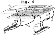
図6は、本発明の方法の有利な実施形態に基づく、たとえば試作用ハードウェアのためのプラットフォーム・ソフトウェアプログラムが組み込まれた後における図4と等価な機能100の図面を示している。 FIG. 6 shows a diagram of a function 100 equivalent to FIG. 4 after a platform software program, for example for prototyping hardware, has been incorporated, according to an advantageous embodiment of the method of the invention.
機能100は、両方のサブ機能110および120と、センサ信号を両方のサブ機能110および120に提供するセンサコンポーネント130とを有している。 The function 100 includes both sub-functions 110 and 120 and a sensor component 130 that provides sensor signals to both sub-functions 110 and 120.
サブ機能110は、局所的なセンサコンポーネント111と、両方の局所的なアクチュエータコンポーネント112,113と、リーフコンポーネント114とを有している。センサコンポーネント111とアクチュエータコンポーネント112,113は、サブ機能110の内部で機能的にカプセル化されている。 The sub-function 110 has a local sensor component 111, both local actuator components 112, 113, and a leaf component 114. The sensor component 111 and the actuator components 112 and 113 are functionally encapsulated inside the sub-function 110.
サブ機能120は、局所的なセンサコンポーネント121と、両方の局所的なリーフコンポーネント122,123と、局所的なアクチュエータコンポーネント124とを有している。センサコンポーネント121とアクチュエータコンポーネント124は、サブ機能120の内部で機能的にカプセル化されている。 The sub-function 120 has a local sensor component 121, both local leaf components 122, 123 and a local actuator component 124. Sensor component 121 and actuator component 124 are functionally encapsulated within sub-function 120.
さらに、チャネル141から146を備える入力プラットフォーム・ソフトウェアプログラム140と、チャネル151から156を備える出力プラットフォーム・ソフトウェアプログラム150とが図示されている。チャネルの数は、付属の試作用ハードウェアの物理的な条件に呼応している。チャネル142,143,145,152,153,154は、占有または接続されていない。
In addition, an input platform software program 140 comprising channels 141 to 146 and an output
本発明による方法の有利な実施形態のマッピング規則は、黒の矢印160から165でグラフィック表示されている。プラットフォーム・ソフトウェアコンポーネント140および150を含めたマッピング矢印160から165は、モデリング段階では可視的ではない。
The mapping rules of an advantageous embodiment of the method according to the invention are graphically represented by black arrows 160 to 165. Mapping arrows 160-165, including
従来の方法では、たとえば試作用ハードウェアのモデリング段階のときに、図5に示すようなモデルが生成される。本発明による方法の有利な実施形態では、これに代えて図4〜図6に示すようなモデルが生成され、このモデルでは、局所的なセンサコンポーネントとアクチュエータコンポーネント130,121,124,111,112,113が、プラットフォーム・ソフトウェアコンポーネント140および150のチャネルコンポーネント141から146および151から156のためのワイルドカードとしての役目をする。
In the conventional method, for example, a model as shown in FIG. 5 is generated at the time of modeling the prototype hardware. In an advantageous embodiment of the method according to the invention, a model as shown in FIGS. 4 to 6 is generated instead, in which the local sensor and actuator components 130, 121, 124, 111, 112 are generated. , 113 serves as a wildcard for the channel components 141-146 and 151-156 of the
マッピング規則は、図6に示す本発明の方法の有利な実施形態では、グラフィック表示160から165として存在している。 The mapping rules are present as graphical representations 160-165 in the preferred embodiment of the method of the invention shown in FIG.
既にプラットフォームの視界内に存在している図5の階層モデルから、図4〜図6に示すワイルドカードを含むモデルを生成するのも同様に好ましい。 It is also preferable to generate a model including wildcards shown in FIGS. 4 to 6 from the hierarchical model of FIG. 5 that already exists in the field of view of the platform.
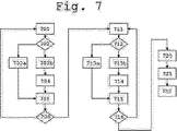
本発明による方法の有利な実施形態が、図7に示されている。プラットフォームの視界内にあるモデルを出発点として、次のような方法ステップが実施される。 An advantageous embodiment of the method according to the invention is shown in FIG. The following method steps are performed starting from a model that is in the field of view of the platform.
ステップ701では、入力ソフトウェアコンポーネントのチャネルコンポーネントを起点として、リーフコンポーネントまたはチャネルアンバンドリングに達するまで、接続された各々の階層コンポーネントを介しての接続が引き伸ばされる。 In step 701, starting from the channel component of the input software component, the connection through each connected hierarchical component is extended until a leaf component or channel unbundling is reached.
ステップ702では、チャネルが、どれだけの数のコンポーネントおよびチャネルアンバンドリングと接続されているかが判定される。チャネルがちょうど1つのコンポーネントまたはチャネルアンバンドリングと接続されているときは、ステップ703aへ進む。チャネルが1つを超えるコンポーネント及び/又はチャネルアンバンドリングと接続されているときは、ステップ703bへ進む。
In
ステップ703aでは、コンポーネントまたはチャネルアンバンドリングへのチャネルの接続が解消され、コンポーネントまたはチャネルアンバンドリングを含んでいるリーフ機能の階層レベルで局所的なセンサコンポーネントがワイルドカードとして生成され、当初はチャネルまたはチャネルアンバンドリングと直接接続されていたリーフコンポーネントと接続される。チャネルアンバンドリングが除去される。 In step 703a, the connection of the channel to the component or channel unbundling is broken, and a local sensor component is generated as a wildcard at the hierarchical level of the leaf function that includes the component or channel unbundling, initially the channel Or it is connected with the leaf component which was directly connected with the channel unbundling. Channel unbundling is removed.
ステップ703bでは、チャネルが接続されている他の各々のコンポーネントまたはチャネルアンバンドリングが探索され、その階層レベルが判定される。ステップ704では、局所的なセンサコンポーネントがワイルドカードとして共通の最上位の階層レベルに設置され、リーフコンポーネント及び/又は階層的に下位に位置するチャネルアンバンドリングと接続される。最上位の階層レベルにあるチャネルアンバンドリングは除去される。リーフコンポーネント及び/又はチャネルアンバンドリングへのチャネルの接続が分断される。 In step 703b, each other component or channel unbundling to which the channel is connected is searched and its hierarchical level is determined. In step 704, local sensor components are installed as wildcards at a common top hierarchical level and connected to leaf components and / or channel unbundling located hierarchically below. Channel unbundling at the highest hierarchical level is removed. The connection of the channel to the leaf component and / or channel unbundling is broken.
ステップ705では、それぞれ703aまたは704で作成されたセンサコンポーネントについて、追加されるべき局所的なセンサコンポーネント(=ワイルドカード)の名称または識別子を入力プラットフォームソフトウェアコンポーネントの相応のチャネルコンポーネントに割り当てる登録が、たとえばリスト形式の構造で生成される。 In step 705, for the sensor component created at 703a or 704, respectively, registration to assign the name or identifier of the local sensor component (= wildcard) to be added to the corresponding channel component of the input platform software component is Generated in list format structure.
ステップ706では、リーフコンポーネントと接続されている、入力プラットフォームソフトウェアコンポーネントの次のチャネルが判定され、ステップ701で手順が続行される。ほかに接続されているチャネルがないときは、ステップ711へ進む。 In step 706, the next channel of the input platform software component that is connected to the leaf component is determined, and in step 701 the procedure continues. If there is no other connected channel, the process proceeds to step 711.
ステップ711では、出力ソフトウェアコンポーネントのチャネルコンポーネントを起点として、リーフコンポーネントまたはチャネルアンバンドリングに達するまで、接続された各々の階層コンポーネントを介しての接続が引き伸ばされる。 In step 711, starting from the channel component of the output software component, the connection through each connected hierarchical component is extended until a leaf component or channel unbundling is reached.
ステップ712では、チャネルが、どれだけの数のコンポーネントおよびチャネルアンバンドリングと接続されているかが判定される。チャネルがちょうど1つのコンポーネントまたはチャネルアンバンドリングと接続されているときは、ステップ713aへ進む。チャネルが1つを超えるコンポーネント及び/又はチャネルアンバンドリングと接続されているときは、ステップ713bへ進む。 In step 712, it is determined how many components and channel unbundling the channel is connected to. If the channel is connected with exactly one component or channel unbundling, go to step 713a. If the channel is connected to more than one component and / or channel unbundling, go to step 713b.
ステップ713aでは、コンポーネントまたはチャネルアンバンドリングへのチャネルの接続が解消され、コンポーネントまたはチャネルアンバンドリングを含んでいるリーフ機能の階層レベルで局所的なアクチュエータコンポーネントがワイルドカードとして生成され、当初はチャネルまたはチャネルアンバンドリングと直接接続されていたリーフコンポーネントと接続される。チャネルアンバンドリングが除去される。 In step 713a, the connection of the channel to the component or channel unbundling is broken, and a local actuator component is generated as a wildcard at the hierarchical level of the leaf function that includes the component or channel unbundling, initially channel Or it is connected with the leaf component which was directly connected with the channel unbundling. Channel unbundling is removed.
ステップ713bでは、チャネルが接続されている他の各々のコンポーネントまたはチャネルアンバンドリングが探索され、その階層レベルが判定される。ステップ714では、局所的なアクチュエータコンポーネントがワイルドカードとして共通の最上位の階層レベルに設置され、リーフコンポーネント及び/又は階層的に下位に位置するチャネルアンバンドリングと接続される。最上位の階層レベルにあるチャネルアンバンドリングは除去される。リーフコンポーネント及び/又はチャネルアンバンドリングへのチャネルの接続が分断される。 In step 713b, each other component or channel unbundling to which the channel is connected is searched and its hierarchical level is determined. In step 714, local actuator components are installed as wildcards at a common top hierarchical level and connected to leaf components and / or channel unbundling located hierarchically below. Channel unbundling at the highest hierarchical level is removed. The connection of the channel to the leaf component and / or channel unbundling is broken.
ステップ715では、それぞれ713aまたは714で作成されたアクチュエータコンポーネントについて、追加されるべき局所的なアクチュエータコンポーネント(=ワイルドカード)の名称または識別子を出力プラットフォームソフトウェアコンポーネントの相応のチャネルに割り当てる登録が、リスト形式の構造で生成される。 In step 715, for the actuator component created at 713a or 714, respectively, registration to assign the name or identifier of the local actuator component (= wildcard) to be added to the corresponding channel of the output platform software component is in list form It is generated with the structure.
ステップ716では、リーフコンポーネントと接続されている、入力プラットフォームソフトウェアコンポーネントの次のチャネルが判定され、ステップ711で手順が続行される。ほかに接続されているチャネルがないときは、ステップ720で方法を続行する。 In step 716, the next channel of the input platform software component connected to the leaf component is determined, and the procedure continues in step 711. If there are no other connected channels, the method continues at step 720.
ステップ720では、リスト形式の構造に基づく生成されたマッピング規則を用いて、ワイルドカードがプラットフォーム・ソフトウェアコンポーネントまたはそのチャネルで置き換えられ、実行可能なプログラムコードが生成される。 In step 720, using the generated mapping rules based on the structure of the list format, the wildcard is replaced with the platform software component or its channel to generate executable program code.
ステップ721では、本発明による方法の有利な実施形態に基づく実行可能なプログラムコードが、有利には試作用ハードウェアであるコンピュータ装置に伝送される。 In step 721, executable program code according to an advantageous embodiment of the method according to the invention is transmitted to a computer device, which is advantageously prototyping hardware.
ステップ722では、伝送された実行可能なプログラムコードを用いてコンピュータ装置が作動する。 In step 722, the computer device operates using the transmitted executable program code.
Claims (9)
前記コンポーネントは、前記ワイルドカードとして利用される局所的なセンサコンポーネント及び局所的なアクチュエータコンポーネントを含み、
前記ワイルドカードとして利用される局所的なセンサコンポーネント及び局所的なアクチュエータコンポーネントは、前記第1のコンピュータ装置の物理的な条件に対応するチャネルコンポーネントと接続され、
前記ワイルドカードは、相応に作成されたマッピング規則により、前記実行可能なプログラムコードの作成前に前記チャネルコンポーネントで置き換えられることを特徴とする、方法。A method of operating a first computer system, a source program code created containing functional model, the functional model, features that component is being hierarchically combined is configured by hierarchically combined and visibility of the components inside the functional model is defined by the hierarchy, wildcard is utilized within the hierarchy with the particular component, executable program code is generated, in the method,
The components include a local sensor component and a local actuator component utilized as the wildcard,
A local sensor component and a local actuator component utilized as the wildcard are connected to a channel component corresponding to a physical condition of the first computing device;
The wildcard is more mapping rules created correspondingly, characterized in that it is replaced with the channel components before creating the executable program code, the method.
Applications Claiming Priority (3)
| Application Number | Priority Date | Filing Date | Title |
|---|---|---|---|
| DE102004057263A DE102004057263A1 (en) | 2004-11-26 | 2004-11-26 | Method for operating a computer device |
| DE102004057263.1 | 2004-11-26 | ||
| PCT/EP2005/056230 WO2006056601A1 (en) | 2004-11-26 | 2005-11-25 | Method for operating a computer device |
Publications (2)
| Publication Number | Publication Date |
|---|---|
| JP2008522266A JP2008522266A (en) | 2008-06-26 |
| JP4917543B2 true JP4917543B2 (en) | 2012-04-18 |
Family
ID=35645693
Family Applications (1)
| Application Number | Title | Priority Date | Filing Date |
|---|---|---|---|
| JP2007541990A Expired - Fee Related JP4917543B2 (en) | 2004-11-26 | 2005-11-25 | Method for operating a computer device |
Country Status (5)
| Country | Link |
|---|---|
| US (1) | US8769489B2 (en) |
| EP (1) | EP1820095A1 (en) |
| JP (1) | JP4917543B2 (en) |
| DE (1) | DE102004057263A1 (en) |
| WO (1) | WO2006056601A1 (en) |
Family Cites Families (3)
| Publication number | Priority date | Publication date | Assignee | Title |
|---|---|---|---|---|
| JP4743944B2 (en) * | 2000-08-25 | 2011-08-10 | 鎮男 角田 | Simulation model creation method and system and storage medium |
| US6701501B2 (en) | 2000-10-16 | 2004-03-02 | Simon Joshua Waters | Structured algorithmic programming language approach to system design |
| JP4727896B2 (en) | 2001-06-27 | 2011-07-20 | ローベルト ボッシュ ゲゼルシャフト ミット ベシュレンクテル ハフツング | System functionality monitoring method, monitoring device thereof, memory device, computer program |
-
2004
- 2004-11-26 DE DE102004057263A patent/DE102004057263A1/en not_active Ceased
-
2005
- 2005-11-25 WO PCT/EP2005/056230 patent/WO2006056601A1/en not_active Ceased
- 2005-11-25 JP JP2007541990A patent/JP4917543B2/en not_active Expired - Fee Related
- 2005-11-25 EP EP05817437A patent/EP1820095A1/en not_active Ceased
- 2005-11-25 US US11/666,834 patent/US8769489B2/en not_active Expired - Fee Related
Also Published As
| Publication number | Publication date |
|---|---|
| WO2006056601A1 (en) | 2006-06-01 |
| US8769489B2 (en) | 2014-07-01 |
| JP2008522266A (en) | 2008-06-26 |
| US20110119650A1 (en) | 2011-05-19 |
| DE102004057263A1 (en) | 2006-06-01 |
| EP1820095A1 (en) | 2007-08-22 |
Similar Documents
| Publication | Publication Date | Title |
|---|---|---|
| EP4002189A1 (en) | Industrial network communication emulation | |
| Reinhardt et al. | Domain controlled architecture | |
| US8577654B2 (en) | Bi-directional projection | |
| CN111954871A (en) | Method for providing application data of applications that can be implemented in a control device of a vehicle, a control device and a method for calibrating the same, and an analysis and processing device | |
| EP3872635A1 (en) | In-vehicle equipment controller and vehicle control system | |
| JP2012208843A (en) | Development support device | |
| Temperekidis et al. | Towards a digital twin architecture with formal analysis capabilities for learning-enabled autonomous systems | |
| CN105190625B (en) | Method for manufacturing complex product, especially automobile | |
| JP4917543B2 (en) | Method for operating a computer device | |
| US20070271551A1 (en) | Electronic Control Unit and Method for Specifying a Software Architecture for an Electronic Control Unit | |
| US20100161678A1 (en) | Method and apparatus for utilizing matlab functionality in java-enabled environment | |
| CN108376288B (en) | Electric vehicle maintenance method and equipment based on big data technology | |
| Axelsson | Holistic object-oriented modelling of distributed automotive real-time control applications | |
| Căpriţă et al. | Safety automotive sensors and actuators with end-to-end protection (E2E) in the context of AUTOSAR embedded applications | |
| US10386806B2 (en) | Method for connecting models of technical systems in a testing device equipped for control unit development | |
| KR20200082314A (en) | Method and apparatus for designing VFB of AUTOSAR using a FBF (Function Block Feature) | |
| CN111177877A (en) | Local simulation method, device and storage medium based on application container engine | |
| US12367172B2 (en) | System-on-chip, data processing system having the same, and operating method thereof preliminary | |
| Wagner et al. | Virtualization for Verifying Functional Safety of Highly Automated Driving Using the Example of a Real ECU Project | |
| WO2005124571A1 (en) | Mutual access method of data and mutual access system of data | |
| Stroop et al. | Prototyping of automotive control systems in a time-triggered environment using flexray | |
| Feilhauer et al. | A multi-domain simulation approach to validate Advanced Driver Assistance Systems | |
| Nazareth et al. | Development of an AUTOSAR software component based on the V-model | |
| Căpriță et al. | Integrating AUTOSAR end-to-end communication protection library inside automotive actuators | |
| Kulaczewski et al. | How Processors Adapt to Changing Vehicle Architectures |
Legal Events
| Date | Code | Title | Description |
|---|---|---|---|
| A621 | Written request for application examination |
Free format text: JAPANESE INTERMEDIATE CODE: A621 Effective date: 20070525 |
|
| A131 | Notification of reasons for refusal |
Free format text: JAPANESE INTERMEDIATE CODE: A131 Effective date: 20101102 |
|
| A601 | Written request for extension of time |
Free format text: JAPANESE INTERMEDIATE CODE: A601 Effective date: 20110202 |
|
| A602 | Written permission of extension of time |
Free format text: JAPANESE INTERMEDIATE CODE: A602 Effective date: 20110210 |
|
| A521 | Request for written amendment filed |
Free format text: JAPANESE INTERMEDIATE CODE: A523 Effective date: 20110228 |
|
| TRDD | Decision of grant or rejection written | ||
| A01 | Written decision to grant a patent or to grant a registration (utility model) |
Free format text: JAPANESE INTERMEDIATE CODE: A01 Effective date: 20111227 |
|
| A01 | Written decision to grant a patent or to grant a registration (utility model) |
Free format text: JAPANESE INTERMEDIATE CODE: A01 |
|
| A61 | First payment of annual fees (during grant procedure) |
Free format text: JAPANESE INTERMEDIATE CODE: A61 Effective date: 20120126 |
|
| FPAY | Renewal fee payment (event date is renewal date of database) |
Free format text: PAYMENT UNTIL: 20150203 Year of fee payment: 3 |
|
| R150 | Certificate of patent or registration of utility model |
Ref document number: 4917543 Country of ref document: JP Free format text: JAPANESE INTERMEDIATE CODE: R150 Free format text: JAPANESE INTERMEDIATE CODE: R150 |
|
| R250 | Receipt of annual fees |
Free format text: JAPANESE INTERMEDIATE CODE: R250 |
|
| R250 | Receipt of annual fees |
Free format text: JAPANESE INTERMEDIATE CODE: R250 |
|
| R250 | Receipt of annual fees |
Free format text: JAPANESE INTERMEDIATE CODE: R250 |
|
| R250 | Receipt of annual fees |
Free format text: JAPANESE INTERMEDIATE CODE: R250 |
|
| R250 | Receipt of annual fees |
Free format text: JAPANESE INTERMEDIATE CODE: R250 |
|
| R250 | Receipt of annual fees |
Free format text: JAPANESE INTERMEDIATE CODE: R250 |
|
| LAPS | Cancellation because of no payment of annual fees |