JP4915224B2 - Information processing method, information processing apparatus, recording medium, program, and control apparatus - Google Patents
Information processing method, information processing apparatus, recording medium, program, and control apparatus Download PDFInfo
- Publication number
- JP4915224B2 JP4915224B2 JP2006324483A JP2006324483A JP4915224B2 JP 4915224 B2 JP4915224 B2 JP 4915224B2 JP 2006324483 A JP2006324483 A JP 2006324483A JP 2006324483 A JP2006324483 A JP 2006324483A JP 4915224 B2 JP4915224 B2 JP 4915224B2
- Authority
- JP
- Japan
- Prior art keywords
- power supply
- uninterruptible power
- information processing
- state
- processing apparatus
- Prior art date
- Legal status (The legal status is an assumption and is not a legal conclusion. Google has not performed a legal analysis and makes no representation as to the accuracy of the status listed.)
- Active
Links
Images


Description
本発明は、情報処理方法、情報処理装置、記録媒体、およびプログラム、並びに制御装置に関し、特に、複数の無停電電源装置を介して供給された電力を電源として動作する場合に用いて好適な情報処理方法、情報処理装置、記録媒体、およびプログラム、並びに制御装置に関する。 The present invention relates to an information processing method, an information processing device, a recording medium, a program, and a control device, and in particular, information suitable for use when operating with power supplied through a plurality of uninterruptible power supply devices. The present invention relates to a processing method, an information processing device, a recording medium, a program, and a control device.
近年、パーソナルコンピュータに代表される情報処理装置の普及が進んでおり、その重要性は年々増している。 In recent years, information processing apparatuses represented by personal computers have been widely used, and their importance has been increasing year by year.
情報処理装置の駆動に使用される電力は、商用交流電源から直接供給されることが多いので、例えば、商用交流電源の瞬間的な電圧の低下(瞬断)や突然の停電等の異常が発生すると、その時点で情報処理装置によって処理されていた情報が破損したり、損失してしまったりする他、内蔵するハードディスク等が故障してしまう等の情報処理装置に不具合が発生することも起こり得る。 Since power used to drive information processing devices is often supplied directly from commercial AC power, abnormalities such as momentary voltage drop (instant interruption) or sudden power outages of commercial AC power occur. Then, the information processed by the information processing device at that time may be damaged or lost, and a failure may occur in the information processing device such as a failure of the built-in hard disk or the like. .
そこで、このような不具合の発生を回避するため、商用交流電源と情報処理装置との間に無停電電源装置(以下、UPS(Uninterruptible Power Supply)とも称する)を設ける方法がある(例えば、特許文献1参照)。 In order to avoid the occurrence of such problems, there is a method of providing an uninterruptible power supply (hereinafter also referred to as UPS (Uninterruptible Power Supply)) between the commercial AC power supply and the information processing apparatus (for example, Patent Document 1).
このUPSは、商用交流電源が正常である場合、商用交流電源からの電力を情報処理装置に供給し、商用交流電源に異常が発生した場合、商用交流電源からの電力に代えて、内蔵するバッテリからの電力を情報処理装置に供給するようになされている。 This UPS supplies power from the commercial AC power source to the information processing device when the commercial AC power source is normal, and replaces the power from the commercial AC power source when an abnormality occurs in the commercial AC power source. Is supplied to the information processing apparatus.
したがって、このようなUPSの動作により、UPSを介して電力が供給される情報処理装置は、商用交流電源に異常が発生したとしても、UPS内のバッテリから供給される電力を電源として実行中の処理をそのまま続行することが可能となる。 Therefore, an information processing apparatus to which power is supplied via the UPS by such an operation of the UPS is being executed using the power supplied from the battery in the UPS as the power supply even if an abnormality occurs in the commercial AC power supply. It becomes possible to continue the processing as it is.
しかしながら、UPSに内蔵されているバッテリは、あくまでも予備電源であって、その電力供給能力に限りがある。即ち、バッテリが所定のレベル以上の電圧を出力可能な時間(以下、給電可能時間と称する)には限りがあり、UPSのバッテリに給電可能時間の限りがあるが故、情報処理装置とUPSのそれぞれは動作を制限する必要が生ずる。 However, the battery built in the UPS is a standby power source, and its power supply capability is limited. In other words, there is a limit to the time during which the battery can output a voltage of a predetermined level or higher (hereinafter referred to as “power supply time”), and the power supply time to the UPS battery is limited. Each needs to be restricted in operation.
一方の情報処理装置は、商用交流電源の異常発生に対応してUPSに内蔵されたバッテリから電力供給を受けた場合、UPSの給電可能時間以内に、これまで実行していた処理を停止させ、予め定められた手順に従って、自分自身の状態を稼動状態から電力供給が遮断されても不都合の生じない休止状態に遷移させる処理(以下、このような一連の処理を、シャットダウン処理と称する)を実行する必要がある。 When one information processing device receives power supply from the battery built into the UPS in response to the occurrence of an abnormality in the commercial AC power supply, it stops the processing that has been executed so far within the UPS power supply time, In accordance with a predetermined procedure, a process of transitioning from the operating state to the hibernate state in which no inconvenience occurs even if the power supply is cut off from the operating state (hereinafter, such a series of processes is referred to as a shutdown process) is executed. There is a need to.
具体的には、例えば、情報処理装置がパーソナルコンピュータ等である場合、情報処理装置では所定のOS(Operating System)が起動され、当該OS上で動作するアプリケーションプログラムが実行されていることが多いので、この場合、シャットダウン処理として、各アプリケーションプログラムにて処理中のデータを適宜保存した後、実行中のアプリケーションプログラムを終了し、OSを休止する処理を実行することになる。 Specifically, for example, when the information processing apparatus is a personal computer or the like, a predetermined OS (Operating System) is started in the information processing apparatus, and application programs that run on the OS are often executed. In this case, as the shutdown process, after the data being processed by each application program is appropriately saved, the application program being executed is terminated and the OS is suspended.
他方のUPSは、内蔵するバッテリの放電(情報処理装置に対する給電)が過度に行われると、バッテリの寿命が短縮されたり、再充電しても使用不可能(仕様を満たすレベルの電圧で再放電することが不可能)となってしまったりするなどの不具合が発生してしまう。そこで、このような不具合の発生を抑止するため、UPSは、情報処理装置がシャットダウン処理を完了した後、できるだけ速やかにバッテリの放電を停止させる処理、即ち、そのUPSの状態を、電力を供給している稼動状態から、その供給を止める停止状態に遷移させる処理(以下、このような処理を、UPS停止処理と称する)を実行する必要がある。 The other UPS, if the built-in battery is discharged excessively (powering the information processing device), the battery life is shortened or it cannot be used even if it is recharged (redischarged at a voltage level that meets the specifications). It is impossible to do this). Therefore, in order to suppress the occurrence of such a malfunction, the UPS supplies power to the process of stopping the battery discharge as soon as possible after the information processing apparatus completes the shutdown process, that is, the state of the UPS. It is necessary to execute a process of transitioning from a running state to a stopped state in which the supply is stopped (hereinafter, such a process is referred to as a UPS stop process).
そこで、UPSにUPS停止処理を実行させる方法として、本出願人は、情報処理装置からUPSによるUPS停止処理を制御するためのプログラム(以下、UPS制御プログラムと称する)を開発し、既に販売を行っている。 Therefore, as a method for causing UPS to execute UPS stop processing, the present applicant has developed a program for controlling UPS stop processing by UPS from an information processing device (hereinafter referred to as UPS control program) and has already sold it. ing.
このUPS制御プログラムがインストールされた情報処理装置は、当該情報処理装置に接続されている1台のUPSの状態を監視し、UPSに入力される商用交流電源に異常が発生した場合、自身のシャットダウン処理を実行するとともに、その1台のUPSに対して、UPS停止処理を実行させることができる。 The information processing device installed with this UPS control program monitors the status of one UPS connected to the information processing device, and shuts down when an abnormality occurs in the commercial AC power input to the UPS. While executing the process, the UPS stop process can be executed for the one UPS.
ところで、近年、電源異常に対処する他の対策(即ち、情報処置装置と商用交流電源との間にUPSを接続するという対策とは異なる対策)として、情報処置装置自身の給電部位に冗長性を持たせる機能(以下、冗長電源機能と称する)を設けることも行われつつある。 By the way, in recent years, as another measure for dealing with a power supply abnormality (that is, a measure different from the measure of connecting a UPS between the information processing apparatus and the commercial AC power supply), redundancy has been added to the power supply portion of the information processing apparatus itself. A function to be provided (hereinafter referred to as a redundant power supply function) is also being provided.
即ち、冗長電源機能を有する情報処理装置の給電部位には、複数の電源ユニットが設けられており、例えば、これら複数の電源ユニットのいずれかに異常が発生した場合、残りの電源ユニットで、その情報処理装置に必要な電力を供給することができる。 That is, a plurality of power supply units are provided in the power supply part of the information processing apparatus having a redundant power supply function. For example, when an abnormality occurs in any of the plurality of power supply units, the remaining power supply units Necessary power can be supplied to the information processing apparatus.
さらに、このような冗長電源機能を有する情報処理装置の各電源ユニットに対して、それぞれ異なるUPSを介して商用交流電源を供給するようにすれば、電源異常に対する情報処理装置の信頼性をさらに高めることができる。 Furthermore, if the commercial AC power supply is supplied to each power supply unit of the information processing apparatus having such a redundant power supply function via a different UPS, the reliability of the information processing apparatus against power supply abnormality is further improved. be able to.
このように、冗長電源機能を有する情報処理装置の各電源ユニットに対して、それぞれ異なるUPSを介して商用交流電源を供給する場合、複数の各UPSが上述したUPS停止処理を実行できるように、上述したUPS制御プログラムを発展させ、複数のUPSを制御できるようにする方法(特許文献2参照)や、各UPSに対してUPS停止処理を実行させるための制御装置を設ける方法などがある。 In this way, when supplying commercial AC power to each power supply unit of the information processing apparatus having a redundant power supply function via a different UPS, so that a plurality of UPSs can execute the UPS stop process described above, There are a method of developing the above-described UPS control program so that a plurality of UPSs can be controlled (see Patent Document 2), a method of providing a control device for causing each UPS to execute a UPS stop process, and the like.
しかしながら、特許文献2に記載の方法においては、情報処理装置と各UPSとを制御用の専用回線で接続する必要がある。各UPSに対して制御装置を設ける方法においては、情報処理装置と各制御装置とを制御用の専用回線で接続する必要がある。したがって、冗長電源機能を有する情報処理装置の各電源ユニットに対して、それぞれ異なるUPSを介して商用交流電源を供給する場合において、複数の各UPSが上述したUPS停止処理を実行できるようにするには、既存の方法では、システムとしての設置に制約が生じてしまう。
However, in the method described in
システムとしての設置に制約を生じさせない方法としては、情報処理装置と各UPSあるいは各制御装置とを汎用性の高いLAN(Local Area Network)などのネットワークを介して接続できるようにする、換言すれば、情報処理装置から汎用性の高いネットワークを介して各UPSを制御する制御装置を制御できるようにすることが望ましい。 As a method that does not limit the installation as a system, the information processing device and each UPS or each control device can be connected via a network such as a highly versatile LAN (Local Area Network). It is desirable that the control device that controls each UPS can be controlled from the information processing device via a highly versatile network.
本発明は、このような状況に鑑みてなされたものであり、冗長電源機能を有する情報処理装置の各電源ユニットに対して、それぞれ異なるUPSを介して商用交流電源を供給する場合、情報処理装置から汎用性の高いネットワークを介して各UPSを制御する制御装置を制御できるようにするものである。 The present invention has been made in view of such a situation, and in the case of supplying commercial AC power to each power supply unit of an information processing apparatus having a redundant power supply function via a different UPS, the information processing apparatus Therefore, it is possible to control a control device that controls each UPS via a highly versatile network.
本発明の第1の側面である情報処理方法は、無停電電源装置を制御する制御装置とネットワークを介して通信する通信手段を備え、複数の前記無停電電源装置から供給される電力を電源として動作する情報処理装置の情報処理方法において、前記無停電電源装置の状態をユーザに提示するための、前記制御装置から前記ネットワークを介して通知された前記無停電電源装置の状態を示す状態情報を取得する第1の取得ステップと、複数の前記制御装置から前記ネットワークを介して通知され得るシャットダウン処理命令を取得する第2の取得ステップと、取得された前記シャットダウン処理命令の数に基づいて、前記情報処理装置を稼動状態から休止状態に遷移させる状態遷移ステップとを含み、前記制御装置においては、前記無停電電源装置の状態を監視し、前記無停電電源装置の監視結果、予め設定されているタイミング、またはユーザからの所定の操作に対応し、前記無停電電源装置の停止処理を制御するとともに、前記情報処理装置に対して稼動状態から休止状態に遷移するように指示するシャットダウン処理命令を生成し、前記無停電電源装置の監視結果に基づく前記無停電電源装置の状態情報を前記ネットワークを介して前記情報処理装置に通知するとともに、生成された前記シャットダウン処理命令を前記ネットワークを介して前記情報処理装置に通知することを特徴とする。 An information processing method according to a first aspect of the present invention includes a communication unit that communicates with a control device that controls an uninterruptible power supply device via a network, and uses power supplied from the plurality of uninterruptible power supply devices as a power source. In the information processing method of the information processing apparatus that operates, the state information indicating the state of the uninterruptible power supply notified from the control device via the network for presenting the state of the uninterruptible power supply to the user Based on a first acquisition step to acquire, a second acquisition step to acquire a shutdown processing instruction that can be notified from the plurality of control devices via the network, and the number of acquired shutdown processing instructions, and a state transition step of transitioning the information processing apparatus from the operating state to the resting state seen including, in the control device, the uninterruptible power supply In response to a monitoring result of the uninterruptible power supply, a preset timing, or a predetermined operation from the user, and controlling the stop processing of the uninterruptible power supply, and the information processing apparatus Generates a shutdown processing instruction for instructing the transition from the operating state to the hibernation state, and transmits the state information of the uninterruptible power supply based on the monitoring result of the uninterruptible power supply to the information processing apparatus via the network And the generated shutdown processing instruction is notified to the information processing apparatus via the network .
本発明の第1の側面である情報処理方法においては、無停電電源装置の状態をユーザに提示するための、制御装置から前記ネットワークを介して通知された無停電電源装置の状態を示す状態情報が取得される。また、複数の制御装置から通知され得るシャットダウン処理命令が取得され、取得されたシャットダウン処理命令の数に基づいて、情報処理装置が稼動状態から休止状態に遷移される。 In the information processing method according to the first aspect of the present invention, state information indicating the state of the uninterruptible power supply notified from the control device via the network for presenting the state of the uninterruptible power supply to the user Is acquired. Further, the shutdown processing instructions may be notified from a plurality of control devices is obtained, based on the number of shutdown processing instruction acquired, the information processing apparatus is shifted from the operating state to the resting state.
したがって、情報処理装置の稼動状態を可能な限り維持しつつ、情報処理装置にシャットダウン処理を行うことができる。 Therefore, it is possible to perform a shutdown process on the information processing apparatus while maintaining the operating state of the information processing apparatus as much as possible.
この情報処理装置は、CPU(Central Processing Unit)を備えるコンピュータに適用することができる。ネットワークには、例えば汎用性の高いTCP/IP(Transmission Control Protocol/Internet Protocol)を用いるLANを適用することができる。 This information processing apparatus can be applied to a computer having a CPU (Central Processing Unit). For example, a highly versatile LAN using TCP / IP (Transmission Control Protocol / Internet Protocol) can be applied to the network.
前記状態情報は、前記無停電電源装置が稼働中であるか否かを示す第1の項目、異常が発生しているか否かを示す第2の項目、および、発生している異常は前記無停電電源装置自体の異常であるのかまたは前記無停電電源装置の入力電源である商用交流電源の異常であるのかを示す第3の項目を含むことができる。
本発明の第1の側面である情報処理方法は、取得された前記状態情報に基づいて前記無停電電源装置の状態をユーザに提示する提示ステップをさらに含むことができる。
これによりユーザは、前記無停電電源装置の状態を把握することができる。
The status information includes a first item indicating whether or not the uninterruptible power supply is in operation, a second item indicating whether or not an abnormality has occurred, and an abnormality that has occurred A third item may be included that indicates whether the power failure is an abnormality of the power failure power supply itself or a commercial AC power supply that is an input power supply of the uninterruptible power supply.
The information processing method according to the first aspect of the present invention may further include a presentation step of presenting a state of the uninterruptible power supply to the user based on the acquired state information.
Thereby, the user can grasp the state of the uninterruptible power supply .
本発明の第1の側面である情報処理方法は、前記情報処理装置を前記休止状態に遷移させた後、前記無停電電源装置からの給電が復活した場合、前記情報処理装置を前記稼動状態に復旧させる復旧ステップをさらに含むことができる。 In the information processing method according to the first aspect of the present invention, when power supply from the uninterruptible power supply is restored after the information processing apparatus is transitioned to the hibernation state, the information processing apparatus is set to the operating state. A recovery step for recovering may further be included.
前記通信手段は、複数の前記無停電電源装置をそれぞれ個別に制御する1台の制御装置とネットワークを介して通信するようにすることができる。 The communication means may communicate with a single control device that individually controls the plurality of uninterruptible power supply devices via a network.
前記通信手段は、1台の前記無停電電源装置を制御する複数の制御装置とネットワークを介して通信するようにすることができる。 The communication means may communicate with a plurality of control devices that control one uninterruptible power supply device via a network.
本発明の第1の側面である情報処理装置は、複数の無停電電源装置から供給される電力を電源として動作する情報処理装置において、前記無停電電源装置を制御する制御装置とネットワークを介して通信する通信手段と、前記無停電電源装置の状態をユーザに提示するための、前記制御装置から前記ネットワークを介して通知された前記無停電電源装置の状態を示す状態情報を取得するとともに、複数の前記制御装置から前記ネットワークを介して通知され得るシャットダウン処理命令を取得する取得手段と、取得された前記シャットダウン処理命令の数に基づいて、前記情報処理装置を稼動状態から休止状態に遷移させる状態遷移手段とを備え、前記制御装置においては、前記無停電電源装置の状態を監視し、前記無停電電源装置の監視結果、予め設定されているタイミング、またはユーザからの所定の操作に対応し、前記無停電電源装置の停止処理を制御するとともに、前記情報処理装置に対して稼動状態から休止状態に遷移するように指示するシャットダウン処理命令を生成し、前記無停電電源装置の監視結果に基づく前記無停電電源装置の状態情報を前記ネットワークを介して前記情報処理装置に通知するとともに、生成された前記シャットダウン処理命令を前記ネットワークを介して前記情報処理装置に通知することを特徴とする。 An information processing apparatus according to a first aspect of the present invention is an information processing apparatus that operates using power supplied from a plurality of uninterruptible power supply apparatuses as a power supply, and a control apparatus that controls the uninterruptible power supply apparatus and a network. A communication means for communicating, and a state information indicating the state of the uninterruptible power supply notified from the control device via the network for presenting the state of the uninterruptible power supply to the user, and a plurality of wherein the control device and obtaining means for obtaining shutdown processing instructions that may be notified via the network, based on the number of the shutdown processing instruction acquired, a state of transitioning to the dormant state the information processing apparatus from the operating state of and a transition section, in the control apparatus monitors the state of the uninterruptible power supply, monitoring binding of the uninterruptible power supply In response to a preset timing or a predetermined operation from the user, the uninterruptible power supply stop process is controlled, and the information processing apparatus is instructed to transition from an operating state to a dormant state. Generating a shutdown processing command to notify the information processing device of the state information of the uninterruptible power supply based on the monitoring result of the uninterruptible power supply device via the network, and sending the generated shutdown processing command to the information processing device. The information processing apparatus is notified via a network .
本発明の第1の側面である記録媒体は、無停電電源装置を制御する制御装置とネットワークを介して通信する通信手段を備え、複数の前記無停電電源装置から供給される電力を電源として動作する情報処理装置の制御処理をコンピュータに実行させるプログラムが記録されている記録媒体であって、前記無停電電源装置の状態をユーザに提示するための、前記制御装置から前記ネットワークを介して通知された前記無停電電源装置の状態を示す状態情報を取得する第1の取得ステップと、複数の前記制御装置から前記ネットワークを介して通知され得るシャットダウン処理命令を取得する第2の取得ステップと、取得された前記シャットダウン処理命令の数に基づいて、前記情報処理装置を稼動状態から休止状態に遷移させる状態遷移ステップとを含み、前記制御装置においては、前記無停電電源装置の状態を監視し、前記無停電電源装置の監視結果、予め設定されているタイミング、またはユーザからの所定の操作に対応し、前記無停電電源装置の停止処理を制御するとともに、前記情報処理装置に対して稼動状態から休止状態に遷移するように指示するシャットダウン処理命令を生成し、前記無停電電源装置の監視結果に基づく前記無停電電源装置の状態情報を前記ネットワークを介して前記情報処理装置に通知するとともに、生成された前記シャットダウン処理命令を前記ネットワークを介して前記情報処理装置に通知する、処理を情報処理装置のコンピュータに実行させることを特徴とするプログラムが記録されている。 The recording medium according to the first aspect of the present invention includes a communication unit that communicates via a network with a control device that controls the uninterruptible power supply, and operates using power supplied from the plurality of uninterruptible power supplies as a power source. A recording medium in which a program for causing a computer to execute control processing of the information processing apparatus is recorded, and is notified from the control apparatus via the network for presenting a state of the uninterruptible power supply to a user A first acquisition step of acquiring state information indicating the state of the uninterruptible power supply, a second acquisition step of acquiring a shutdown processing instruction that can be notified from the plurality of control devices via the network, and acquisition based on the number of the shutdown processing instruction that is, a state transition step for transition to the dormant state the information processing apparatus from the operating state Look including the door, in the control apparatus monitors the state of the uninterruptible power supply monitoring result of the uninterruptible power supply, in response to a predetermined operation by the timing or the user, are set in advance, the The shutdown process command for controlling the shutdown process of the uninterruptible power supply and instructing the information processing apparatus to transition from the operating state to the hibernation state is generated, and Notifying the information processing device of the status information of the power failure power supply device via the network, and notifying the information processing device of the generated shutdown processing command via the network. program characterized Rukoto is performed is recorded.
本発明の第1の側面であるプログラムは、無停電電源装置を制御する制御装置とネットワークを介して通信する通信手段を備え、複数の前記無停電電源装置から供給される電力を電源として動作する情報処理装置の制御処理をコンピュータに実行させるプログラムであって、前記無停電電源装置の状態をユーザに提示するための、前記制御装置から前記ネットワークを介して通知された前記無停電電源装置の状態を示す状態情報を取得する第1の取得ステップと、複数の前記制御装置から前記ネットワークを介して通知され得るシャットダウン処理命令を取得する第2の取得ステップと、取得された前記シャットダウン処理命令の数に基づいて、前記情報処理装置を稼動状態から休止状態に遷移させる状態遷移ステップとを含み、前記制御装置においては、前記無停電電源装置の状態を監視し、前記無停電電源装置の監視結果、予め設定されているタイミング、またはユーザからの所定の操作に対応し、前記無停電電源装置の停止処理を制御するとともに、前記情報処理装置に対して稼動状態から休止状態に遷移するように指示するシャットダウン処理命令を生成し、前記無停電電源装置の監視結果に基づく前記無停電電源装置の状態情報を前記ネットワークを介して前記情報処理装置に通知するとともに、生成された前記シャットダウン処理命令を前記ネットワークを介して前記情報処理装置に通知する、処理を情報処理装置のコンピュータに実行させることを特徴とする。 A program according to a first aspect of the present invention includes a communication unit that communicates via a network with a control device that controls an uninterruptible power supply, and operates using power supplied from the plurality of uninterruptible power supplies as a power source. A program for causing a computer to execute control processing of the information processing apparatus, the state of the uninterruptible power supply notified from the control apparatus via the network for presenting the state of the uninterruptible power supply to a user A first acquisition step of acquiring state information indicating the second, a second acquisition step of acquiring a shutdown processing instruction that can be notified from the plurality of control devices via the network, and the number of acquired shutdown processing instructions based on, viewed contains a state transition step of transitioning to a dormant state the information processing apparatus from the operating state, the control instrumentation In this case, the state of the uninterruptible power supply is monitored, the monitoring result of the uninterruptible power supply, the preset timing, or a predetermined operation from the user, Controlling and generating a shutdown processing instruction for instructing the information processing device to transition from an operating state to a hibernation state, and state information of the uninterruptible power supply based on a monitoring result of the uninterruptible power supply The information processing apparatus is notified through the network, and the generated shutdown process instruction is notified to the information processing apparatus through the network, and the computer of the information processing apparatus is executed.
本発明の第1の側面である情報処理装置、記録媒体のプログラム、およびプログラムにおいては、無停電電源装置の状態をユーザに提示するための、制御装置から前記ネットワークを介して通知された無停電電源装置の状態を示す状態情報が取得される。また、複数の制御装置から通知され得るシャットダウン処理命令が取得され、取得されたシャットダウン処理命令の数に基づいて、情報処理装置が稼動状態から休止状態に遷移される。 In the information processing apparatus, the recording medium program, and the program according to the first aspect of the present invention, the uninterruptible power supply notified from the control device via the network for presenting the state of the uninterruptible power supply device to the user Status information indicating the status of the power supply device is acquired. Further, the shutdown processing instructions may be notified from a plurality of control devices is obtained, based on the number of shutdown processing instruction acquired, the information processing apparatus is shifted from the operating state to the resting state.
したがって、本発明の第1の側面である情報処理方法と同様、情報処理装置の稼動状態を可能な限り維持しつつ、情報処理装置にシャットダウン処理を行うことができる。 Therefore, as in the information processing method according to the first aspect of the present invention, the information processing apparatus can be shut down while maintaining the operating state of the information processing apparatus as much as possible.
本発明の第2の側面である制御装置は、情報処理装置に対して電力を供給する無停電電源装置を制御する制御装置において、前記無停電電源装置の状態を監視する監視手段と、前記無停電電源装置の監視結果、予め設定されているタイミング、またはユーザからの所定の操作に対応し、前記無停電電源装置の停止処理を制御するとともに、前記情報処理装置に対して稼動状態から休止状態に遷移するように指示するシャットダウン処理命令を生成する制御手段と、前記無停電電源装置の監視結果に基づく前記無停電電源装置の状態情報を前記ネットワークを介して前記情報処理装置に通知するとともに、生成された前記シャットダウン処理命令を前記ネットワークを介して前記情報処理装置に通知する通知手段とを備えることを特徴とする。 The control device according to the second aspect of the present invention is a control device that controls an uninterruptible power supply that supplies power to an information processing device, and includes a monitoring unit that monitors a state of the uninterruptible power supply, In response to a monitoring result of the power failure power supply , a preset timing, or a predetermined operation from the user, the stop processing of the uninterruptible power supply is controlled and the information processing device is changed from the operation state to the hibernation state. And a control means for generating a shutdown processing instruction for instructing to make a transition to, and notifying the information processing device via the network of status information of the uninterruptible power supply based on a monitoring result of the uninterruptible power supply, And a notification means for notifying the information processing apparatus of the generated shutdown processing instruction via the network.
本発明の第2の側面である制御装置においては、無停電電源装置の状態が監視され、この監視結果、予め設定されているタイミング、またはユーザからの所定の操作に対応し、無停電電源装置の停止処理が制御されるとともに、情報処理装置に対して稼動状態から休止状態に遷移するように指示するシャットダウン処理命令が生成される。さらに、無停電電源装置の監視結果に基づく無停電電源装置の状態情報がネットワークを介して情報処理装置に通知されるとともに、生成された前記シャットダウン処理命令が前記ネットワークを介して前記情報処理装置に通知される。 In the control device according to the second aspect of the present invention, the state of the uninterruptible power supply is monitored , and the uninterruptible power supply corresponds to the monitoring result , a preset timing, or a predetermined operation from the user. The stop process is controlled, and a shutdown process instruction for instructing the information processing apparatus to transition from the operating state to the hibernation state is generated. Further, the status information of the uninterruptible power supply based on the monitoring result of the uninterruptible power supply is notified to the information processing apparatus via the network, and the generated shutdown processing command is sent to the information processing apparatus via the network. Be notified.
したがって、制御装置は、無停電電源装置に内蔵されたバッテリの劣化を抑止しつつ、無停電電源装置の状態を、ネットワークを介して情報処理装置に通知することができる。 Therefore, the control device can notify the information processing device via the network of the state of the uninterruptible power supply while suppressing deterioration of the battery built in the uninterruptible power supply.
制御装置には、コンピュータあるいは無停電電源装置に対して一体に装着可能な拡張カード型回路やボックス型回路を適用することができる。 As the control device, an expansion card type circuit or a box type circuit that can be integrally attached to a computer or an uninterruptible power supply can be applied.
前記状態情報は、前記無停電電源装置が稼働中であるか否かを示す第1の項目、異常が発生しているか否かを示す第2の項目、および、発生している異常は前記無停電電源装置自体の異常であるのかまたは前記無停電電源装置の入力電源である商用交流電源の異常であるのかを示す第3の項目を含むことができる。
前記制御手段は、前記無停電電源装置の停止処理として、前記情報処理装置に対して供給する電力の供給元を、前記無停電電源装置の入力電源である商用交流電源から前記無停電電源装置が内蔵するバッテリに切り替えさせた後、前記無停電電源装置を前記情報処理装置に対して電力を供給する稼動状態から、電力を供給しない停止状態に遷移させることができる。
The status information includes a first item indicating whether or not the uninterruptible power supply is in operation, a second item indicating whether or not an abnormality has occurred, and an abnormality that has occurred A third item may be included that indicates whether the power failure is an abnormality of the power failure power supply itself or a commercial AC power supply that is an input power supply of the uninterruptible power supply.
As the uninterruptible power supply stop process , the control means supplies the power supplied to the information processing apparatus from a commercial AC power source that is an input power source of the uninterruptible power supply to the uninterruptible power supply. after allowing switching to a built-in battery, the uninterruptible power supply from the operating state to supply power to the information processing apparatus, it is possible to transition to the stopped state where no electric power is supplied.
前記制御手段は、さらに、ユーザからの所定の操作に即応し、前記無停電電源装置を制御し、前記情報処理装置に対して稼動状態から休止状態に遷移するように指示するシャットダウン処理命令を生成することができる。 The control means further generates a shutdown processing command that promptly responds to a predetermined operation from a user , controls the uninterruptible power supply, and instructs the information processing apparatus to transition from an operating state to a dormant state can do.
本発明の第1の側面によれば、冗長電源機能を有する情報処理装置の複数のUPSを介して商用交流電源を供給する場合、情報処理装置から汎用性の高いネットワークを介して各UPSを制御する制御装置を制御することが可能となる。 According to the first aspect of the present invention, when commercial AC power is supplied through a plurality of UPSs of an information processing apparatus having a redundant power supply function, each UPS is controlled from the information processing apparatus via a highly versatile network. It is possible to control the control device.
本発明の第2の側面によれば、冗長電源機能を有する情報処理装置に対して給電する無停電電源装置を、その劣化を抑止するように制御することが可能となる。 According to the second aspect of the present invention, it is possible to control the uninterruptible power supply that supplies power to the information processing apparatus having the redundant power supply function so as to suppress the deterioration thereof.
以下、本発明を適用した具体的な実施の形態について、図面を参照しながら詳細に説明する。 Hereinafter, specific embodiments to which the present invention is applied will be described in detail with reference to the drawings.
図1は、本発明を適用したシステムの第1の構成例を示している。なお、以下の図面において、実線はデータやコマンドなどを通信するための通信ラインを示し、破線は電力を供給するための電力ラインを示すものとする。 FIG. 1 shows a first configuration example of a system to which the present invention is applied. In the following drawings, a solid line indicates a communication line for communicating data, commands, and the like, and a broken line indicates a power line for supplying power.
当該システムの第1の構成例は、冗長電源機能を有するサーバ1、サーバ1に対して電力を供給する複数のUPS2−1乃至2−i(i=n+k(n,kは、それぞれ整数。詳細は後述する))、および、サーバ1にLAN3を介して接続されたUPS制御装置4−1乃至4−iから構成される。
The first configuration example of the system includes a
サーバ1は、上述したように冗長電源機能を有している。即ち、サーバ1は、複数のUPS2−1乃至2−iを介して供給される電力によって稼動する。
The
UPS2−1には商用交流電源5−1が供給されているとともに、バッテリ64(図4)が内蔵されている。UPS2−1は、UPS制御装置4−1からの制御に従い、商用交流電源5−1が正常である場合、商用交流電源5−1の電力をサーバ1およびUPS制御装置4−1に供給し、商用交流電源5−1に異常が発生した場合、商用交流電源5−1の電力に代えて、内蔵するバッテリ64の電力をサーバ1およびUPS制御装置4−1に供給するようになされている。UPS2−2乃至2−iについても同様であるので、その説明は省略する。
The UPS 2-1 is supplied with a commercial AC power source 5-1 and has a battery 64 (FIG. 4) built therein. The UPS 2-1 supplies the power of the commercial AC power source 5-1 to the
LAN3は、TCP/IP(Transmission Control Protocol/Internet Protocol)に基づいてデータやコマンド等を通信する汎用性の高いネットワークである。なお、TCP/IPの代わりに、他のプロトコルを用いてもよい。また、LAN3の代わりに、他の汎用性の高いネットワークやデータバスなど、例えばUSB(Universal Serial Bus)、IEEE(Institute of Electrical and Electronics Engineers)1394などを用いてもよい。
The
UPS制御装置4−1は、例えばコンピュータなどから成り、LAN3におけるIPアドレスを有している。UPS制御装置4−1は、UPS2−1から供給される電力によって稼動するものであって、UPS2−1の状態(稼動中であるか否か、異常が発生しているか否か、異常が発生している場合、UPS2−1自身の異常であるか商用交流電源5−1の異常であるか)を随時監視し、監視結果に基づいてUPS2−1の給電元を商用交流電源5−1からバッテリ64に切り替えるとともに、UPS2−1に対してUPS停止処理を実行させる。
The UPS control device 4-1 is composed of a computer, for example, and has an IP address in the
そして、UPS制御装置4−1は、UPS2−1の状態を示す状態情報(稼動中であるか否か、異常が発生しているか否か、および、異常が発生している場合、UPS2−1自身の異常であるか商用交流電源5−1の異常であるか)を、LAN3を介してサーバ1に通知する。
Then, the UPS control device 4-1 displays status information indicating the state of the UPS 2-1 (whether it is operating, whether an abnormality has occurred, and if an abnormality has occurred, the UPS 2-1. The
さらに、UPS制御装置4−1は、UPS2−1にUPS停止処理を実行させることに先立ち、サーバ1に対してシャットダウン処理を実行するように指示するシャットダウン処理命令を生成し、上述した状態情報とともに、LAN3を介してサーバ1に通知する。
Further, prior to causing the UPS 2-1 to execute the UPS stop process, the UPS control device 4-1 generates a shutdown process instruction that instructs the
なお、UPS制御装置4−1がUPS2−1に対してUPS停止処理を実行させるトリガは、上述したUPS2−1の監視結果に基づくものの他、ユーザが任意に設定できる日時の到来に基づくもの、ユーザの所定の操作に即応するものがある。これらいずれの場合においても、UPS停止処理を実行に先立って、サーバ1に対してシャットダウン処理命令が通知される。
The trigger that causes the UPS control device 4-1 to execute UPS stop processing on the UPS 2-1 is based on the arrival of the date and time that can be arbitrarily set by the user in addition to the above-described monitoring result of the UPS 2-1. Some respond quickly to a user's predetermined operation. In any of these cases, a shutdown processing instruction is notified to the
UPS制御装置4−2乃至4−iについても同様であるので、その説明は省略する。以下、UPS2−1乃至2−iを個々に区別する必要がない場合、単にUPS2と称する。UPS制御装置4−1乃至4−i、商用交流電源5−1乃至5−iなどについても同様とする。 Since the same applies to the UPS control devices 4-2 to 4-i, the description thereof is omitted. Hereinafter, when it is not necessary to individually distinguish the UPSs 2-1 to 2-i, they are simply referred to as UPS2. The same applies to the UPS control devices 4-1 to 4-i, the commercial AC power supplies 5-1 to 5-i, and the like.
また、所定の装置(サーバ1やUPS2など)に着目した場合、その装置に対して電力を供給するものを入力電源と称する。例えば、サーバ1に着目した場合、サーバ1に対して電力を供給するUPS2が入力電源となる。また例えば、UPS2に着目した場合、UPS2に対して電力を供給する商用交流電源5が入力電源となる。
When attention is paid to a predetermined device (such as the
図2は、本発明の一実施の形態であるサーバ1の構成例を示している。
FIG. 2 shows a configuration example of the
このサーバ1は、CPU(Central Processing Unit)11を内蔵している。CPU11にはバス14を介して、入出力インタフェース15が接続されている。バス14には、ROM(Read Only Memory)12およびRAM(Random Access Memory)13が接続されている。
The
入出力インタフェース15には、ユーザが操作コマンドなどを入力するキーボード、マウス等の入力デバイスより成る入力部16、設定画面などを表示するディスプレイや音声を出力するスピーカなどより成る出力部17、アプリケーションプログラムや各種データを格納するハードディスクドライブなどよりなる記憶部18、およびLANアダプタなどよりなりLAN3などのネットワークを介した通信処理を実行する通信部19が接続されている。
The input /
また、入出力インタフェース15には、磁気ディスク(フレキシブルディスクを含む)、光ディスク(CD-ROM(Compact Disc-Read Only Memory)、DVD(Digital Versatile Disc)を含む)、光磁気ディスク(MD(Mini Disc)を含む)、もしくは半導体メモリなどの記録媒体21に対してデータを読み書きするドライブ20が接続されている。
The input /
さらに、入出力インタフェース15には、サーバ1の各部に電力を供給する電力供給部22が接続されている。電力供給部22は、i(=n+k)個の電源ユニット24−1乃至24−iと、これらを制御する電源ユニット制御部23から構成される。
Further, a
電源ユニット24−1乃至24−iには、それぞれUPS2−1乃至2−iからの電力ラインが接続されている。電源ユニット24−1乃至24−iは、それぞれ電力ラインによって接続されているUPS2−1乃至2−iから印加された交流電圧を所定のレベルの直流電圧に変換して、サーバ1の各部に出力する。ただし、電源ユニット24−1乃至24−iから各部への電力ラインの図示は省略する。
Power lines from UPS 2-1 to 2-i are connected to the power supply units 24-1 to 24-i, respectively. The power supply units 24-1 to 24-i convert the AC voltage applied from the UPSs 2-1 to 2-i connected by the power lines, respectively, into a predetermined level of DC voltage and output it to each unit of the
なお、電源ユニット24−1乃至24−iのそれぞれが単に並列接続されている場合、これらの出力電圧のレベルは厳密には一致せず、その結果、電源ユニット24−1乃至24−iのそれぞれが負担する負荷電流(出力電流)も一致しない(負荷電流のバランスがとれない)。この状態に対して何の対策も講じないと、電源ユニット24−1乃至24−iのうちの最も高いレベルの電圧を出力するものに負荷が集中してしまう。そこで、電源ユニット制御部23は、電源ユニット24−1乃至24−iの負荷を均等に分担させる制御(以下、均等負荷分担制御と称する)を実行する。
In addition, when each of the power supply units 24-1 to 24-i is simply connected in parallel, the levels of these output voltages do not strictly match, and as a result, each of the power supply units 24-1 to 24-i Load current (output current) does not match (load current is not balanced). If no countermeasures are taken against this state, the load is concentrated on the power supply units 24-1 to 24-i that output the highest level voltage. Therefore, the power supply
また、電源ユニット制御部23は、電源ユニット24−1乃至24−iを常時監視し、これらのうちの少なくとも一部に異常が発生した場合、異常が発生していないものによってサーバ1の駆動に必要な電力を供給させる制御(以下、冗長電源制御と称する)を実行する。
In addition, the power supply
なお、このような冗長電源制御を実行させる機能は、一般的に、n+k冗長電源機能と称される。即ち、n+k冗長電源機能とは、i(=n+k)台の電源ユニット24−1乃至24−iのうちの少なくともn台が正常に動作していれば、サーバ1が正常に動作可能な電力を供給することができる機能である。
Note that such a function for executing redundant power control is generally referred to as an n + k redundant power function. In other words, the n + k redundant power supply function refers to power that allows the
ここで、nはサーバ1が消費する電力の仕様と、電源ユニット24−1乃至24−iの仕様とに基づいて決定される整数値である。他方、kは仕様に基づく任意の整数値である。
Here, n is an integer value determined based on the specifications of the power consumed by the
次に、図3は、サーバ1のCPU11が所定のプログラムを実行することによって実現される、LAN3を介して接続されたUPS制御装置4を制御する処理に関わる機能ブロックの構成例を示している。なお、これらの機能ブロックの全てまたは一部をハードウェアにより実現するようにしてもよい。
Next, FIG. 3 shows a configuration example of functional blocks related to processing for controlling the
UPS監視部31は、通信部19およびLAN3を介して接続されているUPS制御装置4−1乃至4−iを、それぞれに割り振られたIPアドレスによって管理しており、UPS制御装置4−1乃至4−iにそれぞれ対応するUPS2を随時監視させて、その監視結果であるUPS2の状態情報(UPS2が稼動中であるか否か、および異常が発生しているか否か)を自身に通知させるとともに、通知された状態情報を出力部17、およびシャットダウン制御部32に通知する。また、UPS監視部31は、UPS制御装置4−1乃至4−iから通知されるシャットダウン処理命令を受信した場合、受信したシャットダウン処理命令をシャットダウン制御部32に出力する。
The
なお、UPS監視部31がUPS制御装置4−1乃至4−iを管理するに際し、IPアドレスの代わりに、MACアドレスなどのUPS制御装置4−1乃至4−iを個々に識別できる情報を用いてもよい。
When the
シャットダウン制御部32は、UPS監視部31から通知される、UPS制御装置4−1乃至4−iからのシャットダウン処理命令に基づき、サーバ1自身のシャットダウン処理を制御する。また、シャットダウン制御部32は、シャットダウン処理によってサーバ1を休止状態とした後、UPS2からの電力供給が復活した場合、サーバ1を休止状態から稼動状態に復旧させる。
The
なお、UPS監視部31から状態情報が通知される出力部17は、この監視結果をユーザに提示する。具体的には、例えばディスプレイの画面上に、UPS2の状態を示すアイコンを表示したり、警報音を発生したりする。
The
ところで、UPS2の状態情報が異常であることを示している場合、その状態情報の内容は、大別して、UPS2自身に異常があることを示す情報(例えば、内蔵するバッテリ64の劣化等)と、UPS2の入力電源である商用交流電源5の異常を示す情報の2種類が存在する。
By the way, when the status information of the
なお、以下、異常を示す状態情報のうちの後者、即ち、商用交流電源5の異常を示す情報を「入力電源異常」と称する。
Hereinafter, the latter of the state information indicating abnormality, that is, the information indicating abnormality of the commercial
次に、図4は、UPS2およびUPS制御装置4の構成例を示している。ただし、UPS制御装置4の構成例については、UPS2の制御に関する構成要素のみを図示している。
Next, FIG. 4 shows a configuration example of the
UPS2は、入力電源である商用交流電源5が正常である場合、商用交流電源5からの電力をサーバ1およびUPS制御装置4に供給する。そして、商用交流電源5に異常が発生した場合、商用交流電源5の電力に代えて、内蔵するバッテリ64からの電力をサーバ1およびUPS制御装置4に供給する。
The
UPS2において、入力電源である商用交流電源5は、検出素子61を介してスイッチ62に供給される。検出素子61は、例えば、検出抵抗等で構成され、商用交流電源5の状態(電圧のレベル等)を検出し、その検出結果をUPS監視装置4の監視部72に供給する。
In the
スイッチ62は、UPS制御装置4の制御部71からの制御に基づいて、その状態が切り替えられる。例えば、商用交流電源5が正常であることに対応して、UPS2の状態が稼動状態(電力を出力する状態)であるとき、スイッチ62はオン状態とされる。反対に、UPS2の状態を停止状態(電力の出力を禁止する状態)に遷移させるとき、スイッチ62はオフ状態に切り替えられる。スイッチ62がオン状態の場合、商用交流電源5による電流がスイッチ62の後段(コンバータ63および端子67)に出力され、オフ状態の場合、商用交流電源5による後段への出力が遮断される。
The state of the
コンバータ63は、商用交流電源5から印加された交流電圧を、所定のレベルの直流電圧に変換して、バッテリ64に印加する。即ち、コンバータ63は、バッテリ64の充電器として機能する。バッテリ64は、商用交流電源5に異常が発生した場合における、サーバ1およびUPS制御装置4に電力を供給するための予備電源である。
スイッチ65は、制御部71の制御に基づいて、その状態が切り替えられる。即ち、制御部71により、UPS2が稼動状態であって、かつ、商用交流電源5に異常が発生した場合、スイッチ65はオン状態に切り替えられる。これにより、バッテリ64が放電し、所定のレベルの直流電圧がインバータ66に印加される。それ以外の場合、スイッチ65はオフ状態に切り替えられる。
The state of the
インバータ66は、バッテリ64により印加された直流電圧を、商用交流電源5と同一の周波数(関東側は50Hz、関西側は60Hz)、かつほぼ同一のレベルの交流電圧に変換し、得られた交流電圧の電力を、端子68に印加する。
The
スイッチ69は、制御部71からの制御に基づいて、端子67または端子68に切り替えられる。
The
なお、図示したUPS2の構成例は、説明の簡略上、いわゆる常時商用給電方式とされているが、この他の給電方式、例えば、所謂、ラインインタラクティブ方式、常時インバータ方式などを適用してもよい。また、サーバ1等に正弦波に近似させた波形の電圧を印加できるように、正弦波フィルタ等の構成要素を追加してもよい。
Although the illustrated configuration example of the
次に、UPS制御装置4は、UPS2の状態を監視し、その監視結果に基づいてUPS2にUPS停止処理を実行させるとともに、UPS2の状態を示す状態情報を、LAN3を介して接続されたサーバ1に通知するものであり、制御部71、監視部72、および通信部73から構成される。
Next, the
なお、UPS制御装置4は、上述したようにコンピュータなどより成る。したがって、以下に説明する制御部71および監視部72については所定のプログラムを実行することによって実現される。ただし勿論、制御部71または監視部72の両方または一方をハードウェアとして実装するようにしてもよい。
The
UPS制御装置4において、制御部71は、サーバ1から制御に従い、監視部72に対してUPS2の監視を実行させ、監視部72から供給されるUPS2の状態情報に基づいて、UPS2のスイッチ62、スイッチ65、およびスイッチ69の状態を制御する。
In the
監視部72は、UPS2自身の状態(例えば、バッテリ64の劣化等)を監視するとともに、検出素子61による商用交流電源5の状態の検出結果に基づいて、UPS2の状態を示す状態情報(稼動中であるか否か、異常が発生しているか否か、および、異常が発生している場合、UPS2自身の異常であるか商用交流電源5の異常であるかを示す情報)を生成し、制御部71および通信部73に供給する。
The
通信部73には、当該UPS制御装置4を他のUPS制御装置4と個別に識別することができるIPアドレスが付与されており、TCP/IPに従いLAN3を介してサーバ1に、UPS2の状態情報やシャットダウン処理命令などを送信する。
The
制御部71によるUPS2の制御について具体的に説明する。
The control of the
例えば、UPS2が稼動状態であって、監視部72によって商用交流電源5が正常であると判断された場合、制御部71は、スイッチ62をオン状態にするとともに、スイッチ69を端子67側に切り替える。これにより、上述したように、商用交流電源5の電力が、UPS2を介してサーバ1およびUPS制御装置4に供給される。なお、このとき、スイッチ65の状態は任意である。
For example, when the
また例えば、UPS2が稼動状態であって、監視部72によって商用交流電源5に異常が発生したと判断された場合、制御部71は、スイッチ65をオン状態にするとともに、スイッチ69を端子68側に切り替える。これにより、上述したように、UPS2に内蔵されたバッテリ64からの電力が、スイッチ65、インバータ66、およびスイッチ69を介してサーバ1およびUPS制御装置4に供給される。なお、このとき、スイッチ62の状態は任意である。
For example, when the
この後、UPS停止処理が実行されるが、それに先立って制御部71は、サーバ1に対するシャットダウン処理命令を生成して通信部73に出力し、LAN3を介してサーバ1に通知させる。
Thereafter, the UPS stop process is executed. Prior to that, the
そして、バッテリ64からの給電に切り替えて所定の時間が経過したとき、制御部71は、スイッチ62およびスイッチ65の状態をオフ状態に切り替える。これにより、UPS2からのサーバ1およびUPS制御装置4に対する給電が停止される。すなわち、UPS制御装置4の制御によってUPS2のUPS停止処理が実行される。
When a predetermined time has elapsed after switching to power supply from the
上述したように、UPS2のUPS停止処理は、サーバ1が関与せず、UPS制御装置4の制御によって実行される。
As described above, the UPS stop process of the
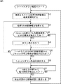
次に、サーバ1によるシャットダウン処理について、図5のフローチャートを参照して説明する。
Next, the shutdown process by the
ただし、前提として、UPS2−1乃至2−iは、全てが稼動状態であって、サーバ1に対して商用交流電源5の電力を供給しており、サーバ1においては、OSが起動されており、かつ、図3に示されたUPS監視部31、UPS制御部32、およびシャットダウン制御部32を実現する所定のプログラムが実行されているものとする。
However, as a premise, the UPSs 2-1 to 2-i are all in an operating state and supply the power of the commercial
ステップS1において、サーバ1の通信部19は、LAN3を介して接続されている各UPS制御装置4とTCP/IPに従って通信を開始する。
In step S1, the
ステップS2において、UPS監視部31は、通信部19およびLAN3を介して接続されている各UPS制御装置4に、それぞれ対応するUPS2の状態の監視を開始させる。これに対応し、各UPS制御装置4がそれぞれ対応するUPS2の状態を示す状態情報(稼動中であるか否か、異常が発生しているか否か、および、異常が発生している場合、UPS2自身の異常であるか商用交流電源5の異常であるかを示す情報)を、LAN3を介してサーバ1のUPS監視部31に随時通知し始めるので、UPS監視部31は、通知された状態情報を取得する。
In step S <b> 2, the
ステップS3において、UPS監視部31は、各UPS制御装置4から随時通知されるUPS2の状態情報に基づき、1台以上のUPS2に「入力電源異常」以外の異常(例えば、バッテリ64の劣化等)が発生したか否かを判定する。1台以上のUPS2に「入力電源異常」以外の異常が発生したと判定された場合、処理はステップS4に進められる。ステップS4において、UPS監視部31は所定のエラー出力を行う。
In step S3, the
具体的には、例えば、発生した異常がUPS2自身の異常(バッテリ64の劣化等)であった場合、UPS監視部31は、異常の内容を示す情報を出力部17に通知する。出力部17は、例えば発生した異常の内容を示すアイコンやポップアップメッセージを画像上に表示したり、異常の内容を示すアラーム音を出力したりすることによってユーザにエラーの発生を提示する。
Specifically, for example, when the abnormality that has occurred is an abnormality of the
なお、ステップS3において、1台以上のUPS2に「入力電源異常」以外の異常が発生していないと判定された場合、ステップS4はスキップされて、処理はステップS5に進められる。
If it is determined in step S3 that no abnormality other than “input power supply abnormality” has occurred in one or
ステップS5において、シャットダウン制御部32は、UPS監視部31を介して(i−n+1)台以上のUPS制御装置4からシャットダウン処理命令が通知されたか否かを判定する。ここで、(i−n+1)台以上のUPS制御装置4からシャットダウン処理命令が通知されていないと判定された場合、サーバ1に商用交流電流5に基づく給電を行うUPS2の数は、少なくともn台存在しているので、サーバ1は引き続き稼動状態を継続することができ、シャットダウン処理を実行する必要がないので、処理はステップS2に戻り、各UPS制御装置4による対応するUPS2の監視と、その監視結果からなる状態情報の通知が継続される。
In step S <b> 5, the
ステップS5において、(i−n+1)台以上のUPS制御装置4からシャットダウン処理命令が通知されたと判定された場合、サーバ1に商用交流電流5に基づく給電を行うことができるUPS2サーバ1の数はn台を下回り、サーバ1は稼動状態を継続することができない。そこで処理はステップS6に進められる。ステップS6において、シャットダウン制御部32は、サーバ1自身のシャットダウン処理を実行する。
In step S5, when it is determined that the shutdown processing command is notified from (i−n + 1) or more
ステップS7において、シャットダウン制御部32は、サーバ1が稼動状態を維持できる電力の給電が復活するまで、すなわち、n台以上のUPS2から電力供給が復活するまで待機する。そして、n台以上のUPS2から電力供給が復活した場合、処理はステップS8に進められる。ステップS8において、シャットダウン制御部32は、サーバ1を休止状態から稼動状態に復旧させる。この後、ステップS1に戻り、それ以降の処理が繰り返されることになる。
In step S <b> 7, the
以上、サーバ1によるシャットダウン処理の説明を終了する。なお、上述した説明は、UPS制御装置4がUPS2の監視結果に基づいてUPS停止処理を実行させる場合の他、ユーザが任意に設定した日時の到来に対応してUPS制御装置4がUPS2にUPS停止処理を実行させる場合や、ユーザの所定の操作に即応してUPS制御装置4がUPS2にUPS停止処理を実行させる場合などにおいて、UPS停止処理を実行に先立って、UPS制御装置4がシャットダウン処理命令をサーバ1に通知する場合にも適用される。
This is the end of the description of the shutdown process by the
以上説明したシャットダウン処理によれば、(i−n+1)台以上のUPS制御装置4からシャットダウン処理命令が通知されない限り、サーバ1の稼動状態を維持することができことになる。
According to the shutdown process described above, the operating state of the
これに対して、(i−n+1)台以上のUPS制御装置4からシャットダウン処理命令が通知された場合、速やかにシャットダウン処理を実行することができ、さらに、n台以上のUPS2からの電源供給が復活した場合、休止状態から稼動状態に自動的に復旧することができる。
On the other hand, when the shutdown process command is notified from (i−n + 1) or more
なお、上述したように、UPS2の停止処理はUPS制御装置4によって制御されるので、この制御にサーバ1のリソースが使用されることはない。したがって、従来のように、サーバが直接的にUPSの停止処理を制御していたときに比較して、サーバの負担を軽減させることができる。
As described above, since the
次に、図6は、サーバ1の出力部17に表示される、シャットダウンおよびUPS停止制御処理に関する各種の設定を入力するための設定画面の表示例を示している。この設定画面100に対するユーザからの入力には、入力部16が用いられる。なお、この設定画面100は、サーバ1にLAN3を介して接続されているUPS制御装置4の数が2台である場合の表示例である。
Next, FIG. 6 shows a display example of a setting screen for inputting various settings related to the shutdown and UPS stop control processing displayed on the
設定画面100の設定欄101は、サーバ1に接続されているUPS制御装置4の機種を選択入力するためのものである。設定欄102は、サーバ1が有する冗長電源機能を有効にするか無効にするかを選択入力するためのものである。設定欄103,104は、接続されている2台のUPS制御装置4それぞれのIPアドレスを入力するためのものである。なお、設定欄103,104には、横に設けられた検索ボタンを押下することにより、LAN3に接続されているUPS制御装置4を検索し、検索されたUPS制御装置4から取得したIPアドレスを自動的に入力させることができる。設定欄105は、UPS2の異常発生などに対応して、その旨をユーザに通知するためのポップアップメッセージ(エラー出力)を表示するか否か選択入力するためのものである。
A setting
設定欄106,107は、2台のUPS制御装置4にそれぞれ接続されているUPS2の出力コンセントを選択入力するためのものである。設定欄108は、LAN3におけるサーバ1の名称を入力するためのものである。設定欄109は、シャットダウン処理命令が所定の数よりも多いと判断された後、サーバ1自身がシャットダウン処理を開始するまでの遅延時間を入力するためのものである。
The setting fields 106 and 107 are used for selectively inputting the output outlets of the
設定欄110は、次に説明する外部コマンドに対応する処理のために設ける時間を入力するためのものである。設定欄111は、シャットダウン処理が実行されるとき、これに先立って実行させる外部コマンドを入力するためのものである。設定欄112は、シャットダウン処理の後、OSを自動的に再起動するか否か、すなわち、サーバ1を休止状態から稼動状態に自動的に復旧させるか否かを選択入力するためのものである。表示113,114には、2台の各UPS制御装置4が、対応するUPS2の給電元を商用交流電源5からバッテリ64に切り替えた後、UPS停止処理を開始するまでの、予め設定されている待機時間が表示される。
The
ユーザは、設定画面100においてサーバ1に関する設定の他、UPS制御装置4およびUPS2に関する設定までも、サーバ1の入力部16および出力部17を用いて設定することができる。
The user can set the settings related to the
次に、本発明を適用した冗長電源機能を有するサーバと当該サーバに対して電力を供給する複数のUPSから成るシステムの他の構成例について、図7乃至図10を参照して説明する。 Next, another configuration example of a system including a server having a redundant power supply function to which the present invention is applied and a plurality of UPSs that supply power to the server will be described with reference to FIGS.
図7は、当該システムの第2の構成例を示している。図1に示された第1の構成例においては、UPS制御装置4−1乃至4−iがそれぞれ1台のUPS2を監視し、制御していたことに対し、この第2の構成例は、1台のUPS制御装置4が複数のUPS2−1乃至2−iを監視し、それぞれを個別に制御するようになされている。さらに、複数のUPS2−1乃至2−iに対応して、サーバ1にシャットダウン処理命令を通知するようになされている。なお、サーバ1、UPS2、およびUPS制御装置4の基本的な構成と動作は、上述した第1の構成例を同様であるので、その説明は省略する。
FIG. 7 shows a second configuration example of the system. In the first configuration example shown in FIG. 1, the UPS control devices 4-1 to 4-i each monitor and control one
図8は、当該システムの第3の構成例を示している。図1に示された第1の構成例においては、UPS制御装置4−1乃至4−iが同一のLAN3を介してサーバ1に接続されていたことに対し、この第3の構成例は、UPS制御装置4−1乃至4−iがそれぞれ異なるLAN3-1乃至3−iを介してサーバ1に接続されている。サーバ1、UPS2、およびUPS制御装置4の基本的な構成と動作は、上述した第1の構成例を同様であるので、その説明は省略する。
FIG. 8 shows a third configuration example of the system. In the first configuration example shown in FIG. 1, the UPS control devices 4-1 to 4-i are connected to the
図9は、当該システムの第4の構成例を示している。この第4の構成例は、図1に示された第1の構成例におけるUPS制御装置4を、UPS2に対して一体的に装着できる拡張カード型回路であるUPS制御カード121に置換したものである。UPS制御カード121には、図4に示されたUPS制御装置4の構成要素である制御部71、監視部72、および通信部73がハードウェアとして実装されている。サーバ1、UPS2、およびUPS制御カード121の基本的な構成と動作は、上述した第1の構成例を同様であるので、その説明は省略する。
FIG. 9 shows a fourth configuration example of the system. This fourth configuration example is obtained by replacing the
図10は、当該システムの第5の構成例を示している。図9に示された第4の構成例においては、UPS制御カード121−1乃至121−iが同一のLAN3を介してサーバ1に接続されていたことに対し、この第5の構成例は、UPS制御カード121−1乃至121−iがそれぞれ異なるLAN3-1乃至3−iを介してサーバ1に接続されている。サーバ1、UPS2、およびUPS制御カード121の基本的な構成と動作は、上述した第1の構成例を同様であるので、その説明は省略する。
FIG. 10 shows a fifth configuration example of the system. In the fourth configuration example shown in FIG. 9, the UPS control cards 121-1 to 121-i are connected to the
以上説明したように、本発明を適用した、冗長電源機能を有するサーバと当該サーバに対して電力を供給する複数のUPSから成るシステムは、サーバ1とUPS制御装置4またはUPS制御カード121を汎用性の高いLAN3で接続することができるので、上述した第1乃至5の構成例の他にもさまざまな変形が可能である。
As described above, a system composed of a server having a redundant power supply function and a plurality of UPSs that supply power to the server to which the present invention is applied uses the
また、サーバ1とUPS制御装置4またはUPS制御カード121を汎用性の高いLAN3で接続していることにより、例えば、サーバ1が故障など何らかの原因によって操作できない場合であっても、新たにパーソナルコンピュータなどをLAN3に接続し、UPS制御装置4またはUPS制御カード121にアクセスすれば、UPS制御装置4またはUPS制御カード121を制御することが可能となる。
Further, since the
なお、本明細書において、プログラムに基づいて実行されるステップは、記載された順序に従って時系列的に行われる処理はもちろん、必ずしも時系列的に処理されなくとも、並列的あるいは個別に実行される処理をも含むものである。 In this specification, the steps executed based on the program are executed in parallel or individually even if they are not necessarily processed in time series, as well as processes executed in time series according to the described order. It also includes processing.
また、プログラムは、1台のコンピュータにより処理されるものであってもよいし、複数のコンピュータによって分散処理されるものであってもよい。さらに、プログラムは、遠方のコンピュータに転送されて実行されるものであってもよい。 The program may be processed by a single computer, or may be distributedly processed by a plurality of computers. Furthermore, the program may be transferred to a remote computer and executed.
また、本明細書において、システムとは、複数の装置により構成される装置全体を表すものである。 Further, in this specification, the system represents the entire apparatus constituted by a plurality of apparatuses.
なお、本発明の実施の形態は、上述した実施の形態に限定されるものではなく、本発明の要旨を逸脱しない範囲において種々の変更が可能である。 The embodiment of the present invention is not limited to the above-described embodiment, and various modifications can be made without departing from the gist of the present invention.
1 サーバ
2 UPS
3 LAN
4 UPS制御装置
5 商用交流電源
11 CPU
21 記録媒体
31 UPS監視部
32 シャットダウン制御部
71 制御部
72 監視部
100 設定画面
121 UPS制御カード
1
3 LAN
4
21
Claims (12)
複数の前記無停電電源装置から供給される電力を電源として動作する情報処理装置の情報処理方法において、
前記無停電電源装置の状態をユーザに提示するための、前記制御装置から前記ネットワークを介して通知された前記無停電電源装置の状態を示す状態情報を取得する第1の取得ステップと、
複数の前記制御装置から前記ネットワークを介して通知され得るシャットダウン処理命令を取得する第2の取得ステップと、
取得された前記シャットダウン処理命令の数に基づいて、前記情報処理装置を稼動状態から休止状態に遷移させる状態遷移ステップと
を含み、
前記制御装置においては、
前記無停電電源装置の状態を監視し、
前記無停電電源装置の監視結果、予め設定されているタイミング、またはユーザからの所定の操作に対応し、前記無停電電源装置の停止処理を制御するとともに、前記情報処理装置に対して稼動状態から休止状態に遷移するように指示するシャットダウン処理命令を生成し、
前記無停電電源装置の監視結果に基づく前記無停電電源装置の状態情報を前記ネットワークを介して前記情報処理装置に通知するとともに、生成された前記シャットダウン処理命令を前記ネットワークを介して前記情報処理装置に通知する
ことを特徴とする情報処理方法。 Comprising a communication means for communicating with a control device for controlling the uninterruptible power supply via a network;
In an information processing method for an information processing apparatus that operates using power supplied from a plurality of uninterruptible power supply apparatuses as a power source,
A first acquisition step of acquiring state information indicating a state of the uninterruptible power supply notified from the control device via the network for presenting a state of the uninterruptible power supply to a user;
A second acquisition step of acquiring a shutdown processing instruction that can be notified from a plurality of the control devices via the network;
Based on the number of acquired the shutdown processing instructions, look including a state transition step for shifting said information processing apparatus to a rest state from the operating state,
In the control device,
Monitoring the state of the uninterruptible power supply,
In response to the monitoring result of the uninterruptible power supply, a preset timing, or a predetermined operation from the user, the stop processing of the uninterruptible power supply is controlled, and the information processing apparatus from the operating state Generate a shutdown processing instruction that instructs to transition to hibernation,
Notifying the information processing apparatus via the network of status information of the uninterruptible power supply based on the monitoring result of the uninterruptible power supply apparatus, and sending the generated shutdown processing command via the network to the information processing apparatus An information processing method characterized by notifying .
ことを特徴とする請求項1に記載の情報処理方法。 The status information includes a first item indicating whether or not the uninterruptible power supply is in operation, a second item indicating whether or not an abnormality has occurred, and an abnormality that has occurred The information processing method according to claim 1, further comprising: a third item indicating whether the power failure power supply itself is abnormal or a commercial AC power supply that is an input power source of the uninterruptible power supply device. .
さらに含むことを特徴とする請求項1に記載の情報処理方法。 The information processing method according to claim 1, further comprising a presentation step of presenting a state of the uninterruptible power supply to a user based on the acquired state information.
さらに含むことを特徴とする請求項1に記載の情報処理方法。 The method further comprises a restoration step of restoring the information processing apparatus to the operating state when power supply from the uninterruptible power supply is restored after the information processing apparatus is transitioned to the hibernation state. The information processing method according to 1.
ことを特徴とする請求項1に記載の情報処理方法。 The information processing method according to claim 1, wherein the communication unit communicates via a network with a single control device that individually controls the plurality of uninterruptible power supply devices.
ことを特徴とする請求項1に記載の情報処理方法。 The information processing method according to claim 1, wherein the communication unit communicates with a plurality of control devices that control one uninterruptible power supply via a network.
前記無停電電源装置を制御する制御装置とネットワークを介して通信する通信手段と、
前記無停電電源装置の状態をユーザに提示するための、前記制御装置から前記ネットワークを介して通知された前記無停電電源装置の状態を示す状態情報を取得するとともに、複数の前記制御装置から前記ネットワークを介して通知され得るシャットダウン処理命令を取得する取得手段と、
取得された前記シャットダウン処理命令の数に基づいて、前記情報処理装置を稼動状態から休止状態に遷移させる状態遷移手段と
を備え、
前記制御装置においては、
前記無停電電源装置の状態を監視し、
前記無停電電源装置の監視結果、予め設定されているタイミング、またはユーザからの所定の操作に対応し、前記無停電電源装置の停止処理を制御するとともに、前記情報処理装置に対して稼動状態から休止状態に遷移するように指示するシャットダウン処理命令を生成し、
前記無停電電源装置の監視結果に基づく前記無停電電源装置の状態情報を前記ネットワークを介して前記情報処理装置に通知するとともに、生成された前記シャットダウン処理命令を前記ネットワークを介して前記情報処理装置に通知する
ことを特徴とする情報処理装置。 In an information processing apparatus that operates using power supplied from a plurality of uninterruptible power supplies as a power source,
Communication means for communicating with the control device for controlling the uninterruptible power supply via a network;
Obtaining state information indicating the state of the uninterruptible power supply notified from the control device via the network for presenting the state of the uninterruptible power supply to the user, and from a plurality of the control devices Obtaining means for obtaining a shutdown processing instruction that can be notified via a network;
State transition means for causing the information processing apparatus to transition from an operating state to a dormant state based on the number of the acquired shutdown processing instructions ,
In the control device,
Monitoring the state of the uninterruptible power supply,
In response to the monitoring result of the uninterruptible power supply, a preset timing, or a predetermined operation from the user, the stop processing of the uninterruptible power supply is controlled, and the information processing apparatus from the operating state Generate a shutdown processing instruction that instructs to transition to hibernation,
Notifying the information processing apparatus via the network of status information of the uninterruptible power supply based on the monitoring result of the uninterruptible power supply apparatus, and sending the generated shutdown processing command via the network to the information processing apparatus Information processing apparatus characterized by notifying
複数の前記無停電電源装置から供給される電力を電源として動作する情報処理装置の制御処理をコンピュータに実行させるプログラムが記録されている記録媒体であって、
前記無停電電源装置の状態をユーザに提示するための、前記制御装置から前記ネットワークを介して通知された前記無停電電源装置の状態を示す状態情報を取得する第1の取得ステップと、
複数の前記制御装置から前記ネットワークを介して通知され得るシャットダウン処理命令を取得する第2の取得ステップと、
取得された前記シャットダウン処理命令の数に基づいて、前記情報処理装置を稼動状態から休止状態に遷移させる状態遷移ステップと
を含み、
前記制御装置においては、
前記無停電電源装置の状態を監視し、
前記無停電電源装置の監視結果、予め設定されているタイミング、またはユーザからの所定の操作に対応し、前記無停電電源装置の停止処理を制御するとともに、前記情報処理装置に対して稼動状態から休止状態に遷移するように指示するシャットダウン処理命令を生成し、
前記無停電電源装置の監視結果に基づく前記無停電電源装置の状態情報を前記ネットワークを介して前記情報処理装置に通知するとともに、生成された前記シャットダウン処理命令を前記ネットワークを介して前記情報処理装置に通知する
処理を情報処理装置のコンピュータに実行させることを特徴とするプログラムが記録されている記録媒体。 Comprising a communication means for communicating with a control device for controlling the uninterruptible power supply via a network;
A recording medium on which a program for causing a computer to execute control processing of an information processing device that operates using power supplied from a plurality of uninterruptible power supply devices as a power source is recorded ,
A first acquisition step of acquiring state information indicating a state of the uninterruptible power supply notified from the control device via the network for presenting a state of the uninterruptible power supply to a user;
A second acquisition step of acquiring a shutdown processing instruction that can be notified from a plurality of the control devices via the network;
Based on the number of acquired the shutdown processing instructions, look including a state transition step for shifting said information processing apparatus to a rest state from the operating state,
In the control device,
Monitoring the state of the uninterruptible power supply,
In response to the monitoring result of the uninterruptible power supply, a preset timing, or a predetermined operation from the user, the stop processing of the uninterruptible power supply is controlled, and the information processing apparatus from the operating state Generate a shutdown processing instruction that instructs to transition to hibernation,
Notifying the information processing apparatus via the network of status information of the uninterruptible power supply based on the monitoring result of the uninterruptible power supply apparatus, and sending the generated shutdown processing command via the network to the information processing apparatus recording medium program for causing executing processing for informing the computer of the information processing apparatus that is recorded in.
複数の前記無停電電源装置から供給される電力を電源として動作する情報処理装置の制御処理をコンピュータに実行させるプログラムであって、
前記無停電電源装置の状態をユーザに提示するための、前記制御装置から前記ネットワークを介して通知された前記無停電電源装置の状態を示す状態情報を取得する第1の取得ステップと、
複数の前記制御装置から前記ネットワークを介して通知され得るシャットダウン処理命令を取得する第2の取得ステップと、
取得された前記シャットダウン処理命令の数に基づいて、前記情報処理装置を稼動状態から休止状態に遷移させる状態遷移ステップと
を含み、
前記制御装置においては、
前記無停電電源装置の状態を監視し、
前記無停電電源装置の監視結果、予め設定されているタイミング、またはユーザからの所定の操作に対応し、前記無停電電源装置の停止処理を制御するとともに、前記情報処理装置に対して稼動状態から休止状態に遷移するように指示するシャットダウン処理命令を生成し、
前記無停電電源装置の監視結果に基づく前記無停電電源装置の状態情報を前記ネットワークを介して前記情報処理装置に通知するとともに、生成された前記シャットダウン処理命令を前記ネットワークを介して前記情報処理装置に通知する
処理を情報処理装置のコンピュータに実行させることを特徴とするプログラム。 Comprising a communication means for communicating with a control device for controlling the uninterruptible power supply via a network;
A program that causes a computer to execute control processing of an information processing device that operates using power supplied from a plurality of uninterruptible power supply devices as a power source,
A first acquisition step of acquiring state information indicating a state of the uninterruptible power supply notified from the control device via the network for presenting a state of the uninterruptible power supply to a user;
A second acquisition step of acquiring a shutdown processing instruction that can be notified from a plurality of the control devices via the network;
Based on the number of acquired the shutdown processing instructions, look including a state transition step for shifting said information processing apparatus to a rest state from the operating state,
In the control device,
Monitoring the state of the uninterruptible power supply,
In response to the monitoring result of the uninterruptible power supply, a preset timing, or a predetermined operation from the user, the stop processing of the uninterruptible power supply is controlled, and the information processing apparatus from the operating state Generate a shutdown processing instruction that instructs to transition to hibernation,
Notifying the information processing apparatus via the network of status information of the uninterruptible power supply based on the monitoring result of the uninterruptible power supply apparatus, and sending the generated shutdown processing command via the network to the information processing apparatus A program for causing a computer of an information processing apparatus to execute a process of notifying a computer.
前記無停電電源装置の状態を監視する監視手段と、
前記無停電電源装置の監視結果、予め設定されているタイミング、またはユーザからの所定の操作に対応し、前記無停電電源装置の停止処理を制御するとともに、前記情報処理装置に対して稼動状態から休止状態に遷移するように指示するシャットダウン処理命令を生成する制御手段と、
前記無停電電源装置の監視結果に基づく前記無停電電源装置の状態情報を前記ネットワークを介して前記情報処理装置に通知するとともに、生成された前記シャットダウン処理命令を前記ネットワークを介して前記情報処理装置に通知する通知手段と
を備えることを特徴とする制御装置。 In a control device that controls an uninterruptible power supply that supplies power to an information processing device,
Monitoring means for monitoring the state of the uninterruptible power supply;
In response to the monitoring result of the uninterruptible power supply , a preset timing, or a predetermined operation from the user, the stop processing of the uninterruptible power supply is controlled , and the information processing apparatus from the operating state Control means for generating a shutdown processing instruction for instructing transition to a dormant state;
Notifying the information processing apparatus via the network of status information of the uninterruptible power supply based on the monitoring result of the uninterruptible power supply apparatus, and sending the generated shutdown processing command via the network to the information processing apparatus And a notification means for notifying to the control device.
ことを特徴とする請求項10に記載の制御装置。 The status information includes a first item indicating whether or not the uninterruptible power supply is in operation, a second item indicating whether or not an abnormality has occurred, and an abnormality that has occurred The control device according to claim 10 , further comprising: a third item indicating whether the power failure power supply itself is abnormal or a commercial AC power supply that is an input power source of the uninterruptible power supply device.
ことを特徴とする請求項10に記載の制御装置。 As the uninterruptible power supply stop process , the control means supplies the power supplied to the information processing apparatus from a commercial AC power source that is an input power source of the uninterruptible power supply to the uninterruptible power supply. after allowing switching to a built-in battery, the uninterruptible power supply from the operating state to supply power to the information processing apparatus, according to claim 10, characterized in that to transition to a stop state where no electric power is supplied Control device.
Priority Applications (1)
| Application Number | Priority Date | Filing Date | Title |
|---|---|---|---|
| JP2006324483A JP4915224B2 (en) | 2006-11-30 | 2006-11-30 | Information processing method, information processing apparatus, recording medium, program, and control apparatus |
Applications Claiming Priority (1)
| Application Number | Priority Date | Filing Date | Title |
|---|---|---|---|
| JP2006324483A JP4915224B2 (en) | 2006-11-30 | 2006-11-30 | Information processing method, information processing apparatus, recording medium, program, and control apparatus |
Publications (2)
| Publication Number | Publication Date |
|---|---|
| JP2008140029A JP2008140029A (en) | 2008-06-19 |
| JP4915224B2 true JP4915224B2 (en) | 2012-04-11 |
Family
ID=39601438
Family Applications (1)
| Application Number | Title | Priority Date | Filing Date |
|---|---|---|---|
| JP2006324483A Active JP4915224B2 (en) | 2006-11-30 | 2006-11-30 | Information processing method, information processing apparatus, recording medium, program, and control apparatus |
Country Status (1)
| Country | Link |
|---|---|
| JP (1) | JP4915224B2 (en) |
Families Citing this family (9)
| Publication number | Priority date | Publication date | Assignee | Title |
|---|---|---|---|---|
| KR100907947B1 (en) | 2009-03-05 | 2009-07-16 | (주)동현기술사사무소 | Uninterruptable power supply for server |
| JP2014059704A (en) * | 2012-09-18 | 2014-04-03 | Nec Engineering Ltd | Power supply control system of information processor and power supply control method of information processor |
| US10418849B2 (en) | 2014-03-28 | 2019-09-17 | Schneider Electric It Corporation | Systems and methods for monitoring a configuration of UPS groups with different redundancy levels |
| JP6725872B2 (en) * | 2016-03-17 | 2020-07-22 | 日本電気株式会社 | Server device, power supply control method, program, external power supply device, server system |
| US10671139B2 (en) * | 2017-05-31 | 2020-06-02 | Quanta Computer Inc. | Operable server system when standby power of PSU fails |
| JP7276526B2 (en) * | 2019-11-29 | 2023-05-18 | オムロン株式会社 | Information processing device, management program, management method, and information processing system |
| JP7063315B2 (en) * | 2019-11-29 | 2022-05-09 | オムロン株式会社 | Information processing equipment, management programs, management methods, and information processing systems |
| JP7276566B2 (en) * | 2022-01-20 | 2023-05-18 | オムロン株式会社 | Information processing system, information processing device, management program, and management method |
| JP7207595B2 (en) * | 2022-01-20 | 2023-01-18 | オムロン株式会社 | Information processing device, management program, management method, and information processing system |
Family Cites Families (6)
| Publication number | Priority date | Publication date | Assignee | Title |
|---|---|---|---|---|
| JP3061080B2 (en) * | 1992-02-21 | 2000-07-10 | 横河電機株式会社 | Process monitoring device |
| JP2002073221A (en) * | 2000-08-30 | 2002-03-12 | Arufatekku Kk | Uninteruptible power supply system |
| JP2002136000A (en) * | 2000-10-25 | 2002-05-10 | Arufatekku Kk | Uninterruptible power supply system |
| JP2003131764A (en) * | 2001-10-29 | 2003-05-09 | Densei Lambda Kk | Ups system-monitoring program and ups system-monitoring method |
| JP3711559B2 (en) * | 2003-08-08 | 2005-11-02 | オムロン株式会社 | Information processing apparatus and method, recording medium, and program |
| JP2005137136A (en) * | 2003-10-30 | 2005-05-26 | Fuji Electric Fa Components & Systems Co Ltd | Management system for uninterruptible power supply |
-
2006
- 2006-11-30 JP JP2006324483A patent/JP4915224B2/en active Active
Also Published As
| Publication number | Publication date |
|---|---|
| JP2008140029A (en) | 2008-06-19 |
Similar Documents
| Publication | Publication Date | Title |
|---|---|---|
| JP4915224B2 (en) | Information processing method, information processing apparatus, recording medium, program, and control apparatus | |
| JP3711559B2 (en) | Information processing apparatus and method, recording medium, and program | |
| JP5560737B2 (en) | Power supply system, electronic apparatus, and control method for power supply system | |
| JP4173942B2 (en) | Backup power supply module, backup power supply device and computer | |
| JP2001178018A (en) | Power supply controller, method of controlling power supply, and storage medium | |
| JP3711557B2 (en) | Information processing apparatus and method, recording medium, and program | |
| US20130326237A1 (en) | Uninterruptable pc power unit for use in personal computer and servers | |
| US7045914B2 (en) | System and method for automatically providing continuous power supply via standby uninterrupted power supplies | |
| US20180233947A1 (en) | Device operating state modification with uninterruptible power source | |
| US20040073817A1 (en) | Method for automatically saving in-process programs before shutdown | |
| JP5549535B2 (en) | Information processing apparatus, control method, and control apparatus | |
| JP5884268B2 (en) | Stop control system for uninterruptible power supply | |
| JP4543328B2 (en) | Information processing device, uninterruptible power supply, power supply method, recording medium, and program | |
| JP4304624B2 (en) | Information processing device, uninterruptible power supply, power supply method, recording medium, and program | |
| JP2010073030A (en) | Electronic apparatus and end processing program | |
| JP2011254660A (en) | Electrical power system | |
| JP5174093B2 (en) | Electronic device and control program thereof | |
| JP2007124783A (en) | Uninterruptible power supply device and battery unit | |
| CN111381659B (en) | Computer system and power management method | |
| JP2011039685A (en) | Information processor and control program thereof | |
| TWI685733B (en) | Computer system and power management method | |
| JP6738035B1 (en) | Information processing device and program | |
| JP4987450B2 (en) | Image forming apparatus | |
| CN106020406B (en) | Control method, connector and electronic equipment | |
| JP2002297270A (en) | Information processor |
Legal Events
| Date | Code | Title | Description |
|---|---|---|---|
| A621 | Written request for application examination |
Free format text: JAPANESE INTERMEDIATE CODE: A621 Effective date: 20090907 |
|
| A977 | Report on retrieval |
Free format text: JAPANESE INTERMEDIATE CODE: A971007 Effective date: 20110127 |
|
| A131 | Notification of reasons for refusal |
Free format text: JAPANESE INTERMEDIATE CODE: A131 Effective date: 20110201 |
|
| A02 | Decision of refusal |
Free format text: JAPANESE INTERMEDIATE CODE: A02 Effective date: 20111004 |
|
| A521 | Written amendment |
Free format text: JAPANESE INTERMEDIATE CODE: A523 Effective date: 20111118 |
|
| A911 | Transfer of reconsideration by examiner before appeal (zenchi) |
Free format text: JAPANESE INTERMEDIATE CODE: A911 Effective date: 20111205 |
|
| TRDD | Decision of grant or rejection written | ||
| A01 | Written decision to grant a patent or to grant a registration (utility model) |
Free format text: JAPANESE INTERMEDIATE CODE: A01 Effective date: 20111227 |
|
| A01 | Written decision to grant a patent or to grant a registration (utility model) |
Free format text: JAPANESE INTERMEDIATE CODE: A01 |
|
| A61 | First payment of annual fees (during grant procedure) |
Free format text: JAPANESE INTERMEDIATE CODE: A61 Effective date: 20120109 |
|
| FPAY | Renewal fee payment (event date is renewal date of database) |
Free format text: PAYMENT UNTIL: 20150203 Year of fee payment: 3 |
|
| R150 | Certificate of patent or registration of utility model |
Ref document number: 4915224 Country of ref document: JP Free format text: JAPANESE INTERMEDIATE CODE: R150 Free format text: JAPANESE INTERMEDIATE CODE: R150 |