JP4913873B2 - Electronic pen system and electronic pen - Google Patents
Electronic pen system and electronic pen Download PDFInfo
- Publication number
- JP4913873B2 JP4913873B2 JP2010004125A JP2010004125A JP4913873B2 JP 4913873 B2 JP4913873 B2 JP 4913873B2 JP 2010004125 A JP2010004125 A JP 2010004125A JP 2010004125 A JP2010004125 A JP 2010004125A JP 4913873 B2 JP4913873 B2 JP 4913873B2
- Authority
- JP
- Japan
- Prior art keywords
- pen
- electronic pen
- touch
- information
- electronic
- Prior art date
- Legal status (The legal status is an assumption and is not a legal conclusion. Google has not performed a legal analysis and makes no representation as to the accuracy of the status listed.)
- Active
Links
Images


Description
本発明は、タッチパネルのタッチ面に対する複数の電子ペンによるタッチ操作に応じた画像をタッチ面に表示させる電子ペンシステム及び電子ペンに関するものである。 The present invention relates to an electronic pen system and an electronic pen that display images on a touch surface according to touch operations with a plurality of electronic pens on a touch surface of a touch panel.
電子ペンとタッチパネルとを組み合わせた電子ペンシステムが知られている。この種の電子ペンシステムは、パソコンや携帯情報端末の分野で広く普及しているが、タッチパネルを大画面の表示装置と組み合わせることで、多人数を対象にしたプレゼンテーションや講義で使用することができるようにした、いわゆるインタラクティブホワイトボード(電子黒板)として用いる技術が知られている(特許文献1参照)。 There is known an electronic pen system in which an electronic pen and a touch panel are combined. This type of electronic pen system is widely used in the field of personal computers and personal digital assistants, but can be used in presentations and lectures for a large number of people by combining a touch panel with a large-screen display device. The technique used as what is called an interactive whiteboard (electronic blackboard) is known (refer patent document 1).
このような大型の電子ペンシステムにおいては、描画色などの属性(機能)の異なる複数の電子ペンを使い分けて使用したり、複数のユーザーが各人に与えられた電子ペンを用いて描画などの所要の操作を行うことができるようにすると、使い勝手が良くなる。 In such a large-sized electronic pen system, a plurality of electronic pens having different attributes (functions) such as a drawing color can be used properly, or a plurality of users can perform drawing using an electronic pen given to each person. When the required operation can be performed, the usability is improved.
このような要望に関連して、従来、ユーザが必要に応じて電子ペンの属性を変更することができるようにした技術が知られている(特許文献1参照)。また、異なる属性が割り振られた複数の電子ペンを同時に使用することができるようにした技術が知られている(特許文献2参照)。 In relation to such a request, conventionally, a technique is known in which a user can change an attribute of an electronic pen as needed (see Patent Document 1). Also, a technique is known in which a plurality of electronic pens assigned different attributes can be used simultaneously (see Patent Document 2 ).
しかるに、前記特許文献1に開示された従来の技術では、属性(描画色)の設定が、タッチパネル上のアイコンを指でタッチすることで行なわれるため、インキを充填したマーカーを用いる一般的なホワイトボードと使用感が大きく異なり、また、電子ペン自体に属性を指定する手段がないため、使い勝手が悪いという問題がある。
However, in the conventional technique disclosed in
また、前記特許文献2に開示された従来の技術では、複数の電子ペンの各々に特定の周波数を割り当ててその周波数で電子ペンを判別するようにしており、複数の電子ペンを使い分けることができるものの、各々の電子ペンの属性を切り替えて使用することができない。つまり、ある電子ペンは黒色、別の電子ペンは赤色というように、予め定められた固有の属性が電子ペンに与えられており、この属性をユーザが必要に応じて適宜に変更することができない。このため、属性の異なる多数の電子ペンが必要となり、また、複数のユーザが手持ちの電子ペンを好みの属性に設定して使用することができず、不便である。
In the prior art disclosed in
本発明は、このような従来技術の問題点を解消するべく案出されたものであり、その主な目的は、複数の電子ペンの各々をユーザが必要に応じて属性を切り替えて使用することができるように構成された電子ペンシステムを提供することにある。 The present invention has been devised to solve such problems of the prior art, and its main purpose is that the user uses each of a plurality of electronic pens by switching attributes as necessary. To provide an electronic pen system configured to be able to
本発明の電子ペンシステムは、複数の電子ペンと、この電子ペンによるタッチ操作が行われるタッチ面を備えたタッチパネル体と、前記タッチ面上での前記電子ペンのタッチ位置を検出する位置検出装置と、前記タッチ面を表示画面として所要の画像を表示する表示装置と、前記位置検出装置から取得した位置検出情報に応じた画像を前記表示装置に表示させる制御装置と、を備えた電子ペンシステムであって、前記電子ペンは、属性をユーザにより選択させる属性選択手段と、この属性選択手段により選択された属性情報及び自身の識別情報を付加したペン情報を前記制御装置に送信するペン情報送信手段と、前記タッチ面に対するタッチ状態を検出するタッチ状態検出手段と、を備え、前記タッチ状態検出手段がタッチ状態を検出するのに応じて前記ペン情報送信手段から前記制御装置に前記ペン情報を送信した後に、前記電子ペンのペン先部を導通させて前記位置検出装置によるタッチ位置の検出を可能とし、前記制御装置は、前記電子ペンから前記ペン情報を受信した後、一定時間内に前記位置検出装置からタッチ位置を受信した場合には、前記ペン情報に付加された識別情報を有する電子ペンによるタッチ操作と判断し、当該ペン情報に含まれる属性情報に応じた画像を前記表示装置に表示させる構成とする。 An electronic pen system of the present invention includes a plurality of electronic pens, a touch panel body including a touch surface on which a touch operation is performed by the electronic pen, and a position detection device that detects a touch position of the electronic pen on the touch surface. An electronic pen system comprising: a display device that displays a required image using the touch surface as a display screen; and a control device that causes the display device to display an image according to position detection information acquired from the position detection device. The electronic pen transmits an attribute selection means for selecting an attribute by a user, and pen information transmission for transmitting pen information to which the attribute information selected by the attribute selection means and its identification information are added to the control device. Means and a touch state detection means for detecting a touch state on the touch surface, wherein the touch state detection means detects the touch state. After transmitting the pen information from the pen information transmitting means to the control device according to the then by the position detecting device by conducting the pen tip portion of the electronic pen and allow detection of the touch position, the control device, the When the touch position is received from the position detection device within a predetermined time after receiving the pen information from the electronic pen, it is determined that the touch operation is performed by the electronic pen having the identification information added to the pen information. An image according to the attribute information included in the pen information is configured to be displayed on the display device.
本発明によれば、複数の電子ペンの各々をユーザが必要に応じて属性を切り替えて使用することができる。 According to the present invention, the user can use each of the plurality of electronic pens by switching attributes as necessary.
上記課題を解決するためになされた第1の発明は、複数の電子ペンと、この電子ペンによるタッチ操作が行われるタッチ面を備えたタッチパネル体と、前記タッチ面上での前記電子ペンのタッチ位置を検出する位置検出装置と、前記タッチ面を表示画面として所要の画像を表示する表示装置と、前記位置検出装置から取得した位置検出情報に応じた画像を前記表示装置に表示させる制御装置と、を備えた電子ペンシステムであって、前記電子ペンは、属性をユーザにより選択させる属性選択手段と、この属性選択手段により選択された属性情報及び自身の識別情報を付加したペン情報を前記制御装置に送信するペン情報送信手段と、前記タッチ面に対するタッチ状態を検出するタッチ状態検出手段と、を備え、前記タッチ状態検出手段がタッチ状態を検出するのに応じて前記ペン情報送信手段から前記制御装置に前記ペン情報を送信した後に、前記電子ペンのペン先部を導通させて前記位置検出装置によるタッチ位置の検出を可能とし、前記制御装置は、前記電子ペンから前記ペン情報を受信した後、一定時間内に前記位置検出装置からタッチ位置を受信した場合には、前記ペン情報に付加された識別情報を有する電子ペンによるタッチ操作と判断し、当該ペン情報に含まれる属性情報に応じた画像を前記表示装置に表示させる構成とする。 A first invention made to solve the above problems is a touch panel body including a plurality of electronic pens, a touch surface on which a touch operation is performed by the electronic pens, and a touch of the electronic pen on the touch surface. A position detection device for detecting a position; a display device for displaying a required image using the touch surface as a display screen; and a control device for causing the display device to display an image according to position detection information acquired from the position detection device; an electronic pen system wherein the electronic pen, the attribute selection means for selecting an attribute by a user, the control pens information added attribute information and its own identification information selected by the attribute selection means includes a pen information transmitting means for transmitting device, and a touch state detection means for detecting a touch state of the touch surface, the touch state detecting means touch From the pen information transmitting means in response to detecting a state after transmitting the pen information to the control device, wherein by conducting the pen tip portion of the electronic pen to allow detection of the touch position by the position detecting device, When the control device receives a touch position from the position detection device within a predetermined time after receiving the pen information from the electronic pen, the control device touches with the electronic pen having identification information added to the pen information. It is determined that the operation is performed, and an image corresponding to the attribute information included in the pen information is displayed on the display device.
これによると、複数の電子ペンの各々をユーザが必要に応じて属性を適宜に切り替えて使用することができる。 According to this, each of the plurality of electronic pens can be used by appropriately switching the attribute as required by the user.
また、タッチ操作を行った指示物がいずれの電子ペンであるかを間違いなく判別することができる。 Further , it is possible to definitely determine which electronic pen is the pointing object that has performed the touch operation.
前記課題を解決するためになされた第2の発明は、前記第1の発明において、前記制御装置は、以前に描画された画像に重なり合うように新たな画像が描画される場合に、以前に描画された画像と新たに描画される画像との重複部分を、予め指定された描画規則に基づいて描画する描画制御手段を備え、前記電子ペンは、前記描画規則をユーザに指定させる描画規則指定手段を備え、この描画規則指定手段で指定された描画規則に関する情報を前記制御装置に送信する構成とする。 A second invention made to solve the above problem is that, in the first invention, the control device draws a previous image when a new image is drawn so as to overlap the previously drawn image. A drawing control means for drawing an overlapping portion between the image to be newly drawn and an image to be newly drawn based on a drawing rule designated in advance, and the electronic pen allows the user to designate the drawing rule. The information regarding the drawing rule designated by the drawing rule designating means is transmitted to the control device.
これによると、ユーザが電子ペンで描画規則を指定することができる。 According to this, the user can specify a drawing rule with the electronic pen.
前記課題を解決するためになされた第3の発明は、前記第1又は第2の発明において、前記描画規則は、以前に描画された画像と新たに描画される画像との重複部分を、新たな画像の描画条件にしたがって描画する上書き処理に関するものである構成とする。 According to a third aspect of the present invention for solving the above-described problems, in the first or second aspect of the present invention, the drawing rule includes a new overlapping portion between an image drawn before and a newly drawn image. The configuration relates to an overwriting process for drawing according to the drawing conditions of a simple image.
前記課題を解決するためになされた第4の発明は、前記第1〜第3の発明において、前記描画規則は、以前に描画された画像と新たに描画される画像との重複部分を、両者の描画条件を指定の比率により変更した描画条件で描画する重ね合わせ処理に関するものである構成とする。
前記課題を解決するためになされた第5の発明は、複数の電子ペンによるタッチ操作が行われるタッチ面を表示画面とし、前記タッチ面上での前記電子ペンのタッチ位置及び前記電子ペンの属性に応じた画像を前記表示画面に表示させる制御装置と通信を行う電子ペンであって、前記電子ペンの属性をユーザにより選択させる属性選択手段と、この属性選択手段により選択された属性及び自身の識別情報を付加したペン情報を前記制御装置に送信するペン情報送信手段と、前記タッチ面に対するタッチ状態を検出するタッチ状態検出手段と、を備え、前記タッチ状態検出手段がタッチ状態を検出するのに応じて前記ペン情報送信手段から前記制御装置に前記ペン情報を送信した後に、前記電子ペンのペン先部を導通させてタッチ位置の検出を可能とする構成とする。
これによると、複数の電子ペンの各々をユーザが必要に応じて属性を適宜に切り替えて使用することができる。
According to a fourth aspect of the present invention for solving the above-described problems, in the first to third aspects of the present invention, the drawing rule includes an overlapping portion between an image drawn before and a newly drawn image. The drawing condition is related to the superimposition processing for drawing with the drawing condition changed by the specified ratio.
According to a fifth aspect of the present invention for solving the above problems, a touch surface on which a touch operation with a plurality of electronic pens is performed is a display screen, and the touch position of the electronic pen on the touch surface and the attributes of the electronic pen An electronic pen that communicates with a control device that displays an image in accordance with the display screen, attribute selecting means for selecting an attribute of the electronic pen by a user, the attribute selected by the attribute selecting means, and the own Pen information transmitting means for transmitting pen information to which identification information is added to the control device, and touch state detecting means for detecting a touch state on the touch surface, wherein the touch state detecting means detects the touch state. In response to the pen information transmission means, the pen information is transmitted to the control device, and then the pen tip portion of the electronic pen is turned on to detect the touch position. A configuration in which the function.
According to this, each of the plurality of electronic pens can be used by appropriately switching the attribute as required by the user.
以下、本発明の実施の形態を、図面を参照しながら説明する。 Hereinafter, embodiments of the present invention will be described with reference to the drawings.
図1は、本発明による電子ペンシステムを示す全体構成図である。この電子ペンシステムは、電子ペン1と、この電子ペン1や指Fによるタッチ操作が行われるタッチ面2を備えたタッチパネル体3と、タッチ面2に対する導電体の接近または接触に応じた静電容量の変化からタッチ位置を検出する位置検出装置4と、タッチ面2を表示画面として所要の画像を表示する表示装置5と、位置検出装置4から取得した位置検出情報及び電子ペン1の属性に応じた画像を表示装置5に表示させる制御装置6と、を備えている。
FIG. 1 is an overall configuration diagram showing an electronic pen system according to the present invention. The electronic pen system includes an
タッチパネル体3には、互いに並走する複数の送信電極(第1電極)11と、この送信電極11と絶縁され互いに並走する複数の受信電極(第2電極)12とが格子状に配置されている。送信電極11と受信電極12の絶縁状態は、例えばこれらの間にシート状の支持体を設けることで達成される。
The
位置検出装置4は、送信電極11に対して駆動信号(パルス信号)を印加する送信部13と、送信電極11に印加された駆動信号に応答した受信電極12の充放電電流信号を受信して、送信電極11と受信電極12とが交差(絶縁状態で重畳)する電極交点ごとのレベル信号を出力する受信部14と、この受信部14から出力されるレベル信号に基づいてタッチ位置を検出すると共に送信部13及び受信部14の動作を制御する位置検出制御部15とを備えている。
The
タッチパネル体3は、大画面の表示装置5と組み合わせることで、プレゼンテーションや講義に用いることができるようにした、いわゆるインタラクティブホワイトボードとして用いられ、特にここでは、表示装置5がプロジェクタであり、タッチ面2がプロジェクタ用のスクリーンとなる。この他、表示装置5を、液晶ディスプレイやプラズマディスプレイで構成し、いずれも透明材料で構成されたタッチパネル体、送信電極及び受信電極の背面側に配置するようにしてもよい。
The
制御装置6は、電子ペン1との間で通信を行う無線通信部16と、タッチ面2に対する電子ペン1や指Fによるタッチ操作に応じて位置検出装置4から出力される位置検出情報に基づいて文字、線及び図形などの画像を描画する描画制御部17と、描画制御部17の出力に基づいて表示画面データを生成して表示装置5に出力する表示制御部18と、これら各部を総括的に制御する主制御部19と、を備えている。
The
描画制御部17では、描画モードでタッチ操作に応じて画像を描画し、イレーサーモードではタッチ操作に応じて画像を消去する処理が行われる。また、この描画制御部17には、位置検出装置4から位置検出情報を取得した際に、その位置検出情報が電子ペン1及び指Fのいずれによるものかを判別する指示物判別部(指示物判別手段)を備えており、電子ペン1及び指Fにそれぞれ設定された属性に基づいて描画処理が行われる。
The
主制御部19では、カーソル操作モードで表示画面に表示された操作ボタンに割り当てられた処理をタッチ操作に応じて実行する。この制御装置6は、パソコン及び周辺機器で構成され、主制御部19を実現するOS及び描画制御部17を実現するアプリケーションプログラムが導入される。
The
送信電極11及び受信電極12は同一の配置ピッチ(例えば10mm)で配置されており、その送信電極11と受信電極12とが交差する電極交点にはコンデンサが形成され、ユーザが指示物でタッチ操作を行うと、これに応じて電極交点の静電容量が実質的に減少することで、タッチ操作の有無を検出することができる。
The
特にここでは、相互容量方式が採用され、送信電極11に駆動信号を印加すると、これに応答して受信電極12に充放電電流が流れ、このとき、ユーザのタッチ操作に応じて電極交点の静電容量が変化すると、受信電極12の充放電電流が変化し、この充放電電流の変化量を受信部14で電極交点ごとのレベル信号(ディジタル信号)に変換して位置検出制御部15に出力し、位置検出制御部15では、電極交点ごとのレベル信号に基づいてタッチ位置が算出される。この相互容量方式では、同時に複数のタッチ位置を検出する、いわゆるマルチタッチ(多点検出)が可能である。
In particular, here, the mutual capacitance method is adopted, and when a drive signal is applied to the
送信部13は、位置検出制御部15から出力されるタイミング信号に同期して、送信電極11を1本ずつ選択して駆動信号を印加する。受信部14は、1本の送信電極11に駆動信号を印加する間に、受信電極12を1本ずつ選択して受信電極12の充放電電流を受信する。これにより、全ての電極交点ごとの充放電電流を取り出すことができる。
The transmission unit 13 selects the
位置検出制御部15は、受信部14から出力される電極交点ごとのレベル信号から所定の演算処理によってタッチ位置(タッチ領域の中心座標)を求める。このタッチ位置の演算では、X軸方向(送信電極11の延在方向)とY軸方向(受信電極12の延在方向)とでそれぞれ隣接する複数(例えば4×4)の電極交点ごとのレベル信号から所要の補間法(例えば重心法)を用いてタッチ位置を求める。これにより、送信電極11及び受信電極12の配置ピッチ(10mm)より高い分解能(例えば1mm以下)でタッチ位置を検出することができる。
The position
図2は、図1に示した電子ペン1の概略構成図である。この電子ペン1は、ユーザが手で握る把持部21を備えたペン本体22と、タッチ操作時にタッチ面2に押し当てられるペン先部23と、制御装置6との間で通信を行う無線通信回路24と、互いに電気的に遮断された状態で設けられたペン先部23と把持部21との電気的接続を断続する接続スイッチ25と、タッチ面に対するタッチ状態を検出する磁気センサー(タッチ状態検出手段)26と、各部の動作を総括的に制御するペン制御回路27と、を備えている。また、ペン制御回路27や無線通信回路24などには必要に応じて電源回路28を介して電池29の電力が供給される。なお、本実施形態においては、把持部21は導電性樹脂で構成しているが、金属材料や樹脂に導電性材料をコーティングしたものであってもよく、ユーザが電子ペン1を把持したときに、少なくともペン先部23と人体が電気的に導通するよう、導電性材料を適宜選択すればよい。
FIG. 2 is a schematic configuration diagram of the
ペン本体22は導電性の合成樹脂材からなる。ペン先部23はペン先カバー31とペン先軸32とからなる。ペン先カバー31は導電性のフェルト材からなり、ペン先軸32は導電性の合成樹脂材からなる。ペン先部23は、絶縁体33を介してペン本体22に保持されている。ペン先軸32は、軸方向に移動可能に図示しないガイド部材に支持されている。タッチ操作時にペン先部23をタッチ面2に押し当てると、フェルト材からなるペン先カバー31が縮んでペン先軸32が押し込まれる。
The
磁気センサー26は、ペン先軸32に設けられた磁石34の変位を検出する。タッチ操作時にペン先軸32が押し込まれると、このペン先軸32の移動に伴って磁石34と磁気センサー26との距離が変化することで、タッチ状態を検出することができる。
The
接続スイッチ25は電子スイッチ(FETなどのトランジスタ)であり、ペン制御回路(スイッチ制御手段)27によりオンオフ制御される。なお、電子スイッチは、オフ時の端子間寄生容量が小さいことが好適である。容量成分が大きいと接続スイッチ25がオフであっても、人体に導通したのと同等の状態となるからである。この観点から、接続スイッチ25は静電容量が殆ど無視できる接点式リレーで構成してもよい。
The
ここで、接続スイッチ25がオフの場合、ペン先部23は把持部21と電気的に遮断されている。ペン先部23の成分容量は極めて小さいため、ペン先部23をタッチ面2に近接させても(あるいは軽く触れた状態では)、位置検出装置4は電子ペン1の近接・当接を認識することはない。
Here, when the
一方、接続スイッチ25がオンになると、ペン先部23は把持部21と電気的に接続され、人体は把持部21を介してペン先部23と導通する。人体は比較的大きな静電容量を有するため、電子ペン1がタッチ面2に近接・接触すると、送信電極11、受信電極12(図1参照)間の電気力線が変化して、位置検出装置4は電子ペン1のタッチ状態を確実に検出できる。
On the other hand, when the
電子ペン1には、プッシュ式の操作スイッチ41〜43と、ロータリー式の操作スイッチ44が設けられている。プッシュ式の操作スイッチ41〜43は、操作ボタン45〜47を押下操作することで、各操作スイッチ41〜43に割り当てられた動作をペン制御回路27に実行させる。例えば第1の操作スイッチ41には、マウスのボタンと同様の機能が与えられ、第2・第3の操作スイッチ42・43には、表示画面を送り方向及び戻り方向にスクロールさせる機能が与えられる。
The
ロータリー式の操作スイッチ(属性選択手段)44は、操作つまみ48を回転操作することで、電子ペン1の機能に関する属性が切り替えられる。特にここでは、操作スイッチ44により、描画モードでの黒、赤、緑及び青の描画色、及びイレーサーモードを選択することができる。なお、この他の機能に関する属性を選択可能な構成としてもよい。
The rotary operation switch (attribute selection means) 44 is configured to switch the attribute relating to the function of the
ペン制御回路27は、固有のペン識別情報(ID)を記憶する。また、ペン制御回路27は、磁気センサー26の出力に基づいてタッチ状態か否かを判別してステータス情報を生成し、また、操作スイッチ44の操作に応じて属性情報を生成し、ペン制御回路27からの送信指示に応じて無線通信回路24(ペン情報送信手段)から制御装置6に、ペン識別情報、ステータス情報、及び属性情報を含むペン情報が送信される。無線通信回路24は、例えば2.4GHz帯高度化小電力データ通信が採用される。
The
図3は、図1に示した電子ペン1と制御装置6の処理の手順を示すフロー図である。電子ペン1は、ユーザがタッチ操作を行い、ペン先部23がタッチ面2に押し当てられて、磁気センサー26がタッチ状態を検出するのに応じて(ST102でYes)、無線通信回路24からペン情報を制御装置6に送信した後(ST103)、接続スイッチ25をオンとしてペン入力可能状態となるようにする(ST105)。
FIG. 3 is a flowchart showing a processing procedure of the
制御装置6は、電子ペン1からのペン情報を受信した後に(ST202でYes)、位置検出装置4からの位置検出情報を受信した場合に(ST206でYes)、その位置検出情報を電子ペン1によるタッチ操作と判断してペン入力処理に進む(ST208)。一方、電子ペン1からのペン情報を受信することなく位置検出装置4からの位置検出情報を受信した場合には、指Fによるタッチ操作と判断して指入力処理に進む(ST209)。
After receiving the pen information from the electronic pen 1 (Yes in ST202), the
電子ペン1では、磁気センサー26によりタッチ状態が検出されてから所定時間(例えば500ms)経過した後に(ST104)、接続スイッチ25をオンとする。これにより、制御装置6において電子ペンからのペン情報を受信するタイミングと、ペン入力可能状態となって位置検出装置4からの位置検出情報を受信するタイミングとが逆になることを確実に避けることができる。
In the
また、電子ペン1では、磁気センサー26により検出される非タッチ状態が所定時間(例えば2sec)継続したところで(ST107でYes)、接続スイッチ25をオフとする。これにより、ユーザがタッチ操作を行うのに応じてペン情報の送信及び接続スイッチ25のオン操作が頻繁に繰り返されることを避けることができる。
Further, in the
また、ここでは、電子ペン1が起動されるとまずペン識別情報を含むペン情報が制御装置6に送信される(ST101)。制御装置6では、電子ペン1からの起動時のペン情報を受信することで(ST201)、使用中の電子ペン1を認識することができる。
Further, here, when the
なお、例えば第1の操作スイッチ41の押下により、ペン識別情報、ステータス情報、及び属性情報を含むペン情報を任意のタイミングで制御装置6に送信することができるようにしてもよい。制御装置6では、ペン情報を電子ペン1から受信すると、表示装置5によりタッチ面2上に電子ペン1の属性、例えば描画モードでの描画色を表示させる。これにより、電子ペン1に設定された属性をユーザが適宜に認識することができる。
Note that, for example, pen information including pen identification information, status information, and attribute information may be transmitted to the
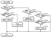
図4は、図3に示したペン入力処理の手順を示すフロー図である。まず、ペン情報の属性がマーカーとなっている場合には(ST301でYes)、座標位置に指定の色で描画する処理が行われる(ST302)。一方、ペン情報の属性がイレーサーとなっている場合に(ST303でYes)、座標位置に描画データがあれば(ST304でYes)、その描画データを消去する処理が行われる(ST305)。 FIG. 4 is a flowchart showing a procedure of the pen input process shown in FIG. First, when the pen information attribute is a marker (Yes in ST301), a process of drawing with a specified color at a coordinate position is performed (ST302). On the other hand, when the attribute of the pen information is an eraser (Yes in ST303), if there is drawing data at the coordinate position (Yes in ST304), processing for deleting the drawing data is performed (ST305).
図5は、図1に示した表示装置5によりタッチ面2上に表示される描画パレットを示す図である。指入力では、描画パレットにより入力属性が選択される。ここでは、矢印(カーソル)、黒、赤、青及び緑の各色のマーカー、イレーサー、特殊マーカー、並びに特殊機能の各選択ボックスが表示され、これを指Fでタッチ操作することで選択される。特殊マーカー及び特殊機能を選択すると、具体的な機能を選択するサブメニューが表示される。特殊マーカーは、蛍光マーカー、任意の図形を並べて線を描く機能などである。特殊機能は、表示画面を部分的に拡大するルーペ機能、表示画面の一部を残して暗くするスポットライト機能、表示画面の一部を隠すシェード機能などである。
FIG. 5 is a diagram showing a drawing palette displayed on the
図6は、図3に示した指入力処理の手順を示すフロー図である。まず、描画パレットで矢印が選択されている場合に(ST401でYes)、座標位置に描画データがあれば(ST402でYes)、その描画データを指Fの動きに応じて移動する処理が行われる(ST403)。また、座標位置に描画データがなければ(ST402でNo)、メニュー選択などのOSのカーソル操作処理に移行する(ST404)。一方、描画パレットでマーカーが選択されている場合には(ST405でYes)、座標位置に指定の色で描画する処理が行われる(ST406)。また、描画パレットでイレーサーが選択されている場合に(ST407でYes)、座標位置に描画データがあれば(ST408でYes)、その描画データを消去する処理が行われる(ST409)。 FIG. 6 is a flowchart showing the procedure of the finger input process shown in FIG. First, when an arrow is selected in the drawing palette (Yes in ST401), if there is drawing data at the coordinate position (Yes in ST402), processing for moving the drawing data according to the movement of the finger F is performed. (ST403). If there is no drawing data at the coordinate position (No in ST402), the process proceeds to OS cursor operation processing such as menu selection (ST404). On the other hand, when a marker is selected in the drawing palette (Yes in ST405), a process of drawing with a specified color at the coordinate position is performed (ST406). Also, when an eraser is selected in the drawing palette (Yes in ST407), if there is drawing data at the coordinate position (Yes in ST408), a process of deleting the drawing data is performed (ST409).
なお、図6では、描画パレットで矢印、マーカー及びイレーサーの3つの機能を選択する例を示したが、図5に示す例のように、より多くの選択肢があれば、これに応じてフローのステップが増える。 6 shows an example in which the three functions of the arrow, the marker, and the eraser are selected in the drawing palette. However, if there are more options as in the example shown in FIG. More steps.
図7は、図1に示した電子ペン1の別の例を示す概略構成図であり、動作状況を段階的に示す。ここでは、タッチ状態を検出するための第1のメカニカルスイッチ71と、ペン先部23と把持部21との電気的接続を断続する接続スイッチとなる第2のメカニカルスイッチ72と、タッチ操作時のペン先部23の変位に連動して第1・第2のメカニカルスイッチ71・72をオンオフ操作するスイッチ操作機構74とが設けられている。
FIG. 7 is a schematic configuration diagram illustrating another example of the
スイッチ操作機構74は、第1のメカニカルスイッチ71をオンオフ操作する第1のスイッチ操作部75と、第2のメカニカルスイッチ72をオンオフ操作する第2のスイッチ操作部76とを備え、この第1・第2のスイッチ操作部75・76が、ペン先軸32に軸方向に配設位置をずらして設けられている。
The
これにより、第1・第2のメカニカルスイッチ71・72が、ペン先部23をタッチ面2に押し当てるのに応じたペン先部23の後退変位に応じて順にオンとなる。すなわち、図7(A)に示す非タッチ状態から、ペン先部23がタッチ面2に押し当てられて後退すると、図7(B)に示すように、先に第1のメカニカルスイッチ71がオンとなり、ついで図7(C)に示すように、第2のメカニカルスイッチ72がオンとなる。
As a result, the first and second
このように機械的に構成すると、ペン制御回路27のタイマ回路(図示せず)等が省略できる他、これらの動作に伴う電池の消耗を抑えることができる。また、第1・第2のスイッチ操作部75・76の配設間隔を適切に定めることで、制御装置6で電子ペン1からのペン情報を受信するタイミングと、ペン入力可能状態となって位置検出装置4からの位置検出情報を受信するタイミングとが逆になることを確実に避けることができる。
With such a mechanical configuration, a timer circuit (not shown) of the
図8は、図1に示した電子ペン1の別の例を示す概略構成図である。ここでは、ペン先部23と把持部21との電気的接続を断続する接続スイッチとなるメカニカルスイッチ81を、ユーザの操作により常時オンとする操作ボタン(操作手段)82が設けられている。操作ボタン82は、メカニカルスイッチ81をオン状態とオフ状態とのいずれかに保持するオルタネイト方式の構造を有しており、メカニカルスイッチ81がユーザの操作により強制的にオン・オフ操作される。これにより、電池の残量のない状態でも、指Fの代用として電子ペン1を利用することができる。その他の構成は図2の例と同様であり、詳細な説明は省略する。なお、図7を用いて説明した構成に対しても、同様に強制的な接続スイッチを設けることが可能である。
FIG. 8 is a schematic configuration diagram illustrating another example of the
図9は、図1に示した電子ペン1の別の例を示す概略構成図である。ここでは、タッチ状態を検出するために、ペン先部23をタッチ面に押し当てるのに応じたペン先部23の変位量を検出する位置センサー(変位量検出手段)91が設けられている。電子ペン1は、位置センサー91により検出されたペン先部23の変位量が付加されたペン情報を制御装置6に送信し、制御装置6は、電子ペン1からのペン情報を受信することで取得したペン先の変位量に応じた所定の処理を行う。位置センサー91には、移動量に応じて抵抗値が変化する可変抵抗型のポテンショメータや光位置センサ(PSD:Position Sensitive Detector)などが用いられる。その他の構成は図2の例と同様であり、詳細な説明は省略する。
FIG. 9 is a schematic configuration diagram illustrating another example of the
このようにすると、ペン先部23の変位量を変化させる筆圧をユーザが調整することで種々の操作指示を行うことができる。例えば筆圧に応じて線描画モードでの線の太さを変更するようにするとよい。また、ペン先部23の変位量を段階的にレベル化して、各レベルに応じて属性の選択、例えば、線種(実線、破線、1点破線)を選択するようにしてもよい。また、各レベルに異なる処理を割り当てる、例えばレベル2で表示オブジェクトの選択、レベル5で操作の決定を行うなどとしてもよい。
If it does in this way, various operation instructions can be performed by a user adjusting the writing pressure which changes the amount of displacement of
なお、ペン先部23は、フェルト材からなるペン先カバー31の弾性や、ペン先軸32とペン本体22との間に介装されたゴム部材(図示せず)の弾性により、ペン先部23をタッチ面2から離すのに応じて初期状態に復元し、これらの弾性力により筆圧に応じてペン先部23を変位させることができる。
The
図10は、図1に示した電子ペン1の非接触モードの例を示す模式図である。前記のように、静電容量方式を採用すると、電子ペン1をタッチ面2に接触させなくてもタッチ面2に近接させれば電子ペン1の位置を検出することができる。
FIG. 10 is a schematic diagram showing an example of the non-contact mode of the
このため、前記の図8の例のように、ペン先部23と把持部21との電気的接続を断続する接続スイッチとなるメカニカルスイッチ81を強制的にオンオフ操作する操作ボタン82を設け、この操作ボタン82の操作に応じてペン情報を送信する構成において、操作ボタン82をオン操作して電子ペン1をタッチ面2に近接させると、制御装置6では、位置検出装置4から位置検出情報を受信すると共に、電子ペン1から非タッチ状態を示すペン情報を受信する。このとき、ペン情報が非タッチ状態のままでタッチ位置が検出されるため、通常のペン入力モードとは異なる。
For this reason, as in the example of FIG. 8 described above, an
そこで、このような非タッチ状態での操作を非接触モードとして特殊な機能を与えて、アプリケーションの操作、例えば特別なメニューの表示や、エアブラシモードでの描画などを行うようにするとよい。なお、この場合、指入力との混同を避けるため、指入力を禁止した状態に設定するとよい。 Therefore, it is preferable to give a special function to the non-touch state operation as a non-contact mode to perform application operations such as displaying a special menu or drawing in the airbrush mode. In this case, in order to avoid confusion with finger input, it is preferable to set a state in which finger input is prohibited.
図11は、図1に示した電子ペン1の別の例を示す概略構成図である。ここでは、ペン先部23と把持部21とが可変抵抗素子111を介して接続され、可変抵抗素子111の抵抗値を変化させる操作スイッチ112が設けられている。その他の構成は図2の例と同様であり、詳細な説明は省略する。なお、可変抵抗素子111の代わりに、可変容量素子を用いることもできる。
FIG. 11 is a schematic configuration diagram illustrating another example of the
このように構成すると、図10に示した非接触モードにおいて、タッチ操作に伴う静電容量変化を増減させて、位置検出装置4から出力されるレベル信号の値を変化させることができ、これにより、操作スイッチ112の操作量を制御装置6に伝えて、操作スイッチ112の操作量で種々の指示を行う、例えば画像処理の量を変更することができる。例えば、エアブラシモードで、高感度、すなわち検出レベルや検出範囲が大きいほど、描画半径を大きくするといった構成が可能である。
When configured in this manner, in the non-contact mode shown in FIG. 10, it is possible to change the value of the level signal output from the
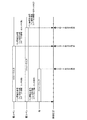
図12は、図1に示した電子ペンシステムにおける手書き入力の一例を示す図である。図13は、図12に示した手書き入力時のペン情報の送信状況を示すタイミング図である。手書きで一連の文字を入力する場合、短い間隔をおいてストローク入力S1〜S11が繰り返されるが、各ストローク入力S1〜S11の始点でタッチ状態になる度に電子ペン1がペン情報の無線通信を行うと電池29の消耗が早くなる。
FIG. 12 is a diagram illustrating an example of handwriting input in the electronic pen system illustrated in FIG. 1. FIG. 13 is a timing chart showing a transmission state of pen information at the time of handwriting input shown in FIG. When inputting a series of characters by handwriting, the stroke inputs S1 to S11 are repeated at short intervals, but each time the
そこで、電子ペン1は、1つのストローク入力が終了してペン先部23がタッチ面2から離れて、磁気センサー26による検出結果がタッチ状態から非タッチ状態となった後に、その非タッチ状態が所定時間(T:例えば2sec)継続する前に、再度タッチ状態となった場合には、ペン情報を送信しない。これにより、電子ペン1の通信回数を削減することができ、電池29の消耗を抑制することができる。
Therefore, after the end of one stroke input and the
同じ指示物(電子ペン1や指F)で1つの文字列を入力する際には、ストローク入力は短い間隔となるが、異なる指示物で別々に文字列を入力する際には、1つの指示物で入力される文字列の最後のストローク入力と、別の指示物で入力される文字列の最初のストローク入力とは長い間隔となり、基準時間(T:例えば2sec)を適切に定めることで、1つの指示物で文字列を入力する最中にはペン情報が送信されず、1つの指示物で文字列が入力された後に、別の指示物で文字列の入力が開始したところでペン情報が送信されるようにすることができる。
When inputting a single character string with the same indicator (
図示する例では、「あい」の文字列と「かき」の文字列とは異なる指示物で別々に入力され、「あい」並びに「かき」の各文字列の入力における最初のストローク入力の始点のタイミング(即ち図13では、S1及びS6の先頭のタイミング)でのみペン情報が送信される。 In the example shown in the figure, the character string “Ai” and the character string “Kaki” are input separately with different indicators, and the starting point of the first stroke input in the input of each character string “Ai” and “Kaki” The pen information is transmitted only at the timing (that is, the leading timings of S1 and S6 in FIG. 13).
この場合、制御装置6は、2番目以降のストローク入力では電子ペン1からのペン情報を受信しない。このため、ペン情報の有無で、各ストローク入力が電子ペン1と指Fとのいずれによるかを判別することができない。またペン情報中のペン識別情報で、各ストローク入力がいずれの電子ペン1によるかを判別することができない。
In this case, the
そこで、制御装置6は、ストローク入力の終点を検出した後に、新たなストローク入力の始点を検出すると、その2つのストローク入力が所定の近接条件(例えば±50mmの範囲)を満足する場合に、新たなストローク入力をその近接するストローク入力と同じ指示物によるものと判断する。
Therefore, when the
ここで、近接条件は、ストローク入力の終点を検出してから新たなストローク入力の始点を検出するまでの経過時間、及びストローク入力の終点と新たなストローク入力の始点との離間距離のいずれか一方あるいは双方について設定される。この近接条件を満足する場合には、1つの指示物で文字列を連続して入力しているものと判断することができ、一方、近接条件を満足しない場合には、指示物を変えて別の文字列を入力している可能性があるものと判断することができる。 Here, the proximity condition is any one of the elapsed time from the detection of the stroke input end point to the detection of the new stroke input start point, and the separation distance between the stroke input end point and the new stroke input start point. Or it sets about both. When this proximity condition is satisfied, it can be determined that the character string is continuously input with one indicator. On the other hand, when the proximity condition is not satisfied, the indicator is changed. It can be determined that there is a possibility that the character string is input.
これにより、タッチ状態となる度にペン情報を送信せずとも、各ストローク入力の指示物を精度良く判別することができる。 Accordingly, it is possible to accurately determine the instruction for each stroke input without transmitting pen information every time the touch state is entered.
また、所定の近接条件を満足する以前のストローク入力が存在しない場合には、ユーザに指示物を指定させる確認画面を表示装置5によりタッチ面2上に表示させる。又は電子ペン1に属性情報を再送信させるため、ユーザに電子ペン1を所定期間(例えば2sec)以上、タッチ面2から離間させるよう促す表示を行なう。又は電子ペン1に強制的に属性情報を送信するための指示手段(例えばプッシュスイッチ)を設けてもよい。これにより、ストローク入力の指示物を特定してその指示物の属性に基づいた適切な文字を入力することができる。
If there is no previous stroke input that satisfies the predetermined proximity condition, a confirmation screen for allowing the user to specify an instruction is displayed on the
なお、このように所定の近接条件にしたがって指示物を特定すると共に、指示物を特定することができない場合にユーザに指示物を指定させる確認画面を表示させる等の動作は、前記のように手書きで文字を入力する場合に限定されない。文字以外の入力時に指示物を特定することができない場合にも同様に適用することができる。 The operation of specifying the indicator according to the predetermined proximity condition and displaying the confirmation screen for allowing the user to specify the indicator when the indicator cannot be specified is performed by handwriting as described above. It is not limited to inputting characters with. The present invention can also be applied in the same manner when an indicator cannot be specified when inputting characters other than characters.
図14は、図1に示した電子ペンシステムにおける手書き入力時のペン情報の送信状況を示すタイミング図である。電子ペン1は、1つのストローク入力が終了してペン先部23がタッチ面2から離れて、磁気センサー26による検出結果がタッチ状態から非タッチ状態となるのに応じて、ペン識別情報、及びステータス情報(非タッチ状態)を含むペン情報を制御装置6に送信する。
FIG. 14 is a timing diagram showing a transmission state of pen information during handwriting input in the electronic pen system shown in FIG. When the
一方、制御装置6は、ストローク入力の最中は、位置検出装置4から徐々に変化する位置検出情報を受信するが、1つのストローク入力が終了して電子ペン1のペン先部23や指Fがタッチ面から離れると、一連の位置検出情報が消失するストローク入力の終点を検出するが、このストローク入力の終点の検出が、電子ペン1からの非タッチ状態を示すペン情報を受信するのと略同じタイミングとなった場合には、そのストローク入力を電子ペン1によるものと判断する。また、ストローク入力の終点を検出したところでペン情報を受信しなかった場合には、そのストローク入力を指Fによるものと判断する。
On the other hand, during the stroke input, the
電子ペン1と指Fとでストローク入力の始点のタイミングが同時の場合、ストローク入力の始点のタイミングで電子ペン1から制御装置6に送信されるペン情報のみでは各ストローク入力が電子ペン1と指Fとのいずれによるかを判別することができないが、ストローク入力の終点でもペン情報を送信するようにすると、各ストローク入力が電子ペン1と指Fとのいずれによるかを判別することができる。
When the timing of the stroke input start point is the same for the
また、複数の電子ペン1でストローク入力の始点のタイミングが重なると、同様にストローク入力の始点のタイミングで電子ペン1から制御装置6に送信されるペン情報のみでは各ストローク入力がいずれの電子ペン1によるかを判別することができないが、ストローク入力の終点でもペン情報を送信するようにすると、各ストローク入力がいずれの電子ペン1によるかを判別することができる。
In addition, when the timing of the stroke input start point overlaps with the plurality of
また、ストローク入力の始点及び終点のタイミングが共に重なると、ストローク入力の始点及び終点のタイミングで電子ペン1から制御装置6に送信されるペン情報でストローク入力の指示物を特定することができないが、このような事態も皆無ではない。そこで、このような場合に、複数回のストローク入力が連続して行われている場合では、位置的に近接し且つ時間的にも近接するストローク入力の指示物情報から類推判別するようにするとよい。一方、単発的なストローク入力の場合には、ストローク入力が行われた位置の近傍のタッチ面上に、電子ペン1と指Fのいずれであるかをユーザに確認する確認ウィンドウを表示し、ユーザに選択させてストローク入力の指示物を特定するようにするとよい。
Further, if the timings of the start point and the end point of the stroke input overlap, the stroke input instruction cannot be specified by the pen information transmitted from the
図15は、図1に示した複数の電子ペン1と制御装置6との動作を簡略化して示すタイミング図である。ここでは、複数の電子ペン1を同時にタッチ操作した例を示している。
FIG. 15 is a timing chart showing simplified operations of the plurality of
電子ペン1は、ペン先部23をタッチ面2に押し付けてタッチ状態が検出されると、通信要求信号(REQ(1),REQ(2),…REQ(n))を制御装置6に送信する。制御装置6は、電子ペン1からの通信要求信号(REQ)の受信に応じて、応答信号(ACK(1),ACK(2),…ACK(n))を各電子ペン1に送信する。電子ペン1は、制御装置6からの応答信号(ACK)の受信に応じて、ペン情報(DATA)を制御装置6に送信する。
The
このとき、電子ペン1は、ペン情報(DATA)の送信を開始してから、一定の遅延時間(t1)の後、ペン先部23と把持部21との電気的接続を断続する接続スイッチ25をオンとする。これにより各電子ペン1では、位置検出可能な状態となり、各電子ペン1のタッチ位置(位置1、位置2、位置3)が順次検出される。
At this time, the
なお、ここでは、通信の衝突回避のために、無線LANなどで公知の分散制御型のコンテンション(CSMA→T1→独立待ち時間(乱数)→データ転送→ACK)を利用している。例えば、各電子ペン1からは、無線チャネルが使用されていないことを確認するCSMA(Carrier Sense Multiple Access)を行う。もし、複数の電子ペンからの同時の通信要求による衝突が発生した場合は、図15に示すように、待機単位時間と発生させた乱数で決定される各電子ペン1で異なる独立待ち時間(tw1、tw2、twn)を待機した後に各電子ペン1は再度通信要求を送信して衝突回避し、制御装置6からの応答信号ACKに応じてデータ転送を行い、制御装置6が電子ペン1からの要求に対応して、毎回、データ受信を確認する応答信号ACKを返すという一連の通信動作を行っている。さらに、図示していないが、電子ペン1がデータ転送後に制御装置6からの応答信号ACKを受信できなかった場合は、応答信号ACKを受信するまで、データの再転送を繰り返すことで、確実なデータ転送を行っている。
Here, in order to avoid communication collision, a known distributed control type contention (CSMA → T1 → independent waiting time (random number) → data transfer → ACK) is used in a wireless LAN or the like. For example, each
このようにすれば、複数の電子ペン1の個々の属性情報を、制御装置6に確実に伝送することができるから、例えば四人のユーザがそれぞれ異なる電子ペン1を用いて、それぞれが使用する描画色を任意に(即ち独立して)選択することが可能となる。つまり各電子ペン1の描画色をユーザ毎に黒、赤、青、緑のように異ならせることも、全てのユーザが同一の描画色を選択することも可能となる。もちろん電子ペン1の属性情報は描画色に限るものではなく、例えば実線/破線、線の太さに関する属性情報であってもよい。このように本実施形態の電子ペン1は、同時に複数の電子ペン1が使用される場合であっても、その属性情報を個別独立して設定可能であり、他の電子ペン1による制約を一切受けない。
In this way, since the individual attribute information of the plurality of
ところで、前記のように、タッチ操作を行った指示物が電子ペン1と指Fとのいずれであるかを間違いなく判別することができるため、電子ペン1と指Fとに異なる機能を与えることで、様々な操作が可能になる。ここでは、電子ペン1及び指Fのタッチ操作で表示オブジェクトの編集(移動、回転、拡大及び縮小)を行う例について説明する。
By the way, as described above, since it is possible to definitely determine which of the
図16は、図1に示した制御装置6の描画制御部17の概略構成を示す模式図である。制御装置6の描画制御部17は、前記のようにタッチ操作を行った指示物が電子ペン1と指Fとのいずれであるかを判別する指示物判別部(指示物判別手段)171と、電子ペン1によるタッチ操作に応じて所定のペン入力処理を行なう第1の制御部(第1の制御手段)172と、指Fのタッチ操作に応じて所定の指入力処理を行なう第2の制御部(第2の制御手段)173と、を備え、第1の制御部172のペン入力処理と第2の制御部173の指入力処理とを並行して実行させるようになっている。これにより、電子ペン1と指Fを機能分担させ、電子ペン1及び指Fの各々に予め設定された機能にしたがった処理を同時に並行して実行することができる。
FIG. 16 is a schematic diagram illustrating a schematic configuration of the
既に説明したように、制御装置6は、パソコン及び周辺機器で構成され、描画制御部17の機能はアプリケーションプログラムを実行することで提供される。従ってここで「並行して実行」とは、OSのいわゆるマルチタスク処理による並列処理を意味する。
As already described, the
第1の制御部172は、電子ペン1によるタッチ操作及び当該電子ペン1に設定された属性に応じた描画処理を行なう。第2の制御部173は、表示オブジェクトに対して指Fのタッチ操作に応じた編集処理を行なう。なお、第1・第2の制御部172・173に、これとは異なる機能を与えることも可能である。
The
また、制御装置6の描画制御部17は、ユーザの指示に応じて、指Fによるタッチ操作を電子ペン1によるものとみなす指描画モードを有し、この指描画モードでは、標準的な属性で指Fによるタッチ操作に応じた描画処理を第1の制御部172に行わせるようにしている。これにより、電子ペン1の代用として指Fによるタッチ操作で描画を行うことができる。
Further, the
ここで、指描画モードでは、指Fによるタッチ操作に応じた描画処理を標準的な属性で行うが、この標準的な属性として、例えば描画色に関しては黒とする。なお、指描画モードでは、第2の制御部173は動作を停止した状態となる。
Here, in the finger drawing mode, drawing processing corresponding to the touch operation with the finger F is performed with a standard attribute. As this standard attribute, for example, the drawing color is black. In the finger drawing mode, the
図17・図18は、複数の指示物(電子ペン1や指F)を同時にタッチして表示オブジェクトを編集する共同操作の状況を示す模式図である。制御装置6の描画制御部17は、複数の指示物で表示オブジェクト上をタッチして表示オブジェクトを編集する際に、最初に表示オブジェクト上をタッチした第1の指示物のタッチ位置を操作起点とし、次に表示オブジェクト上をタッチした第2の指示物のタッチ位置を操作作用点として、第1の指示物の移動に伴う操作起点の絶対的な変位量と、第2の指示物の移動に伴う操作起点に対する操作作用点の相対的な変位量に応じて、表示オブジェクトの描画情報を生成して画面表示させる。
FIG. 17 and FIG. 18 are schematic diagrams illustrating a situation of joint operation in which a plurality of instructions (
ここで、操作起点を設定する第1の指示物は電子ペン1とし、操作作用点を設定する第2の指示物は指Fとする。なお、第2の指示物は別の電子ペン1とすることも可能である。
Here, the first indicator for setting the operation starting point is the
図17に示す例は、回転モードで、操作起点を設定する電子ペン1の動きに応じて表示オブジェクトが平行移動され、操作作用点を設定する指Fの動きに応じて表示オブジェクトが回転されている。ここで、表示オブジェクトの回転は、操作起点、すなわち電子ペン1によるタッチ位置を中心点として行われる。
In the example shown in FIG. 17, in the rotation mode, the display object is translated according to the movement of the
図18に示す例は、拡大・縮小モードで、操作起点を設定する電子ペン1の動きに応じて表示オブジェクトが平行移動され、操作作用点を設定する指Fの動きに応じて表示オブジェクトが拡大・縮小されている。ここで、電子ペン1と指Fとの相対的な距離が大きくなれば拡大となり、電子ペン1と指Fとの相対的な距離が小さくなれば縮小となる。
In the example shown in FIG. 18, in the enlargement / reduction mode, the display object is translated according to the movement of the
また、前記と同様に操作起点及び操作作用点を設定して、第2の指示物の移動に伴う操作起点に対する操作作用点の相対的な変位量に応じて、表示オブジェクトの描画情報を連続的に生成して画面表示させ、第2の指示物をタッチ面から離すと、表示オブジェクトの描画情報の生成を終了させるものとしてもよい。これにより、第2の指示物の動きに応じて表示オブジェクトの編集状況が逐次画面表示されるため、ユーザは表示オブジェクトの編集状況を見ながら操作を行うことができる。 In addition, the operation starting point and the operation action point are set in the same manner as described above, and the drawing information of the display object is continuously displayed according to the relative displacement amount of the operation action point with respect to the operation starting point accompanying the movement of the second indicator. When the second indicator is separated from the touch surface, the generation of the display object drawing information may be terminated. Accordingly, the editing status of the display object is sequentially displayed on the screen in accordance with the movement of the second indicator, so that the user can perform an operation while viewing the editing status of the display object.
図19は、図16に示した制御装置6での処理手順を示すフロー図である。ここでは、タッチ操作を行った指示物が電子ペン1及び指Fのいずれであるか、さらに手書きモードか否かに応じて、指操作(ST503)、指手書き動作(ST504)、ペン操作(ST509)、ペン手書き動作(ST510)の4つに分かれる。指手書き動作は、入力検出位置に、指用に予め設定された手書き属性(色・太さ・線種)に基づいて描画する。ペン手書き動作は、入力検出位置に、複数の電子ペン1ごとに予め設定された手書き属性(色・太さ・線種)に基づいて描画する。
FIG. 19 is a flowchart showing a processing procedure in the
指操作(ST503)、及びペン操作(ST509)において、電子ペン1と指Fが同一の表示オブジェクトに触れている場合には、共同操作(ST507、ST513)に進む。一方、電子ペン1と指Fが同一の表示オブジェクトに触れていない場合には、独立操作(ST506、ST512)に進む。
In the finger operation (ST503) and the pen operation (ST509), when the
独立操作では、ペン入力及び指入力に応じてメニュー選択された動作モードに従って、表示オブジェクトを操作する。例えば、表示オブジェクトに対する回転、移動、拡大及び縮小の処理、表示オブジェクトの色の変更、表示オブジェクトの選択、メニュー表示など、アプリケーションの制御に関する操作が対象となる。 In the independent operation, the display object is operated according to the operation mode selected from the menu according to the pen input and the finger input. For example, operations related to application control, such as rotation, movement, enlargement / reduction processing, display object color change, display object selection, menu display, and the like, are targeted.
図20は、図19に示した電子ペン1と指Fの共同操作の処理手順を示すフロー図である。まず、電子ペン1の移動を検出すると(ST601)、表示オブジェクトを平行移動する処理が行われる(ST602)。そして、指Fの移動を検出すると(ST603)、指Fの移動方向及び移動量に応じたベクトル計算を行い(ST604)、電子ペン1のタッチ位置を支点として表示オブジェクトをベクトル値に基づいて回転・拡大・縮小の処理が行われる(ST605)
FIG. 20 is a flowchart showing a processing procedure of the joint operation of the
ところで、前記のように、複数の電子ペン1を異なる属性に設定して使い分けることができるため、複数の電子ペン1で別々に描かれた画像が重なり合う場合に、両画像の重複部分をどのように描画するかが問題となる。
By the way, as described above, since a plurality of
図21・図22は、図1に示した複数の電子ペン1で線を描画する際の状況を示す模式図である。制御装置6の描画制御部(描画制御手段)17は、以前に描画された画像に重なり合うように新たな画像が描画される場合に、両画像の重複部分を予め指定された描画規則に基づいて描画する。電子ペン1は、描画規則をユーザに指定させる操作スイッチ(描画規則指定手段)44を備え、この操作スイッチで指定された描画規則に関する情報を制御装置6に送信する。
FIG. 21 and FIG. 22 are schematic views showing a situation when a line is drawn with the plurality of
なお、描画規則を、表示装置5によりタッチ面2上に表示されるメニューで選択指定するようにしてもよい。
Note that the drawing rule may be selected and specified from a menu displayed on the
図21に示すように、描画規則は、以前に第1の描画条件で描画された画像と新たに第2の描画条件で描画される画像との重複部分を、新たな画像の描画条件である第2の描画条件にしたがって描画する上書き処理に関するものである。図示する例では、描画条件を描画色としている。 As shown in FIG. 21, the drawing rule is a drawing condition for a new image, which is an overlapping portion between an image previously drawn under the first drawing condition and an image newly drawn under the second drawing condition. The present invention relates to an overwriting process for drawing according to the second drawing condition. In the illustrated example, the drawing condition is the drawing color.
上書き処理を行う旨が指定されている場合には、図21(A)に示すように、以前に描画された画像と新たに描画される画像との重複部分が、新たに描画される画像の色に置き換えられる。すなわち、第1の重複部分では、元の青色が黄色に置き換えられ、第2の重複部分では、元の黄色が青色に置き換えられる。一方、上書き処理を行わない旨が指定されている場合には、図21(B)に示すように、以前に描画された画像と新たに描画される画像との重複部分が、元の色のままで残される。 When it is designated that overwriting is to be performed, as shown in FIG. 21A, the overlapping portion between the previously drawn image and the newly drawn image is the same as the newly drawn image. Replaced by color. That is, in the first overlapping portion, the original blue color is replaced with yellow, and in the second overlapping portion, the original yellow color is replaced with blue. On the other hand, when it is designated that the overwriting process is not performed, as shown in FIG. 21B, the overlapping portion between the previously drawn image and the newly drawn image is the original color. Left untouched.
また、図22に示すように、描画規則は、第1の描画条件で以前に描画された画像と第2の描画条件で新たに描画される画像とが重なり合う部分を、両者の描画条件を指定の比率により変更した別の描画条件で描画する重ね合わせ処理に関するものである。図示する例では、描画条件を描画色としている。指定の比率による変更について、以下、平均化処理を行なう例を説明する。 In addition, as shown in FIG. 22, the drawing rule specifies a drawing condition for a portion where an image previously drawn under the first drawing condition and an image newly drawn under the second drawing condition overlap. The present invention relates to a superimposition process for drawing under another drawing condition changed according to the ratio of the above. In the illustrated example, the drawing condition is the drawing color. An example of performing an averaging process for the change by the specified ratio will be described below.
重ね合わせ処理を行う旨が指定されている場合には、図22(A)に示すように、以前に描画された画像と新たに描画される画像との重複部分が、両者の描画色を平均化した混合色に置き換えられる。一方、重ね合わせ処理を行わない旨が指定されている場合には、図22(B)に示すように、新たに描画される画像の色に置き換えられる。これは図21(A)の上書き処理と同じである。 When it is designated that superimposition processing is to be performed, as shown in FIG. 22A, the overlapping portion between the previously drawn image and the newly drawn image averages the drawing colors of both. It is replaced with the mixed color. On the other hand, when it is specified that the superimposition process is not performed, as shown in FIG. 22B, the color of the newly drawn image is replaced. This is the same as the overwriting process in FIG.
さらにここでは、後から描かれた画像が強調されるように色の混合比率を設定してもよい。すなわち、以前に描画された画像の第1の描画色と、新たに描画される画像の第2の描画色に対して、重み付け係数による加重平均を行って混合色を算出する。 Further, the color mixing ratio may be set so that an image drawn later is emphasized. That is, a mixed color is calculated by performing a weighted average with a weighting coefficient on the first drawing color of the previously drawn image and the second drawing color of the newly drawn image.
第1の重複部分では、先に青色の電子ペン1で描かれた青色の線と、後から黄色の電子ペン1で描かれた黄色の線とが重なり合い、後から描かれた黄色が強調されるように、両方の色の混合比率(黄色:青色)を6:4とした黄緑色に置き換えられる。また、第2の重複部分では、先に黄色の電子ペン1で描かれた黄色の線と、後から青色の電子ペン1で描かれた青色の線とが重なり合い、後から描かれた青色が強調されるように、両方の色の混合比率(青色:黄色)を6:4とした青緑色に置き換えられる。
In the first overlapping portion, the blue line drawn with the blue
これにより、描画色の異なる別の電子ペン1で2つの線が描かれたことをユーザが容易に認識することができる。さらに、重複部分の色を時間的な先後関係に応じて変更することで、互いに交差する2本の線のいずれが後から描画されたかをユーザが容易に認識することができる。
Accordingly, the user can easily recognize that two lines are drawn with another
なお、2色の混合比を、線の太さの割合に比例して設定するようにしてもよい。また、2つの線が交差して混合色に変化した部分にさらに別の線が交差する場合には、その交差部分を、元の混合色と新たな色とを混合した混合色に変更し、このような色変更を、線が交差する度に行うようにしてもよい。さらに、電子ペン1をイレーサーモードとした場合は、通常、後から描かれた領域が消去されるが、種々の消去モードを指定することができるようにする、例えば消去率を選択することで、後から描かれた領域の濃度を薄くすることや、消去模様を選択することで、消去模様によって部分的に消去させることもできる。
The mixing ratio of the two colors may be set in proportion to the ratio of the line thickness. In addition, when another line intersects the part where the two lines intersect and change to the mixed color, the intersected part is changed to a mixed color obtained by mixing the original mixed color and the new color, Such a color change may be performed every time the lines intersect. Furthermore, when the
また、表示オブジェクトの画像編集を行う際に、複数の電子ペン1で1つの表示オブジェクトを同時にタッチした場合に、特殊な機能を割り当てるようにしてもよい。例えば、制御装置6が、複数の電子ペン1による同時タッチを検知すると、表示オブジェクトの画像処理(ハイライト、強調、色変換など)を行うようにする。また、制御装置6が、複数の電子ペン1による同時タッチを検知すると、それらの電子ペン1の属性(例えば描画色)をランダムに変更するようにする。これにより、表示オブジェクトにユーザが予期しない変化(インタラクション)が起こり、ブレーンストーミングやデザインの検討でアイデアのヒントやトリガになる効果が得られる。
In addition, when performing image editing of a display object, a special function may be assigned when a plurality of
本発明にかかる電子ペンシステムは、複数の電子ペンの各々をユーザが必要に応じて属性を切り替えて使用することができる効果を有し、複数の電子ペンを使い分けて同時に使用することができるようにした電子ペンシステムなどとして有用である。 The electronic pen system according to the present invention has an effect that the user can use each of the plurality of electronic pens by switching the attributes as needed, so that the plurality of electronic pens can be used separately and used simultaneously. It is useful as an electronic pen system.
1 電子ペン
2 タッチ面
3 タッチパネル体
4 位置検出装置
5 表示装置
6 制御装置
16 無線通信部
17 描画制御部(描画制御手段)
18 表示制御部
19 主制御部
44 操作スイッチ(属性選択手段、描画規則指定手段)
DESCRIPTION OF
18
Claims (5)
前記電子ペンは、属性をユーザにより選択させる属性選択手段と、この属性選択手段により選択された属性情報及び自身の識別情報を付加したペン情報を前記制御装置に送信するペン情報送信手段と、前記タッチ面に対するタッチ状態を検出するタッチ状態検出手段と、を備え、前記タッチ状態検出手段がタッチ状態を検出するのに応じて前記ペン情報送信手段から前記制御装置に前記ペン情報を送信した後に、前記電子ペンのペン先部を導通させて前記位置検出装置によるタッチ位置の検出を可能とし、
前記制御装置は、前記電子ペンから前記ペン情報を受信した後、一定時間内に前記位置検出装置からタッチ位置を受信した場合には、前記ペン情報に付加された識別情報を有する電子ペンによるタッチ操作と判断し、当該ペン情報に含まれる属性情報に応じた画像を前記表示装置に表示させることを特徴とする電子ペンシステム。 A touch panel body including a plurality of electronic pens, a touch surface on which a touch operation is performed by the electronic pen, a position detection device that detects a touch position of the electronic pen on the touch surface, and a display screen for the touch surface As an electronic pen system comprising: a display device that displays a required image as a control device that causes the display device to display an image according to position detection information acquired from the position detection device;
The electronic pen includes attribute selection means for selecting an attribute by a user, pen information transmission means for transmitting pen information to which the attribute information selected by the attribute selection means and its identification information are added to the control device, Touch state detection means for detecting a touch state on the touch surface, and after the pen information transmission means transmits the pen information to the control device in response to the touch state detection means detecting the touch state, Enabling the detection of the touch position by the position detection device by conducting the pen tip portion of the electronic pen,
When the control device receives a touch position from the position detection device within a predetermined time after receiving the pen information from the electronic pen, the control device touches with the electronic pen having identification information added to the pen information. An electronic pen system characterized in that an operation is determined and an image corresponding to attribute information included in the pen information is displayed on the display device.
前記電子ペンは、前記描画規則をユーザに指定させる描画規則指定手段を備え、この描画規則指定手段で指定された描画規則に関する情報を前記制御装置に送信することを特徴とする請求項1に記載の電子ペンシステム。 When a new image is drawn so as to overlap with a previously drawn image, the control device uses a drawing rule designated in advance as an overlapping portion between the previously drawn image and the newly drawn image. A drawing control means for drawing based on
The electronic pen, the drawing rule includes a writing rule specifying means for specifying a user, wherein the information related to the drawing rules specified in this drawing rule specifying means to claim 1, characterized by transmitting to the control unit Electronic pen system.
前記電子ペンの属性をユーザにより選択させる属性選択手段と、この属性選択手段により選択された属性及び自身の識別情報を付加したペン情報を前記制御装置に送信するペン情報送信手段と、前記タッチ面に対するタッチ状態を検出するタッチ状態検出手段と、を備え、前記タッチ状態検出手段がタッチ状態を検出するのに応じて前記ペン情報送信手段から前記制御装置に前記ペン情報を送信した後に、前記電子ペンのペン先部を導通させてタッチ位置の検出を可能とすることを特徴とする電子ペン。 Communicating with a control device for displaying on the display screen an image according to a touch position of the electronic pen on the touch surface and an attribute of the electronic pen, with a touch surface on which touch operations are performed by a plurality of electronic pens being performed An electronic pen that performs
Attribute selecting means for selecting an attribute of the electronic pen by a user, pen information transmitting means for transmitting pen information to which the attribute selected by the attribute selecting means and its identification information are added to the control device, and the touch surface Touch state detecting means for detecting a touch state with respect to the electronic device, the pen information transmitting means transmitting the pen information to the control device in response to the touch state detecting means detecting the touch state, An electronic pen characterized in that a pen tip portion of a pen is conducted to detect a touch position .
Priority Applications (2)
| Application Number | Priority Date | Filing Date | Title |
|---|---|---|---|
| JP2010004125A JP4913873B2 (en) | 2010-01-12 | 2010-01-12 | Electronic pen system and electronic pen |
| US12/987,334 US8482539B2 (en) | 2010-01-12 | 2011-01-10 | Electronic pen system |
Applications Claiming Priority (1)
| Application Number | Priority Date | Filing Date | Title |
|---|---|---|---|
| JP2010004125A JP4913873B2 (en) | 2010-01-12 | 2010-01-12 | Electronic pen system and electronic pen |
Publications (3)
| Publication Number | Publication Date |
|---|---|
| JP2011145763A JP2011145763A (en) | 2011-07-28 |
| JP2011145763A5 JP2011145763A5 (en) | 2011-10-06 |
| JP4913873B2 true JP4913873B2 (en) | 2012-04-11 |
Family
ID=44460585
Family Applications (1)
| Application Number | Title | Priority Date | Filing Date |
|---|---|---|---|
| JP2010004125A Active JP4913873B2 (en) | 2010-01-12 | 2010-01-12 | Electronic pen system and electronic pen |
Country Status (1)
| Country | Link |
|---|---|
| JP (1) | JP4913873B2 (en) |
Families Citing this family (19)
| Publication number | Priority date | Publication date | Assignee | Title |
|---|---|---|---|---|
| JP5462044B2 (en) * | 2010-03-23 | 2014-04-02 | 株式会社アサヒ | Case for electronic equipment |
| JP6106983B2 (en) | 2011-11-30 | 2017-04-05 | 株式会社リコー | Image display device, image display system, method and program |
| JP5454722B2 (en) * | 2011-11-30 | 2014-03-26 | 株式会社リコー | Projector, display device, method and program |
| JP5152771B1 (en) * | 2012-04-02 | 2013-02-27 | 株式会社シェリー | Touch pen for capacitive touch panel |
| US8803850B2 (en) | 2012-06-15 | 2014-08-12 | Blackberry Limited | Stylus with control ring user interface |
| EP2674837A1 (en) * | 2012-06-15 | 2013-12-18 | BlackBerry Limited | Stylus with control ring user interface |
| JP6160057B2 (en) * | 2012-10-04 | 2017-07-12 | 大日本印刷株式会社 | Medical entry system transcription system and program |
| JP2016509275A (en) * | 2012-11-29 | 2016-03-24 | ルノー エス.ア.エス. | Communication system and method for reproducing physical type interactivity |
| JP6087602B2 (en) * | 2012-12-03 | 2017-03-01 | シャープ株式会社 | Electronic blackboard |
| KR101984592B1 (en) * | 2013-01-04 | 2019-05-31 | 엘지전자 주식회사 | Mobile terminal and method for controlling the same |
| JP6286836B2 (en) * | 2013-03-04 | 2018-03-07 | 株式会社リコー | Projection system, projection apparatus, projection method, and projection program |
| JP2014219841A (en) * | 2013-05-08 | 2014-11-20 | 住友電工ネットワークス株式会社 | Operation input device and operation input program |
| JP2015022410A (en) * | 2013-07-17 | 2015-02-02 | シャープ株式会社 | Multi-mode input system and information processing system |
| JP6094550B2 (en) * | 2013-09-17 | 2017-03-15 | 株式会社リコー | Information processing apparatus and program |
| JP6335024B2 (en) * | 2014-05-28 | 2018-05-30 | シャープ株式会社 | Display device, display method, display program, and electronic blackboard |
| JP6450026B2 (en) * | 2015-04-21 | 2019-01-09 | ヘン、クェイ ヒンHEUNG, Kwei Hing | Improved input device |
| KR102523154B1 (en) * | 2016-04-22 | 2023-04-21 | 삼성전자주식회사 | Display apparatus, input device and control method thereof |
| JP2020144413A (en) | 2019-03-04 | 2020-09-10 | セイコーエプソン株式会社 | Display method and display apparatus |
| JP7329938B2 (en) * | 2019-03-19 | 2023-08-21 | 株式会社ワコム | Information processing system, position indicator, and method for controlling movement of displayed object displayed on display screen of information processing device |
Family Cites Families (8)
| Publication number | Priority date | Publication date | Assignee | Title |
|---|---|---|---|---|
| JPS608926A (en) * | 1983-06-28 | 1985-01-17 | Pentel Kk | Pen touch type information input device |
| DE68928987T2 (en) * | 1989-10-02 | 1999-11-11 | Koninkl Philips Electronics Nv | Data processing system with a touch display and a digitizing tablet, both integrated in an input device |
| JP2599019B2 (en) * | 1990-06-28 | 1997-04-09 | 三洋電機株式会社 | Pen input device |
| JPH07160398A (en) * | 1993-12-08 | 1995-06-23 | Canon Inc | Pen input device |
| JPH07200131A (en) * | 1993-12-28 | 1995-08-04 | Casio Comput Co Ltd | Pen input system |
| JPH07225644A (en) * | 1994-02-10 | 1995-08-22 | Wacom Co Ltd | Position indicator |
| JP3837812B2 (en) * | 1997-01-30 | 2006-10-25 | 株式会社ワコム | Cordless electronic pen with cartridge |
| JP2000172421A (en) * | 1998-12-04 | 2000-06-23 | Hitachi Software Eng Co Ltd | Electromagnetic induction electronic board |
-
2010
- 2010-01-12 JP JP2010004125A patent/JP4913873B2/en active Active
Also Published As
| Publication number | Publication date |
|---|---|
| JP2011145763A (en) | 2011-07-28 |
Similar Documents
| Publication | Publication Date | Title |
|---|---|---|
| JP4913873B2 (en) | Electronic pen system and electronic pen | |
| JP4857385B2 (en) | Electronic pen system | |
| JP4886863B2 (en) | Electronic pen system and electronic pen | |
| US8482539B2 (en) | Electronic pen system | |
| CN103353828B (en) | The method and device of function is write and is wiped in a kind of switching on the touchscreen | |
| JP5507494B2 (en) | Portable electronic device with touch screen and control method | |
| KR101383840B1 (en) | Remote controller, system and method for controlling by using the remote controller | |
| JP2004054589A (en) | Information display input device and method, and information processor | |
| WO2012132802A1 (en) | Touch panel device, display method therefor, and display program | |
| JP2013186869A (en) | Touch panel system, stylus and plotting function setting method | |
| WO2011142151A1 (en) | Portable information terminal and method for controlling same | |
| JP5374564B2 (en) | Drawing apparatus, drawing control method, and drawing control program | |
| JP2014229017A (en) | Electronic apparatus, position designation method and program | |
| US20150138082A1 (en) | Image display apparatus and image display system | |
| CN202110523U (en) | Terminal equipment and icon position interchanging device of terminal equipment | |
| CN108595076A (en) | A kind of electronic equipment touch-control exchange method | |
| CN108459790A (en) | A kind of electronic equipment touch-control exchange method | |
| CN202133989U (en) | Terminal unit and icon position exchanging device thereof | |
| JP6015183B2 (en) | Information processing apparatus and program | |
| CN108595075A (en) | A kind of electronic equipment touch-control exchange method | |
| US11216121B2 (en) | Smart touch pad device | |
| KR100984826B1 (en) | Portable terminal and user interface method thereof | |
| JP6411067B2 (en) | Information processing apparatus and input method | |
| WO2015174316A1 (en) | Terminal, and terminal control method | |
| CN108563379A (en) | A kind of electronic equipment touch-control exchange method |
Legal Events
| Date | Code | Title | Description |
|---|---|---|---|
| RD02 | Notification of acceptance of power of attorney |
Free format text: JAPANESE INTERMEDIATE CODE: A7422 Effective date: 20110822 |
|
| A521 | Request for written amendment filed |
Free format text: JAPANESE INTERMEDIATE CODE: A523 Effective date: 20110824 |
|
| A621 | Written request for application examination |
Free format text: JAPANESE INTERMEDIATE CODE: A621 Effective date: 20110824 |
|
| A871 | Explanation of circumstances concerning accelerated examination |
Free format text: JAPANESE INTERMEDIATE CODE: A871 Effective date: 20110824 |
|
| A975 | Report on accelerated examination |
Free format text: JAPANESE INTERMEDIATE CODE: A971005 Effective date: 20110906 |
|
| A131 | Notification of reasons for refusal |
Free format text: JAPANESE INTERMEDIATE CODE: A131 Effective date: 20111011 |
|
| A521 | Request for written amendment filed |
Free format text: JAPANESE INTERMEDIATE CODE: A523 Effective date: 20111202 |
|
| TRDD | Decision of grant or rejection written | ||
| A01 | Written decision to grant a patent or to grant a registration (utility model) |
Free format text: JAPANESE INTERMEDIATE CODE: A01 Effective date: 20120110 |
|
| A01 | Written decision to grant a patent or to grant a registration (utility model) |
Free format text: JAPANESE INTERMEDIATE CODE: A01 |
|
| A61 | First payment of annual fees (during grant procedure) |
Free format text: JAPANESE INTERMEDIATE CODE: A61 Effective date: 20120119 |
|
| R150 | Certificate of patent or registration of utility model |
Ref document number: 4913873 Country of ref document: JP Free format text: JAPANESE INTERMEDIATE CODE: R150 Free format text: JAPANESE INTERMEDIATE CODE: R150 |
|
| FPAY | Renewal fee payment (event date is renewal date of database) |
Free format text: PAYMENT UNTIL: 20150127 Year of fee payment: 3 |