JP4913746B2 - Method and apparatus for burning hydrogen in a premix burner - Google Patents
Method and apparatus for burning hydrogen in a premix burner Download PDFInfo
- Publication number
- JP4913746B2 JP4913746B2 JP2007541942A JP2007541942A JP4913746B2 JP 4913746 B2 JP4913746 B2 JP 4913746B2 JP 2007541942 A JP2007541942 A JP 2007541942A JP 2007541942 A JP2007541942 A JP 2007541942A JP 4913746 B2 JP4913746 B2 JP 4913746B2
- Authority
- JP
- Japan
- Prior art keywords
- fuel
- flow
- hydrogen
- burner
- vortex
- Prior art date
- Legal status (The legal status is an assumption and is not a legal conclusion. Google has not performed a legal analysis and makes no representation as to the accuracy of the status listed.)
- Expired - Fee Related
Links
Images


Classifications
-
- F—MECHANICAL ENGINEERING; LIGHTING; HEATING; WEAPONS; BLASTING
- F23—COMBUSTION APPARATUS; COMBUSTION PROCESSES
- F23D—BURNERS
- F23D14/00—Burners for combustion of a gas, e.g. of a gas stored under pressure as a liquid
- F23D14/02—Premix gas burners, i.e. in which gaseous fuel is mixed with combustion air upstream of the combustion zone
-
- F—MECHANICAL ENGINEERING; LIGHTING; HEATING; WEAPONS; BLASTING
- F23—COMBUSTION APPARATUS; COMBUSTION PROCESSES
- F23C—METHODS OR APPARATUS FOR COMBUSTION USING FLUID FUEL OR SOLID FUEL SUSPENDED IN A CARRIER GAS OR AIR
- F23C13/00—Apparatus in which combustion takes place in the presence of catalytic material
-
- F—MECHANICAL ENGINEERING; LIGHTING; HEATING; WEAPONS; BLASTING
- F23—COMBUSTION APPARATUS; COMBUSTION PROCESSES
- F23C—METHODS OR APPARATUS FOR COMBUSTION USING FLUID FUEL OR SOLID FUEL SUSPENDED IN A CARRIER GAS OR AIR
- F23C7/00—Combustion apparatus characterised by arrangements for air supply
- F23C7/002—Combustion apparatus characterised by arrangements for air supply the air being submitted to a rotary or spinning motion
-
- F—MECHANICAL ENGINEERING; LIGHTING; HEATING; WEAPONS; BLASTING
- F23—COMBUSTION APPARATUS; COMBUSTION PROCESSES
- F23D—BURNERS
- F23D17/00—Burners for combustion conjointly or alternatively of gaseous or liquid or pulverulent fuel
- F23D17/002—Burners for combustion conjointly or alternatively of gaseous or liquid or pulverulent fuel gaseous or liquid fuel
-
- F—MECHANICAL ENGINEERING; LIGHTING; HEATING; WEAPONS; BLASTING
- F23—COMBUSTION APPARATUS; COMBUSTION PROCESSES
- F23C—METHODS OR APPARATUS FOR COMBUSTION USING FLUID FUEL OR SOLID FUEL SUSPENDED IN A CARRIER GAS OR AIR
- F23C2900/00—Special features of, or arrangements for combustion apparatus using fluid fuels or solid fuels suspended in air; Combustion processes therefor
- F23C2900/07002—Premix burners with air inlet slots obtained between offset curved wall surfaces, e.g. double cone burners
-
- F—MECHANICAL ENGINEERING; LIGHTING; HEATING; WEAPONS; BLASTING
- F23—COMBUSTION APPARATUS; COMBUSTION PROCESSES
- F23C—METHODS OR APPARATUS FOR COMBUSTION USING FLUID FUEL OR SOLID FUEL SUSPENDED IN A CARRIER GAS OR AIR
- F23C2900/00—Special features of, or arrangements for combustion apparatus using fluid fuels or solid fuels suspended in air; Combustion processes therefor
- F23C2900/9901—Combustion process using hydrogen, hydrogen peroxide water or brown gas as fuel
Landscapes
- Engineering & Computer Science (AREA)
- Chemical & Material Sciences (AREA)
- Combustion & Propulsion (AREA)
- Mechanical Engineering (AREA)
- General Engineering & Computer Science (AREA)
- Chemical Kinetics & Catalysis (AREA)
- Pre-Mixing And Non-Premixing Gas Burner (AREA)
Description
本発明は、水素を含むか又は水素から成るガス状燃料をバーナーによって燃焼する方法及び装置に関する。このバーナーは、渦流発生器を提供する。液体燃料つまり石油が、円錐状に噴出された液体燃料柱を形成しながらバーナー軸線に沿って中心方向に渦流発生器内に供給可能である。この液体燃料柱は、接線方向に渦流発生器内に流入する燃料空気の回転流によって包囲されて混合される。液体燃料つまり天然ガスを供給する手段が、接線方向の空気流入スロットを通じて渦流発生器内に流入する燃焼空気流中にさらに設けられている。 The present invention relates to a method and an apparatus for burning a gaseous fuel containing or consisting of hydrogen by means of a burner. This burner provides a vortex generator. Liquid fuel, ie petroleum, can be fed into the vortex generator in the central direction along the burner axis while forming a conical jet of liquid fuel. This liquid fuel column is surrounded and mixed by the rotating flow of fuel air flowing into the vortex generator in the tangential direction. Means for supplying liquid fuel or natural gas is further provided in the combustion air stream flowing into the vortex generator through a tangential air inlet slot.
いわゆる京都プロトコルで特に決定された温室効果ガスの放出の低減に関するほぼ世界的な取り組みによって動機付けられて、2010年内に予測される温室効果ガスの放出量を1990年内と同じ水準に低減しなければならない。この計画を実行するためには、特に人為改変に関するCO2の低減に寄与することに多大な努力が要求される。人間によって大気中に放出されるCO2のほぼ3分の1が、エネルギー生成のために還元される必要がある。このエネルギー生成の場合、大抵は化石燃料が、発電所設備内でエネルギー生成のために燃焼される。特に近代的な技術を使用することによって及び政治的な限定条件によって、さらに増大するCO2の放出を阻止する大幅な節約の潜在性が、エネルギー生成分野に見て取れる。 Motivated by a nearly global effort to reduce greenhouse gas emissions specifically determined by the so-called Kyoto Protocol, greenhouse gas emissions expected in 2010 must be reduced to the same level as in 1990. Don't be. In order to implement this plan, a great deal of effort is required to contribute to the reduction of CO 2 , especially with respect to human modification. Nearly one third of the CO 2 released into the atmosphere by humans needs to be reduced for energy production. For this energy generation, fossil fuels are usually burned in the power plant equipment for energy generation. The potential for significant savings in the field of energy generation can be seen, especially by using modern technology and by political limitations, preventing further increasing CO 2 emissions.
火力発電所でのCO2の放出を低減するというそれ自体公知でかつ技術的に実現可能な可能性は、燃料を燃焼室内に注入する前に、燃焼に至る燃料から炭素を取り去ることにある。このことは、例えば酸素による燃料の一部の酸化及び/又は水蒸気による燃料の予備処理のような、対応する燃料の予備処理を前提条件とする。このように予備処理された燃料が、多くの場合に大きな割合のH2及びCOを含み、混合比に応じて一般に天然ガスの発熱量より低い発熱量を有する。このように人工的に製造されたガスは、その発熱量に応じてMbtuガス又はLbtuガスと呼ばれる。例えばヨーロッパ特許第0321809号明細書,ヨーロッパ特許出願公開第0780629号明細書,国際特許第93/17279号明細書及びヨーロッパ特許出願公開第1070915号明細書から読み取れるように、これらのガスは、特に天然ガスのような自然ガスを燃焼するために考案された既存のバーナーでの使用に対して適さない。上述した全ての明細書では、燃料予混合型のバーナーが記されている。これらのバーナーの場合、流れ方向に円錐状に拡張する燃焼空気と混合された燃料とから成る渦流がそれぞれ生成される。この渦流は、バーナーから流出した後に、可能な限りでは均一な空気・燃料混合物に達した後に、増大する渦によって不安定になって、コア内で逆流を伴う環状の渦流に変わる。
A per se known and technically feasible possibility to reduce CO 2 emissions at thermal power plants is to remove carbon from the fuel leading to combustion before it is injected into the combustion chamber. This presupposes a corresponding pretreatment of the fuel, for example a partial oxidation of the fuel with oxygen and / or a pretreatment of the fuel with water vapor. Fuels pretreated in this way often contain a large proportion of H 2 and CO and generally have a calorific value lower than that of natural gas, depending on the mixing ratio. The artificially produced gas is called Mbtu gas or Lbtu gas depending on the calorific value. These gases are in particular natural, as can be read from
燃焼概念及び燃焼出力に応じて、予混合バーナー内に形成されている液体燃料及び/又は気体燃料の渦流液が、可能な限り均一な燃料・空気混合物を生成するために供給される。しかしながら上述したように、有害物質の放出、特にCO2の放出を低減する目的で、人工的に提供した気体燃料を既存の種類の燃料の代わりに又は既存の種類の燃料と組み合わせて使用することが必要である。したがって、特別な構造設計が、従来の予混合バーナーシステムに対して要求される。すなわち、人口ガスが、バーナーシステム内に供給するために天然ガスに匹敵して作動するバーナーに比べて何倍もの燃料体積流を必要とする。その結果、明らかに異なる流れの勢い挙動が発生する。人口ガス中の高い割合の水素,これに関連する低い着火温度及び水素の高い燃焼速度に起因して、この燃料は、非常に反応しやすい。この反応のしやすさは、バックフラッシュの危険を高める。このことを回避するため、発火性の燃料・バーナー内の空気混合物の平均滞在時間を可能な限り短くすることが必要である。 Depending on the combustion concept and combustion output, liquid and / or gaseous fuel swirl liquids formed in the premix burner are supplied to produce as homogeneous a fuel / air mixture as possible. However, as mentioned above, artificially provided gaseous fuels may be used instead of or in combination with existing types of fuels for the purpose of reducing the release of harmful substances, especially CO 2 emissions. is required. Therefore, special structural designs are required for conventional premix burner systems. That is, artificial gas requires many times the volume of fuel flow to supply into the burner system compared to a burner operating comparable to natural gas. The result is a distinctly different flow momentum behavior. Due to the high proportion of hydrogen in the man-made gas, the low ignition temperature associated therewith and the high burning rate of hydrogen, this fuel is very responsive. This ease of reaction increases the risk of backflushing. In order to avoid this, it is necessary to make the average residence time of the air mixture in the ignitable fuel / burner as short as possible.
ヨーロッパ特許第0908671号明細書中には、中カロリー又は低カロリーの気体燃料及び液体燃料を燃焼する方法及びバーナーが記されている。この場合、ヨーロッパ特許出願公開第0780629号明細書による後続接続された混合区間を有するダブルコーンバーナーが使用される。中カロリー又は低カロリーの燃料を渦流発生器の内部に軸線方向に及び/又は同軸に注入する供給管が、このダブルコーンバーナーの渦流室を限定する渦流シェル内に設けられている。このような予混合バーナー配置の概略的な構造が、図2,3中に示されている。図2は、予混合バーナー配置の縦断面を示す。図3は、予混合バーナー配置の横断面を示す。この予混合バーナー配置は、円錐状に拡大する渦流発生器1を提供する。この渦流発生器1は、渦流シェル2によって限定されている。燃料を供給する手段が、渦流発生器1の中心軸線Aの周りに軸線方向にかつ同軸に設けられている。したがって、液体燃料BLが、燃料軸線Aに沿って渦流発生器1の最小内径の場所に位置決めされた注入ノズル3を通じて渦流室内に達する。特に天然ガスの形態の気体燃料BGが、接線方向の空気流入スロット4に沿って燃焼空気と混合される。燃焼空気Lは、接線方向の流れ方向で空気流入スロット4を通じて渦流室内に流入する。さらに、注入装置5が設けられている。この注入装置5は、バーナー軸線Aの周りに同軸に配置されていて、中カロリーの燃料BMをさらに供給するために使用される。渦流発生器1内で生成する燃料・空気混合物が、移行部材6によって渦流の形態で混合管8内に達する。移行部材6は、渦流を安定化する流れ手段7を提供する。発火性の燃料・空気混合物が、混合管8の下流に連結している(図示しなかった)燃焼室内で着火される前に、この生成される燃料・空気混合物は、混合管8内で完全に均一に混合される。図3は、渦流シェル2を通過する注入装置5の領域内の渦流発生器1の横断面を示す。空気流入スロット4が、この横断面図中でより良好に目視可能である。空気Lが、この空気流入スロット4を通じて渦流発生器1の内部に流入する。対応する供給管を経由した気体燃料BGが、空気流入スロット4の場所で燃焼空気Lと混合される。液体燃料を渦流発生器1の内部に流出する注入ノズルが、バーナー軸線Aに対して中心に設けられている。
EP 0908671 describes a method and burner for burning medium and low calorie gaseous and liquid fuels. In this case, a double cone burner with subsequent connected mixing sections according to
発熱量が一般に5MJ/kg〜15MJ/kgにある中カロリーの燃料の燃焼は、上述したバーナー概念によってハイブリッド運転モードで単独で又は液体燃料と天然ガスの燃焼と組み合わせて可能であるものの、膨大な燃焼実験が、可能な限り炭素を含まない燃料を使用しなければならないことを明らかにした。しかも、これらの可能な限り炭素を含まない燃料は、可能な限り大きい水素の割合を有し、特に完全に水素から成り、上述した予混合バーナーの使用に適さない。水素の割合が50パーセントより大きい水素リッチの燃料は、高い反応度及び中カロリーの人口ガスによって運転されるバーナーの燃焼速度の2倍の大きさである高い燃焼速度を有し、さらに単位体積当たりの発熱量(MJ/m3)が非常に僅かであるので、希望する燃焼熱に達するまで非常に大量の水素をバーナーに供給する必要がある。特に専ら水素から成る燃料を使用する場合、運転のために高い発火温度を必要とするガスタービン設備を運転するためのこのような種類の予混合バーナーに対する高圧実験は、着火現象が渦流室内又はバーナーの混合区間に沿って既に発生することを示した。これらの着火現象は、軸線方向に大きい体積流でバーナー内に供給された水素の不十分な混合が原因である。バックフラッシュが発生しない場合でも、水素と燃焼空気との不十分な混合が、拡散に類似の燃焼を招く。この拡散に類似の燃焼は、窒素酸化物の放出を最終的に増大させる。
本発明の課題は、従来の技術から出発して予混合バーナーを提供することにある。この予混合バーナーの場合、上記の欠点が発生せず、この予混合バーナーは、特に少なくとも50パーセントの水素の割合で水素を含む燃料又は専ら水素から成る気体燃料による運転時に燃焼空気とのより良好な混合を保証し、同時に安定な流れ挙動を提供する。 The object of the present invention is to provide a premix burner starting from the prior art. In the case of this premixing burner, the above-mentioned drawbacks do not occur, and this premixing burner is better with combustion air, especially when operating with a fuel containing hydrogen or a gaseous fuel consisting exclusively of hydrogen in a proportion of at least 50 percent Guarantees good mixing and at the same time provides stable flow behavior.
この課題は、水素を含む又は水素から成る気体燃料をバーナーによって燃焼する方法であって、このバーナーは、渦流発生器1を提供し、液体燃料が、円錐状に噴出された液体燃料柱を形成しながら前記渦流発生器1内にその中心のバーナー軸線(A)に沿って供給可能であり、前記液体燃料柱は、接線方向に前記渦流発生器1内に流入して回転する燃焼空気流によって包囲されて混合される当該方法において、前記水素を含む又は水素から成る気体燃料が、前記バーナー軸線Aに対してほぼ軸線方向に及び/又は同軸に空間的に広範囲に限定された流れ形状9を有し且つ流れの勢いを伴う燃料流を形成しながら前記渦流発生器1内に供給される結果、前記燃料流の前記流れ形状が、前記バーナー内で保持されていて、前記燃料流が、前記バーナーの流出口の領域内で崩れ、発生する逆流地帯の範囲内で着火に至ること、水素を含む又は水素から成る前記燃料は、多数の個々の燃料流9の形態で、前記回転する燃焼空気流に対して半径方向に分布して前記渦流発生器1内に供給されること、及び、半径方向の内側にある燃料流9より大きい燃料流を有する半径方向の外側の燃料流が、前記渦流発生器1内に供給されること、並びに
水素を含む又は水素から成る気体燃料をバーナーによって燃焼する装置であって、このバーナーは、渦流発生器1、燃料を供給する手段及び燃焼空気Lを前記渦流発生器1内に供給する手段を提供し、液体燃料をバーナー軸線Aに沿って供給する第1手段と、接線方向に前記渦流発生器1によって限定された空気流入スロット4に沿った第2手段と、第3手段とが設けられていて、気体燃料が、この第3手段によって前記バーナー軸線Aに対して軸線方向に及び/又は同軸に前記渦流発生器1の内部に供給可能である当該装置において、水素を含む又は水素から成る前記気体燃料が、前記第3手段によって供給可能であること、前記渦流発生器1は、個々の渦流シェル2から構成されていて、これらの渦流シェル2は対向して、前記渦流発生器1に対して接線方向に延在する前記空気流入スロット4を限定すること、前記第3手段はそれぞれ、燃料管5として構成されていて、この燃料管5は、渦流シェル2に固定されていること、複数のこのような燃料管5が、1つの渦流シェル2ごとに固定されていること、及び、1つの渦流シェル2ごとに設けられている燃料管5が、グループで又は個々に前記バーナー軸線Aに対して異なる半径方向の間隔で配置されていて、前記バーナー軸線Aに対してより大きい半径方向の距離を有する燃料管5が、前記バーナー軸線Aに対してより近くにある燃料管5より大きい管径を有することによって解決される。
当該請求項1に記載の方法によって解決される。当該請求項14の対象は、対応する予混合バーナーである。本発明の好適なその他の特徴は、従属請求項及び実施の形態に基づく詳細な説明に記載されている。
The subject is a method of burning gaseous fuel containing or consisting of hydrogen by means of a burner, which provides a vortex generator 1 in which a liquid fuel forms a conical jet of liquid fuel However, the liquid fuel column can be supplied into the vortex generator 1 along the center burner axis (A), and the liquid fuel column is tangentially introduced into the vortex generator 1 and rotated by the combustion air flow rotating. In the method of being surrounded and mixed, the gaseous fuel containing or consisting of hydrogen has a
An apparatus for burning gaseous fuel containing or consisting of hydrogen by means of a burner, which provides a vortex generator 1, means for supplying fuel and means for supplying combustion air L into the vortex generator 1 The first means for supplying the liquid fuel along the burner axis A, the second means along the
This is solved by the method according to claim 1. Target of the
ヨーロッパ特許第0908671号明細書の構造にしたがう既存の予混合バーナーの前半に記載の上述したような実験結果にもかかわらず、この解決手段にしたがうバーナーの概念は、水素を含む燃料、特に水素から成る燃料を渦流室内にバーナー軸線に対して軸線方向に及び/又は同軸に燃料供給する原理から逸脱しない。どんな方法で及び水素を含む燃料又は完全に水素から成る燃料をどのくらいの混合度でバーナー内に供給されるかが、これに応じて重要である。本発明を簡単に説明するため、以下では水素又は水素燃料だけを話題にする。したがって、燃料は、少なくとも50パーセントの水素成分、特に完全に、すなわち100パーセントの水素から成ることを意味する。 Despite the experimental results as described above in the first half of an existing premix burner according to the structure of EP 0908671, the burner concept according to this solution is based on a fuel containing hydrogen, in particular hydrogen. It does not depart from the principle of fueling the resulting fuel into the vortex chamber axially and / or coaxially with respect to the burner axis. The degree of mixing and the degree of mixing of the fuel containing hydrogen or the fuel consisting entirely of hydrogen into the burner is important accordingly. To briefly describe the present invention, only hydrogen or hydrogen fuel will be discussed below. Thus, fuel means that it consists of at least 50 percent hydrogen component, in particular completely, ie 100 percent hydrogen.
望ましいより清潔でより安全な水素の燃焼を保証するため、一方では水素の供給速度が明らかに上昇し、他方では水素と燃焼空気との混合速度が著しく上昇するように、水素が、バーナー軸線に対して軸線方向に及び/又は同軸に指向して供給される。これらの手段は、バーナーの下流の着火面に達する前に混合した燃料・空気混合物中の均一性を明らかに改良する。 In order to ensure the desired cleaner and safer hydrogen combustion, hydrogen is brought into the burner axis so that on the one hand the supply rate of hydrogen is clearly increased and on the other hand the mixing rate of hydrogen and combustion air is significantly increased. In contrast, it is supplied axially and / or coaxially. These measures clearly improve the uniformity in the fuel / air mixture mixed before reaching the ignition surface downstream of the burner.
バーナーによって水素を含む気体燃料又は水素から成る気体燃料を燃焼する解決手段による方法は、渦流発生器を提供する。液体燃料が、円錐状に拡大する液体燃料柱を形成しながらバーナー軸線に沿って中心に渦流発生器内に供給可能である。この液体燃料柱は、接線方向に渦流発生器内に流入する回転燃焼空気流によって包囲されて混合され、水素を含む気体燃料又は水素から成る気体燃料が、空間的に広範囲に限定された流れ形状を有する燃料の流れを形成しながらバーナー軸線に対して軸線方向に及び/又は同軸に指向されて渦流発生器内に供給され、この燃料の流れは、バーナーの内部に保持されていて、バーナーの流出口の領域内で初めて乱れた流れ形状に崩れる。 The method according to the solution of burning gaseous fuel comprising hydrogen or gaseous fuel comprising hydrogen by means of a burner provides a vortex generator. Liquid fuel can be fed into the vortex generator centrally along the burner axis, forming a liquid fuel column expanding conically. This liquid fuel column is surrounded and mixed by a rotating combustion air flow flowing into the vortex generator in a tangential direction, and a gaseous fuel containing hydrogen or a gaseous fuel composed of hydrogen is spatially limited in a wide range. Is fed into the vortex generator in an axial direction and / or coaxially with respect to the burner axis while forming a fuel flow having the following: It breaks into a turbulent flow shape for the first time in the area of the outlet.
水素をバーナーの渦流発生器内に供給する手段に対して必要な配置及び寸法は、種類に応じて選択でき、バーナー内で一体化できる。その結果、液体燃料及び天然ガスの燃焼に最適なバーナーの構造形状が、影響を受けないか又は僅かしか影響を受けない。このことは、渦流シェルを通じて渦流発生器の内部に合流する、水素又は主に水素を含む燃料を供給する手段以外の、例えば図2から見て取れるような渦流発生器,移行部材及び混合管の形,配置及び寸法が変更されていないことを意味する。 The required arrangement and dimensions for the means for supplying hydrogen into the vortex generator of the burner can be selected depending on the type and can be integrated in the burner. As a result, the optimum burner geometry for the combustion of liquid fuel and natural gas is unaffected or only slightly affected. This means, for example, in the form of a vortex generator, a transition member and a mixing tube, as can be seen from FIG. It means that the arrangement and dimensions have not been changed.
自発着火による早期の着火現象に対する原因となるバーナー内の水素の局所的な濃縮を阻止するため、水素が供給管から流出した可能な限り直後に、水素が燃焼空気と効率的に混合するように、水素が供給される。これに対して、バーナー内の水素の平均滞在時間が可能な限り最小限にされることを配慮できる。このことは、バーナー内で生成される水素・空気混合物の貫流速度が非常に高いことを前提条件とする。 In order to prevent local concentration of hydrogen in the burner, which is responsible for the early ignition phenomenon due to spontaneous ignition, hydrogen should be mixed efficiently with the combustion air as soon as possible after the hydrogen has flowed out of the supply pipe. , Hydrogen is supplied. On the other hand, it can be considered that the average residence time of hydrogen in the burner is minimized as much as possible. This presupposes that the flow rate of the hydrogen / air mixture produced in the burner is very high.
バーナー内のこのような水素・空気混合物を実現するためには、多数の個々の水素流をバーナー軸線の周りに環状な分布で分散させて渦流発生器の渦流室内に供給することが必要である。一方では燃焼空気との効率的な混合の下で、水素流が供給され、他方ではバーナーに沿って生成する流れ構造を、バーナーの流出口まで、すなわち混合管を設けた場合はこの混合管の下流方向の端部まで広範囲に保持することが必要である。すなわち、生成する水素・空気流が、バーナーの流出口で崩れ、生成する逆流地帯の範囲内で着火し、最後に燃焼に至るように、バーナーに沿って生成する水素・空気混合物の流れの勢いを真っ直ぐに設定する必要がある。流れ挙動及びバーナーの長さに応じて適合された流れの勢いは、バーナー内で発生する自発着火現象及びバックフラッシュを阻止するための前提条件であり、有害物質の放出に対して決定的に責任がある。 In order to realize such a hydrogen / air mixture in the burner, it is necessary to distribute a large number of individual hydrogen streams in an annular distribution around the burner axis and supply them into the vortex chamber of the vortex generator. . On the one hand, the hydrogen stream is supplied under efficient mixing with the combustion air, and on the other hand the flow structure generated along the burner is connected to the outlet of the burner, i.e. if a mixing tube is provided, this mixing tube It is necessary to hold a wide range up to the downstream end. That is, the momentum of the flow of the hydrogen / air mixture generated along the burner is such that the generated hydrogen / air flow breaks down at the outlet of the burner, ignites within the region of the generated reverse flow, and finally reaches combustion. Must be set straight. Flow momentum, adapted to flow behavior and burner length, is a prerequisite for preventing spontaneous ignition and backflushing that occurs in the burner and is critically responsible for the release of harmful substances. There is.
バーナーによって水素を含む燃料又は水素から成る燃料を燃焼する解決手段にしたがう方法及び解決手段にしたがう装置をさらに説明するため、具体的な実施の形態に関連する以下の構成を参照する。 In order to further describe the method according to the solution and the apparatus according to the solution to burn fuel containing hydrogen or fuel comprising hydrogen by means of a burner, reference is made to the following arrangements relating to specific embodiments.
以下に、本発明を一般的な本発明の思想を制限することなしに図面に関連する実施の形態に基づいて例示的に説明する。 Hereinafter, the present invention will be described by way of example based on embodiments related to the drawings without limiting the general idea of the present invention.
本発明を実施する方法,産業上の利用可能性
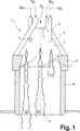
図1中に示された渦流発生器1,移行部材6及び後続する混合管8を有する予混合バーナーの縦断面に基づいて、水素又は水素を含む燃料がこの予混合バーナー内に供給されている時のこの予混合バーナー内で発生する理想的な流れ挙動を詳しく説明する。水素を供給するため、複数の供給管5が設けられている。図1中では、これらの供給管5のうちの2つの供給管だけが示されている。これらの供給管は、バーナー軸線Aの周りに同軸に配置されている。完璧を期する理由だけから、図2に関してその他の点で既に説明されている燃料を供給するもう1つの手段を短く引き合いに出す。したがって、液体燃料、特に石油BLを中央に配置された燃料ノズル3を通じて注入することが可能である。同様に、例えば天然ガスのような気体燃料BGの供給を空気流入スロット4に沿って設けられている燃料管を通じて可能にする。様々な燃料の種類の操作方法及び利用可能性に応じて、予混合バーナーにそれぞれの燃料を組み合わせて又は個々に供給し、これに応じて操作することが可能である。
Method of Implementing the Invention, Industrial Applicability Based on the longitudinal section of a premix burner having a vortex generator 1, a
説明した水素による予混合バーナーの運転に関しては、流れの勢いを有するそれぞれの水素流9を個々の供給管5を通じてバーナー1の内部に流入することが必要である。この流れの勢いの場合、バーナー内の流れ構造が十分に保持されている。この場合、同時に、水素流が、燃焼空気と可能な限り効率的に混合される。水素流が、バーナーから噴出した直後に、流れ形状が崩れる。その結果、流れ9に沿って生成された水素と空気の混合物が、分散して燃焼室内で完全に燃焼する。
With regard to the operation of the premixed burner with hydrogen as described, it is necessary for each
この流れの場合が、図1中に事例bで示されている。これに対して水素流9が、より大きい流れの勢いを提供する場合、すなわち水素流が、特により大きい流速で供給管5から燃焼室内に流入する場合、事例aで示されているように、流れ形状が、バーナーから流出した後も、すなわち燃焼室内でまだ保持されている。この場合、燃焼が、拡散の途中で燃焼する。この燃焼は、窒素酸化物の放出を増大させる。これに対して流れの勢いが非常に弱い場合、事例cで示されているように、水素流9が、バーナー内で崩れる。この場合、特に自己点火が、バーナー内で発生する。特にバーナー内の水素の滞在時間が非常に長い。しかも非常に弱い流れの勢いは、水素流の横からの僅かだけの浸入に起因して水素流と燃焼空気との混合を低減させる。
The case of this flow is shown by case b in FIG. On the other hand, if the
バーナー内に流入される水素流の流れ方向に指向する流れの勢いの上述した選択に加えて、水素と空気の混合物をバーナー軸線の周りに可能な限り空間的に均一に分散させることが同等に必要である。このため、図4a〜c中の表示にしたがって、水素供給用の供給管5が、渦流発生器1の渦流室を限定する渦流シェル2内に設けられている。供給管5の管径を、低カロリー燃料又は中カロリー燃料の今日まで知られた供給の場合よりも小さく形成することが基本的に必要である。図4a〜c中にはそれぞれ、渦流シェル2の部分横断面が示されている。供給管5の異なる配置が,この渦流シェル2内に設けられている。水素が、これらの供給管5を通じて渦流室内に供給される。図4a中には、4つの供給管5が設けられている。これらの供給管は、バーナー軸線Aに対して半径方向にも円周に沿っても異なって位置決めされている。図4bの実施の形態は、管の横断面に沿って小さく寸法決めされた複数の供給管5を提供する。これらの供給管5はそれぞれ、バーナー軸線Aの周りに同心円状に広範囲に配置されている。図4cの実施の形態は、異なる大きさに寸法決めした供給管5を選択している。この場合、半径方向の外側にある供給管5は、内側にある供給管5より大きい管の横断面を有する。その結果、水素の流量が、バーナー軸線Aに対して遠ざかるにつれて増大する。
In addition to the above-mentioned selection of flow momentum directed in the flow direction of the hydrogen stream entering the burner, it is equally possible to disperse the hydrogen and air mixture as spatially as possible around the burner axis. is necessary. For this reason, a
明らかに、それぞれの渦流シェル2内の供給管5のその他の構成及び配置も可能である。
水素流をそれぞれの供給管5から発生させるためには、特に適切なノズルを設けることが必要である。これらのノズルは、最も簡単な場合は簡単なオリフィスノズルとして又は適切なベンチュリノズル若しくは類似のノズル配置の形態で構成されている。したがって、例えば楕円、長方形又は三角形の流れ横断面を有する流れを作るため、適切なノズルを選択することによってバーナー内で発生する水素流の流れ形状に影響を与えることが可能である。水素流とこの水素流を包囲する燃焼空気との混合効率が、選択された流れ形状に応じて影響を受けて改良され得る。
Obviously, other configurations and arrangements of the
In order to generate a hydrogen stream from the
水素流と燃焼空気との混合を改良するもう1つの代わりの手段が、図5中に示されている。図5は、同様に渦流シェル2の部分横断面を示す。この渦流シェル内では、1つの供給管5が、複数の供給管の代わりに設けられている。供給管5は、半径成分rC及び/又は接線成分tCを有する。バーナー軸線Aに向かって指向する半径成分rCの場合、供給管5が、バーナー軸線Aに面して傾いている。その結果、供給管5から流出する燃料ジェットが、プリセット可能な半径角度αでバーナー軸線Aに対して傾斜している。同様に、半径成分rCをバーナー軸線Aに対して反対に設定することが可能である。この場合、供給管5から流出する水素ジェットが、燃焼軸線Aから傾いて指向されている。この場合、特に混合管の領域内のバーナーの側壁による水素流のウェッティングが発生しないように、傾斜角度を選択することが必要である。上述した半径成分と同様に、供給管5をバーナー軸線Aの周りの渦流シェル2の円周方向に沿っていわゆる接線角度だけ傾斜させることが可能である。特に、供給管5から流出する水素流が、バーナー軸線Aの周りの同じ渦流方向に流出するように、接線の傾斜が方向合わせされる。水素流と共に、燃焼空気も、空気流入スロット4を通じて渦流発生器1内に流入する。さらに、供給管から流出する水素流が、隣接している構成要素の側壁に対して直接悪影響を及ぼさないように、接線成分tC又は接線角度の設定も選択する必要がある。さらに、バーナー内に流出する水素流の平均滞在時間を過度に延ばさないことが重要である。同様に、接線成分をバーナー内の燃焼空気の渦流方向に対して反対に指向させることが考えられる。その結果、水素流が、反対方向の渦流の形態で渦流発生器内に供給される。こうして、水素と燃焼空気の混合度が著しく高まる。
Another alternative means of improving the mixing of the hydrogen stream and the combustion air is shown in FIG. FIG. 5 likewise shows a partial cross section of the
水素と燃焼空気との混合を向上させるもう1つの代わりの手段は、水素流に沿った渦Eを発生させる。図6中には、1つの供給管5が、その他の供給管を代表して示されている。水素流が、供給管5から流出する。この水素流は、時計回りに指向する渦E(矢印参照)を提供する。明らかに、渦Eの方向を反時計回りに適合させることが可能である。例えば銃身内に設けられているような、例えば供給管5内に螺旋状に延在する溝状の輪郭が、渦を生成するために使用される。渦に対応する流れを発生させる流れガイドベーンが、供給管5の流出口の領域内に設けられてもよい。水素流中に渦を発生させることによって、バーナー内の水素の最小限にすべき平均滞在時間を長くすることなしに、包囲する燃焼空気との横からの混合効率が、好ましい方法で明らかに改良され得る。多数の実験の結果、1より非常に小さいスワール比Ω、好ましくは0.5未満の渦を設定することが必要であることが分かっている。この場合、Ωは、接線に沿って働く流体モーメントの軸線方向の流れと軸線方向の流体モーメントの軸線方向の流れとの比である。この場合、渦崩壊が大幅に阻止される。
Another alternative means of improving the mixing of hydrogen and combustion air generates a vortex E along the hydrogen flow. In FIG. 6, one
図7a,b中には、水素流と包囲する燃焼空気との混合特性を改良する別の代わりの手段が示されている。この場合、供給管5は、環状部分11として形成されているか又は管の流出口に沿って環状の流出幾何構造を有する。水素流が、供給管5を通じて渦流発生器内に流入する。環状に生成される水素流の表面が、供給管5を通じて簡単なシングルオリフィス開口部から生成するような標準的な流れに比べて拡大され、その結果包囲する燃焼空気と効率的に混合することができる。
In FIGS. 7a and b another alternative means for improving the mixing characteristics of the hydrogen flow and the surrounding combustion air is shown. In this case, the
この点では、混合条件をさらに改良するこの環状の水素流が、水素流と燃焼空気との間の混合を改良する既に上述した手段と任意に組み合わせられ得ることが分かる。 In this respect, it can be seen that this annular hydrogen stream, which further improves the mixing conditions, can optionally be combined with the means already described above which improve the mixing between the hydrogen stream and the combustion air.
図7b中には、供給管5の流出領域の縦断面が示されている。楔状の押しのけ体10が、この流出領域内に収容されている。供給管5から流出する水素流が、この楔状の押しのけ体10によってプリセット可能な拡散で流出する。
In FIG. 7b, a longitudinal section of the outflow region of the
図8aの実施の形態では、供給管5の暗くハッチングした環状の領域11は、水素が流出する領域であることが分かる。明るい中央の円領域は、空気供給管に相当する。空気が、この空気供給管から流出される。この空気供給管は、環状の水素流によって包囲されている。図8bの実施の形態では、逆の場合が示されている。この場合、水素流の形態の水素が、内側にある明るい流れ領域から流出する。この水素流は、円形の環状空気流11によって包囲される。それぞれの空気流が供給管5のそれぞれの流れ領域から流出する速度を燃焼空気がバーナーを軸線方向に貫流する速度より大きく選択することが、特に好ましいと実証されている。バーナー内の水素の平均滞在時間が、この手段によって著しく低減でき、他方では混合率が改良され得る。
In the embodiment of FIG. 8a, it can be seen that the darkly hatched
混合率をさらに改良する手段が、均一な環状な流れの代わりにリング形に沿って配置された複数の小さい流路の配置を提供する。空気が、これらの流路を通じて流出し、環状の流れを作る。このリング状の流れは、リング形に対して中心に発生する水素流を円形に包囲する。 Means for further improving the mixing ratio provide an arrangement of a plurality of small channels arranged along a ring shape instead of a uniform annular flow. Air exits through these channels creating an annular flow. This ring-shaped flow encircles the hydrogen flow generated at the center with respect to the ring shape.
バーナーの内部に流出する水素流が、バーナーの構成要素の側壁に接触せず、特に側壁に近い境界層内の流速が低下し、これによってバーナー内の水素の平均滞在時間が上昇し、そして自己点火及びバックフラッシュの危険が同様に大きくなることは、予混合バーナーの内部に水素流を供給する上述した全ての可能性に対して共通である。 The hydrogen stream flowing out of the burner does not contact the sidewalls of the burner components, particularly the flow velocity in the boundary layer close to the sidewalls decreases, thereby increasing the average residence time of hydrogen in the burner and A similar increase in the risk of ignition and backflush is common to all the above mentioned possibilities of supplying a hydrogen flow inside the premix burner.
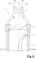
予混合バーナーに燃料としての水素を供給する上述した手段の好適な使用は、ガスタービン設備を駆動させる燃焼室の点火を提供する。全く一般に行われているガスタービン設備といわゆるガス化複合発電(IGCC,Integrated Gasification Combined Cycle)との組み合わせが、燃料を脱炭素処理する装置を一般に有する。水素リッチな燃料が、この装置によって得られる。この水素リッチな燃料は、解決手段にしたがう予混合バーナーに供給可能である。脱炭素処理の範囲内では、一般に30barだけの高い処理圧力,さらに約150℃以下の下で、同様に大量の窒素が増大する。この方法で水素の高い反応につながる危険を軽減するため、得られた窒素は、水素燃料に混合され得る。これに対しては、水素の反応度及び燃焼速度を著しく低減させるのに、混合すべき窒素の量が最小限で済む。このような運転方法では、特に対応して構成された図9中の予混合バーナーの示された縦断面から分かるように、窒素を添加した水素燃料混合物12を混合管8の領域内で燃焼軸線Aに対して半径方向に供給することが好ましいとさらに実証されている。この図9上では、既に記入された符号は、繰り返しを避けるためにさらに記入してない。流れの勢いが、窒素を水素燃料中に混合することによって高まる。これによって、混合領域内に半径方向に供給された窒素・水素流12が十分に侵入する。窒素・水素流12が、燃焼室に達する前に、この窒素・水素流12は、燃焼空気と完全に混合できる。さらに水素の反応度が、N2混合物によって著しく低減される。この代わりに又はH2の反応を低減する上述した手段と組み合わせて、接線方向の空気流入スロットを通じてバーナー内に流入する燃焼空気に窒素を混合することが考えられる。これによって、酸素成分が低減され、こうして水素の反応に影響する。さらに、空気を供給する代わりに図8a及びb中に記されている実施の形態でN2を供給することが考えられる。
The preferred use of the above-described means for supplying hydrogen as fuel to the premix burner provides ignition of the combustion chamber that drives the gas turbine equipment. A combination of gas turbine equipment and a so-called integrated gasification combined cycle (IGCC), which is quite common, generally has a device for decarbonizing the fuel. Hydrogen-rich fuel is obtained with this device. This hydrogen rich fuel can be supplied to a premix burner according to the solution. Within the scope of decarbonization treatment, large amounts of nitrogen increase as well, generally under high processing pressures of only 30 bar and even below about 150 ° C. In order to mitigate the risk of high hydrogen reactions in this way, the resulting nitrogen can be mixed with hydrogen fuel. In contrast, the amount of nitrogen to be mixed is minimized to significantly reduce the reactivity and burning rate of hydrogen. In such a method of operation, as can be seen from the longitudinal section of the premixing burner in FIG. 9 which is configured correspondingly, the
図10中の実施の形態から詳しく分かるように、水素の反応度及び燃焼速度を低減するもう1つの代わりの手段は、触媒反応の使用を提供する。図10b中に示されている触媒反応器13が、少なくとも1つの供給管5に沿って組み込まれている。水素が、この供給管5を通じて供給されて、予混合バーナー内で燃焼する。水素H2が、空気Lと共に供給管5に沿って混合装置14に供給される。混合物が、触媒反応器13内に流入する前に、この混合装置14は、流入する空気Lを水素H2と混合する。水H2Oが、水素の一部で発生する酸化の過程で生成される。この水H2Oは、空気中に含まれている窒素N2及び酸化しなかった水素H2と共に触媒反応器13から流出し、渦発生器15を通じて渦流発生器1内に達する。水素の反動活動が、触媒の経路内で生成された水蒸気によって及びN2との混合によって適切に影響される。これによって、バックフラッシュの危険が著しく低下する。さらに、触媒反応器13から渦流発生器1内に流入する燃料流が、バーナー内の燃焼空気を有する改良された混合特性を有する。したがって、濃い燃料の及び薄い燃料の燃焼系又は状態が、容易に制御及び監視することができる。
As can be seen in detail from the embodiment in FIG. 10, another alternative means of reducing hydrogen reactivity and combustion rate provides for the use of catalytic reactions. A
上述したバーナーの概念は、既存の液体燃料及び/又は気体燃料によるバーナーの運転に最適に適合されたバーナーの設計を変更することなしに、水素の燃焼を可能にし、既存の予混合バーナーシステムで簡単に適合することができる。水素又は水素を含む燃料を供給するために軸線方向に及び/又はバーナー軸線の周りに配置された供給管を設計し配置することに加えて、混合区間の長さの選択が、重要な設計パラメータである。一般に混合管は、バーナーの最大直径の1〜2倍の間にある長さを有する。予混合バーナーの運転モードに応じて、燃料の種類に調整された混合管の長さが、適切に最適にされて選択され得る。 The burner concept described above allows for the combustion of hydrogen without changing the design of the burner optimally adapted to the operation of the existing liquid and / or gaseous fuel burner, Can be easily adapted. In addition to designing and arranging supply pipes arranged axially and / or around the burner axis to supply hydrogen or hydrogen-containing fuels, the selection of the length of the mixing section is an important design parameter. It is. Generally, the mixing tube has a length that is between 1 and 2 times the maximum diameter of the burner. Depending on the operating mode of the premixing burner, the length of the mixing tube adjusted to the fuel type can be appropriately optimized and selected.
1 渦流発生器
2 渦流シェル
3 注入ノズル
4 空気流入スロット
5 供給管
6 移行部材
7 ガイドベーン
8 混合管
9 水素流
10 楔状の押しのけ体
11 環状部分
12 窒化水素燃料混合物
13 触媒反応器
14 混合装置
15 渦発生器
DESCRIPTION OF SYMBOLS 1 Eddy
Claims (16)
前記水素を含む又は水素から成る気体燃料が、前記バーナー軸線(A)に対してほぼ軸線方向に及び/又は同軸に空間的に広範囲に限定された流れ形状(9)を有し且つ流れの勢いを伴う燃料流を形成しながら前記渦流発生器(1)内に供給される結果、前記燃料流の前記流れ形状が、前記バーナー内で保持されていて、前記燃料流が、前記バーナーの流出口の領域内で崩れ、発生する逆流地帯の範囲内で着火に至ること、
水素を含む又は水素から成る前記気体燃料は、多数の個々の燃料流(9)の形態で、前記回転する燃焼空気流に対して半径方向に分布して前記渦流発生器(1)内に供給されること、及び
半径方向の内側にある燃料流(9)より大きい燃料流を有する半径方向の外側の燃料流が、前記渦流発生器(1)内に供給されることを特徴とする方法。A method of burning gaseous fuel containing or consisting of hydrogen by means of a burner, which provides a vortex generator (1), while the liquid fuel forms a conical jetted liquid fuel column the vortex generators (1) in the can be supplied along its central burner axis (a), the liquid fuel pillars, combustion air which rotates and flows into the vortex generators (1) in the tangential direction In such a method, surrounded and mixed by a flow ,
The gaseous fuel containing or consisting of hydrogen has a flow shape (9) that is spatially limited substantially axially and / or coaxially to the burner axis (A) and has a flow momentum. result supplied to the vortex generator (1) in while forming a fuel stream with said flow shape of the fuel flow, it said have been held in the burner, the fuel flow, the outlet of the burner Igniting within the area of the reverse flow zone that occurs ,
The gaseous fuel containing or consisting of hydrogen is distributed in the radial direction with respect to the rotating combustion air stream in the form of a number of individual fuel streams (9) and fed into the vortex generator (1). And
Method according to claim 1, characterized in that a radially outer fuel stream having a larger fuel stream than a radially inner fuel stream (9) is fed into said vortex generator (1) .
前記燃料流(9)は、円い流れ横断面を有し、この円い流れ横断面は、環状の空気流によって包囲されることを特徴とする請求項1〜5又は7のいずれか1項に記載の方法。 The fuel flow (9) has an annular flow cross section, which surrounds an inner air flow having the same flow direction with respect to the fuel flow; or
The fuel stream (9) has a rounded flow cross section, the circular flow cross section can be any one of claims 1 to 5 or 7, characterized in that it is surrounded by an annular air flow The method described in 1.
水素から成る前記燃料流(9)は、円い流れ横断面を有し、この円い流れ横断面は、環状のN2 の流れによって包囲されることを特徴とする請求項1〜8のいずれか1項に記載の方法。 The fuel stream comprising hydrogen (9) has an annular flow cross section, the flow cross section of the annular is to surround the flow of N 2 on the inside with the same flow direction with respect to the fuel flow , or the fuel stream comprising hydrogen (9) has a rounded flow cross section, according to claim 1-8 for the rounded flow cross-section, characterized in that it is surrounded by a flow of annular N 2 The method of any one of these.
水素を含む又は水素から成る前記気体燃料が、前記第3手段によって供給可能であること、
前記渦流発生器(1)は、個々の渦流シェル(2)から構成されていて、これらの渦流シェル(2)は対向して、前記渦流発生器(1)に対して接線方向に延在する前記空気流入スロット(4)を限定すること、
前記第3手段はそれぞれ、燃料管(5)として構成されていて、この燃料管(5)は、渦流シェル(2)に固定されていること、
複数のこのような燃料管(5)が、1つの渦流シェル(2)ごとに固定されていること、及び
1つの渦流シェル(2)ごとに設けられている燃料管(5)が、グループで又は個々に前記バーナー軸線(A)に対して異なる半径方向の間隔で配置されていて、前記バーナー軸線(A)に対してより大きい半径方向の距離を有する燃料管(5)が、前記バーナー軸線(A)に対してより近くにある燃料管(5)より大きい管径を有することを特徴とする装置。 A device for burning gaseous fuel containing or consisting of hydrogen by means of a burner, the burner comprising a vortex generator (1), means for supplying fuel and combustion air (L) in the vortex generator (1) A first means for supplying liquid fuel along the burner axis (A), and a second means along the air inlet slot (4) defined by the vortex generator (1) in the tangential direction. Two means and a third means are provided, and gaseous fuel is fed into the vortex generator (1) axially and / or coaxially with respect to the burner axis (A) by the third means. In the device that can be supplied,
The gaseous fuel comprising or consisting of hydrogen can be supplied by the third means;
The eddy current generator (1) is composed of individual eddy current shells (2), and these eddy current shells (2) face each other and extend in a tangential direction with respect to the eddy current generator (1). Limiting the air inlet slot (4);
The third means are each configured as a fuel pipe (5), the fuel pipe (5) being fixed to the vortex shell (2);
A plurality of such fuel tubes (5) being fixed per vortex shell (2), and
Fuel pipes (5) provided for each vortex shell (2) are arranged in groups or individually at different radial intervals with respect to the burner axis (A), so that the burner axis (A The fuel pipe (5) having a larger radial distance relative to the burner axis (A) has a larger pipe diameter than the fuel pipe (5) closer to the burner axis (A).
Applications Claiming Priority (3)
| Application Number | Priority Date | Filing Date | Title |
|---|---|---|---|
| CH1971/04 | 2004-11-30 | ||
| CH19712004 | 2004-11-30 | ||
| PCT/EP2005/055985 WO2006058843A1 (en) | 2004-11-30 | 2005-11-15 | Method and device for burning hydrogen in a premix burner |
Publications (3)
| Publication Number | Publication Date |
|---|---|
| JP2008522123A JP2008522123A (en) | 2008-06-26 |
| JP2008522123A5 JP2008522123A5 (en) | 2011-10-13 |
| JP4913746B2 true JP4913746B2 (en) | 2012-04-11 |
Family
ID=34974223
Family Applications (1)
| Application Number | Title | Priority Date | Filing Date |
|---|---|---|---|
| JP2007541942A Expired - Fee Related JP4913746B2 (en) | 2004-11-30 | 2005-11-15 | Method and apparatus for burning hydrogen in a premix burner |
Country Status (5)
| Country | Link |
|---|---|
| US (1) | US7871262B2 (en) |
| EP (1) | EP1817526B1 (en) |
| JP (1) | JP4913746B2 (en) |
| CN (1) | CN101069039B (en) |
| WO (1) | WO2006058843A1 (en) |
Families Citing this family (31)
| Publication number | Priority date | Publication date | Assignee | Title |
|---|---|---|---|---|
| CN101069039B (en) | 2004-11-30 | 2011-10-19 | 阿尔斯托姆科技有限公司 | Method and device for burning hydrogen in a premix burner |
| EP2058590B1 (en) | 2007-11-09 | 2016-03-23 | Alstom Technology Ltd | Method for operating a burner |
| WO2009068427A1 (en) * | 2007-11-27 | 2009-06-04 | Alstom Technology Ltd | Device and method for operating a gas turbine system using a second, hydrogen-rich fuel |
| WO2009068425A1 (en) * | 2007-11-27 | 2009-06-04 | Alstom Technology Ltd | Premix burner for a gas turbine |
| EP2220433B1 (en) | 2007-11-27 | 2013-09-04 | Alstom Technology Ltd | Method and device for burning hydrogen in a premix burner |
| EP2072899B1 (en) * | 2007-12-19 | 2016-03-30 | Alstom Technology Ltd | Fuel injection method |
| WO2009109448A1 (en) * | 2008-03-07 | 2009-09-11 | Alstom Technology Ltd | Burner arrangement, and use of such a burner arrangement |
| EP2257736B1 (en) | 2008-03-07 | 2015-11-25 | Alstom Technology Ltd | Method for the production of hot gas |
| JP5453322B2 (en) | 2008-03-07 | 2014-03-26 | アルストム テクノロジー リミテッド | Burner device and use of burner device |
| US8650881B2 (en) | 2009-06-30 | 2014-02-18 | General Electric Company | Methods and apparatus for combustor fuel circuit for ultra low calorific fuels |
| CH701905A1 (en) * | 2009-09-17 | 2011-03-31 | Alstom Technology Ltd | Method of burning hydrogen-rich, gaseous fuels in a burner and burner for carrying out the method. |
| US20120129111A1 (en) * | 2010-05-21 | 2012-05-24 | Fives North America Combustion, Inc. | Premix for non-gaseous fuel delivery |
| JPWO2012056750A1 (en) * | 2010-10-29 | 2014-03-20 | 有限会社T&K | Combustion method and combustion apparatus |
| US9134023B2 (en) * | 2012-01-06 | 2015-09-15 | General Electric Company | Combustor and method for distributing fuel in the combustor |
| JP5584260B2 (en) * | 2012-08-08 | 2014-09-03 | 日野自動車株式会社 | Exhaust purification device burner |
| US10837641B2 (en) | 2014-12-25 | 2020-11-17 | Kawasaki Jukogyo Kabushiki Kaisha | Burner, combustor, and gas turbine |
| US10890329B2 (en) | 2018-03-01 | 2021-01-12 | General Electric Company | Fuel injector assembly for gas turbine engine |
| CN108413444B (en) * | 2018-03-29 | 2023-11-21 | 中国科学院工程热物理研究所 | Premixing burner |
| CN109301291B (en) * | 2018-08-28 | 2021-05-11 | 中国北方发动机研究所(天津) | Exhaust hydrogen discharge structure for fuel cell, discharge system, and discharge control method |
| US10935245B2 (en) | 2018-11-20 | 2021-03-02 | General Electric Company | Annular concentric fuel nozzle assembly with annular depression and radial inlet ports |
| US11286884B2 (en) | 2018-12-12 | 2022-03-29 | General Electric Company | Combustion section and fuel injector assembly for a heat engine |
| US11073114B2 (en) | 2018-12-12 | 2021-07-27 | General Electric Company | Fuel injector assembly for a heat engine |
| US11156360B2 (en) | 2019-02-18 | 2021-10-26 | General Electric Company | Fuel nozzle assembly |
| CN109973993A (en) * | 2019-03-04 | 2019-07-05 | 深圳粤通新能源环保技术有限公司 | A kind of hydrogen, natural gas mix low-carbon combustion machine |
| WO2022076524A1 (en) * | 2020-10-06 | 2022-04-14 | Bloom Engineering Company, Inc. | Burner and method for hydrogen combustion with enhanced luminosity |
| DE102021103247A1 (en) | 2021-02-11 | 2022-08-11 | Vaillant Gmbh | Method and arrangement for reducing a combustion temperature during the combustion of hydrogen and air in a heater |
| US20220290862A1 (en) * | 2021-03-11 | 2022-09-15 | General Electric Company | Fuel mixer |
| CN113337321A (en) * | 2021-05-17 | 2021-09-03 | 西安交通大学 | Use of natural gas as hydrogen flame retardant and fuel suitable for oxyhydrogen burner |
| CN113847597B (en) * | 2021-09-14 | 2023-10-10 | 中国空气动力研究与发展中心空天技术研究所 | Gas fuel premixing cyclone particle generating device |
| DE102021210662A1 (en) * | 2021-09-24 | 2023-03-30 | Benninghoven Zweigniederlassung Der Wirtgen Mineral Technologies Gmbh | Device and method for drying material and asphalt mixing plant with such a device |
| CN114183772A (en) * | 2021-11-30 | 2022-03-15 | 哈尔滨工程大学 | High-efficient low emission combustor head that hydrogen mixes in advance |
Citations (5)
| Publication number | Priority date | Publication date | Assignee | Title |
|---|---|---|---|---|
| JPS537843A (en) * | 1976-07-10 | 1978-01-24 | Kawasaki Steel Corp | Combustion method of gas fuel in industrial furnace and combustion burner |
| JPS5652128A (en) * | 1979-09-29 | 1981-05-11 | Brother Ind Ltd | Tapping machine equipped with abnormallity detecting system |
| JPH07318018A (en) * | 1994-05-20 | 1995-12-08 | Abb Manag Ag | Operating method of premix burner |
| JPH11190504A (en) * | 1997-10-08 | 1999-07-13 | Abb Res Ltd | Burning method of gaseous, liquid, middle-calorie, or low-calorie fuel and burner for heat generator for effecting the same method |
| JP2000130757A (en) * | 1998-10-23 | 2000-05-12 | Hitachi Ltd | Gas turbine combustor for gasification power plant |
Family Cites Families (60)
| Publication number | Priority date | Publication date | Assignee | Title |
|---|---|---|---|---|
| JPS5535885A (en) * | 1978-09-06 | 1980-03-13 | Kobe Steel Ltd | Combustion method capable of minimizing production of nitrogen oxide and smoke |
| CH674561A5 (en) | 1987-12-21 | 1990-06-15 | Bbc Brown Boveri & Cie | |
| US6155212A (en) * | 1989-06-12 | 2000-12-05 | Mcalister; Roy E. | Method and apparatus for operation of combustion engines |
| US5044931A (en) * | 1990-10-04 | 1991-09-03 | Selas Corporation Of America | Low NOx burner |
| US5307634A (en) | 1992-02-26 | 1994-05-03 | United Technologies Corporation | Premix gas nozzle |
| DE4304213A1 (en) * | 1993-02-12 | 1994-08-18 | Abb Research Ltd | Burner for operating an internal combustion engine, a combustion chamber of a gas turbine group or a combustion system |
| CH687831A5 (en) * | 1993-04-08 | 1997-02-28 | Asea Brown Boveri | Premix burner. |
| DE4330083A1 (en) * | 1993-09-06 | 1995-03-09 | Abb Research Ltd | Method of operating a premix burner |
| US5415114A (en) * | 1993-10-27 | 1995-05-16 | Rjc Corporation | Internal air and/or fuel staged controller |
| US5500030A (en) * | 1994-03-03 | 1996-03-19 | Combustion Tec, Inc. | Oxy-gas fired forehearth burner system |
| DE4409918A1 (en) * | 1994-03-23 | 1995-09-28 | Abb Management Ag | Low calorific value fuel burner for combustion chamber |
| DE4426353A1 (en) * | 1994-07-25 | 1996-02-01 | Abb Research Ltd | burner |
| DE4435266A1 (en) * | 1994-10-01 | 1996-04-04 | Abb Management Ag | burner |
| DE4435473A1 (en) * | 1994-10-04 | 1996-04-11 | Abb Management Ag | Flame stabilised, premix burner for liq. fuel |
| US5516281A (en) * | 1995-02-06 | 1996-05-14 | Molodow; Marvin A. | Multiple jet burner |
| DE19527453B4 (en) * | 1995-07-27 | 2009-05-07 | Alstom | premix |
| CN1162089A (en) * | 1995-12-21 | 1997-10-15 | Abb研究有限公司 | Combustion device of heat generator |
| DE19547914A1 (en) * | 1995-12-21 | 1997-06-26 | Abb Research Ltd | Premix burner for a heat generator |
| DE19547913A1 (en) * | 1995-12-21 | 1997-06-26 | Abb Research Ltd | Burners for a heat generator |
| DE19547912A1 (en) * | 1995-12-21 | 1997-06-26 | Abb Research Ltd | Burners for a heat generator |
| DE19548853A1 (en) * | 1995-12-27 | 1997-07-03 | Abb Research Ltd | Cone burner |
| DE19610930A1 (en) * | 1996-03-20 | 1997-09-25 | Abb Research Ltd | Burners for a heat generator |
| DE19626240A1 (en) * | 1996-06-29 | 1998-01-02 | Abb Research Ltd | Premix burner and method of operating the burner |
| DE19639301A1 (en) * | 1996-09-25 | 1998-03-26 | Abb Research Ltd | Burner for operating a combustion chamber |
| US5954496A (en) * | 1996-09-25 | 1999-09-21 | Abb Research Ltd. | Burner for operating a combustion chamber |
| DE19640198A1 (en) * | 1996-09-30 | 1998-04-02 | Abb Research Ltd | Premix burner |
| DE19654116A1 (en) * | 1996-12-23 | 1998-06-25 | Abb Research Ltd | Burner for operating a combustion chamber with a liquid and / or gaseous fuel |
| ES2155663T3 (en) * | 1997-03-18 | 2001-05-16 | Alstom Power Schweiz Ag | PROCEDURE FOR THE OPERATION OF A BURNER STABILIZED BY TORBELLINOS, AS WELL AS A BURNER FOR THE PERFORMANCE OF THE PROCEDURE. |
| DE19721937B4 (en) * | 1997-05-26 | 2008-12-11 | Alstom | Premix burner for operating a unit for generating a hot gas |
| DE19736902A1 (en) * | 1997-08-25 | 1999-03-04 | Abb Research Ltd | Burners for a heat generator |
| ATE234444T1 (en) * | 1997-10-27 | 2003-03-15 | Alstom Switzerland Ltd | METHOD FOR OPERATING A PREMIX BURNER |
| DE59709446D1 (en) * | 1997-10-31 | 2003-04-10 | Alstom Switzerland Ltd | Burner for operating a heat generator |
| DE59710788D1 (en) * | 1997-11-13 | 2003-10-30 | Alstom Switzerland Ltd | Burner for operating a heat generator |
| EP0918190A1 (en) * | 1997-11-21 | 1999-05-26 | Abb Research Ltd. | Burner for the operation of a heat generator |
| DE59709281D1 (en) * | 1997-11-25 | 2003-03-13 | Alstom | Burner for operating a heat generator |
| DE19757189B4 (en) * | 1997-12-22 | 2008-05-08 | Alstom | Method for operating a burner of a heat generator |
| ATE237101T1 (en) * | 1998-01-23 | 2003-04-15 | Alstom Switzerland Ltd | BURNER FOR OPERATION OF A HEAT GENERATOR |
| DE59810284D1 (en) * | 1998-10-14 | 2004-01-08 | Alstom Switzerland Ltd | Burner for operating a heat generator |
| EP1002992B1 (en) * | 1998-11-18 | 2004-09-29 | ALSTOM Technology Ltd | Burner |
| DE19859829A1 (en) * | 1998-12-23 | 2000-06-29 | Abb Alstom Power Ch Ag | Burner for operating a heat generator |
| DE19914666B4 (en) * | 1999-03-31 | 2009-08-20 | Alstom | Burner for a heat generator |
| DE19917662C2 (en) * | 1999-04-19 | 2001-10-31 | Elco Kloeckner Heiztech Gmbh | Burners for liquid and / or gaseous fuel |
| DE59907942D1 (en) * | 1999-07-22 | 2004-01-15 | Alstom Switzerland Ltd | premix |
| EP1070915B1 (en) | 1999-07-22 | 2004-05-19 | ALSTOM Technology Ltd | Premix burner |
| AU2001272682A1 (en) * | 2000-06-15 | 2001-12-24 | Alstom Power N.V. | Method for operating a burner and burner with stepped premix gas injection |
| US20020064738A1 (en) * | 2000-07-11 | 2002-05-30 | Hugens John R. | Method and apparatus for furnace air supply enrichment |
| US6729874B2 (en) * | 2000-07-27 | 2004-05-04 | John Zink Company, Llc | Venturi cluster, and burners and methods employing such cluster |
| DE10042315A1 (en) * | 2000-08-29 | 2002-03-14 | Alstom Power Nv | Burner for heat generator comprises three injectors for gaseous or liquid fuel, swirl generator, mixing section , and transfer ducts |
| DE10050248A1 (en) * | 2000-10-11 | 2002-04-18 | Alstom Switzerland Ltd | Pre-mixing burner comprises swirl burner with inner chamber, with widening passage, injector with adjustable elements. |
| DE10055408A1 (en) * | 2000-11-09 | 2002-05-23 | Alstom Switzerland Ltd | Process for fuel injection into a burner |
| DE10061527A1 (en) * | 2000-12-11 | 2002-06-13 | Alstom Switzerland Ltd | Premix burner assembly with catalytic combustion and method of operation therefor |
| DE10061526A1 (en) * | 2000-12-11 | 2002-06-20 | Alstom Switzerland Ltd | Premix burner arrangement for operating a combustion chamber |
| DE10064259B4 (en) * | 2000-12-22 | 2012-02-02 | Alstom Technology Ltd. | Burner with high flame stability |
| EP1255080B1 (en) * | 2001-04-30 | 2008-09-03 | ALSTOM Technology Ltd | Catalytic burner |
| DE50212753D1 (en) * | 2001-07-26 | 2008-10-23 | Alstom Technology Ltd | Premix burner with high flame stability |
| US6790030B2 (en) * | 2001-11-20 | 2004-09-14 | The Regents Of The University Of California | Multi-stage combustion using nitrogen-enriched air |
| DE10164099A1 (en) * | 2001-12-24 | 2003-07-03 | Alstom Switzerland Ltd | Burner with staged fuel injection |
| US6773256B2 (en) * | 2002-02-05 | 2004-08-10 | Air Products And Chemicals, Inc. | Ultra low NOx burner for process heating |
| DE10233161B4 (en) * | 2002-07-22 | 2012-01-05 | Alstom Technology Ltd. | Burner and pilot burner |
| CN101069039B (en) | 2004-11-30 | 2011-10-19 | 阿尔斯托姆科技有限公司 | Method and device for burning hydrogen in a premix burner |
-
2005
- 2005-11-15 CN CN2005800410039A patent/CN101069039B/en not_active Expired - Fee Related
- 2005-11-15 EP EP05821548.4A patent/EP1817526B1/en not_active Not-in-force
- 2005-11-15 JP JP2007541942A patent/JP4913746B2/en not_active Expired - Fee Related
- 2005-11-15 WO PCT/EP2005/055985 patent/WO2006058843A1/en active Application Filing
-
2007
- 2007-05-23 US US11/752,359 patent/US7871262B2/en active Active
Patent Citations (5)
| Publication number | Priority date | Publication date | Assignee | Title |
|---|---|---|---|---|
| JPS537843A (en) * | 1976-07-10 | 1978-01-24 | Kawasaki Steel Corp | Combustion method of gas fuel in industrial furnace and combustion burner |
| JPS5652128A (en) * | 1979-09-29 | 1981-05-11 | Brother Ind Ltd | Tapping machine equipped with abnormallity detecting system |
| JPH07318018A (en) * | 1994-05-20 | 1995-12-08 | Abb Manag Ag | Operating method of premix burner |
| JPH11190504A (en) * | 1997-10-08 | 1999-07-13 | Abb Res Ltd | Burning method of gaseous, liquid, middle-calorie, or low-calorie fuel and burner for heat generator for effecting the same method |
| JP2000130757A (en) * | 1998-10-23 | 2000-05-12 | Hitachi Ltd | Gas turbine combustor for gasification power plant |
Also Published As
| Publication number | Publication date |
|---|---|
| JP2008522123A (en) | 2008-06-26 |
| EP1817526B1 (en) | 2019-03-20 |
| EP1817526A1 (en) | 2007-08-15 |
| WO2006058843A1 (en) | 2006-06-08 |
| US20080280239A1 (en) | 2008-11-13 |
| CN101069039B (en) | 2011-10-19 |
| US7871262B2 (en) | 2011-01-18 |
| CN101069039A (en) | 2007-11-07 |
Similar Documents
| Publication | Publication Date | Title |
|---|---|---|
| JP4913746B2 (en) | Method and apparatus for burning hydrogen in a premix burner | |
| JP2008522123A5 (en) | ||
| JP5594951B2 (en) | Burner operation method | |
| JP2713627B2 (en) | Gas turbine combustor, gas turbine equipment including the same, and combustion method | |
| US6461147B1 (en) | Gas Burner | |
| US8959922B2 (en) | Fuel nozzle with flower shaped nozzle tube | |
| JP5399462B2 (en) | Method for operating the burner device | |
| US20090249789A1 (en) | Burner tube premixer and method for mixing air and gas in a gas turbine engine | |
| KR102281567B1 (en) | Hydrogen gas burner for flashback prevention | |
| JP4799413B2 (en) | Combustion method and apparatus for performing the combustion method | |
| JP2020038038A (en) | Gas turbine combustor | |
| JP2010048542A (en) | Lean direct injection diffusion chip and related method | |
| EP2116767A1 (en) | Burner with lance | |
| JP2006017453A (en) | Multi-stage combustion system having ignition support fuel lance | |
| JP2011504995A (en) | Method and apparatus for burning hydrogen in a premix burner | |
| RU2494310C1 (en) | Burner device for combustion of industrial wastes | |
| JP4499734B2 (en) | Fuel combustion method and apparatus | |
| KR100679596B1 (en) | Radial inflow dual fuel injector | |
| JP3139978B2 (en) | Gas turbine combustor | |
| CN115451433A (en) | Fuel nozzle premixing system for gas turbine combustor | |
| JPH08261417A (en) | Pre-mixing burner | |
| JP2008214163A (en) | Combustible gas mixing method and mixer | |
| CA2280169A1 (en) | Fuel combustion device and method | |
| JP4597986B2 (en) | Fluid fuel burner | |
| KR20210034334A (en) | A Low-NOx combustor capable of internal recirculation of flue gas by using venturi effect through improvement of burner structure |
Legal Events
| Date | Code | Title | Description |
|---|---|---|---|
| A621 | Written request for application examination |
Free format text: JAPANESE INTERMEDIATE CODE: A621 Effective date: 20080925 |
|
| RD04 | Notification of resignation of power of attorney |
Free format text: JAPANESE INTERMEDIATE CODE: A7424 Effective date: 20100519 |
|
| A977 | Report on retrieval |
Free format text: JAPANESE INTERMEDIATE CODE: A971007 Effective date: 20110422 |
|
| A131 | Notification of reasons for refusal |
Free format text: JAPANESE INTERMEDIATE CODE: A131 Effective date: 20110531 |
|
| A524 | Written submission of copy of amendment under section 19 (pct) |
Free format text: JAPANESE INTERMEDIATE CODE: A524 Effective date: 20110825 |
|
| TRDD | Decision of grant or rejection written | ||
| A01 | Written decision to grant a patent or to grant a registration (utility model) |
Free format text: JAPANESE INTERMEDIATE CODE: A01 Effective date: 20120110 |
|
| A01 | Written decision to grant a patent or to grant a registration (utility model) |
Free format text: JAPANESE INTERMEDIATE CODE: A01 |
|
| A61 | First payment of annual fees (during grant procedure) |
Free format text: JAPANESE INTERMEDIATE CODE: A61 Effective date: 20120119 |
|
| R150 | Certificate of patent or registration of utility model |
Ref document number: 4913746 Country of ref document: JP Free format text: JAPANESE INTERMEDIATE CODE: R150 Free format text: JAPANESE INTERMEDIATE CODE: R150 |
|
| FPAY | Renewal fee payment (event date is renewal date of database) |
Free format text: PAYMENT UNTIL: 20150127 Year of fee payment: 3 |
|
| R250 | Receipt of annual fees |
Free format text: JAPANESE INTERMEDIATE CODE: R250 |
|
| R250 | Receipt of annual fees |
Free format text: JAPANESE INTERMEDIATE CODE: R250 |
|
| S533 | Written request for registration of change of name |
Free format text: JAPANESE INTERMEDIATE CODE: R313533 |
|
| R350 | Written notification of registration of transfer |
Free format text: JAPANESE INTERMEDIATE CODE: R350 |
|
| R250 | Receipt of annual fees |
Free format text: JAPANESE INTERMEDIATE CODE: R250 |
|
| S111 | Request for change of ownership or part of ownership |
Free format text: JAPANESE INTERMEDIATE CODE: R313113 |
|
| R350 | Written notification of registration of transfer |
Free format text: JAPANESE INTERMEDIATE CODE: R350 |
|
| R250 | Receipt of annual fees |
Free format text: JAPANESE INTERMEDIATE CODE: R250 |
|
| LAPS | Cancellation because of no payment of annual fees |