JP4913552B2 - Image forming apparatus - Google Patents
Image forming apparatus Download PDFInfo
- Publication number
- JP4913552B2 JP4913552B2 JP2006301683A JP2006301683A JP4913552B2 JP 4913552 B2 JP4913552 B2 JP 4913552B2 JP 2006301683 A JP2006301683 A JP 2006301683A JP 2006301683 A JP2006301683 A JP 2006301683A JP 4913552 B2 JP4913552 B2 JP 4913552B2
- Authority
- JP
- Japan
- Prior art keywords
- transfer material
- transfer
- forming apparatus
- image forming
- contact portion
- Prior art date
- Legal status (The legal status is an assumption and is not a legal conclusion. Google has not performed a legal analysis and makes no representation as to the accuracy of the status listed.)
- Expired - Fee Related
Links
Images


Landscapes
- Paper Feeding For Electrophotography (AREA)
- Electrophotography Configuration And Component (AREA)
- Electrostatic Charge, Transfer And Separation In Electrography (AREA)
- Control Or Security For Electrophotography (AREA)
Description
本発明は、電子写真式複写装置、プリンタ、ファクシミリ、複合機等の画像形成装置に関し、詳しくは複数の画像が転写される中間転写体を有する画像形成装置に関する。 The present invention relates to an image forming apparatus such as an electrophotographic copying apparatus, a printer, a facsimile machine, or a multifunction machine, and more particularly to an image forming apparatus having an intermediate transfer body to which a plurality of images are transferred.
電子写真式複写装置、プリンタ、ファクシミリ、複合機等の画像形成装置において、中間転写体である中間転写ベルト上に複数の画像を重ね合わせて1次転写し、この1次転写された画像を転写材上に2次転写して画像を得る画像形成装置が、例えば「特許文献1」に開示されている。 In an image forming apparatus such as an electrophotographic copying machine, a printer, a facsimile machine, or a multifunction machine, a plurality of images are superimposed on an intermediate transfer belt, which is an intermediate transfer body, to perform primary transfer, and the primary transferred image is transferred. An image forming apparatus that obtains an image by secondary transfer onto a material is disclosed in, for example, “Patent Document 1”.
上述した画像形成装置において、中間転写ベルト上の1次転写画像を転写材上に2次転写する場合、転写材は中間転写ベルト及びこれと接触配置された2次転写ローラとの間を通過するが、転写材が中間転写ベルトと2次転写ローラとの接触部に進入する際に、転写材が進入することにより負荷が生じて中間転写ベルトの走行が不安点となる。 In the image forming apparatus described above, when the primary transfer image on the intermediate transfer belt is secondarily transferred onto the transfer material, the transfer material passes between the intermediate transfer belt and the secondary transfer roller disposed in contact therewith. However, when the transfer material enters the contact portion between the intermediate transfer belt and the secondary transfer roller, a load is generated due to the transfer material entering, causing the intermediate transfer belt to run.
従来の画像形成装置においては、中間転写ベルトを走行させる駆動ローラの回転数をエンコーダ等の検出器で検出し、駆動ローラを回転駆動する回転駆動手段をフィードバック制御することにより中間転写ベルトを安定して走行させているが、上述した転写材の進入による負荷変動が急激であってフィードバック制御が間に合わず、中間転写ベルトの走行が不安定となったときに中間転写ベルト上に1次転写画像が転写されると色ずれ及び位置ずれ等が生じてしまい、良好な画像が得られなくなってしまうという問題点がある。最近では装置の小型化に伴い、転写材を一時停止させるレジストローラ対と2次転写部との距離が接近する傾向にあるため、転写材進入時における負荷及び衝撃が大きくなる傾向にある。 In a conventional image forming apparatus, the rotational speed of a driving roller that runs the intermediate transfer belt is detected by a detector such as an encoder, and the rotational driving means that rotationally drives the driving roller is feedback-controlled to stabilize the intermediate transfer belt. However, when the load fluctuation due to the entrance of the transfer material described above is sudden and the feedback control is not in time, and the running of the intermediate transfer belt becomes unstable, the primary transfer image is formed on the intermediate transfer belt. When transferred, there is a problem in that color misregistration, positional misalignment, and the like occur, and a good image cannot be obtained. Recently, with the miniaturization of the apparatus, the distance between the pair of registration rollers for temporarily stopping the transfer material and the secondary transfer portion tends to approach, so that the load and impact when entering the transfer material tend to increase.
本発明は上述の問題点を解決し、2次転写時における転写材進入に伴う負荷を低減し、良好な画像形成を継続して行うことが可能な画像形成装置の提供を目的とする。 SUMMARY An advantage of some aspects of the invention is to provide an image forming apparatus capable of solving the above-described problems, reducing a load caused by entering a transfer material during secondary transfer, and continuously performing good image formation.
請求項1記載の発明は、像担持体と、前記像担持体上のトナー像が1次転写される中間転写体と、前記中間転写体に接触配置され前記中間転写体上の1次転写画像を転写材上に2次転写する2次転写手段とを有する画像形成装置において、前記中間転写体と前記2次転写手段との接触部に前記転写材が進入する際に、前記転写材の搬送方向先端縁が前記接触部に対して非平行状態で進入する画像形成装置であって、前記接触部の形状が前記転写材の搬送方向及び厚み方向に向けて湾曲形成されていることを特徴とする。
According to the first aspect of the present invention, there is provided an image carrier, an intermediate transfer member on which a toner image on the image carrier is primarily transferred, and a primary transfer image on the intermediate transfer member arranged in contact with the intermediate transfer member. In the image forming apparatus having a secondary transfer unit that secondary-transfers the toner onto the transfer material, the transfer material is transported when the transfer material enters the contact portion between the intermediate transfer member and the secondary transfer unit. An image forming apparatus in which a leading edge in a direction enters in a non-parallel state with respect to the contact portion, wherein the shape of the contact portion is formed to be curved toward a transfer direction and a thickness direction of the transfer material. To do.
請求項2記載の発明は、請求項1記載の画像形成装置において、さらに前記接触部において前記中間転写体を支持する転写体支持体と2次転写手段とがそれぞれ回転体により構成され、前記各回転体はその一方が回転軸方向に鼓形状を呈し他方が回転軸方向に太鼓形状を呈すると共に鼓形状の曲凹部と太鼓形状の曲凸部とが異なる曲率で互いに対向配置された弾性体からなり、前記中間転写体を介して互いに圧接配置されていとを特徴とする。 According to a second aspect of the present invention, in the image forming apparatus according to the first aspect, the transfer body support and the secondary transfer means for supporting the intermediate transfer body at the contact portion are each constituted by a rotating body, elastic one of the rotating body Waso are opposed to each other in Kyokutotsu portion is different from the curvature of the song recess and drum shape of hourglass shape with coloration by the other exhibits a drum shape in the rotation axis direction hourglass shape in the rotation axis direction And are arranged in pressure contact with each other via the intermediate transfer member.
請求項3記載の発明は、請求項2記載の画像形成装置において、前記転写体支持体が太鼓形状を呈することを特徴とする。 According to a third aspect of the present invention, in the image forming apparatus according to the second aspect, the transfer member support has a drum shape .
本発明によれば、転写材の搬送方向先端縁が接触部に対して非平行状態で進入することにより接触部進入時における負荷が軽減され、中間転写体の走行が不安定となることが防止されて良好な画像を継続して得ることができる。 According to the present invention, the leading edge of the transfer material in the conveyance direction enters in a non-parallel state with respect to the contact portion, thereby reducing the load when the contact portion enters and preventing the running of the intermediate transfer member from becoming unstable. As a result, good images can be obtained continuously.
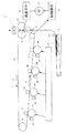
図1は、本発明の一実施形態を採用した画像形成装置の概略構成図である。同図においてフルカラー電子写真式複写装置である画像形成装置1は、イエロ、シアン、マゼンタ、ブラックの各色に対応した4個の像担持体2Y,2C,2M,2Kを有しており、各像担持体2Y,2C,2M,2Kの周囲には、各像担持体2Y,2C,2M,2Kの周面を帯電させる図示しない帯電装置、各像担持体2Y,2C,2M,2Kの周面上に形成された静電潜像を現像して各像担持体2Y,2C,2M,2Kの周面上にトナー像を形成する現像ユニット3Y,3C,3M,3K、各像担持体2Y,2C,2M,2Kの周面を除電する図示しない除電装置、各像担持体2Y,2C,2M,2Kの周面をクリーニングする図示しないクリーニング装置等が配置されている。各像担持体2Y,2C,2M,2Kの下方には、帯電された各像担持体2Y,2C,2M,2Kの周面に対し各色に対応した光を照射して静電潜像を形成する露光装置4が配置されている。
FIG. 1 is a schematic configuration diagram of an image forming apparatus employing an embodiment of the present invention. In FIG. 1, an image forming apparatus 1 which is a full-color electrophotographic copying apparatus has four
各像担持体2Y,2C,2M,2Kの上方には、転写体支持体である駆動ローラ5、テンションローラ6、従動ローラ7に掛け渡され、駆動ローラ5が減速ギヤ8を介して駆動モータ9によって回転駆動されることにより矢印A方向に走行する中間転写体としての中間転写ベルト10が配置されている。中間転写ベルト10は、駆動モータ9がその作動を制御装置16によって制御されることによりその走行を制御される。中間転写ベルト10を介して各像担持体2Y,2C,2M,2Kと対向する位置には、各像担持体2Y,2C,2M,2Kの周面上に形成された各トナー像を中間転写ベルト10上に1次転写して中間転写ベルト10上に1次転写画像を形成する1次転写ローラ11Y,11C,11M,11Kが配置されている。中間転写ベルト10を介して駆動ローラ5と対向する位置には、中間転写ベルト10上に形成された1次転写画像を転写材上に2次転写する2次転写手段としての2次転写ローラ12が配置されている。2次転写ローラ12は所定の圧接力で中間転写ベルト10に圧接されており、両者の圧接部において接触部Bが構成されている。
Above each of the
露光装置4の下方には多数の転写材Pを貯容する給紙部としての給紙カセット13が配置されており、給紙カセット13は画像形成装置1の図示しない装置本体に対して着脱可能に構成されている。給紙カセット13の本体装着位置の上方には、給紙カセット13内から転写材Pを給送する給紙ローラ14が配置されており、給紙ローラ14と接触部Bとの間の転写材給送経路上には、転写材Pを一時停止させた後に所定のタイミングで接触部Bに向けて給送するレジストローラ対15が配置されている。接触部Bの転写材搬送方向下流側には、2次転写された2次転写画像を転写材P上に定着させる定着装置17が配置されている。
A
上述の構成より、画像形成装置1の動作を以下に説明する。
画像形成動作が開始されると、各像担持体2Y,2C,2M,2Kが図1においてそれぞれ時計回りに回転し、その表面が図示しない帯電装置によってそれぞれ一様に帯電される。その後、各像担持体2Y,2C,2M,2Kの帯電面に露光装置4よりイエロ、マゼンタ、シアン、ブラックの各色に対応した光が照射され、各像担持体2Y,2C,2M,2Kの表面に静電潜像がそれぞれ形成される。形成された各静電潜像は各現像ユニット3Y,3C,3M,3Kにより現像されてイエロ、マゼンタ、シアン、ブラックのトナー像となり、各トナー像は各1次転写ローラ11Y,11C,11M,11Kによって正確に重ね合わされた状態で中間転写ベルト10上に1次転写され、中間転写ベルト10上にはフルカラーの合成カラー画像である1次転写画像が形成される。
The operation of the image forming apparatus 1 will be described below with the above configuration.
When the image forming operation is started, the
一方、給紙ローラ14の作動により給紙カセット13内から転写材Pが給送され、給送された転写材Pはレジストローラ対15において一時停止された後、所定のタイミングで接触部Bに向けて給送される。接触部Bに送り込まれた転写材Pは、2次転写ローラ12によって中間転写ベルト10上の1次転写画像を一括して2次転写され、その上面に合成カラー画像である2次転写画像を転写される。画像を転写された転写材Pは、定着装置17を通過する際に2次転写画像を定着された後、図示しない排紙トレイ上に排出される。
On the other hand, the transfer material P is fed from the inside of the
上述の画像形成動作時において、「発明が解決しようとする課題」の欄にも記載したように、転写材Pが接触部Bに進入する際に負荷が生じて中間転写ベルト10の走行が不安定となり、このときに中間転写ベルト10上に1次転写画像が転写されると色ずれ及び位置ずれ等が生じてしまい、良好な画像が得られなくなってしまうという問題点がある。この問題点を解決するため、本発明では図2に示すように、転写材Pの搬送方向先端縁P1が接触部Bに対して非平行状態で進入するように構成している。以下に具体例を説明する。
During the image forming operation described above, as described in the column “Problems to be Solved by the Invention”, a load is generated when the transfer material P enters the contact portion B, and the
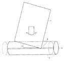
図3は、本発明の第1の実施形態を示している。この第1の実施形態では、図1に示した画像形成装置1において、駆動ローラ5をアスカーC硬度で50〜60度程度の弾性体により構成し、その形状を太鼓状としている。図3に示した状態では、中間転写ベルト10を介して駆動ローラ5と2次転写ローラ12とは圧接されておらず、両者を図4に示すように圧接して配置する。
FIG. 3 shows a first embodiment of the present invention. In the first embodiment, in the image forming apparatus 1 shown in FIG. 1, the
上述の構成とすることにより、中間転写ベルト10を介した駆動ローラ5と2次転写ローラ12との圧接力はその中央部が両端部に比して高くなり、接触部Bの形状がその中央部において転写材搬送方向に伸びた湾曲形状を呈することにより、転写材Pはその中央部から接触部Bに進入し、中央部に続いて両端部が接触部Bに進入することとなり、転写材Pの搬送方向先端縁P1が接触部Bに対して非平行状態で進入することにより接触部進入時における負荷が軽減され、中間転写ベルト10の走行が不安定となることが防止されて良好な画像を継続して得ることができる。
With the above-described configuration, the pressure contact force between the
第1の実施形態では、駆動ローラ5を弾性体からなる太鼓形状として2次転写ローラ12を円筒形状としたが、駆動ローラ5を円筒形状として2次転写ローラ12を太鼓形状とする構成、駆動ローラ5及び2次転写ローラ12を共に太鼓形状とする構成、2次転写ローラ12を弾性体により構成する構成としても同様の作用効果を得ることができる。上述の構成において駆動ローラ5を太鼓形状とすることにより、中間転写ベルト10を駆動ローラ5の中央部に寄せて駆動ローラ5からの中間転写ベルト10の脱落を防止する作用効果を得ることができる。
In the first embodiment, the
図5は、本発明の第2の実施形態を示している。この第2の実施形態では、図1に示した画像形成装置1において、駆動ローラ5をアスカーC硬度で50〜60度程度の弾性体により構成し、その形状を鼓状としている。図5に示した状態では、中間転写ベルト10を介して駆動ローラ5と2次転写ローラ12とは圧接されておらず、両者を図6に示すように圧接して配置する。
FIG. 5 shows a second embodiment of the present invention. In the second embodiment, in the image forming apparatus 1 shown in FIG. 1, the
上述の構成とすることにより、中間転写ベルト10を介した駆動ローラ5と2次転写ローラ12との圧接力はその両端部が中央部に比して高くなり、接触部Bの形状がその両端部において転写材搬送方向に伸びた湾曲形状を呈することにより、転写材Pはその両端部から接触部Bに進入し、両端部に続いて中央部が接触部Bに進入することとなり、転写材Pの搬送方向先端縁P1が接触部Bに対して非平行状態で進入することにより接触部進入時における負荷が軽減され、中間転写ベルト10の走行が不安定となることが防止されて良好な画像を継続して得ることができる。
With the above-described configuration, the pressure contact force between the driving
第2の実施形態では、駆動ローラ5を弾性体からなる鼓形状として2次転写ローラ12を円筒形状としたが、駆動ローラ5を円筒形状として2次転写ローラ12を鼓形状とする構成、駆動ローラ5及び2次転写ローラ12を共に鼓形状とする構成、2次転写ローラ12を弾性体により構成する構成としても同様の作用効果を得ることができる。
In the second embodiment, the
図7は、本発明の第3の実施形態を示している。この第3の実施形態では、図1に示した画像形成装置1において、駆動ローラ5をアスカーC硬度で50〜60度程度の弾性体により構成してその形状を太鼓状とすると共に、2次転写ローラ12を鼓形状として駆動ローラ5及び2次転写ローラ12の曲率が互いに同じとなるように構成し、中間転写ベルト10を介して両者を圧接配置している。
FIG. 7 shows a third embodiment of the present invention. In the third embodiment, in the image forming apparatus 1 shown in FIG. 1, the
上述の構成とすることにより、接触部Bの形状が転写材Pの厚み方向に湾曲した形状を呈することにより、転写材Pの搬送方向先端縁P1が接触部Bに対して非平行状態で進入することにより接触部進入時における負荷が軽減され、中間転写ベルト10の走行が不安定となることが防止されて良好な画像を継続して得ることができる。
With the above-described configuration, the shape of the contact portion B is curved in the thickness direction of the transfer material P, so that the leading edge P1 in the transport direction of the transfer material P enters the contact portion B in a non-parallel state. By doing so, the load at the time of entering the contact portion is reduced, the running of the
第3の実施形態では、駆動ローラ5を弾性体からなる太鼓形状として2次転写ローラ12を鼓形状としたが、駆動ローラ5を鼓形状として2次転写ローラ12を太鼓形状とする構成、2次転写ローラ12を弾性体により構成する構成としても同様の作用効果を得ることができる。上述の構成において駆動ローラ5を太鼓形状とすることにより、中間転写ベルト10を駆動ローラ5の中央部に寄せて駆動ローラ5からの中間転写ベルト10の脱落を防止する作用効果を得ることができる。
In the third embodiment, the
第3の実施形態の変形例として、駆動ローラ5及び2次転写ローラ12の曲率が互いに異なるように構成し、中間転写ベルト10を介して両者を圧接配置する構成としてもよい。このような構成とすれば、曲率の差に応じて接触部Bの形状を転写材の厚み方向及び転写材搬送方向の双方に湾曲した形状とすることができ、転写材Pの搬送方向先端縁P1が接触部Bに対して非平行状態で進入することにより接触部進入時における負荷が軽減され、中間転写ベルト10の走行が不安定となることが防止されて良好な画像を継続して得ることができる。
As a modified example of the third embodiment, the driving
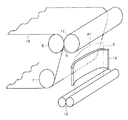
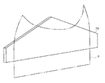
図8は、本発明の第4の実施形態を示している。この第4の実施形態では、図1に示した画像形成装置1において、駆動ローラ5及び2次転写ローラ12を共に円筒形状とすると共に、レジストローラ対15と接触部Bとの間の位置に、転写材搬送方向における右側部18aの長さが同左側部18bの長さよりも長く形成された平面視台形状のガイド部材18を有している。
FIG. 8 shows a fourth embodiment of the present invention. In the fourth embodiment, in the image forming apparatus 1 shown in FIG. 1, the
上述の構成とすることにより、転写材Pの左側縁部がガイド部材18の左側部18bを抜けた後も転写材Pの右側縁部はガイド部材18の右側部18aによってガイドされているため、転写材Pの左側縁部のみがガイド部材18の奥側に向かって倒れ、転写材Pの搬送方向先端縁P1が接触部Bに対して非平行状態で進入することにより接触部進入時における負荷が軽減され、中間転写ベルト10の走行が不安定となることが防止されて良好な画像を継続して得ることができる。
With the above-described configuration, the right side edge of the transfer material P is guided by the
図9は、本発明の第5の実施形態を示している。この第5の実施形態では、図1に示した画像形成装置1において、駆動ローラ5及び2次転写ローラ12を共に円筒形状とすると共に、レジストローラ対15と接触部Bとの間の位置に、転写材Pの厚み方向に湾曲形成されたガイド部材19を有している。
FIG. 9 shows a fifth embodiment of the present invention. In the fifth embodiment, in the image forming apparatus 1 shown in FIG. 1, the
上述の構成とすることにより、レジストローラ対15より給送された転写材Pはガイド部材19によってその厚み方向に湾曲した状態で接触部Bに進入するため、転写材Pの搬送方向先端縁P1が接触部Bに対して非平行状態で進入することにより接触部進入時における負荷が軽減され、中間転写ベルト10の走行が不安定となることが防止されて良好な画像を継続して得ることができる。
With the above-described configuration, the transfer material P fed from the
図10は、本発明の第6の実施形態を示している。この第6の実施形態は、第4の実施形態と比較すると、ガイド部材18に代えてガイド部材20を用いた点においてのみ相違しており、他の構成は同一である。ガイド部材20は、転写材Pの幅方向における形状が左右対称であると共に中央部の転写材搬送方向長さが両端部の転写材搬送方向長さよりも長い平面視山型形状を呈している。
FIG. 10 shows a sixth embodiment of the present invention. The sixth embodiment is different from the fourth embodiment only in that a
上述の構成とすることにより、転写材Pの両側縁部がガイド部材20の両側部を抜けた後も転写材Pの中央部はガイド部材20によってガイドされているため、転写材Pの両側縁部がガイド部材20の奥側に向かって倒れ、転写材Pの搬送方向先端縁P1が接触部Bに対して非平行状態で進入することにより接触部進入時における負荷が軽減され、中間転写ベルト10の走行が不安定となることが防止されて良好な画像を継続して得ることができる。
With the above-described configuration, since the central portion of the transfer material P is guided by the
図11は、本発明の第7の実施形態を示している。この第7の実施形態は、第4の実施形態と比較すると、ガイド部材18に代えてガイド部材21を用いた点においてのみ相違しており、他の構成は同一である。ガイド部材21は、転写材Pの幅方向における形状が左右非対称であると共に中央部の転写材搬送方向長さが両端部の転写材搬送方向長さよりも短い平面視谷型形状を呈している。
FIG. 11 shows a seventh embodiment of the present invention. The seventh embodiment is different from the fourth embodiment only in that a
上述の構成とすることにより、転写材Pの中央部がガイド部材21の中央部を抜けた後も転写材Pの両側縁部はガイド部材20によってガイドされ、転写材Pの右側縁部がガイド部材21を抜けた後に転写材Pの左側縁部がガイド部材21を抜ける構成であるため、転写材Pの中央部がガイド部材21の奥側に向かって倒れ、転写材Pの搬送方向先端縁P1が接触部Bに対して非平行状態で進入することにより接触部進入時における負荷が軽減され、中間転写ベルト10の走行が不安定となることが防止されて良好な画像を継続して得ることができる。
With the above-described configuration, both side edges of the transfer material P are guided by the
図12は、本発明の第8の実施形態を示している。この第8の実施形態は、第4の実施形態と比較すると、ガイド部材18に代えてガイド部材22を用いた点においてのみ相違しており、他の構成は同一である。ガイド部材22は、転写材Pの幅方向における形状が左右非対称であると共に、中央部に平面視谷型形状を有しその両隣に平面視山型形状を有する形状を呈している。
FIG. 12 shows an eighth embodiment of the present invention. The eighth embodiment is different from the fourth embodiment only in that a
上述の構成とすることにより、転写材Pの中央部及び両側縁部がガイド部材22を抜けた後も転写材Pの一部はガイド部材22によってガイドされているため、転写材Pの中央部及び両側縁部がガイド部材22の奥側に向かって倒れ、転写材Pの搬送方向先端縁P1が接触部Bに対して非平行状態で進入することにより接触部進入時における負荷が軽減され、中間転写ベルト10の走行が不安定となることが防止されて良好な画像を継続して得ることができる。
With the above-described configuration, since a part of the transfer material P is guided by the
図13は、本発明の第9の実施形態を示している。この第9の実施形態は、第4の実施形態と比較すると、ガイド部材18に代えてガイド部材23を用いた点においてのみ相違しており、他の構成は同一である。ガイド部材23は、転写材Pの幅方向における中央部のみをガイドすべく、その幅が転写材Pの幅よりも十分に小さくなるように形成されている。
FIG. 13 shows a ninth embodiment of the present invention. The ninth embodiment is different from the fourth embodiment only in that a
上述の構成とすることにより、転写材Pの中央部のみがガイド部材23によってガイドされていることから転写材Pの両側縁部がガイド部材23の奥側に向かって倒れ、転写材Pの搬送方向先端縁P1が接触部Bに対して非平行状態で進入することにより接触部進入時における負荷が軽減され、中間転写ベルト10の走行が不安定となることが防止されて良好な画像を継続して得ることができる。
With the above-described configuration, since only the central portion of the transfer material P is guided by the
図14は、本発明の第10の実施形態を示している。この第10の実施形態は、第4の実施形態と比較すると、ガイド部材18に代えて2個のガイド部材24を用いた点においてのみ相違しており、他の構成は同一である。各ガイド部材24は、転写材Pの幅方向における両側縁部のみをガイドすべく配置され、各ガイド部材24が転写材Pの幅方向における中央部に当接しないように各ガイド部材24間には所定の間隔が設けられている。
FIG. 14 shows a tenth embodiment of the present invention. The tenth embodiment is different from the fourth embodiment only in that two
上述の構成とすることにより、転写材Pの両側縁部のみが各ガイド部材24によってガイドされていることから転写材Pの中央部がガイド部材24の奥側に向かって倒れ、転写材Pの搬送方向先端縁P1が接触部Bに対して非平行状態で進入することにより接触部進入時における負荷が軽減され、中間転写ベルト10の走行が不安定となることが防止されて良好な画像を継続して得ることができる。
With the above-described configuration, since only the side edges of the transfer material P are guided by the
なお、第9の実施形態ではガイド部材23により転写材Pの幅方向における中央部のみをガイドする構成を示し、第10の実施形態では各ガイド部材24により転写材Pの幅方向における両側縁部のみをガイドする構成を示したが、転写材Pの幅方向における左半分のみあるいは右半分のみをガイドするガイド部材を用いても同様の作用効果を得ることができる。
In the ninth embodiment, the
図15は、本発明の第11の実施形態を示している。この第11の実施形態は、第4の実施形態と比較すると、ガイド部材18に代えてガイド部材25を用いた点においてのみ相違しており、他の構成は同一である。ガイド部材25は、その幅方向における中央部に側面視三角形状の突出部25aを有している。
FIG. 15 shows an eleventh embodiment of the present invention. The eleventh embodiment is different from the fourth embodiment only in that a
上述の構成とすることにより、転写材Pの中央部に突出部25aが当接することから転写材Pの中央部がガイド部材25の手前側に向かって隆起し、転写材Pの搬送方向先端縁P1が接触部Bに対して非平行状態で進入することにより接触部進入時における負荷が軽減され、中間転写ベルト10の走行が不安定となることが防止されて良好な画像を継続して得ることができる。
With the above-described configuration, the
図16は、本発明の第12の実施形態を示している。この第12の実施形態は、第4の実施形態と比較すると、ガイド部材18に代えてガイド部材26を用いた点においてのみ相違しており、他の構成は同一である。ガイド部材26は、その幅方向における両側端部であって転写材Pの両側縁部と対応する位置に側面視三角形状の突出部26aをそれぞれ有している。
FIG. 16 shows a twelfth embodiment of the present invention. The twelfth embodiment is different from the fourth embodiment only in that a
上述の構成とすることにより、転写材Pの両側縁部に突出部26aが当接することから転写材Pの両側縁部がガイド部材26の手前側に向かってそれぞれ隆起し、転写材Pの搬送方向先端縁P1が接触部Bに対して非平行状態で進入することにより接触部進入時における負荷が軽減され、中間転写ベルト10の走行が不安定となることが防止されて良好な画像を継続して得ることができる。
With the above-described configuration, since the protruding
図17は、本発明の第13の実施形態を示している。この第6の実施形態では、図1に示した画像形成装置1において、転写材搬送方向に対して転写材Pの搬送方向先端縁P1が直交しない状態となるように、転写材Pを貯容するためのフェンス部材13a,13bを給紙カセット13がその内部に有している。
FIG. 17 shows a thirteenth embodiment of the present invention. In the sixth embodiment, in the image forming apparatus 1 shown in FIG. 1, the transfer material P is stored so that the conveyance direction leading edge P1 of the transfer material P is not orthogonal to the transfer material conveyance direction. The
上述の構成とすることにより、給紙ローラ14によって給紙カセット13内から給送された転写材Pはレジストローラ対15を構成する各ローラのローラ接触部に対してその搬送方向先端縁P1が非平行の状態で進入し、レジストローラ対15によって一時停止された後に接触部Bに対してその搬送方向先端縁P1が非平行の状態で進入するため、接触部Bへの進入時における負荷が軽減されて中間転写ベルト10の走行が不安定となることが防止され、良好な画像を継続して得ることができる。
With the above-described configuration, the transfer material P fed from the
図18は、本発明の第14の実施形態を示している。この第7の実施形態では、図1に示した画像形成装置1において、転写材Pの搬送方向先端縁P1に対して接触部Bの転写材進入側縁部B1が非平行状態となるように、給紙カセット13及びレジストローラ対15及び接触部Bがそれぞれ配置されている。
FIG. 18 shows a fourteenth embodiment of the present invention. In the seventh embodiment, in the image forming apparatus 1 shown in FIG. 1, the transfer material entry side edge B1 of the contact portion B is in a non-parallel state with respect to the leading edge P1 in the transport direction of the transfer material P. The
上述の構成とすることにより、給紙ローラ14によって給紙カセット13内から給送された転写材Pはレジストローラ対15によって一時停止された後に接触部Bに対してその搬送方向先端縁P1が非平行の状態で進入するため、接触部Bへの進入時における負荷が軽減されて中間転写ベルト10の走行が不安定となることが防止され、良好な画像を継続して得ることができる。
With the above-described configuration, the transfer material P fed from the inside of the
第13及び第14の実施形態においては、中間転写ベルト10上に形成された1次転写画像に対して転写材Pが転写材搬送方向と直交する転写材幅方向に傾いた状態で接触するため、転写材P上に転写される2次転写画像が転写材幅方向に傾いてしまう。これを防止するため、露光装置4により各像担持体2Y,2C,2M,2Kの周面に形成される静電潜像を予め転写材幅方向に向けて傾けて形成し、これを各現像ユニット3Y,3C,3M,3Kによって現像することにより転写材P上に形成される画像の位置を正規の位置に補正することが可能となる。
In the thirteenth and fourteenth embodiments, the transfer material P makes contact with the primary transfer image formed on the
上述した各実施形態では、中間転写体として中間転写ベルト10を用いた例を示したが、本発明においては中間転写体として中間転写ベルト10に代えてドラム状のものを用いてもよい。また、上述した各実施形態では画像形成装置としてフルカラー電子写真式複写装置を用いた例を示したが、本発明が適用可能な画像形成装置としてはこれに限られず、プリンタ、ファクシミリ、複合機等の、中間転写ベルト上の1次転写画像を2次転写手段によって転写材上に2次転写するものであればどのようなものに適用してもよい。
In each of the above-described embodiments, an example in which the
1 画像形成装置
2Y,2C,2M,2K 像担持体
3Y,3C,3M,3K トナー像形成手段(現像ユニット)
5 転写体支持体(駆動ローラ)
10 中間転写体(中間転写ベルト)
12 2次転写手段(2次転写ローラ)
13 給紙部(給紙カセット)
15 レジストローラ対
18,19,20,21,22,23,24,25,26 ガイド部材
25a,26a 突出部
B 接触部
B1 転写材進入側縁部
P 転写材
P1 搬送方向先端縁
DESCRIPTION OF SYMBOLS 1
5 Transfer material support (drive roller)
10 Intermediate transfer member (intermediate transfer belt)
12 Secondary transfer means (secondary transfer roller)
13 Paper feed unit (paper feed cassette)
15
Claims (3)
前記接触部の形状が前記転写材の搬送方向及び前記転写材の厚み方向に向けて湾曲形成されていることを特徴とする画像形成装置。 An image carrier, an intermediate transfer member on which a toner image on the image carrier is primarily transferred, and a secondary transfer of the primary transfer image on the intermediate transfer member arranged in contact with the intermediate transfer member onto a transfer material In the image forming apparatus including the secondary transfer unit, when the transfer material enters the contact portion between the intermediate transfer member and the secondary transfer unit, the leading edge of the transfer material in the transport direction is brought into contact with the contact portion. An image forming apparatus that enters in a non-parallel state,
2. An image forming apparatus according to claim 1, wherein the shape of the contact portion is curved toward the transfer material transport direction and the transfer material thickness direction.
前記接触部において前記中間転写体を支持する転写体支持体と2次転写手段とがそれぞれ回転体により構成され、前記各回転体はその一方が回転軸方向に鼓形状を呈し他方が回転軸方向に太鼓形状を呈すると共に鼓形状の曲凹部と太鼓形状の曲凸部とが異なる曲率で互いに対向配置された弾性体からなり、前記中間転写体を介して互いに圧接配置されていとを特徴とする画像形成装置。 The image forming apparatus according to claim 1.
The configured transfer member support for supporting the intermediate transfer member and the secondary transfer unit by a respective rotary member, while it is coloration to the other a drum shape in the rotation axis direction rotation of the respective rotating bodies Waso at the contact portion The drum-shaped curved concave portion and the drum-shaped curved convex portion are made of elastic bodies arranged opposite to each other with different curvatures, and are arranged in pressure contact with each other via the intermediate transfer body. An image forming apparatus.
前記転写体支持体が太鼓形状を呈することを特徴とする画像形成装置。 The image forming apparatus according to claim 2 .
An image forming apparatus, wherein the transfer member support has a drum shape .
Priority Applications (1)
| Application Number | Priority Date | Filing Date | Title |
|---|---|---|---|
| JP2006301683A JP4913552B2 (en) | 2006-05-31 | 2006-11-07 | Image forming apparatus |
Applications Claiming Priority (3)
| Application Number | Priority Date | Filing Date | Title |
|---|---|---|---|
| JP2006151153 | 2006-05-31 | ||
| JP2006151153 | 2006-05-31 | ||
| JP2006301683A JP4913552B2 (en) | 2006-05-31 | 2006-11-07 | Image forming apparatus |
Publications (2)
| Publication Number | Publication Date |
|---|---|
| JP2008009357A JP2008009357A (en) | 2008-01-17 |
| JP4913552B2 true JP4913552B2 (en) | 2012-04-11 |
Family
ID=39067595
Family Applications (1)
| Application Number | Title | Priority Date | Filing Date |
|---|---|---|---|
| JP2006301683A Expired - Fee Related JP4913552B2 (en) | 2006-05-31 | 2006-11-07 | Image forming apparatus |
Country Status (1)
| Country | Link |
|---|---|
| JP (1) | JP4913552B2 (en) |
Families Citing this family (2)
| Publication number | Priority date | Publication date | Assignee | Title |
|---|---|---|---|---|
| JP5429593B2 (en) * | 2008-09-08 | 2014-02-26 | 株式会社リコー | Image forming apparatus |
| JP5511396B2 (en) * | 2010-01-07 | 2014-06-04 | キヤノン株式会社 | Image forming apparatus |
Family Cites Families (2)
| Publication number | Priority date | Publication date | Assignee | Title |
|---|---|---|---|---|
| JP2002082545A (en) * | 2000-09-08 | 2002-03-22 | Ricoh Co Ltd | Image forming device |
| JP2004145146A (en) * | 2002-10-25 | 2004-05-20 | Kyocera Corp | Image forming device |
-
2006
- 2006-11-07 JP JP2006301683A patent/JP4913552B2/en not_active Expired - Fee Related
Also Published As
| Publication number | Publication date |
|---|---|
| JP2008009357A (en) | 2008-01-17 |
Similar Documents
| Publication | Publication Date | Title |
|---|---|---|
| JP5429593B2 (en) | Image forming apparatus | |
| JP2010281943A (en) | Image forming apparatus | |
| JP6643012B2 (en) | Belt transport device and image forming device | |
| JP2013083693A (en) | Belt driving device and image forming device | |
| JP4125409B2 (en) | Image forming apparatus and belt conveying apparatus | |
| US6539194B2 (en) | Image forming apparatus including transfer belt having first and second image transfer surface planes arranged at an angle, and plural image bearing members facing same | |
| US7556260B2 (en) | Image forming apparatus | |
| JP4913552B2 (en) | Image forming apparatus | |
| JP5610837B2 (en) | Image forming apparatus | |
| JP2006235266A (en) | Belt conveying apparatus and image forming apparatus | |
| JP4396462B2 (en) | Web guide mechanism and image forming apparatus | |
| JP2005338884A (en) | Image forming apparatus | |
| JP2004184697A (en) | Transfer device and image forming device | |
| JP2018146608A (en) | Belt unit | |
| JP6645469B2 (en) | Transfer unit and image forming apparatus having the same | |
| JP2005242121A (en) | Image forming apparatus | |
| JP2005344750A (en) | Belt drive mechanism and electronic photographing device using the same | |
| JP4844217B2 (en) | Image forming apparatus and transfer unit | |
| JP4478478B2 (en) | Belt unit and image forming apparatus | |
| JP6123389B2 (en) | Endless belt driving apparatus, endless belt manufacturing method, and image forming apparatus | |
| JP2008145637A (en) | Image forming apparatus | |
| JP2009063768A (en) | Image forming apparatus and control method for image forming apparatus | |
| JP6639104B2 (en) | Belt transport device and image forming device | |
| JP4904909B2 (en) | Image forming apparatus and transfer unit | |
| JP2007286106A (en) | Image forming apparatus |
Legal Events
| Date | Code | Title | Description |
|---|---|---|---|
| A621 | Written request for application examination |
Free format text: JAPANESE INTERMEDIATE CODE: A621 Effective date: 20090730 |
|
| A131 | Notification of reasons for refusal |
Free format text: JAPANESE INTERMEDIATE CODE: A131 Effective date: 20110628 |
|
| A521 | Written amendment |
Free format text: JAPANESE INTERMEDIATE CODE: A523 Effective date: 20110829 |
|
| A131 | Notification of reasons for refusal |
Free format text: JAPANESE INTERMEDIATE CODE: A131 Effective date: 20111122 |
|
| A521 | Written amendment |
Free format text: JAPANESE INTERMEDIATE CODE: A523 Effective date: 20111216 |
|
| TRDD | Decision of grant or rejection written | ||
| A01 | Written decision to grant a patent or to grant a registration (utility model) |
Free format text: JAPANESE INTERMEDIATE CODE: A01 Effective date: 20120117 |
|
| A01 | Written decision to grant a patent or to grant a registration (utility model) |
Free format text: JAPANESE INTERMEDIATE CODE: A01 |
|
| A61 | First payment of annual fees (during grant procedure) |
Free format text: JAPANESE INTERMEDIATE CODE: A61 Effective date: 20120119 |
|
| R150 | Certificate of patent or registration of utility model |
Free format text: JAPANESE INTERMEDIATE CODE: R150 |
|
| FPAY | Renewal fee payment (event date is renewal date of database) |
Free format text: PAYMENT UNTIL: 20150127 Year of fee payment: 3 |
|
| LAPS | Cancellation because of no payment of annual fees |