JP4912928B2 - Heat pump hot water storage / heating system - Google Patents

Heat pump hot water storage / heating system Download PDF

Info

Publication number
JP4912928B2
JP4912928B2 JP2007068877A JP2007068877A JP4912928B2 JP 4912928 B2 JP4912928 B2 JP 4912928B2 JP 2007068877 A JP2007068877 A JP 2007068877A JP 2007068877 A JP2007068877 A JP 2007068877A JP 4912928 B2 JP4912928 B2 JP 4912928B2
Authority
JP
Japan
Prior art keywords
hot water
pipe
water storage
storage tank
heating
Prior art date
Legal status (The legal status is an assumption and is not a legal conclusion. Google has not performed a legal analysis and makes no representation as to the accuracy of the status listed.)
Expired - Fee Related
Application number
JP2007068877A
Other languages
Japanese (ja)
Other versions
JP2008232462A (en
Inventor
誠 森田
彰 五十嵐
Current Assignee (The listed assignees may be inaccurate. Google has not performed a legal analysis and makes no representation or warranty as to the accuracy of the list.)
Corona Corp
Original Assignee
Corona Corp
Priority date (The priority date is an assumption and is not a legal conclusion. Google has not performed a legal analysis and makes no representation as to the accuracy of the date listed.)
Filing date
Publication date
Application filed by Corona Corp filed Critical Corona Corp
Priority to JP2007068877A priority Critical patent/JP4912928B2/en
Publication of JP2008232462A publication Critical patent/JP2008232462A/en
Application granted granted Critical
Publication of JP4912928B2 publication Critical patent/JP4912928B2/en
Expired - Fee Related legal-status Critical Current
Anticipated expiration legal-status Critical

Links

Images

Classifications

    • YGENERAL TAGGING OF NEW TECHNOLOGICAL DEVELOPMENTS; GENERAL TAGGING OF CROSS-SECTIONAL TECHNOLOGIES SPANNING OVER SEVERAL SECTIONS OF THE IPC; TECHNICAL SUBJECTS COVERED BY FORMER USPC CROSS-REFERENCE ART COLLECTIONS [XRACs] AND DIGESTS
    • Y02TECHNOLOGIES OR APPLICATIONS FOR MITIGATION OR ADAPTATION AGAINST CLIMATE CHANGE
    • Y02BCLIMATE CHANGE MITIGATION TECHNOLOGIES RELATED TO BUILDINGS, e.g. HOUSING, HOUSE APPLIANCES OR RELATED END-USER APPLICATIONS
    • Y02B30/00Energy efficient heating, ventilation or air conditioning [HVAC]
    • Y02B30/12Hot water central heating systems using heat pumps

Description

この発明は、ヒートポンプ式加熱手段によって貯湯タンク内の湯水を沸き上げ、この湯水を給湯と暖房に用いるようにしたヒートポンプ貯湯式給湯暖房装置に関するものである。   The present invention relates to a heat pump hot water storage type hot water supply / heating device in which hot water in a hot water storage tank is boiled by a heat pump type heating means, and this hot water is used for hot water supply and heating.

従来よりこの種のヒートポンプ貯湯式給湯暖房装置においては、本願出願人が先に出願した図24に示すようなものが提案されている(特許文献1参照)。このヒートポンプ貯湯式給湯暖房装置においては、入水管101と出湯管102が接続された貯湯タンク103と、前記貯湯タンク103内の湯水を加熱するヒートポンプ式加熱手段104と、前記貯湯タンク103内の湯水を用いて暖房用循環水を加熱するための暖房用熱交換器105と、前記貯湯タンク103の下部と前記ヒートポンプ式加熱手段104の入口とを接続する第21管路106と、この第21管路106途中に設けられ、前記貯湯タンク103の下部の湯水を前記ヒートポンプ式加熱手段104へ流通させる循環ポンプ107と、前記ヒートポンプ式加熱手段104の出口と前記貯湯タンク103の上部とを接続する第22管路108と、この第22管路108途中と前記第21管路106の前記循環ポンプ107より前記貯湯タンク103側とを前記第21管路106側に設けられた第21三方弁109を介して接続する第23管路110と、前記第21管路106の前記循環ポンプ107より前記ヒートポンプ式加熱手段104側と前記暖房用熱交換器105の入口とを第22三方弁111を介して接続する第24管路112と、前記暖房用熱交換器105の出口と前記貯湯タンク103の下部とを接続する第25管路113と、前記第22管路108途中の前記第23管路110との接続点よりも前記貯湯タンク103側と、前記第24管路112途中とをそれぞれ第23三方弁114および第24三方弁115を介して接続する第26管路116とを備えたものであった。
特願2006−167675号
Conventionally, this type of heat pump hot water storage type hot water supply and heating device has been proposed as shown in FIG. 24 previously filed by the applicant of the present application (see Patent Document 1). In this heat pump hot water storage type hot water supply and heating device, a hot water storage tank 103 to which a water inlet pipe 101 and a hot water outlet pipe 102 are connected, a heat pump type heating means 104 for heating hot water in the hot water storage tank 103, and hot water in the hot water storage tank 103. A heating heat exchanger 105 for heating the circulating water for heating by using the heat pump, a twenty-first pipe 106 connecting the lower part of the hot water storage tank 103 and the inlet of the heat pump heating means 104, and the twenty-first pipe A circulation pump 107 provided in the middle of the passage 106 for circulating hot water in the lower part of the hot water storage tank 103 to the heat pump heating means 104, and an outlet connecting the outlet of the heat pump heating means 104 and the upper part of the hot water storage tank 103. 22 pipe 108, the middle of the 22nd pipe 108, and the 21st pipe 106 before the circulation pump 107. The heat pump type heating from the 23rd pipeline 110 connecting the hot water storage tank 103 side via the 21st three-way valve 109 provided on the 21st pipeline 106 side and the circulation pump 107 of the 21st pipeline 106. A 24th pipe 112 connecting the means 104 side and the inlet of the heating heat exchanger 105 via a twenty-two-way three-way valve 111; an outlet of the heating heat exchanger 105; and a lower part of the hot water storage tank 103. A 23rd three-way valve is connected between the hot water storage tank 103 side and the middle of the twenty-fourth pipe 112 from the connection point of the twenty-fifth pipe 113 connected to the twenty-third pipe 110 in the middle of the twenty-second pipe 108. 114 and a twenty-sixth pipe line 116 connected via a twenty-fourth three-way valve 115.
Japanese Patent Application No. 2006-167675

この従来のものは、図25に示すように、ヒートポンプ式加熱手段104の起動から出力安定までの間のHP立上げ運転時においては、暖房用熱交換器105へ温水を循環させることができず、例えば、貯湯タンク103内の高温水を用いて暖房を行う蓄暖運転時において貯湯熱量が減少し、ヒートポンプ式加熱手段104で沸き上げた高温水を直接暖房用熱交換器105へ流通させる直暖運転への切り換え時に、一旦暖房運転を停止して、ヒートポンプ式加熱手段104が立上がるのを待ってから直暖運転を行う必要があった。そのため、暖房運転が一旦停止してしまうという課題があった。   As shown in FIG. 25, this conventional apparatus cannot circulate hot water to the heating heat exchanger 105 during the HP start-up operation from the start of the heat pump heating means 104 to the output stabilization. For example, the amount of stored hot water decreases during the heat storage operation in which heating is performed using the high temperature water in the hot water storage tank 103, and the high temperature water boiled by the heat pump heating means 104 is directly distributed to the heating heat exchanger 105. At the time of switching to the warm operation, it is necessary to stop the heating operation once and wait for the heat pump type heating means 104 to rise before performing the direct warm operation. Therefore, the subject that heating operation stops once occurred.

また、図26に示すように、蓄暖運転時においては、湯水をヒートポンプ式加熱手段104へ循環させることができないため、ヒートポンプ式加熱手段104の出入り口近傍の凍結予防が行えないという課題があった。   In addition, as shown in FIG. 26, during the heat storage operation, since hot water cannot be circulated to the heat pump heating means 104, there is a problem that freezing prevention near the entrance / exit of the heat pump heating means 104 cannot be performed. .

この発明は上記課題を解決するために、請求項1では、入水管(6)と出湯管(7)が接続された貯湯タンク(1)と、前記貯湯タンク(1)内の湯水を加熱するヒートポンプ式加熱手段(2)と、前記貯湯タンク(1)内の湯水を用いて暖房用循環水を加熱するための暖房用熱交換器(3)と、前記貯湯タンク(1)の下部と前記ヒートポンプ式加熱手段(2)の入口とを接続する第1管路(14)と、この第1管路(14)途中に設けられ、前記貯湯タンク(1)の下部の湯水を前記ヒートポンプ式加熱手段(2)へ流通させる循環ポンプ(15)と、前記ヒートポンプ式加熱手段(2)の出口と前記貯湯タンク(1)の上部とを接続する第2管路(16)と、この第2管路(16)途中と前記第1管路(14)の前記循環ポンプ(15)より前記貯湯タンク(1)側とを前記第1管路(14)側に設けられた第1三方弁(18)を介して接続する第3管路(17)と、前記第1管路(14)の前記循環ポンプ(15)より前記ヒートポンプ式加熱手段(2)側と前記暖房用熱交換器(3)の入口とを第2三方弁(20)を介して接続する第4管路(19)と、前記暖房用熱交換器(3)の出口と前記貯湯タンク(1)の下部とを接続する第5管路(21)と、前記第2管路(16)途中の前記第3管路(17)との接続点よりも前記貯湯タンク(1)側と、前記第4管路(19)途中とをそれぞれ第3三方弁(23)および第4三方弁(24)を介して接続する第6管路(22)と、前記第5管路(21)途中から第5三方弁(26)を介して前記第1管路(14)の前記第2三方弁(20)よりも前記ヒートポンプ式加熱手段(2)側とを接続する第7管路(25)と、前記第2管路(16)の前記第3管路(17)との接続点よりも前記ヒートポンプ式加熱手段(2)側から第6三方弁(28)を介して前記貯湯タンク(1)の下部とを接続する第8管路(27)と、を備えたものとした。   In order to solve the above-mentioned problems, in the present invention, in claim 1, a hot water storage tank (1) to which a water inlet pipe (6) and a hot water outlet pipe (7) are connected, and hot water in the hot water storage tank (1) are heated. A heat pump heating means (2), a heating heat exchanger (3) for heating the circulating water for heating using hot water in the hot water storage tank (1), a lower portion of the hot water storage tank (1), and the A first pipe (14) connecting the inlet of the heat pump type heating means (2), and hot water in the lower part of the hot water storage tank (1) provided in the middle of the first pipe (14) is heated by the heat pump type heating. A circulation pump (15) that circulates to the means (2), a second pipe (16) that connects the outlet of the heat pump heating means (2) and the upper part of the hot water storage tank (1), and this second pipe The circulation pump (15) in the middle of the path (16) and the first pipe (14) A third pipe (17) connecting the hot water storage tank (1) side via a first three-way valve (18) provided on the first pipe (14) side, and the first pipe ( 14) a fourth line (14) connecting the heat pump type heating means (2) side and the inlet of the heating heat exchanger (3) via the second three-way valve (20) from the circulation pump (15) of 14) 19), a fifth pipe (21) connecting the outlet of the heat exchanger for heating (3) and the lower part of the hot water storage tank (1), and the third pipe in the middle of the second pipe (16). Via the third three-way valve (23) and the fourth three-way valve (24), the hot water storage tank (1) side and the middle of the fourth pipe (19) from the connection point with the pipe (17), respectively. The sixth pipe (22) to be connected and the first pipe (14) of the first pipe (14) through the fifth three-way valve (26) from the middle of the fifth pipe (21). A connection point between the seventh pipe (25) connecting the heat pump heating means (2) side to the three-way valve (20) and the third pipe (17) of the second pipe (16). And an eighth pipe (27) connecting the lower part of the hot water storage tank (1) via the sixth three-way valve (28) from the heat pump heating means (2) side.

このようにすることで、ヒートポンプ式加熱手段2へ貯湯タンク1内の湯水を循環させる循環ポンプ15と、暖房用熱交換器3へ貯湯タンク1内の湯水を循環させる循環ポンプ15を1台で兼用することが可能となったと共に、貯湯タンク1内の高温水を用いて暖房を行う蓄暖運転からヒートポンプ式加熱手段2で沸き上げた高温水を直接暖房用熱交換器3へ流通させる直暖運転への切り換え時において、一旦暖房を停止することなくHP立上げ運転を行うことができ、さらに、蓄暖運転中において暖房用熱交換器3で放熱した温水をヒートポンプ式加熱手段2へ循環させることができるので、蓄暖運転を行いながら湯水の循環によるヒートポンプ式加熱手段2の凍結予防運転を効率よく行うことができるものである。   By doing in this way, the circulation pump 15 which circulates the hot water in the hot water storage tank 1 to the heat pump type heating means 2, and the circulation pump 15 which circulates the hot water in the hot water storage tank 1 to the heat exchanger 3 for heating by one unit. In addition to being able to be used together, the high-temperature water boiled by the heat pump heating means 2 from the heat storage operation in which heating is performed using the high-temperature water in the hot water storage tank 1 is directly circulated to the heat exchanger 3 for heating. When switching to the warm operation, the HP start-up operation can be performed without stopping the heating, and the hot water radiated by the heat exchanger 3 for heating during the warm-up operation is circulated to the heat pump heating means 2 Therefore, it is possible to efficiently perform the freeze prevention operation of the heat pump heating means 2 by circulating hot water while performing the heat storage operation.

また、請求項2では、請求項1のものにおいて、前記第3三方弁(23)は、前記貯湯タンク(1)側への流量と前記第6管路(22)側への流量の比率を調節可能な分配弁とし、前記第4三方弁(24)は、第6管路(22)と第4管路(19)の暖房用熱交換器(3)側が連通するようにした。   Moreover, in Claim 2, in the thing of Claim 1, the said 3rd three-way valve (23) is the ratio of the flow volume to the said hot water storage tank (1) side, and the flow volume to the said 6th pipe line (22) side. The fourth three-way valve (24) is configured so that the sixth pipe (22) and the fourth pipe (19) are connected to the heating heat exchanger (3) side of the fourth three-way valve (24).

このようにすることで、ヒートポンプ式加熱手段2で沸き上げた高温水を暖房運転に用いる直暖運転と同時に、ヒートポンプ式加熱手段2で沸き上げた高温水を貯湯タンク1に貯湯する貯湯運転が行える。   By doing in this way, the hot water storage operation in which the hot water boiled by the heat pump heating means 2 is stored in the hot water storage tank 1 simultaneously with the direct warming operation using the high temperature water boiled by the heat pump heating means 2 for the heating operation. Yes.

また、請求項3では、請求項1または2のものにおいて、前記第2管路(16)の前記第3三方弁(23)よりも前記貯湯タンク(1)側から第7三方弁(30)を介して分岐して前記貯湯タンク(1)の中間部へ接続する第9管路(29)を設けたものとした。   Moreover, in Claim 3, in the thing of Claim 1 or 2, 7th three-way valve (30) from the said hot water storage tank (1) side rather than the said 3rd three-way valve (23) of the said 2nd pipe line (16). It was assumed that a ninth pipe (29) branching through the pipe and connecting to the intermediate part of the hot water storage tank (1) was provided.

このようにすることで、貯湯タンク1内の中間部の中温水を上部の高温水に優先して蓄暖運転あるいはHP凍結予防運転等に積極的に利用することができ、その結果、ヒートポンプ式加熱手段2での沸き上げ効率の悪い中温水を減らすことができる。   By doing in this way, the intermediate temperature water in the hot water storage tank 1 can be actively used for the heat storage operation or the HP freeze prevention operation in preference to the upper high temperature water, and as a result, the heat pump type It is possible to reduce medium-temperature water having poor heating efficiency in the heating means 2.

また、請求項4では、入水管(36)と出湯管(37)が接続された貯湯タンク(31)と、前記貯湯タンク(31)内の湯水を加熱するヒートポンプ式加熱手段(32)と、前記貯湯タンク(31)内の湯水を用いて暖房用循環水を加熱するための暖房用熱交換器(33)と、前記貯湯タンク(32)の下部と前記ヒートポンプ式加熱手段(32)の入口とを接続する第11管路(44)と、この第11管路(44)途中に設けられ、前記貯湯タンク(31)下部の湯水を前記ヒートポンプ式加熱手段(32)へ流通させる循環ポンプ(45)と、前記ヒートポンプ式加熱手段(32)の出口と前記貯湯タンク(31)の上部とを接続する第12管路(46)と、この第12管路(46)途中と前記暖房用熱交換器(33)の入口とを第11三方弁(48)を介して接続する第13管路(47)と、前記暖房用熱交換器(33)の出口と前記第11管路(44)の前記循環ポンプ(45)よりも前記貯湯タンク(31)側とを第12三方弁(50)を介して接続する第14管路(49)と、前記第11管路(44)の前記循環ポンプ(45)よりも前記ヒートポンプ式加熱手段(32)側と前記貯湯タンク(31)の下部とを第13三方弁(52)を介して接続する第15管路(51)と、前記第14管路(49)途中と前記第15管路(51)途中とを接続する第16管路(53)と、この第16管路(53)に設けられ、前記暖房用熱交換器(33)側から前記貯湯タンク(31)側への流れを許容し、前記貯湯タンク(31)側から前記暖房用熱交換器(33)側への流れを阻害する逆止弁(54)と、前記第12管路(46)途中から第14三方弁(56)を介して前記貯湯タンク(31)の下部と接続する第17管路(55)と、を備えたものとした。   Moreover, in Claim 4, the hot water storage tank (31) to which the water intake pipe (36) and the hot water discharge pipe (37) were connected, the heat pump heating means (32) which heats the hot water in the said hot water storage tank (31), A heating heat exchanger (33) for heating the circulating water for heating using hot water in the hot water storage tank (31), a lower portion of the hot water storage tank (32), and an inlet of the heat pump heating means (32) And a circulation pump provided in the middle of the eleventh pipe (44) for circulating hot water in the lower part of the hot water storage tank (31) to the heat pump heating means (32) ( 45), the twelfth pipe (46) connecting the outlet of the heat pump heating means (32) and the upper part of the hot water storage tank (31), the middle of the twelfth pipe (46), and the heating heat The entrance of the exchanger (33) is the first The 13th pipe line (47) connected via a three-way valve (48), the outlet of the heat exchanger for heating (33), and the hot water storage than the circulation pump (45) of the 11th pipe line (44). 14th pipe line (49) which connects the tank (31) side via a 12th three-way valve (50), and the heat pump heating means rather than the circulation pump (45) of the 11th pipe line (44) A fifteenth pipe (51) for connecting the (32) side and the lower part of the hot water storage tank (31) via a thirteenth three-way valve (52), the middle of the fourteenth pipe (49), and the fifteenth pipe A sixteenth pipe line (53) connecting the middle of the path (51) and the sixteenth pipe line (53), from the heating heat exchanger (33) side to the hot water storage tank (31) side. Flow is allowed and flows from the hot water storage tank (31) side to the heating heat exchanger (33) side A check valve (54) for inhibiting, and a seventeenth pipe (55) connected to the lower part of the hot water storage tank (31) through a fourteenth three-way valve (56) from the middle of the twelfth pipe (46), Was provided.

このようにすることで、ヒートポンプ式加熱手段32へ貯湯タンク31内の湯水を循環させる循環ポンプ45と、暖房用熱交換器33へ貯湯タンク31内の湯水を循環させる循環ポンプ45を1台で兼用することが可能となったと共に、貯湯タンク31内の高温水を用いて暖房を行う蓄暖運転からヒートポンプ式加熱手段32で沸き上げた高温水を直接暖房用熱交換器33へ流通させる直暖運転への切り換え時において、一旦暖房を停止することなくHP立上げ運転を行うことができ、さらに、蓄暖運転中において暖房用熱交換器33で放熱した温水をヒートポンプ式加熱手段2へ循環させることができるので、蓄暖運転を行いながら湯水の循環によるヒートポンプ式加熱手段32の凍結予防運転を効率よく行うことができ、しかも少ない数の三方弁で機能を実現可能としたものである。   By doing in this way, the circulation pump 45 which circulates the hot water in the hot water storage tank 31 to the heat pump type heating means 32, and the circulation pump 45 which circulates the hot water in the hot water storage tank 31 to the heat exchanger 33 for heating by one unit. In addition to being able to be used in combination, the high-temperature water boiled by the heat pump heating means 32 from the heat storage operation in which heating is performed using the high-temperature water in the hot water storage tank 31 is directly distributed to the heat exchanger 33 for heating. At the time of switching to the warm operation, the HP startup operation can be performed without stopping the heating once, and the hot water radiated by the heating heat exchanger 33 during the warm-up operation is circulated to the heat pump heating means 2 Therefore, the freezing prevention operation of the heat pump type heating means 32 by circulating hot water can be performed efficiently while performing the heat storage operation, and the number is small. It is obtained by enabling to function in a three-way valve.

また、請求項5では、請求項4のものにおいて、前記第11三方弁(48)は、前記貯湯タンク(31)側への流量と前記第13管路(47)側への流量の比率を調整可能な分配弁とした。   Moreover, in Claim 5, in the thing of Claim 4, the said 11th three-way valve (48) is the ratio of the flow volume to the said hot water storage tank (31) side, and the flow volume to the said 13th pipe line (47) side. Adjustable distribution valve.

このようにすることで、ヒートポンプ式加熱手段32で沸き上げた高温水を暖房運転に用いる直暖運転と同時に、ヒートポンプ式加熱手段32で沸き上げた高温水を貯湯タンク31に貯湯する貯湯運転が行える。   By doing in this way, the hot water storage operation which stores the hot water boiled by the heat pump heating means 32 in the hot water storage tank 31 simultaneously with the direct warming operation using the high temperature water boiled by the heat pump heating means 32 for the heating operation is performed. Yes.

また、請求項6では、請求項5のものにおいて、前記第13三方弁(52)は、前記貯湯タンク(31)側への流量と前記ヒートポンプ式加熱手段(32)への流量の比率を調整可能な分配弁とした。   Moreover, in Claim 6, in the thing of Claim 5, the said 13th three-way valve (52) adjusts the ratio of the flow volume to the said hot water storage tank (31) side, and the flow volume to the said heat pump type heating means (32). Possible distribution valve.

このようにすることで、ヒートポンプ式加熱手段32で沸き上げた高温水に加えて、貯湯タンク31内の高温水を合流して暖房用熱交換器33へ循環させることが可能となり、貯湯タンク31内の熱量を極力減らすことなくヒートポンプ式加熱手段32の出力を超える出力で暖房運転を行うことができ、給湯装置としての機能を確保しながら大きな出力で暖房運転を行うことができる   In this way, in addition to the high-temperature water boiled by the heat pump heating means 32, the high-temperature water in the hot water storage tank 31 can be combined and circulated to the heating heat exchanger 33. The heating operation can be performed with an output exceeding the output of the heat pump type heating means 32 without reducing the amount of heat in the interior as much as possible, and the heating operation can be performed with a large output while ensuring the function as a hot water supply device.

また、請求項7では、請求項4から6の何れかのものにおいて、前記第12管路(46)の前記第11三方弁(48)よりも前記貯湯タンク(31)側から第15三方弁(58)を介して分岐して前記貯湯タンク(31)の中間部へ接続する第18管路(57)を設けたものとした。   Further, in claim 7, in any one of claims 4 to 6, the fifteenth three-way valve from the hot water storage tank (31) side than the eleventh three-way valve (48) of the twelfth pipe (46). An eighteenth pipe line (57) branched from (58) and connected to the intermediate part of the hot water storage tank (31) was provided.

このようにすることで、貯湯タンク31内の中間部の中温水を上部の高温水に優先して蓄暖運転あるいはHP凍結予防運転等に積極的に利用することができ、その結果、ヒートポンプ式加熱手段32での沸き上げ効率の悪い中温水を減らすことができる。   By doing in this way, the middle temperature water in the hot water storage tank 31 can be actively used for the heat storage operation or the HP freeze prevention operation in preference to the upper high temperature water, and as a result, the heat pump type It is possible to reduce medium-temperature water having poor heating efficiency in the heating means 32.

この発明によれば、ヒートポンプ式加熱手段へ貯湯タンク内の湯水を循環させる循環ポンプと、暖房用熱交換器へ貯湯タンク内の湯水を循環させる循環ポンプを1台で兼用することが可能となったと共に、貯湯タンク内の高温水を用いて暖房を行う蓄暖運転からヒートポンプ式加熱手段で沸き上げた高温水を直接暖房用熱交換器へ流通させる直暖運転への切り換え時において、一旦暖房を停止することなくHP立上げ運転を行うことができ、さらに、蓄暖運転中において暖房用熱交換器で放熱した温水をヒートポンプ式加熱手段へ循環させることができるので、蓄暖運転を行いながら湯水の循環によるヒートポンプ式加熱手段の凍結予防運転を効率よく行うことができ、多様な運転を行うことができるヒートポンプ貯湯式給湯暖房装置を提供することができるものである。   According to this invention, it becomes possible to combine a circulation pump for circulating hot water in the hot water storage tank to the heat pump heating means and a circulation pump for circulating hot water in the hot water storage tank to the heat exchanger for heating. At the time of switching from the regenerative operation in which heating is performed using the high-temperature water in the hot water storage tank to the direct warming operation in which the high-temperature water boiled by the heat pump heating means is directly distributed to the heating heat exchanger, heating is performed once. The HP startup operation can be performed without stopping the operation, and further, the hot water radiated by the heat exchanger for heating during the heat storage operation can be circulated to the heat pump heating means. Providing a heat pump hot water storage hot water heater that can efficiently perform freeze prevention operation of heat pump heating means by circulating hot water and can perform various operations It is those that can Rukoto.

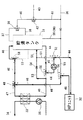
次に、この発明の第1実施形態について図1に基づき説明する。
1は湯水を貯湯する貯湯タンク、2は貯湯タンク1内の湯水を加熱するヒートポンプ式加熱手段、3は貯湯タンク1内の湯水を用いて2次側の暖房用循環水を加熱するための暖房用熱交換器、4は床暖房パネル等の暖房負荷(図示せず)に暖房用循環水が循環可能に接続された暖房用熱交換器3の2次側の2次側暖房循環回路、5は2次側暖房循環回路4に設けられた2次側暖房循環ポンプである。
Next, a first embodiment of the present invention will be described with reference to FIG.
1 is a hot water storage tank for storing hot water, 2 is a heat pump heating means for heating the hot water in the hot water storage tank 1, and 3 is heating for heating the circulating water for heating on the secondary side using the hot water in the hot water storage tank 1. 4 is a secondary side heating circulation circuit on the secondary side of the heating heat exchanger 3 in which the circulating water for heating is connected to a heating load (not shown) such as a floor heating panel. Is a secondary side heating circulation pump provided in the secondary side heating circulation circuit 4.

6は貯湯タンク1の底部へ市水を供給する入水管、7は貯湯タンク1の上部から湯水を出湯する出湯管、8は貯湯タンク1の中間部から湯水を出湯する中間出湯管、9は出湯管7と中間出湯管8の湯水を適温に混合する中間混合弁、10は中間混合弁9からの湯水を給湯する中間給湯管、11は入水管6から分岐された給水管、12は中間給湯管10からの湯水と給水管11からの市水を設定温度に混合する給湯混合弁、13は給湯混合弁12からの湯水を給湯する給湯管である。   6 is a water inlet pipe for supplying city water to the bottom of the hot water storage tank 1, 7 is a hot water outlet pipe for discharging hot water from the upper part of the hot water storage tank 1, 8 is an intermediate hot water outlet pipe for discharging hot water from the intermediate part of the hot water storage tank 1, 9 An intermediate mixing valve 10 for mixing hot water from the hot water outlet pipe 7 and the intermediate hot water pipe 8 at an appropriate temperature, 10 is an intermediate hot water pipe for supplying hot water from the intermediate mixing valve 9, 11 is a water supply pipe branched from the incoming water pipe 6, and 12 is an intermediate A hot water supply mixing valve 13 for mixing hot water from the hot water supply pipe 10 and city water from the water supply pipe 11 to a set temperature, and 13 is a hot water supply pipe for supplying hot water from the hot water mixing valve 12.

14は貯湯タンク1の下部とヒートポンプ式加熱手段2の入口とを接続する第1管路、15は第1管路14途中に設けられ貯湯タンク1の下部の湯水をヒートポンプ式加熱手段2へ流通させる循環ポンプ、16はヒートポンプ式加熱手段2の出口と貯湯タンク1の上部とを接続する第2管路、17は第2管路16途中と第1管路14の循環ポンプ15より貯湯タンク1側とを接続する第3管路、18は第3管路17と第1管路14との接続点に設けられた第1三方弁である。前記第1三方弁18は循環ポンプ15の吸入側のcポートを第3管路17側のaポートか第1管路の貯湯タンク1側のbポートの何れか一方に選択的に接続する構成としている。   Reference numeral 14 denotes a first pipe connecting the lower part of the hot water storage tank 1 and the inlet of the heat pump type heating means 2, and 15 denotes a first pipe provided in the middle of the first pipe 14 to distribute hot water from the lower part of the hot water storage tank 1 to the heat pump type heating means 2. The circulation pump 16 is a second pipe connecting the outlet of the heat pump type heating means 2 and the upper part of the hot water storage tank 1, and 17 is the hot water storage tank 1 from the circulation pump 15 in the middle of the second pipe 16 and the first pipe 14. Reference numeral 18 denotes a first three-way valve provided at a connection point between the third pipeline 17 and the first pipeline 14. The first three-way valve 18 selectively connects the c port on the suction side of the circulation pump 15 to either the a port on the third conduit 17 side or the b port on the hot water storage tank 1 side of the first conduit. It is said.

19は第1管路14の循環ポンプ15よりヒートポンプ式加熱手段2側と暖房用熱交換器3の入口とを接続する第4管路、20は第1管路14と第4管路19との接続点に設けられた第2三方弁である。前記第2三方弁20は循環ポンプ16の吐出側のcポートを第1管路14のヒートポンプ式加熱手段2側のaポートか第4管路19側のbポートの何れか一方を選択的に接続する構成としている。   19 is a fourth pipe connecting the heat pump type heating means 2 side and the inlet of the heat exchanger 3 for heating from the circulation pump 15 of the first pipe 14, and 20 is a first pipe 14 and a fourth pipe 19. It is the 2nd three-way valve provided in the connection point. The second three-way valve 20 selectively selects the c-port on the discharge side of the circulation pump 16 as either the a-port on the heat pump heating means 2 side of the first conduit 14 or the b-port on the fourth conduit 19 side. It is configured to connect.

21は暖房用熱交換器3の出口と貯湯タンク1の下部(あるいは中間部)とを接続する第5管路、22は第2管路16途中の第3管路17との接続点よりも貯湯タンク1側と第4管路19途中とを接続する第6管路、23は第2管路16と第6管路22との接続点に設けられた第3三方弁、24は第4管路19と第6管路22との接続点に設けられた第4三方弁である。前記第3三方弁23は第6管路22側のaポートか第2管路16の貯湯タンク1側のbポートの何れか一方を第2管路16のヒートポンプ式加熱手段2側のcポートに選択的に接続可能とする構成とし、好ましくはcポートからの温水をaポートとbポートに任意に調節される比率でその流量を分配できる構成の分配弁とすることが望ましい。前記第4三方弁24は第4管路19の暖房用熱交換器3側のaポートか第6管路22側のbポートの何れか一方を第4管路19の貯湯タンク1側のcポートに選択的に接続可能とする構成とし、好ましくはaポートとbポートとが連通して温水が流通可能にする構成が望ましい。   21 is a fifth pipe connecting the outlet of the heat exchanger 3 for heating and the lower part (or middle part) of the hot water storage tank 1, and 22 is a connection point with the third pipe 17 in the middle of the second pipe 16. A sixth pipe connecting the hot water storage tank 1 side and the middle of the fourth pipe 19, 23 is a third three-way valve provided at a connection point between the second pipe 16 and the sixth pipe 22, and 24 is a fourth This is a fourth three-way valve provided at the connection point between the pipe line 19 and the sixth pipe line 22. The third three-way valve 23 is either a port on the sixth pipeline 22 side or b port on the hot water storage tank 1 side of the second pipeline 16 or c port on the heat pump heating means 2 side of the second pipeline 16. It is desirable that the distribution valve be configured to be capable of selectively connecting the flow rate of hot water from the c port to the a port and the b port. The fourth three-way valve 24 is configured such that either the a port on the heating heat exchanger 3 side of the fourth pipe line 19 or the b port on the sixth pipe line 22 side is c on the hot water storage tank 1 side of the fourth pipe line 19. A configuration that allows selective connection to the port, and preferably a configuration that allows the a port and the b port to communicate with each other so that hot water can be circulated is desirable.

25は第5管路21途中から第1管路14の第2三方弁20よりヒートポンプ式加熱手段2側とを接続する第7管路、26は第5管路21と第7管路25との接続点に設けられた第5三方弁である。前記第5三方弁26は第5管路21の暖房用熱交換器3側のcポートを第5管路21の貯湯タンク1側のaポートか第7管路25側のbポートの何れか一方に選択的に接続する構成としている。   25 is a seventh pipe connecting the heat pump type heating means 2 side from the second three-way valve 20 of the first pipe 14 from the middle of the fifth pipe 21, and 26 is a fifth pipe 21 and a seventh pipe 25. It is the 5th three-way valve provided in the connection point. In the fifth three-way valve 26, the c port on the heating heat exchanger 3 side of the fifth pipe 21 is either the a port on the hot water storage tank 1 side of the fifth pipe 21 or the b port on the seventh pipe 25 side. It is configured to selectively connect to one.

27は第2管路16の第3管路17との接続点よりもヒートポンプ式加熱手段2側から分岐され貯湯タンク1の下部(あるいは中間部)に接続される第8管路、28は第2管路16と第8管路27との接続点に設けられた第6三方弁である。前記第6三方弁28は第2管路16のヒートポンプ式加熱手段2側のcポートを第8管路27側のaポートか第2管路16の貯湯タンク1側のbポートの何れか一方に選択的に接続する構成としている。   Reference numeral 27 denotes an eighth pipe that branches from the side of the heat pump heating means 2 than the connection point of the second pipe 16 to the third pipe 17 and is connected to the lower part (or the middle part) of the hot water storage tank 1, and 28 is the second one. This is a sixth three-way valve provided at a connection point between the two pipelines 16 and the eighth pipeline 27. In the sixth three-way valve 28, the c port on the heat pump type heating means 2 side of the second pipe line 16 is either the a port on the eighth pipe line 27 side or the b port on the hot water storage tank 1 side of the second pipe line 16. It is set as the structure selectively connected to.

29は第2管路16の第3三方弁23よりも貯湯タンク1側から分岐され貯湯タンク1の中間部に接続される第9管路、30は第2管路16と第9管路29との接続点に設けられた第7三方弁である。前記第7三方弁30は第2管路16のヒートポンプ式加熱手段2側のcポートを第2管路16の貯湯タンク1側のaポートか第9管路29側のbポートの何れか一方に選択的に接続する構成としている。   Reference numeral 29 is a ninth pipe branched from the hot water storage tank 1 side of the second three-way valve 23 from the third three-way valve 23 and connected to an intermediate portion of the hot water storage tank 1, and reference numeral 30 is the second pipe 16 and the ninth pipe 29. Is a seventh three-way valve provided at the connection point. In the seventh three-way valve 30, the c port on the heat pump heating means 2 side of the second pipe line 16 is either the a port on the hot water storage tank 1 side of the second pipe line 16 or the b port on the ninth pipe line 29 side. It is set as the structure selectively connected to.

ここで、前記ヒートポンプ式加熱手段2について詳述すると、圧縮機(図示せず)、貯湯タンク1内の温水を加熱するガスクーラとしての水冷媒熱交換器(図示せず)、減圧器(図示せず)、蒸発器としての空気熱交換器(図示せず)が環状に接続され、冷媒として二酸化炭素が封入され、高圧側で超臨界状態となる超臨界蒸気圧縮ヒートポンプサイクルを形成しているものである。   Here, the heat pump heating means 2 will be described in detail. A compressor (not shown), a water refrigerant heat exchanger (not shown) as a gas cooler for heating hot water in the hot water storage tank 1, and a decompressor (not shown). 1), an air heat exchanger (not shown) as an evaporator is connected in a ring shape, carbon dioxide is enclosed as a refrigerant, and forms a supercritical vapor compression heat pump cycle that becomes a supercritical state on the high pressure side It is.

次に、この第1実施形態の作動について説明する。
図2はヒートポンプ式加熱手段2の起動時(HP立上げ運転)の作動を説明する図であり、第1三方弁18をbポートとcポートが連通するようにし、第2三方弁20をcポートとaポートが連通するようにし、第6三方弁28をcポートとaポートが連通するようにすると共に、ヒートポンプ式加熱手段2と循環ポンプ15を駆動して、貯湯タンク1の底部から取り出した湯水を第1管路14と第2管路16と第8管路27を介して循環加熱して貯湯タンク1の中間部へ戻す。このHP立上げ運転時においては、ヒートポンプ式加熱手段2の圧縮機を起動してからヒートポンプサイクルが安定してヒートポンプ式加熱手段2から出る実際に沸き上げた温水の温度が所望の温度まで上昇するのに5〜10分程度の時間を要するが、その間に沸き上げた中途半端な温度の温水は貯湯タンク1の下部(あるいは中間部)に戻される。このようにすることで貯湯タンク1内の上部に中途半端な温度の温水を供給することがない。
Next, the operation of the first embodiment will be described.
FIG. 2 is a diagram for explaining the operation of the heat pump type heating means 2 at the time of start-up (HP start-up operation). The port and the a port communicate with each other, and the sixth three-way valve 28 communicates with the c port and the a port, and the heat pump heating means 2 and the circulation pump 15 are driven to take out from the bottom of the hot water tank 1 The hot and cold water is circulated and heated through the first pipe line 14, the second pipe line 16, and the eighth pipe line 27 and returned to the intermediate portion of the hot water storage tank 1. In this HP startup operation, the heat pump cycle is stabilized after starting the compressor of the heat pump type heating means 2, and the temperature of the hot water actually boiled from the heat pump type heating means 2 rises to a desired temperature. However, it takes about 5 to 10 minutes, but the hot water boiled in the meantime is returned to the lower part (or middle part) of the hot water storage tank 1. By doing in this way, the hot water of a halfway temperature is not supplied to the upper part in the hot water storage tank 1.

なお、このとき、当該運転に関係のない温水が循環してしまうことを防止するために、その運転に関連しない三方弁を適切な位置に設定しておくことが望ましく、ここでは、第5三方弁26をbポートとcポートが連通するようにし、第4三方弁24をaポートとcポートが連通するようにすることで、貯湯タンク1内の温水の温度成層状態を余計に乱してしまうことを防止することが可能となる。   At this time, in order to prevent the hot water unrelated to the operation from circulating, it is desirable to set the three-way valve not related to the operation to an appropriate position. By making the valve 26 communicate with the port b and the port c, and the fourth three-way valve 24 with the port a and the port c, the temperature stratification of the hot water in the hot water storage tank 1 is further disturbed. Can be prevented.

そして沸き上げた温水の温度が所望の温度になると、HP立上げ運転を終了し、図3に示す貯湯運転を行う。この貯湯運転では、HP立上げ運転状態から第6三方弁28をcポートとbポートが連通するようにし、第3三方弁23をcポートとbポートが連通するようにし、第7三方弁30をcポートとaポートが連通するようにする。そして、循環ポンプ15の作動により貯湯タンク1下部の低温水がヒートポンプ式加熱手段2によって所望の高温まで沸き上げられ、高温水は貯湯タンク1の上部から積層状に順次貯湯されていく。   When the temperature of the heated hot water reaches a desired temperature, the HP startup operation is terminated, and the hot water storage operation shown in FIG. 3 is performed. In this hot water storage operation, from the HP start-up operation state, the sixth three-way valve 28 is communicated with the c port and the b port, the third three way valve 23 is communicated with the c port and the b port, and the seventh three-way valve 30 The c port and the a port communicate with each other. Then, the low-temperature water in the lower part of the hot water storage tank 1 is boiled up to a desired high temperature by the heat pump type heating means 2 by the operation of the circulation pump 15, and the hot water is sequentially stored in a stacked form from the upper part of the hot water storage tank 1.

この貯湯運転は、電力会社によって設定された電気料金単価が安価な深夜時間帯(例、深夜23時から翌朝7時まで)に行われ、翌日に必要な給湯熱量+暖房熱量を沸き上げようとするものである。ここで給湯熱量および暖房熱量は過去数日間の学習制御等により決定される。   This hot water storage operation is performed in the late-night hours (eg, from 23:00 to 7:00 the next morning) when the electricity unit price set by the electric power company is low, and tries to boil the required hot water supply heat amount + heating heat amount the next day To do. Here, the hot water supply heat amount and the heating heat amount are determined by learning control or the like in the past several days.

そして、給湯を行う際は図4に示すように、給湯管13の端部の蛇口(図示せず)が開放されると、入水管6から市水が貯湯タンク1の下部に流入し、出湯管7から高温水が出湯され、中間混合弁9を介して中間給湯管10を流通し、給湯混合弁12にて給水管11からの市水と混合されて設定温度に調節されて、給湯管13を介して蛇口から流出する。ここで、貯湯タンク1の中間部に中温水が多量に貯湯されている状況であれば、前記中間混合弁9を用いて中温水と高温水を混合させる、あるいは中温水をそのまま出湯させる等して中温水を優先的に出湯することが望ましい。   When hot water is supplied, as shown in FIG. 4, when a faucet (not shown) at the end of the hot water supply pipe 13 is opened, city water flows into the lower part of the hot water storage tank 1 from the water intake pipe 6. Hot water is discharged from the pipe 7, flows through the intermediate hot water supply pipe 10 through the intermediate mixing valve 9, is mixed with city water from the hot water supply pipe 11 by the hot water supply mixing valve 12, and is adjusted to the set temperature. Out of the faucet through 13. Here, if there is a large amount of hot water stored in the intermediate portion of the hot water storage tank 1, the hot water and hot water are mixed using the intermediate mixing valve 9 or the hot water is discharged as it is. It is desirable to preferentially discharge hot water.

次に、暖房運転を行う場合を説明する。図5は深夜時間帯に沸き上げられた貯湯タンク1内の高温水を用いて暖房を行う蓄暖運転を説明する図であり、第7三方弁30をaポートとcポートが連通するようにし、第3三方弁23をbポートとcポートが連通するようにし、第1三方弁18をaポートとcポートが連通するようにし、第2三方弁20をcポートとbポートが連通するようにし、第4三方弁24をcポートとaポートが連通するようにし、第5三方弁26をcポートとaポートが連通するようにすると共に、循環ポンプ15を駆動して、貯湯タンク1の上部の高温水を第2管路16、第3管路17、第1管路14、循環ポンプ15、第4管路19、暖房用熱交換器3、第5管路21の順で流通させて貯湯タンク1の下部(あるいは中間部)へ戻し、暖房用熱交換器3の2次側の2次側暖房循環回路4へ熱を供給することで蓄暖運転を行う。   Next, a case where the heating operation is performed will be described. FIG. 5 is a diagram for explaining a heat storage operation in which heating is performed using high-temperature water in the hot water storage tank 1 boiled in the midnight time zone. The seventh three-way valve 30 is connected to the a port and the c port. The b port and c port communicate with the third three-way valve 23, the a port and c port communicate with the first three-way valve 18, and the c port and b port communicate with the second three-way valve 20. The fourth three-way valve 24 communicates with the c port and the a port, the fifth three-way valve 26 communicates with the c port and the a port, and the circulation pump 15 is driven to drive the hot water storage tank 1 The upper high-temperature water is circulated in the order of the second pipe 16, the third pipe 17, the first pipe 14, the circulation pump 15, the fourth pipe 19, the heating heat exchanger 3, and the fifth pipe 21. Return to the lower part (or middle part) of the hot water storage tank 1 and the heat exchanger 3 for heating. Performing 蓄暖 operation by supplying heat to the secondary side heater circulation circuit 4 follows side.

なお、このとき、当該運転に関係のない温水が循環してしまうことを防止するために、その運転に関連しない三方弁を適切な位置に設定しておくことが望ましく、ここでは、第6三方弁28をcポートとaポートが連通するようにすることで、貯湯タンク1内の温水の温度成層状態を余計に乱してしまうことを防止することが可能となる。   At this time, in order to prevent circulating hot water not related to the operation, it is desirable to set a three-way valve not related to the operation to an appropriate position. By making the valve 28 communicate with the c port and the a port, it is possible to prevent the temperature stratification of the hot water in the hot water storage tank 1 from being disturbed excessively.

そして貯湯タンク1の側面に多数設けられた貯湯温度センサ(図示せず)によって検出される貯湯タンク1内の蓄熱量が所定値よりも少なくなると、ヒートポンプ式加熱手段2を起動して沸き上げた高温水を利用して暖房を行うようにしている。その際に、ヒートポンプ式加熱手段2の起動に時間がかかるため、ヒートポンプサイクルが立上がるまでの間は図6に示す蓄暖運転+HP立上げ運転を行う。前記の蓄暖運転の状態から、第5三方弁26をcポートとbポートが連通するようにし、第6三方弁28をcポートとaポートが連通するようにすると共に、ヒートポンプ式加熱手段2を起動する。   When the amount of stored heat in the hot water storage tank 1 detected by hot water storage temperature sensors (not shown) provided on the side surface of the hot water storage tank 1 is less than a predetermined value, the heat pump heating means 2 is activated to boil up. Heating is performed using hot water. At that time, since it takes time to start up the heat pump heating means 2, the warm-up operation + HP start-up operation shown in FIG. 6 is performed until the heat pump cycle starts up. From the state of the heat storage operation, the fifth three-way valve 26 communicates with the c port and the b port, the sixth three-way valve 28 communicates with the c port and the a port, and the heat pump heating means 2 Start up.

これにより、貯湯タンク1の上部の高温水は第2管路16、第3管路17、第1管路14、循環ポンプ15、第4管路19、暖房用熱交換器3、第5管路21、第7管路25、第2管路16、第8管路27の順で流通して貯湯タンク1の下部(あるいは中間部)へ戻され、暖房用熱交換器3で放熱した後の温水がヒートポンプ式加熱手段2に流入されて沸き上げられるため、ヒートポンプ式加熱手段2の入水温度が低くなってヒートポンプサイクルの高圧異常を引き起こすことなく、蓄暖運転とHP立上げ運転が同時に効率よく行うことが可能となる。   Thereby, the high-temperature water in the upper part of the hot water storage tank 1 is supplied from the second pipe 16, the third pipe 17, the first pipe 14, the circulation pump 15, the fourth pipe 19, the heating heat exchanger 3, and the fifth pipe. After flowing in the order of the passage 21, the seventh conduit 25, the second conduit 16, and the eighth conduit 27, the heat is returned to the lower part (or the middle part) of the hot water storage tank 1 and radiated by the heat exchanger 3 for heating. Since the warm water of the heat pump flows into the heat pump heating means 2 and is boiled up, the heat storage operation and the HP start-up operation are efficient at the same time without lowering the incoming water temperature of the heat pump heating means 2 and causing a high pressure abnormality in the heat pump cycle. It can be done well.

そして、ヒートポンプ式加熱手段2で沸き上げた温水の温度が所定の温度以上に達すると蓄暖運転+HP立上げ運転を終了し、図7に示すようにヒートポンプ式加熱手段2で沸き上げた高温水を直接暖房用熱交換器3へ流通させつつ貯湯運転を行う直暖運転+貯湯運転を行う。   Then, when the temperature of the hot water boiled by the heat pump heating means 2 reaches a predetermined temperature or more, the warm-up operation + HP start-up operation is terminated, and the hot water boiled by the heat pump heating means 2 as shown in FIG. Is directly distributed to the heat exchanger 3 for heating, and a direct warming operation and a hot water storage operation are performed in which the hot water storage operation is performed.

この図7に示す直暖運転+貯湯運転では、先の蓄暖運転+HP立上げ運転の状態から、第1三方弁18をbポートとcポートが連通するようにし、第2三方弁20をcポートとaポートが連通するようにし、第6三方弁28をcポートとbポートが連通するようにし、第3三方弁23をaポート側50%bポート側50%となるように調節し、第4三方弁24をbポートとaポートが連通するようにし、第5三方弁26をcポートとaポートが連通するようにして、貯湯タンク1下部の低温水を第1管路14、循環ポンプ15を流通してヒートポンプ式加熱手段2において所定の高温に沸き上げ、第2管路16、第6管路22、第4管路19、暖房用熱交換器3、第5管路21の順で直接暖房用熱源として用いた後に貯湯タンク1の下部(あるいは中間部)に戻す一方で、ヒートポンプ式加熱手段2において所定の高温に沸き上げられた高温水は、前記第3三方弁23によってその一部が分流して第2管路16を貯湯タンク1の上部へ向かって流通し、貯湯タンク1の上部から積層状に貯湯される。   In the direct warming operation + hot water storage operation shown in FIG. 7, from the state of the previous warming operation + HP start-up operation, the first three-way valve 18 is connected to the b port and the c port, and the second three-way valve 20 is connected to the c port. The port and the a port communicate with each other, the sixth three-way valve 28 communicates with the c port and the b port, and the third three-way valve 23 is adjusted so that the a port side is 50% and the b port side is 50%. The fourth three-way valve 24 is connected to the b port and the a port, and the fifth three-way valve 26 is connected to the c port and the a port so that the low temperature water in the lower part of the hot water storage tank 1 is circulated in the first pipe 14. It circulates through the pump 15 and is heated to a predetermined high temperature in the heat pump type heating means 2, and the second pipe line 16, the sixth pipe line 22, the fourth pipe line 19, the heating heat exchanger 3, and the fifth pipe line 21. After using it directly as a heat source for heating, On the other hand, the high-temperature water boiled to a predetermined high temperature in the heat pump heating means 2 is partly diverted by the third three-way valve 23 and the second pipe 16 is connected to the hot water storage tank. 1 circulates toward the top of the hot water 1 and is stored in a stacked form from the top of the hot water storage tank 1.

ここで、前記第3三方弁23はaポート側の流量とbポート側の流量の比率を調整できる分配弁としており、貯湯タンク1内の残熱量と暖房負荷の状態に応じてヒートポンプ式加熱手段2において沸き上げた高温水の分配の割合を変更可能とし、例えば、暖房負荷が比較的小さく、かつ残湯量が少ない場合には、第3三方弁23のbポート側の流量比率を大きくしてヒートポンプ式加熱手段2は定格能力で稼働しつつ、暖房出力は小さくして貯湯する熱量を多くすることができ、効率のよい運転が可能となる。   Here, the third three-way valve 23 is a distribution valve capable of adjusting the ratio of the flow rate on the a port side and the flow rate on the b port side, and heat pump heating means according to the amount of residual heat in the hot water storage tank 1 and the state of the heating load. For example, when the heating load is relatively small and the amount of remaining hot water is small, the flow rate ratio on the b port side of the third three-way valve 23 is increased. While the heat pump type heating means 2 operates at the rated capacity, the heating output can be reduced to increase the amount of heat to be stored, and efficient operation is possible.

また、貯湯タンク1内の残湯量が最低量(給湯に必要な分)は確保されているものの暖房用としては貯湯タンク31内に熱量が確保されておらず、かつ暖房負荷が大きい場合には、図8に示すように直暖運転のみを行う。ここでは第3三方弁23のbポートを全閉、aポートを全開とし、ヒートポンプ式加熱手段2で沸き上げた高温水が全て暖房用熱交換器3へ流通するようにしている。もし、暖房負荷が減少し、ヒートポンプ式加熱手段2の定格能力よりも下回った場合は、第3三方弁23のbポート側を開き、図7に示したように直暖運転+貯湯運転を行うようにすると効率のよい運転が行える。   In addition, when the remaining amount of hot water in the hot water storage tank 1 is secured (the amount necessary for hot water supply), the amount of heat is not secured in the hot water storage tank 31 for heating, and the heating load is large. As shown in FIG. 8, only the direct warming operation is performed. Here, the b port of the third three-way valve 23 is fully closed and the a port is fully opened, so that all of the high-temperature water boiled by the heat pump heating means 2 flows to the heating heat exchanger 3. If the heating load decreases and falls below the rated capacity of the heat pump type heating means 2, the b port side of the third three-way valve 23 is opened, and direct heating operation + hot water storage operation is performed as shown in FIG. By doing so, efficient operation can be performed.

またここで、ヒートポンプ式加熱手段2は外気と熱交換可能に配置されるため、ヒートポンプ式加熱手段2への湯水の循環回路は凍結する恐れがある。そのため、図5に示した蓄暖運転においては、定期的に一定時間だけ図9に示す蓄暖運転+HP凍結予防運転を行うようにしている。この蓄暖運転+HP凍結予防運転について説明すると、図5の蓄暖運転の状態から、第5三方弁26をcポートとbポートが連通するようにし、第6三方弁28をcポートとaポートが連通するようにし、暖房用熱交換器3で暖房に供されて温度低下した温水が第5管路21、第7管路25、第1管路14を流通してヒートポンプ式加熱手段2へ流入し、第2管路16、第8管路27を流通して貯湯タンク1の下部(あるいは中間部)へ戻されることによってヒートポンプ式加熱手段2およびそこへ至るまでの管路の凍結予防運転が行われる。このように、暖房用熱交換器3で熱交換して温度低下した温水を用いてヒートポンプ式加熱手段2の凍結予防を行えるため、蓄暖運転を停止することなく、また暖房熱交換器3への供給残熱量によってHP凍結予防運転が行えると共に、貯湯タンク1へ戻す温水の温度が低下し、次回の貯湯運転においてヒートポンプ式加熱手段2への供給水温を抑制できるため、沸き上げ効率も向上するものである。   Here, since the heat pump type heating means 2 is arranged so as to be able to exchange heat with the outside air, the hot water circulation circuit to the heat pump type heating means 2 may be frozen. Therefore, in the warm-up operation shown in FIG. 5, the warm-up operation + HP freeze prevention operation shown in FIG. 9 is periodically performed for a fixed time. The warm storage operation + HP freeze prevention operation will be described. From the state of the warm storage operation shown in FIG. 5, the fifth three-way valve 26 is connected to the c port and the b port, and the sixth three way valve 28 is connected to the c port and the a port. , The hot water which has been subjected to heating in the heating heat exchanger 3 and reduced in temperature flows through the fifth pipe 21, the seventh pipe 25 and the first pipe 14 to the heat pump heating means 2. The heat pump heating means 2 and the pipe freezing prevention operation up to the heat pump type heating means 2 by flowing in, flowing through the second pipe line 16 and the eighth pipe line 27 and returning to the lower part (or intermediate part) of the hot water storage tank 1 Is done. Thus, since the heat pump type heating means 2 can be prevented from freezing using the hot water whose temperature has been reduced by exchanging heat in the heating heat exchanger 3, it is possible to return to the heating heat exchanger 3 without stopping the heat storage operation. HP freezing prevention operation can be performed by the amount of residual heat supplied, and the temperature of the hot water returned to the hot water storage tank 1 is lowered, and the temperature of the supplied water to the heat pump heating means 2 can be suppressed in the next hot water storage operation, so that the boiling efficiency is improved. Is.

また、蓄暖運転あるいは直暖運転を行っていないときのHP凍結予防運転について、図10を基に説明すると、図2に示した前記HP立上げ運転と同様の配管経路をたどり、ヒートポンプ式加熱手段2を起動しない状態で貯湯タンク1下部の湯水をヒートポンプ式加熱手段2へ循環させて貯湯タンク1の下部(あるいは中間部)へ戻すようにして定期的に一定時間だけヒートポンプ式加熱手段2の凍結予防を行っている。   Further, the HP freeze prevention operation when the warming-up operation or the direct warming operation is not performed will be described with reference to FIG. 10. The same piping path as the HP start-up operation shown in FIG. The hot water in the lower part of the hot water storage tank 1 is circulated to the heat pump type heating means 2 and returned to the lower part (or the intermediate part) of the hot water storage tank 1 without starting the means 2 so that the heat pump type heating means 2 is regularly operated for a certain time. Freezing prevention is performed.

さらに、HP凍結予防運転としては、図11に示すように、貯湯タンク1内部の中温水を用いて行うことも可能である。第7三方弁30をbポートとcポートが連通するようにし、第1三方弁18をaポートとcポートが連通するようにし、第2三方弁20をcポートとaポートが連通するようにし、第6三方弁28をcポートとaポートが連通するようにし、貯湯タンク1の中間部に貯まっている中温水を、第9管路29、第2管路16、第3管路17、第1管路14、循環ポンプ15、ヒートポンプ式加熱手段2、第2管路16、第8管路27、貯湯タンク1の下部(あるいは中間部)の順で流通させ、ヒートポンプ式加熱手段2の凍結予防を行うことができると共に、貯湯タンク1内の中温水が温度低下して貯湯タンク1内に戻るため、ヒートポンプ式加熱手段2での加熱効率の悪い中温水を有効利用して貯湯運転時の加熱効率も向上することができるものである。   Furthermore, as shown in FIG. 11, the HP freeze prevention operation can be performed using medium temperature water in the hot water storage tank 1. The b port and c port are in communication with the seventh three-way valve 30, the a port and c port are in communication with the first three-way valve 18, and the c port and a port are in communication with the second three-way valve 20. The sixth three-way valve 28 communicates with the c port and the a port, and the medium temperature water stored in the intermediate portion of the hot water storage tank 1 is supplied to the ninth pipe line 29, the second pipe line 16, the third pipe line 17, The first pipe 14, the circulation pump 15, the heat pump heating means 2, the second pipe 16, the eighth pipe 27, and the lower part (or middle part) of the hot water storage tank 1 are circulated in this order. While freezing prevention can be performed, the temperature of the medium temperature water in the hot water storage tank 1 is lowered and returned to the hot water storage tank 1, so that the hot water with poor heating efficiency in the heat pump heating means 2 is effectively used during hot water storage operation. The heating efficiency of can also be improved It is.

なお、このとき、当該運転に関係のない温水が循環してしまうことを防止するために、その運転に関連しない三方弁を適切な位置に設定しておくことが望ましく、ここでは、第5三方弁26をcポートとaポートが連通するようにすることで、貯湯タンク1内の温水の温度成層状態を余計に乱してしまうことを防止することが可能となる。   At this time, in order to prevent the hot water unrelated to the operation from circulating, it is desirable to set the three-way valve not related to the operation to an appropriate position. By making the valve 26 communicate with the c port and the a port, it becomes possible to prevent the temperature stratification of the hot water in the hot water storage tank 1 from being disturbed excessively.

このように、本発明の第1実施形態によれば、ヒートポンプ式加熱手段2へ貯湯タンク1内の湯水を循環させる循環ポンプ15と、暖房用熱交換器3へ貯湯タンク1内の湯水を循環させる循環ポンプ15を1台で兼用して貯湯運転、蓄暖運転、直暖運転等各種運転を行うことが可能となったと共に、貯湯タンク1内の高温水を用いて暖房を行う蓄暖運転からヒートポンプ式加熱手段2で沸き上げた高温水を直接暖房用熱交換器3へ流通させる直暖運転への切り換え時において、一旦暖房を停止することなくHP立上げ運転を行うことができ、さらに、蓄暖運転中において暖房用熱交換器3で放熱した温水をヒートポンプ式加熱手段2へ循環させることができるので、蓄暖運転を行いながら湯水の循環によるヒートポンプ式加熱手段2の凍結予防運転を効率よく行うことができるものである。   As described above, according to the first embodiment of the present invention, the circulation pump 15 that circulates the hot water in the hot water storage tank 1 to the heat pump heating means 2 and the hot water in the hot water storage tank 1 to the heat exchanger 3 for heating are circulated. It is possible to perform various operations such as a hot water storage operation, a warm storage operation, and a direct warm operation by using one circulating pump 15 to be used, and a warm storage operation that performs heating using high-temperature water in the hot water storage tank 1 When switching to the direct warming operation in which the high-temperature water boiled by the heat pump heating means 2 is directly circulated to the heat exchanger 3 for heating, the HP start-up operation can be performed without stopping the heating. Since the hot water radiated by the heating heat exchanger 3 during the heat storage operation can be circulated to the heat pump type heating means 2, the freezing of the heat pump type heating means 2 by circulating hot water while performing the heat storage operation can be performed. It is capable of performing efficient operation.

次に、本発明の第2実施形態について図12に基づき説明する。なお、先の第1実施形態と構成および作動がほとんど同一のものについては一部説明を省略した。
31は湯水を貯湯する貯湯タンク、32は貯湯タンク1内の湯水を加熱するヒートポンプ式加熱手段、33は貯湯タンク1内の湯水を用いて2次側の暖房用循環水を加熱するための暖房用熱交換器、34は床暖房パネル等の暖房負荷(図示せず)に暖房用循環水が循環可能に接続された暖房用熱交換器33の2次側の2次側暖房循環回路、35は2次側暖房循環回路4に設けられた2次側暖房循環ポンプである。
Next, a second embodiment of the present invention will be described with reference to FIG. A part of the configuration and operation that are almost the same as those of the first embodiment are partially omitted.
31 is a hot water storage tank for storing hot water, 32 is a heat pump heating means for heating the hot water in the hot water storage tank 1, and 33 is heating for heating the circulating water for heating on the secondary side using the hot water in the hot water storage tank 1. A heat exchanger for heat 34, a secondary side heating circulation circuit for the secondary side of the heat exchanger 33 for heating, in which the circulating water for heating is connected to a heating load (not shown) such as a floor heating panel, 35 Is a secondary side heating circulation pump provided in the secondary side heating circulation circuit 4.

36は貯湯タンク31の底部へ市水を供給する入水管、37は貯湯タンク31の上部から湯水を出湯する出湯管、38は貯湯タンク31の中間部から湯水を出湯する中間出湯管、39は出湯管37と中間出湯管38の湯水を適温に混合する中間混合弁、40は中間混合弁39からの湯水を給湯する中間給湯管、41は入水管36から分岐された給水管、42は中間給湯管40からの湯水と給水管41からの市水を設定温度に混合する給湯混合弁、43は給湯混合弁42からの湯水を給湯する給湯管である。   36 is a water intake pipe for supplying city water to the bottom of the hot water storage tank 31, 37 is a hot water discharge pipe for discharging hot water from the upper part of the hot water storage tank 31, 38 is an intermediate hot water discharge pipe for discharging hot water from the intermediate part of the hot water storage tank 31, and 39 is An intermediate mixing valve that mixes hot water from the hot water outlet pipe 37 and the intermediate hot water outlet pipe 38 at an appropriate temperature, 40 is an intermediate hot water pipe that supplies hot water from the intermediate mixing valve 39, 41 is a water supply pipe branched from the water inlet pipe 36, and 42 is intermediate A hot water supply mixing valve 43 for mixing hot water from the hot water supply pipe 40 and city water from the water supply pipe 41 to a set temperature, and 43 is a hot water supply pipe for supplying hot water from the hot water mixing valve 42.

44は貯湯タンク31の下部とヒートポンプ式加熱手段32の入口とを接続する第11管路、45は第11管路44途中に設けられ、貯湯タンク31下部の湯水をヒートポンプ式加熱手段42へ流通させる循環ポンプ、46はヒートポンプ式加熱手段42の出口と貯湯タンク32の上部とを接続する第12管路、47は第12管路46途中と暖房用熱交換器33の入口とを接続する第13管路、48は第12管路46と第13管路47との接続点に設けられた第11三方弁である。前記第11三方弁48は第13管路47側のaポートか第12管路46の貯湯タンク31側のbポートの何れか一方を第12管路46のヒートポンプ式加熱手段32側のcポートに選択的に接続可能とする構成とし、好ましくはcポートからの温水をaポートとbポートに任意に調節される比率でその流量を分配できる構成の分配弁とすることが望ましい。   44 is an eleventh pipe connecting the lower part of the hot water storage tank 31 and the inlet of the heat pump type heating means 32, 45 is provided in the middle of the eleventh pipe 44, and the hot water in the lower part of the hot water storage tank 31 is circulated to the heat pump type heating means 42. A circulation pump 46 for connecting the outlet of the heat pump type heating means 42 and the upper part of the hot water storage tank 32, and 47 for connecting the middle of the twelfth pipe 46 and the inlet of the heat exchanger 33 for heating. Reference numerals 13 and 48 denote an eleventh three-way valve provided at a connection point between the twelfth pipe 46 and the thirteenth pipe 47. The eleventh three-way valve 48 is either an a port on the thirteenth conduit 47 side or a b port on the hot water storage tank 31 side of the twelfth conduit 46, or a c port on the heat pump heating means 32 side of the twelfth conduit 46. It is desirable that the distribution valve be configured to be capable of selectively connecting the flow rate of hot water from the c port to the a port and the b port.

49は暖房用熱交換器33の出口と第11管路44の循環ポンプ45よりも貯湯タンク31側とを接続する第14管路、50は第14管路49と第11管路44との接続点に設けられた第12三方弁である。前記第12三方弁50は第14管路49側のaポートか第11管路44の貯湯タンク31側のbポートの何れか一方を第11管路44の循環ポンプ45の吸入側のcポートに選択的に接続可能とする構成としている。   49 is a fourteenth pipe connecting the outlet of the heat exchanger 33 for heating and the hot water storage tank 31 side of the circulation pump 45 of the eleventh pipe 44, and 50 is a connection between the fourteenth pipe 49 and the eleventh pipe 44. This is a twelfth three-way valve provided at the connection point. In the twelfth three-way valve 50, either the a port on the 14th pipe line 49 side or the b port on the hot water storage tank 31 side of the eleventh pipe line 44 is connected to the c port on the suction side of the circulation pump 45 of the eleventh pipe line 44. To be selectively connectable.

51は第11管路44の循環ポンプ45よりもヒートポンプ式加熱手段32側と貯湯タンク31の下部とを接続する第15管路、52は第15管路51と第11管路44との接続点に設けられた第13三方弁である。前記第13三方弁52は第15管路51側のaポートか第11管路44のヒートポンプ式加熱手段42側のbポートの何れか一方を第11管路44の循環ポンプ45の吐出側のcポートに選択的に接続可能とする構成としている。   51 is a fifteenth pipe connecting the heat pump type heating means 32 side to the lower part of the hot water storage tank 31 with respect to the circulation pump 45 of the eleventh pipe 44, and 52 is a connection between the fifteenth pipe 51 and the eleventh pipe 44. This is a thirteenth three-way valve provided at the point. In the thirteenth three-way valve 52, either the a port on the fifteenth pipe 51 side or the b port on the heat pump heating means 42 side of the eleventh pipe 44 is connected to the discharge side of the circulation pump 45 of the eleventh pipe 44. It is configured to be selectively connectable to the c port.

53は第14管路49途中と第15管路51途中とを接続する第16管、54はこの第16管路53に設けられ、暖房用熱交換器33側から貯湯タンク31側への流れを許容し、貯湯タンク31側から暖房用熱交換器33側への流れを阻害する逆止弁である。   53 is a sixteenth pipe connecting the middle of the fourteenth pipe 49 and the middle of the fifteenth pipe 51, and 54 is provided in the sixteenth pipe 53, and flows from the heating heat exchanger 33 side to the hot water storage tank 31 side. This check valve inhibits the flow from the hot water storage tank 31 side to the heating heat exchanger 33 side.

55は第12管路46途中から貯湯タンク31の下部と接続する第17管路、56は第12管路と第17管路の接続点に設けられた第14三方弁である。前記第14三方弁56は第12管路46の貯湯タンク32側のaポートか第17管路55側のbポートの何れか一方を第12管路46のヒートポンプ式加熱手段42側のcポートに選択的に接続可能とする構成としている。なお、前記第17管路55は前記入水管36と一部共用した構成としていることが望ましい。   55 is a seventeenth pipe connected from the middle of the twelfth pipe 46 to the lower part of the hot water storage tank 31, and 56 is a fourteenth three-way valve provided at a connection point between the twelfth pipe and the seventeenth pipe. In the fourteenth three-way valve 56, either the a port on the hot water storage tank 32 side or the b port on the seventeenth pipeline 55 side of the twelfth pipeline 46 is connected to the c port on the heat pump heating means 42 side of the twelfth pipeline 46. To be selectively connectable. In addition, it is desirable that the seventeenth pipe line 55 has a configuration partially shared with the water inlet pipe 36.

57は第12管路46の第11三方弁48よりも貯湯タンク31側から分岐され貯湯タンク31の中間部に接続される第18管路、58は第12管路46と第18管路57との接続点に設けられた第15三方弁である。前記第15三方弁58は第12管路46のヒートポンプ式加熱手段32側のcポートを第12管路46の貯湯タンク31側のaポートか第18管路57側のbポートの何れか一方に選択的に接続する構成としている。   57 is an eighteenth pipe connected to the intermediate portion of the hot water storage tank 31 from the eleventh three-way valve 48 of the twelfth pipe 46 and 58 is connected to an intermediate portion of the hot water storage tank 31, and 58 is a twelfth pipe 46 and an eighteenth pipe 57. 15 is a 15-way three-way valve provided at the connection point. In the fifteenth three-way valve 58, the c port on the heat pump type heating means 32 side of the twelfth pipe 46 is either the a port on the hot water storage tank 31 side of the twelfth pipe 46 or the b port on the eighteenth pipe 57 side. It is set as the structure selectively connected to.

次に、この第2実施形態の作動について説明する。
図13はヒートポンプ式加熱手段32の起動時(HP立上げ運転)の作動を説明する図であり、第12三方弁50をbポートとcポートが連通するようにし、第13三方弁52をcポートとbポートが連通するようにし、第14三方弁56をcポートとbポートが連通するようにすると共に、ヒートポンプ式加熱手段32と循環ポンプ45を駆動して、貯湯タンク31から取り出した湯水を第11管路44を介して循環加熱し、第12管路46と第17管路55を介して貯湯タンク31の下部へ戻す。このHP立上げ運転時においては、ヒートポンプ式加熱手段32の圧縮機を起動してからヒートポンプサイクルが安定してヒートポンプ式加熱手段32から出る実際に沸き上げた温水の温度が所望の温度まで上昇するのに5〜10分程度の時間を要するが、その間に沸き上げた中途半端な温度の温水は貯湯タンク1の下部に戻される。このようにすることで貯湯タンク31内の上部に中途半端な温度の温水を供給することがない。
Next, the operation of the second embodiment will be described.
FIG. 13 is a diagram for explaining the operation of the heat pump type heating means 32 at the time of start-up (HP start-up operation). The hot water extracted from the hot water storage tank 31 is configured such that the port and the b port communicate with each other, the c port and the b port communicate with the fourteenth three-way valve 56, and the heat pump heating means 32 and the circulation pump 45 are driven. Is circulated and heated through the eleventh pipe 44 and returned to the lower part of the hot water storage tank 31 through the twelfth pipe 46 and the seventeenth pipe 55. During this HP startup operation, the heat pump cycle is stabilized after the compressor of the heat pump heating means 32 is started, and the temperature of the hot water actually boiled from the heat pump heating means 32 rises to a desired temperature. However, it takes about 5 to 10 minutes, and the hot water boiled in the meantime is returned to the lower part of the hot water storage tank 1. By doing so, hot water having a halfway temperature is not supplied to the upper part of the hot water storage tank 31.

そして沸き上げた温水の温度が所望の温度になると、HP立上げ運転を終了し、図14に示す貯湯運転を行う。この貯湯運転では、HP立上げ運転状態から第14三方弁56をcポートとaポートが連通するようにし、第11三方弁48をcポートとbポートが連通するようにし、第15三方弁58をcポートとaポートが連通するようにする。そして、循環ポンプ45の作動により貯湯タンク1下部の低温水がヒートポンプ式加熱手段32によって所望の高温まで沸き上げられ、高温水は貯湯タンク31の上部から積層状に順次貯湯されていく。   When the temperature of the heated hot water reaches a desired temperature, the HP startup operation is terminated, and the hot water storage operation shown in FIG. 14 is performed. In this hot water storage operation, the 14th three-way valve 56 is made to communicate with the c port and the a port, the eleventh three-way valve 48 is made to communicate with the c port and the b port, and the fifteenth three-way valve 58 is started. The c port and the a port communicate with each other. Then, the low-temperature water in the lower part of the hot water storage tank 1 is boiled up to a desired high temperature by the heat pump type heating means 32 by the operation of the circulation pump 45, and the hot water is sequentially stored in a stacked form from the upper part of the hot water storage tank 31.

次に、暖房運転を行う場合を説明する。図15は深夜時間帯に沸き上げられた貯湯タンク31内の高温水を用いて暖房を行う蓄暖運転を説明する図であり、第15三方弁58をaポートとcポートが連通するようにし、第11三方弁48をbポートとcポートが連通するようにし、第12三方弁50をaポートとcポートが連通するようにし、第13三方弁52をcポートとaポートが連通するようにすると共に、循環ポンプ45を駆動して、貯湯タンク31の上部の高温水を第12管路46、第13管路47、第14管路49、第11管路44、循環ポンプ45、第15管路51の順で流通させて貯湯タンク31の下部(あるいは中間部)へ戻し、暖房用熱交換器33の2次側の2次側暖房循環回路34へ熱を供給することで蓄暖運転を行う。   Next, a case where the heating operation is performed will be described. FIG. 15 is a diagram for explaining a heat storage operation in which heating is performed using high-temperature water in the hot water storage tank 31 boiled in the midnight time zone. The 15th three-way valve 58 is connected to the a port and the c port. The eleventh three-way valve 48 communicates with the port b and the port c, the twelfth three-way valve 50 communicates with the port a and the port c, and the thirteenth three-way valve 52 communicates with the port c and the port a. At the same time, the circulation pump 45 is driven, and the hot water in the upper part of the hot water storage tank 31 is supplied to the twelfth conduit 46, the thirteenth conduit 47, the fourteenth conduit 49, the eleventh conduit 44, the circulation pump 45, the first 15 pipes 51 are circulated in this order and returned to the lower part (or intermediate part) of the hot water storage tank 31, and heat is supplied by supplying heat to the secondary side heating circulation circuit 34 on the secondary side of the heating heat exchanger 33. Do the driving.

なお、このとき、第14三方弁56をbポートとcポートが連通するようにしてaポート側を閉塞することによって、不要な温水の循環を防ぐことが可能となり、また、第16管路53には逆止弁54が設けられているため、第16管路53を循環ポンプ45の吐出側から吸入側へ流れようとする流れは遮断され、不要な温水の循環を防いで、効率の良い蓄暖運転を行うことが可能となる。   At this time, the 14th three-way valve 56 is closed at the a port side so that the b port and the c port communicate with each other, thereby preventing unnecessary warm water from circulating. Is provided with a check valve 54, so that the flow through the sixteenth pipe line 53 from the discharge side of the circulation pump 45 to the suction side is blocked, and unnecessary hot water circulation is prevented, which is efficient. It is possible to perform a heat storage operation.

また、当該運転に関係のない温水が循環してしまうことを防止するために、その運転に関連しない三方弁を適切な位置に設定しておくことが望ましく、ここでは、第14三方弁56をcポートとbポートが連通するようにすることで、貯湯タンク1内の温水の温度成層状態を余計に乱してしまうことを防止することが可能となる。   Further, in order to prevent the hot water unrelated to the operation from circulating, it is desirable to set the three-way valve not related to the operation at an appropriate position. By allowing the c port and the b port to communicate with each other, it is possible to prevent the temperature stratification state of the hot water in the hot water storage tank 1 from being disturbed excessively.

そして貯湯タンク31の側面に多数設けられた貯湯温度センサ(図示せず)によって検出される貯湯タンク31内の蓄熱量が所定値よりも少なくなると、ヒートポンプ式加熱手段32を起動して沸き上げた高温水を利用して暖房を行うようにしている。その際に、ヒートポンプ式加熱手段32の起動に時間がかかるため、ヒートポンプサイクルが立上がるまでの間は図16に示す蓄暖運転+HP立上げ運転を行う。前記の蓄暖運転の状態から、第13三方弁52をcポートとbポートが連通するようにし、第14三方弁56をcポートとbポートが連通するようにすると共に、ヒートポンプ式加熱手段32を起動する。   When the amount of stored heat in the hot water storage tank 31 detected by hot water storage temperature sensors (not shown) provided on the side surface of the hot water storage tank 31 is less than a predetermined value, the heat pump heating means 32 is activated to boil up. Heating is performed using hot water. At that time, since it takes time to start up the heat pump heating means 32, the warm-up operation + HP startup operation shown in FIG. 16 is performed until the heat pump cycle starts up. From the state of the heat storage operation, the c port and the b port are communicated with the thirteenth three-way valve 52, the c port and the b port are communicated with the fourteenth three-way valve 56, and the heat pump heating means 32 is provided. Start up.

これにより、貯湯タンク31の上部の高温水は第12管路46、第13管路47、暖房用熱交換器33、第14管路49、循環ポンプ45、第11管路44、ヒートポンプ式加熱手段32、第12管路46、第17管路55の順で流通して貯湯タンク31の下部(あるいは中間部)へ戻され、暖房用熱交換器33で放熱した後の温水がヒートポンプ式加熱手段32に流入されて沸き上げられるため、ヒートポンプ式加熱手段32の入水温度が低くなってヒートポンプサイクルの高圧異常を引き起こすことなく、蓄暖運転とHP立上げ運転が同時に効率よく行うことが可能となる。   As a result, the hot water in the upper part of the hot water storage tank 31 is supplied from the twelfth pipe 46, the thirteenth pipe 47, the heating heat exchanger 33, the fourteenth pipe 49, the circulation pump 45, the eleventh pipe 44, and the heat pump heating. The hot water after flowing in the order of the means 32, the twelfth conduit 46, and the seventeenth conduit 55 is returned to the lower part (or intermediate part) of the hot water storage tank 31 and radiated by the heat exchanger 33 for heating is heated by a heat pump. Since it flows into the means 32 and is boiled up, it is possible to efficiently perform the heat storage operation and the HP start-up operation at the same time without lowering the incoming water temperature of the heat pump type heating means 32 and causing a high pressure abnormality of the heat pump cycle. Become.

そして、ヒートポンプ式加熱手段32で沸き上げた温水の温度が所定の温度以上に達すると蓄暖運転+HP立上げ運転を終了し、図17に示すようにヒートポンプ式加熱手段32で沸き上げた高温水を直接暖房用熱交換器33へ流通させつつ貯湯運転を行う直暖運転+貯湯運転を行う。   Then, when the temperature of the hot water boiled by the heat pump heating means 32 reaches a predetermined temperature or more, the warm-up operation + HP start-up operation is terminated, and the hot water boiled by the heat pump heating means 32 as shown in FIG. Is directly distributed to the heat exchanger 33 for heating, and a direct warming operation and a hot water storage operation are performed in which the hot water storage operation is performed.

この図17に示す直暖運転+貯湯運転では、先の蓄暖運転+HP立上げ運転の状態から、第12三方弁50をbポートとcポートが連通するようにし、第14三方弁56をcポートとaポートが連通するようにして、貯湯タンク1下部の低温水を第11管路44、循環ポンプ45を流通してヒートポンプ式加熱手段32において所定の高温に沸き上げ、第12管路46、第13管路47、暖房用熱交換器33、第14管路49、第16管路53、第15管路51の順で直接暖房用熱源として用いた後に貯湯タンク31の下部(あるいは中間部)に戻す一方で、ヒートポンプ式加熱手段32において所定の高温に沸き上げられた高温水は、前記第11三方弁48によってその一部が分流して第11管路46を貯湯タンク31の上部へ向かって流通し、貯湯タンク31の上部から積層状に貯湯される。   In the direct warming operation + hot water storage operation shown in FIG. 17, from the state of the previous warming operation + HP startup operation, the 12th three-way valve 50 is made to communicate with the b port and the c port, and the 14th three way valve 56 is set to c. The low temperature water in the lower part of the hot water storage tank 1 is circulated through the eleventh pipe 44 and the circulation pump 45 so that the heat pump type heating means 32 is heated to a predetermined high temperature. The thirteenth pipe 47, the heating heat exchanger 33, the fourteenth pipe 49, the sixteenth pipe 53, and the fifteenth pipe 51 are used directly as a heat source for heating in this order, and then the lower part (or middle) of the hot water storage tank 31. The high-temperature water boiled to a predetermined high temperature in the heat pump heating means 32 is partly diverted by the eleventh three-way valve 48 and the eleventh pipe 46 is connected to the upper part of the hot water storage tank 31. Flow towards And, it is the hot water storage in layers from the top of the hot water storage tank 31.

ここで、前記第11三方弁48はaポート側の流量とbポート側の流量の比率を調整できる分配弁としており、貯湯タンク31内の残熱量と暖房負荷の状態に応じてヒートポンプ式加熱手段32において沸き上げた高温水の分配の割合を変更可能とし、例えば、暖房負荷が比較的小さく、かつ残湯量が少ない場合には、第11三方弁48のbポート側の流量比率を大きくしてヒートポンプ式加熱手段32は定格能力で稼働しつつ、暖房出力は小さくして貯湯する熱量を多くすることができ、効率のよい運転が可能となる。   Here, the eleventh three-way valve 48 is a distribution valve capable of adjusting the ratio of the flow rate on the a port side and the flow rate on the b port side, and heat pump heating means according to the amount of residual heat in the hot water storage tank 31 and the state of the heating load For example, when the heating load is relatively small and the amount of remaining hot water is small, the flow rate ratio on the b port side of the eleventh three-way valve 48 is increased. While the heat pump type heating means 32 operates at the rated capacity, the heating output can be reduced to increase the amount of heat to be stored, and an efficient operation is possible.

また、貯湯タンク31内の残湯量が最低量(給湯に必要な分)は確保されているものの暖房用としては貯湯タンク31内に熱量が確保されておらず、かつ暖房負荷が大きい場合には、図18に示すように直暖運転のみを行う。ここでは第11三方弁48のbポートを全閉、aポートを全開とし、ヒートポンプ式加熱手段32で沸き上げた高温水が全て暖房用熱交換器33へ流通するようにしている。もし、暖房負荷が減少し、ヒートポンプ式加熱手段32の定格能力よりも下回った場合は、第11三方弁48のbポート側を開き、図17に示したように直暖運転+貯湯運転を行うようにすると効率のよい運転が行える。   In addition, when the remaining amount of hot water in the hot water storage tank 31 is ensured (the amount necessary for hot water supply), the amount of heat is not secured in the hot water storage tank 31 for heating, and the heating load is large. As shown in FIG. 18, only the direct warming operation is performed. Here, the b port of the eleventh three-way valve 48 is fully closed and the a port is fully opened, so that all of the high-temperature water boiled by the heat pump heating means 32 flows to the heating heat exchanger 33. If the heating load decreases and falls below the rated capacity of the heat pump type heating means 32, the b port side of the eleventh three-way valve 48 is opened, and direct warming operation + hot water storage operation is performed as shown in FIG. By doing so, efficient operation can be performed.

またここで、ヒートポンプ式加熱手段32は外気と熱交換可能に配置されるため、ヒートポンプ式加熱手段32への湯水の循環回路は凍結する恐れがある。そのため、図15に示した蓄暖運転においては、定期的に一定時間だけ図19に示す蓄暖運転+HP凍結予防運転を行うようにしている。この蓄暖運転+HP凍結予防運転について説明すると、図15の蓄暖運転の状態から、第13三方弁52をcポートとbポートが連通するようにし、第14三方弁56をcポートとbポートが連通するようにし、暖房用熱交換器3で暖房に供されて温度低下した温水が第14管路49、第11管路44を流通してヒートポンプ式加熱手段32へ流入し、第12管路46、第17管路55を流通して貯湯タンク1の下部(あるいは中間部)へ戻されることによってヒートポンプ式加熱手段32およびそこへ至るまでの管路の凍結予防運転が行われる。このように、暖房用熱交換器33で熱交換して温度低下した温水を用いてヒートポンプ式加熱手段32の凍結予防を行えるため、蓄暖運転を停止することなく、また暖房熱交換器33への供給残熱量によってHP凍結予防運転が行えると共に、貯湯タンク31へ戻す温水の温度が低下し、次回の貯湯運転においてヒートポンプ式加熱手段32への供給水温を抑制できるため、沸き上げ効率も向上するものである。   Here, since the heat pump heating means 32 is arranged so as to be able to exchange heat with the outside air, the hot water circulation circuit to the heat pump heating means 32 may freeze. Therefore, in the warm-up operation shown in FIG. 15, the warm-up operation + HP freeze prevention operation shown in FIG. 19 is periodically performed for a certain period of time. The warm storage operation + HP freeze prevention operation will be described. From the state of the warm storage operation shown in FIG. 15, the thirteenth three-way valve 52 is connected to the c port and the b port, and the fourteenth three way valve 56 is connected to the c port and the b port. The hot water which has been subjected to heating in the heating heat exchanger 3 and reduced in temperature flows through the fourteenth pipe line 49 and the eleventh pipe line 44 and flows into the heat pump heating means 32, and the twelfth pipe. By passing through the passage 46 and the seventeenth pipeline 55 and returning to the lower part (or the middle part) of the hot water storage tank 1, the heat pump heating means 32 and the pipe freezing prevention operation up to the heat pump heating means 32 are performed. Thus, since the heat pump type heating means 32 can be prevented from freezing using the hot water whose temperature has been lowered by exchanging heat in the heating heat exchanger 33, the warming operation is not stopped, and the heating heat exchanger 33 is also stopped. HP freezing prevention operation can be performed by the amount of residual heat supplied, and the temperature of the hot water returned to the hot water storage tank 31 is lowered, and the temperature of the water supplied to the heat pump heating means 32 can be suppressed in the next hot water storage operation, so that the boiling efficiency is also improved. Is.

また、蓄暖運転あるいは直暖運転を行っていないときのHP凍結予防運転について、図20を基に説明すると、図13に示した前記HP立上げ運転と同様の配管経路をたどり、ヒートポンプ式加熱手段32を起動しない状態で貯湯タンク31下部の湯水をヒートポンプ式加熱手段32へ循環させて貯湯タンク31の下部(あるいは中間部)へ戻すようにして定期的に一定時間だけヒートポンプ式加熱手段32の凍結予防を行っている。   Further, the HP freezing prevention operation when the warming-up operation or the direct warming operation is not performed will be described based on FIG. 20. The same piping path as the HP start-up operation shown in FIG. The hot water in the lower part of the hot water storage tank 31 is circulated to the heat pump type heating means 32 and returned to the lower part (or intermediate part) of the hot water storage tank 31 in a state where the means 32 is not activated, so Freezing prevention is performed.

さらに、HP凍結予防運転としては、図21に示すように、貯湯タンク31内部の中温水を用いて行うことも可能である。第15三方弁58をbポートとcポートが連通するようにし、第11三方弁48をbポートとaポートが連通するようにし、第12三方弁50をaポートとcポートが連通するようにし、第13三方弁52をcポートとbポートが連通するようにし、第14三方弁56をcポートとbポートが連通するようにし、貯湯タンク31の中間部に貯まっている中温水を、第18管路57、第12管路46、第13管路47、第11管路44、循環ポンプ45、ヒートポンプ式加熱手段32、第12管路46、第17管路55、貯湯タンク31の下部の順で流通させ、ヒートポンプ式加熱手段32の凍結予防を行うことができると共に、貯湯タンク31内の中温水が温度低下して貯湯タンク31内に戻るため、ヒートポンプ式加熱手段32での加熱効率の悪い中温水を有効利用して貯湯運転時の加熱効率も向上することができるものである。   Furthermore, as shown in FIG. 21, the HP freeze prevention operation can be performed using medium temperature water in the hot water storage tank 31. The fifteenth three-way valve 58 is connected to the b port and the c port, the eleventh three-way valve 48 is connected to the b port and the a port, and the twelfth three-way valve 50 is connected to the a port and the c port. The thirteenth three-way valve 52 communicates with the c port and the b port, the fourteenth three way valve 56 communicates with the c port and the b port, and the medium-temperature water stored in the intermediate portion of the hot water storage tank 31 is 18 pipe 57, 12 th pipe 46, 13 th pipe 47, 11 th pipe 44, circulation pump 45, heat pump heating means 32, 12 th pipe 46, 17 th pipe 55, lower part of hot water storage tank 31 The heat pump heating means 32 can be prevented from freezing and the medium temperature water in the hot water storage tank 31 is lowered in temperature and returned to the hot water storage tank 31. Among by effectively utilizing the hot water poor heating efficiency at the time of the hot water storage operation with even those that can be improved.

ここで、この第2実施形態における直暖運転の他の形態について図22に基づいて説明する。図17あるいは図18に示した直暖運転においては、暖房用熱交換器33で放熱した温水は貯湯タンク31の下部(あるいは中間部)に戻され、ヒートポンプ式加熱手段32では貯湯タンク31の下部から流出した湯水を加熱するようにしているが、図19に示す直暖運転の他の形態のように、暖房用熱交換器33で放熱した温水を直接ヒートポンプ式加熱手段32に循環させて加熱するようことも可能である。ここでは、第13三方弁52をcポートとbポートが連通するようにし、第14三方弁56をcポートとaポートを連通するようにし、第11三方弁48をcポートとaポートが連通するようにし、第12三方弁50をaポートとcポートが連通するようにすると共に、循環ポンプ45を駆動して、循環ポンプ45、第11管路44、ヒートポンプ式加熱手段32、第12管路46、第13管路47、暖房用熱交換器33、第14管路49、循環ポンプ45の順で循環加熱して直暖運転を行うようにしている。   Here, another embodiment of the direct warming operation in the second embodiment will be described with reference to FIG. In the direct warming operation shown in FIG. 17 or 18, the hot water radiated by the heating heat exchanger 33 is returned to the lower part (or the middle part) of the hot water storage tank 31, and the heat pump type heating means 32 lowers the hot water storage tank 31. Although the hot water flowing out from the heater is heated, the hot water radiated by the heating heat exchanger 33 is directly circulated to the heat pump heating means 32 and heated as in another form of the direct warming operation shown in FIG. It is also possible to do so. Here, the thirteenth three-way valve 52 communicates with the c port and the b port, the fourteenth three way valve 56 communicates with the c port and the a port, and the eleventh three-way valve 48 communicates with the c port and the a port. The a port and the c port are communicated with each other in the twelfth three-way valve 50, and the circulation pump 45 is driven so that the circulation pump 45, the eleventh pipe 44, the heat pump heating means 32, and the twelfth pipe. The direct heating operation is performed by circulating heating in the order of the passage 46, the thirteenth conduit 47, the heating heat exchanger 33, the fourteenth conduit 49, and the circulation pump 45.

次に、本発明の第3実施形態について図23に基づき説明する。なお、先の第2実施形態と構成および作動がほとんど同一のものについては同一の符号を付しその説明を省略した。
この第3実施形態においては、前記第13三方弁52はcポートからの温水をaポートとbポートに任意に調節される比率でその流量を分配できる構成の分配弁としたもので、これによって、蓄暖運転と同時に直暖運転を行えるようにしたものである。暖房運転の立ち上がりにおいては暖房対象である家屋等が冷えているので暖房負荷が大きい。ここで、貯湯タンク31内の蓄熱量が十分でなく大きな暖房出力で蓄暖運転を行うと給湯用の熱量が確保できないこととなってしまう。
Next, a third embodiment of the present invention will be described with reference to FIG. In addition, the same code | symbol was attached | subjected about the thing with a structure and operation | movement almost the same as previous 2nd Embodiment, and the description was abbreviate | omitted.
In the third embodiment, the thirteenth three-way valve 52 is a distribution valve configured to distribute the flow rate of hot water from the c port at a ratio that is arbitrarily adjusted to the a port and the b port. In addition, it is possible to perform a direct warming operation simultaneously with a heat storage operation. At the start of the heating operation, the heating load is large because the house to be heated is cold. Here, the amount of heat stored in the hot water storage tank 31 is not sufficient, and if the heat storage operation is performed with a large heating output, the amount of heat for hot water supply cannot be secured.

そこで、図23に示すように、第15三方弁58をaポートとcポートが連通するようにし、第11三方弁48をaポートとbポートとcポートとが連通するようにし、第12三方弁50をaポートとcポートが連通するようにし、第13三方弁52をaポートとbポートとcポートが連通するようにし、第14三方弁56をcポートとaポートが連津するようにすると共に、循環ポンプ45とヒートポンプ式加熱手段32を駆動することで蓄暖運転と直暖運転の併用が行える。   Accordingly, as shown in FIG. 23, the 15th three-way valve 58 communicates with the a port and the c port, and the eleventh three-way valve 48 communicates with the a port, the b port, and the c port. The valve 50 is connected to the a port and the c port, the thirteenth three-way valve 52 is connected to the a port, the b port, and the c port, and the fourteenth three-way valve 56 is connected to the c port and the a port. At the same time, by driving the circulation pump 45 and the heat pump type heating means 32, it is possible to use both the warm-up operation and the direct warming operation.

貯湯タンク31の上部から流出した高温水は、第12管路46、第13管路47、暖房用熱交換器33、第14管路49、第11管路44、循環ポンプ45の順で流通する。また、ヒートポンプ式加熱手段32で加熱された高温水は、第12管路46、第13管路47、暖房用熱交換器33、第14管路49、第11管路44、循環ポンプ45の順で流通する。そして、循環ポンプ45から吐出された温水は、第13三方弁52によって貯湯タンク31側の第15管路51とヒートポンプ式加熱手段32側の第11管路44に分流され、それぞれ貯湯タンク31の下部とヒートポンプ式加熱手段32へ循環される。   The high-temperature water flowing out from the upper part of the hot water storage tank 31 circulates in the order of the twelfth conduit 46, the thirteenth conduit 47, the heat exchanger 33 for heating, the fourteenth conduit 49, the eleventh conduit 44, and the circulation pump 45. To do. The high-temperature water heated by the heat pump heating means 32 is supplied from the twelfth conduit 46, the thirteenth conduit 47, the heating heat exchanger 33, the fourteenth conduit 49, the eleventh conduit 44, and the circulation pump 45. Circulate in order. The hot water discharged from the circulation pump 45 is diverted by the thirteenth three-way valve 52 into the fifteenth pipe 51 on the hot water storage tank 31 side and the eleventh pipe 44 on the heat pump heating means 32 side. It is circulated to the lower part and the heat pump type heating means 32.

このようにして、貯湯タンク31内の熱量を極力減らすことなくヒートポンプ式加熱手段32の出力を超える出力で暖房運転を行うことができ、給湯装置としての機能を確保しながら大きな出力で暖房運転を行うことができるものである。   In this way, the heating operation can be performed with an output exceeding the output of the heat pump heating means 32 without reducing the amount of heat in the hot water storage tank 31 as much as possible, and the heating operation can be performed with a large output while ensuring the function as a hot water supply device. Is something that can be done.

以上のように、本発明の第2実施形態、第3実施形態によれば、ヒートポンプ式加熱手段32へ貯湯タンク31内の湯水を循環させる循環ポンプ45と、暖房用熱交換器33へ貯湯タンク31内の湯水を循環させる循環ポンプ45を1台で兼用して貯湯運転、蓄暖運転、直暖運転等各種運転を行うことが可能となったと共に、貯湯タンク31内の高温水を用いて暖房を行う蓄暖運転からヒートポンプ式加熱手段32で沸き上げた高温水を直接暖房用熱交換器33へ流通させる直暖運転への切り換え時において、一旦暖房を停止することなくHP立上げ運転を行うことができ、さらに、蓄暖運転中において暖房用熱交換器33で放熱した温水をヒートポンプ式加熱手段32へ循環させることができるので、蓄暖運転を行いながら湯水の循環によるヒートポンプ式加熱手段32の凍結予防運転を効率よく行うことができるものである。また、先の第1実施形態に比べて、三方弁や管路の数を減らすことができ、低コストで多彩な運転を実現できるものである。   As described above, according to the second and third embodiments of the present invention, the circulation pump 45 that circulates the hot water in the hot water storage tank 31 to the heat pump heating means 32 and the hot water storage tank to the heat exchanger 33 for heating. It is possible to perform various operations such as hot water storage operation, heat storage operation, and direct warming operation by using a single circulation pump 45 that circulates hot water in the water tank 31, and using hot water in the hot water storage tank 31. When switching from a warm-up operation for heating to a direct-warm operation in which high-temperature water boiled by the heat pump type heating means 32 is directly passed to the heat exchanger 33 for heating, the HP startup operation is performed without stopping heating once. Furthermore, since the hot water radiated by the heating heat exchanger 33 during the heat storage operation can be circulated to the heat pump type heating means 32, the hot water is circulated while performing the heat storage operation. It is capable of performing freeze prevention operation of the heat pump type heating unit 32 efficiently. Further, compared to the first embodiment, the number of three-way valves and pipes can be reduced, and various operations can be realized at low cost.

本発明の第1実施形態のシステム図。1 is a system diagram of a first embodiment of the present invention. 第1実施形態のHP立上げ運転の説明図。Explanatory drawing of HP starting operation of 1st Embodiment. 第1実施形態の貯湯運転の説明図。Explanatory drawing of the hot water storage driving | operation of 1st Embodiment. 第1実施形態の給湯運転の説明図。Explanatory drawing of the hot water supply driving | operation of 1st Embodiment. 第1実施形態の蓄暖運転の説明図。Explanatory drawing of the thermal storage driving | operation of 1st Embodiment. 第1実施形態の蓄暖運転+HP立上げ運転の説明図。Explanatory drawing of warm-up operation + HP start-up operation of 1st Embodiment. 第1実施形態の直暖運転+貯湯運転の説明図。Explanatory drawing of the direct warming operation | movement + hot water storage operation of 1st Embodiment. 第1実施形態の直暖運転の説明図。Explanatory drawing of the direct warming driving | operation of 1st Embodiment. 第1実施形態の蓄暖運転+HP凍結予防運転の説明図。Explanatory drawing of the thermal storage driving | operation + HP freezing prevention driving | operation of 1st Embodiment. 第1実施形態のHP凍結予防運転の説明図。Explanatory drawing of HP freezing prevention driving | operation of 1st Embodiment. 第1実施形態のHP凍結予防運転の他形態の説明図。Explanatory drawing of the other form of HP freezing prevention driving | operation of 1st Embodiment. 本発明の第2実施形態のシステム図。The system figure of 2nd Embodiment of this invention. 第2実施形態のHP立上げ運転の説明図。Explanatory drawing of HP starting operation of 2nd Embodiment. 第2実施形態の貯湯運転の説明図。Explanatory drawing of the hot water storage driving | operation of 2nd Embodiment. 第2実施形態の蓄暖運転の説明図。Explanatory drawing of the thermal storage driving | operation of 2nd Embodiment. 第2実施形態の蓄暖運転+HP立上げ運転の説明図。Explanatory drawing of warm-up operation + HP start-up operation of 2nd Embodiment. 第2実施形態の直暖運転+貯湯運転の説明図。Explanatory drawing of the direct warming operation + hot water storage operation of 2nd Embodiment. 第2実施形態の直暖運転の説明図。Explanatory drawing of the direct warming driving | operation of 2nd Embodiment. 第2実施形態の蓄暖運転+HP凍結予防運転の説明図。Explanatory drawing of the thermal storage driving | operation + HP freezing prevention driving | operation of 2nd Embodiment. 第2実施形態のHP凍結予防運転の説明図。Explanatory drawing of HP freezing prevention operation of 2nd Embodiment. 第2実施形態のHP凍結予防運転の他形態の説明図。Explanatory drawing of the other form of HP freezing prevention driving | operation of 2nd Embodiment. 第2実施形態の直暖運転の他形態の説明図。Explanatory drawing of the other form of the direct warming driving | operation of 2nd Embodiment. 本発明の第3実施形態の蓄暖運転+直暖運転の説明図。Explanatory drawing of the thermal storage driving | operation + direct warming driving | operation of 3rd Embodiment of this invention. 従来のヒートポンプ貯湯式給湯暖房装置のシステム図。The system diagram of the conventional heat pump hot water storage type hot water supply and heating apparatus. 従来のHP立上げ運転の説明図。Explanatory drawing of the conventional HP start-up operation. 従来の蓄暖運転の説明図。Explanatory drawing of the conventional heat storage driving | operation.

符号の説明Explanation of symbols

第1実施形態
1 貯湯タンク
2 ヒートポンプ式加熱手段
3 暖房用熱交換器
6 入水管
7 出湯管
14 第1管路
15 循環ポンプ
16 第2管路
17 第3管路
18 第1三方弁
19 第4管路
20 第2三方弁
21 第5管路
22 第6管路
23 第3三方弁(分配弁)
24 第4三方弁
25 第7管路
26 第5三方弁
27 第8管路
28 第6三方弁
29 第9管路
30 第7三方弁
第2実施形態、第3実施形態
31 貯湯タンク
32 ヒートポンプ式加熱手段
33 暖房用熱交換器
36 入水管
37 出湯管
44 第11管路
45 循環ポンプ
46 第12管路
47 第13管路
48 第11三方弁(分配弁)
49 第14管路
50 第12三方弁
51 第15管路
52 第13三方弁(分配弁)
53 第16管路
54 逆止弁
55 第17管路
56 第14三方弁
57 第18管路
58 第15三方弁
First Embodiment 1 Hot Water Storage Tank 2 Heat Pump Heating Means 3 Heating Heat Exchanger 6 Inlet Pipe 7 Outlet Pipe 14 First Pipe Line 15 Circulation Pump 16 Second Pipe Line 17 Third Pipe Line 18 First Three-way Valve 19 Fourth Pipe line 20 2nd 3 way valve 21 5th line 22 6th line 23 3rd way valve (distribution valve)
24 4th 3 way valve 25 7th line 26 5th 3 way valve 27 8th line 28 6th 3 way valve 29 9th line 30 7th 3 way valve 2nd embodiment, 3rd embodiment 31 Hot water storage tank 32 Heat pump type Heating means 33 Heating heat exchanger 36 Water inlet pipe 37 Hot water outlet pipe 44 11th pipe 45 Circulation pump 46 12th pipe 47 13th pipe 48 11th three-way valve (distribution valve)
49 14th line 50 12th three-way valve 51 15th line 52 13th three-way valve (distribution valve)
53 16th pipeline 54 Check valve 55 17th pipeline 56 14th three-way valve 57 18th pipeline 58 15th threeway valve

Claims (7)

入水管(6)と出湯管(7)が接続された貯湯タンク(1)と、
前記貯湯タンク(1)内の湯水を加熱するヒートポンプ式加熱手段(2)と、
前記貯湯タンク(1)内の湯水を用いて暖房用循環水を加熱するための暖房用熱交換器(3)と、
前記貯湯タンク(1)の下部と前記ヒートポンプ式加熱手段(2)の入口とを接続する第1管路(14)と、
この第1管路(14)途中に設けられ、前記貯湯タンク(1)の下部の湯水を前記ヒートポンプ式加熱手段(2)へ流通させる循環ポンプ(15)と、
前記ヒートポンプ式加熱手段(2)の出口と前記貯湯タンク(1)の上部とを接続する第2管路(16)と、
この第2管路(16)途中と前記第1管路(14)の前記循環ポンプ(15)より前記貯湯タンク(1)側とを前記第1管路(14)側に設けられた第1三方弁(18)を介して接続する第3管路(17)と、
前記第1管路(14)の前記循環ポンプ(15)より前記ヒートポンプ式加熱手段(2)側と前記暖房用熱交換器(3)の入口とを第2三方弁(20)を介して接続する第4管路(19)と、
前記暖房用熱交換器(3)の出口と前記貯湯タンク(1)の下部とを接続する第5管路(21)と、
前記第2管路(16)途中の前記第3管路(17)との接続点よりも前記貯湯タンク(1)側と、前記第4管路(19)途中とをそれぞれ第3三方弁(23)および第4三方弁(24)を介して接続する第6管路(22)と、
前記第5管路(21)途中から第5三方弁(26)を介して前記第1管路(14)の前記第2三方弁(20)よりも前記ヒートポンプ式加熱手段(2)側とを接続する第7管路(25)と、
前記第2管路(16)の前記第3管路(17)との接続点よりも前記ヒートポンプ式加熱手段(2)側から第6三方弁(28)を介して前記貯湯タンク(1)の下部とを接続する第8管路(27)と、
を備えたことを特徴とするヒートポンプ貯湯式給湯暖房装置。
A hot water storage tank (1) to which a water inlet pipe (6) and a hot water outlet pipe (7) are connected;
A heat pump heating means (2) for heating hot water in the hot water storage tank (1);
A heating heat exchanger (3) for heating the circulating water for heating using hot water in the hot water storage tank (1);
A first pipe (14) connecting the lower part of the hot water storage tank (1) and the inlet of the heat pump heating means (2);
A circulation pump (15) provided in the middle of the first pipe (14), for circulating hot water in the lower part of the hot water storage tank (1) to the heat pump heating means (2);
A second pipe (16) connecting the outlet of the heat pump heating means (2) and the upper part of the hot water storage tank (1);
The first pipe (14) is provided in the middle of the second pipe (16) and the hot water storage tank (1) side from the circulation pump (15) of the first pipe (14) on the first pipe (14) side. A third line (17) connected via a three-way valve (18);
The heat pump type heating means (2) side and the inlet of the heating heat exchanger (3) are connected via the second three-way valve (20) from the circulation pump (15) of the first pipe line (14). A fourth conduit (19) to
A fifth pipe (21) connecting the outlet of the heating heat exchanger (3) and the lower part of the hot water storage tank (1);
A third three-way valve (1) is provided between the hot water storage tank (1) side and the middle of the fourth pipe (19) from the connection point with the third pipe (17) in the middle of the second pipe (16). 23) and a sixth line (22) connected via a fourth three-way valve (24);
From the middle of the fifth pipe (21) through the fifth three-way valve (26), the heat pump heating means (2) side of the first pipe (14) rather than the second three-way valve (20). A seventh pipe line (25) to be connected;
The hot water storage tank (1) is connected to the third pipe (17) of the second pipe (16) from the side of the heat pump heating means (2) through the sixth three-way valve (28). An eighth pipe (27) connecting the lower part;
A heat pump hot water storage type hot water supply and heating device.
前記第3三方弁(23)は、前記貯湯タンク(1)側への流量と前記第6管路(22)側への流量の比率を調節可能な分配弁とし、前記第4三方弁(24)は、第6管路(22)と第4管路(19)の暖房用熱交換器(3)側が連通するようにしたことを特徴とする請求項1記載のヒートポンプ貯湯式給湯暖房装置。   The third three-way valve (23) is a distribution valve capable of adjusting a ratio of a flow rate to the hot water storage tank (1) side and a flow rate to the sixth pipe line (22) side, and the fourth three-way valve (24 The heat pump hot water storage type hot water supply and heating device according to claim 1, wherein the sixth pipe (22) and the fourth pipe (19) communicate with the heating heat exchanger (3) side. 前記第2管路(16)の前記第3三方弁(23)よりも前記貯湯タンク(1)側から第7三方弁(30)を介して分岐して前記貯湯タンク(1)の中間部へ接続する第9管路(29)を設けたことを特徴とする請求項1または2記載のヒートポンプ貯湯式給湯暖房装置。   Branching from the hot water storage tank (1) side through the seventh three-way valve (30) to the intermediate portion of the hot water storage tank (1) from the third three-way valve (23) of the second pipe (16). The heat pump hot water storage type hot-water supply / heating device according to claim 1 or 2, further comprising a ninth pipe (29) to be connected. 入水管(36)と出湯管(37)が接続された貯湯タンク(31)と、
前記貯湯タンク(31)内の湯水を加熱するヒートポンプ式加熱手段(32)と、
前記貯湯タンク(31)内の湯水を用いて暖房用循環水を加熱するための暖房用熱交換器(33)と、
前記貯湯タンク(32)の下部と前記ヒートポンプ式加熱手段(32)の入口とを接続する第11管路(44)と、
この第11管路(44)途中に設けられ、前記貯湯タンク(31)下部の湯水を前記ヒートポンプ式加熱手段(32)へ流通させる循環ポンプ(45)と、
前記ヒートポンプ式加熱手段(32)の出口と前記貯湯タンク(31)の上部とを接続する第12管路(46)と、
この第12管路(46)途中と前記暖房用熱交換器(33)の入口とを第11三方弁(48)を介して接続する第13管路(47)と、
前記暖房用熱交換器(33)の出口と前記第11管路(44)の前記循環ポンプ(45)よりも前記貯湯タンク(31)側とを第12三方弁(50)を介して接続する第14管路(49)と、
前記第11管路(44)の前記循環ポンプ(45)よりも前記ヒートポンプ式加熱手段(32)側と前記貯湯タンク(31)の下部とを第13三方弁(52)を介して接続する第15管路(51)と、
前記第14管路(49)途中と前記第15管路(51)途中とを接続する第16管路(53)と、
この第16管路(53)に設けられ、前記暖房用熱交換器(33)側から前記貯湯タンク(31)側への流れを許容し、前記貯湯タンク(31)側から前記暖房用熱交換器(33)側への流れを阻害する逆止弁(54)と、
前記第12管路(46)途中から第14三方弁(56)を介して前記貯湯タンク(31)の下部と接続する第17管路(55)と
を備えたことを特徴とするヒートポンプ貯湯式給湯暖房装置。
A hot water storage tank (31) to which a water inlet pipe (36) and a hot water outlet pipe (37) are connected;
A heat pump heating means (32) for heating hot water in the hot water storage tank (31);
A heating heat exchanger (33) for heating the circulating water for heating using hot water in the hot water storage tank (31);
An eleventh pipe line (44) connecting the lower part of the hot water storage tank (32) and the inlet of the heat pump heating means (32);
A circulation pump (45) provided in the middle of the eleventh pipe (44), for circulating hot water in the lower part of the hot water storage tank (31) to the heat pump heating means (32);
A twelfth pipe (46) connecting the outlet of the heat pump heating means (32) and the upper part of the hot water storage tank (31);
A thirteenth pipe (47) connecting the middle of the twelfth pipe (46) and the inlet of the heat exchanger (33) for heating via an eleventh three-way valve (48);
The outlet of the heating heat exchanger (33) is connected to the hot water storage tank (31) side of the eleventh pipe (44) from the circulation pump (45) via a twelfth three-way valve (50). A fourteenth conduit (49);
A heat pump type heating means (32) side of the eleventh pipe line (44) is connected to the lower part of the hot water storage tank (31) through a thirteenth three-way valve (52). 15 pipelines (51),
A sixteenth pipe line (53) connecting the middle of the fourteenth pipe line (49) and the middle of the fifteenth pipe line (51);
This 16th pipe line (53) is allowed to flow from the heating heat exchanger (33) side to the hot water storage tank (31) side, and the heating heat exchange from the hot water storage tank (31) side. A check valve (54) that obstructs the flow to the vessel (33) side;
A heat pump hot water storage system comprising a seventeenth pipe (55) connected to the lower part of the hot water storage tank (31) through a fourteenth three-way valve (56) from the middle of the twelfth pipe (46). Hot water heater.
前記第11三方弁(48)は、前記貯湯タンク(31)側への流量と前記第13管路(47)側への流量の比率を調整可能な分配弁としたことを特徴とする請求項4記載のヒートポンプ貯湯式給湯暖房装置。   The eleventh three-way valve (48) is a distribution valve capable of adjusting a ratio of a flow rate to the hot water storage tank (31) side and a flow rate to the thirteenth pipe line (47) side. 4. The heat pump hot water storage type hot water supply and heating device according to 4. 前記第13三方弁(52)は、前記貯湯タンク(31)側への流量と前記ヒートポンプ式加熱手段(32)への流量の比率を調整可能な分配弁としたことを特徴とする請求項5記載のヒートポンプ貯湯式給湯暖房装置。   The thirteenth three-way valve (52) is a distribution valve capable of adjusting a ratio of a flow rate to the hot water storage tank (31) side and a flow rate to the heat pump heating means (32). The heat pump hot water storage type hot water supply and heating device described. 前記第12管路(46)の前記第11三方弁(48)よりも前記貯湯タンク(31)側から第15三方弁(58)を介して分岐して前記貯湯タンク(31)の中間部へ接続する第18管路(57)を設けたことを特徴とする請求項4から6の何れかに記載のヒートポンプ貯湯式給湯暖房装置。   Branches from the hot water storage tank (31) side through the fifteenth three-way valve (58) to the intermediate portion of the hot water storage tank (31) from the eleventh three-way valve (48) of the twelfth pipe (46). The heat pump hot water storage type hot water supply and heating device according to any one of claims 4 to 6, further comprising an 18th pipe line (57) to be connected.
JP2007068877A 2007-03-16 2007-03-16 Heat pump hot water storage / heating system Expired - Fee Related JP4912928B2 (en)

Priority Applications (1)

Application Number Priority Date Filing Date Title
JP2007068877A JP4912928B2 (en) 2007-03-16 2007-03-16 Heat pump hot water storage / heating system

Applications Claiming Priority (1)

Application Number Priority Date Filing Date Title
JP2007068877A JP4912928B2 (en) 2007-03-16 2007-03-16 Heat pump hot water storage / heating system

Publications (2)

Publication Number Publication Date
JP2008232462A JP2008232462A (en) 2008-10-02
JP4912928B2 true JP4912928B2 (en) 2012-04-11

Family

ID=39905476

Family Applications (1)

Application Number Title Priority Date Filing Date
JP2007068877A Expired - Fee Related JP4912928B2 (en) 2007-03-16 2007-03-16 Heat pump hot water storage / heating system

Country Status (1)

Country Link
JP (1) JP4912928B2 (en)

Families Citing this family (8)

* Cited by examiner, † Cited by third party
Publication number Priority date Publication date Assignee Title
JP2010175164A (en) * 2009-01-30 2010-08-12 Panasonic Corp Liquid circulation type heating system
JP5210259B2 (en) * 2009-07-23 2013-06-12 株式会社コロナ Hot water storage hot water heater
JP2012026627A (en) * 2010-07-22 2012-02-09 Corona Corp Hot water storage type water heater
JP5862495B2 (en) * 2012-07-13 2016-02-16 三菱電機株式会社 Hot water storage water heater
JP5892120B2 (en) * 2013-08-02 2016-03-23 三菱電機株式会社 Heating hot water system
JP2018091521A (en) * 2016-11-30 2018-06-14 ダイキン工業株式会社 Hot water supply device
JP6888738B2 (en) 2018-04-12 2021-06-16 三菱電機株式会社 Heating system
JP7037094B1 (en) 2020-09-30 2022-03-16 ダイキン工業株式会社 Water heater

Family Cites Families (2)

* Cited by examiner, † Cited by third party
Publication number Priority date Publication date Assignee Title
JP4114930B2 (en) * 2004-01-22 2008-07-09 東芝機器株式会社 Heat pump water heater / heater
JP2006010187A (en) * 2004-06-24 2006-01-12 Corona Corp Hot water storage type hot water supply heating device

Also Published As

Publication number Publication date
JP2008232462A (en) 2008-10-02

Similar Documents

Publication Publication Date Title
JP4912928B2 (en) Heat pump hot water storage / heating system
JP5087484B2 (en) Hot water storage hot water heater
US9010281B2 (en) Hot water supply system
JP4368846B2 (en) Hot water storage water heater
JP5746104B2 (en) Hot water heating system
JP5095488B2 (en) Heat pump water heater
JP2004218908A (en) Water heater
JP2007147107A (en) Hot-water storage type hot-water supply device
JP5423558B2 (en) Hot water storage water heater
JP5667856B2 (en) Water heater
JP4790538B2 (en) Hot water storage hot water heater
JP6088771B2 (en) Heat source equipment
JP3890322B2 (en) Heat pump water heater
JP5160141B2 (en) Hot water system
JP2008064338A (en) Hot water storage device
JP6191352B2 (en) Hot water storage system
JP2015068577A (en) Heat pump system and hot water supply heating system
JP6006063B2 (en) Hot water storage water heater
JP6036579B2 (en) Water heater
JP4072140B2 (en) Hot water storage water heater
JP2007333335A (en) Hot water storage type hot water supply heating apparatus
JP2004251621A (en) Hot water storage device
JP5056083B2 (en) Heat pump water heater
JP2002162116A (en) Water heater
JP2005164153A (en) Hot water supply device

Legal Events

Date Code Title Description
A621 Written request for application examination

Free format text: JAPANESE INTERMEDIATE CODE: A621

Effective date: 20090803

TRDD Decision of grant or rejection written
A01 Written decision to grant a patent or to grant a registration (utility model)

Free format text: JAPANESE INTERMEDIATE CODE: A01

Effective date: 20120117

A01 Written decision to grant a patent or to grant a registration (utility model)

Free format text: JAPANESE INTERMEDIATE CODE: A01

A61 First payment of annual fees (during grant procedure)

Free format text: JAPANESE INTERMEDIATE CODE: A61

Effective date: 20120118

R150 Certificate of patent or registration of utility model

Ref document number: 4912928

Country of ref document: JP

Free format text: JAPANESE INTERMEDIATE CODE: R150

Free format text: JAPANESE INTERMEDIATE CODE: R150

FPAY Renewal fee payment (event date is renewal date of database)

Free format text: PAYMENT UNTIL: 20150127

Year of fee payment: 3

R250 Receipt of annual fees

Free format text: JAPANESE INTERMEDIATE CODE: R250

R250 Receipt of annual fees

Free format text: JAPANESE INTERMEDIATE CODE: R250

R250 Receipt of annual fees

Free format text: JAPANESE INTERMEDIATE CODE: R250

R250 Receipt of annual fees

Free format text: JAPANESE INTERMEDIATE CODE: R250

R250 Receipt of annual fees

Free format text: JAPANESE INTERMEDIATE CODE: R250

R250 Receipt of annual fees

Free format text: JAPANESE INTERMEDIATE CODE: R250

LAPS Cancellation because of no payment of annual fees