JP4912883B2 - Prosthetic device delivery system and prosthetic device delivery method - Google Patents
Prosthetic device delivery system and prosthetic device delivery method Download PDFInfo
- Publication number
- JP4912883B2 JP4912883B2 JP2006536615A JP2006536615A JP4912883B2 JP 4912883 B2 JP4912883 B2 JP 4912883B2 JP 2006536615 A JP2006536615 A JP 2006536615A JP 2006536615 A JP2006536615 A JP 2006536615A JP 4912883 B2 JP4912883 B2 JP 4912883B2
- Authority
- JP
- Japan
- Prior art keywords
- prosthesis
- catheter
- outer sheath
- distal end
- release means
- Prior art date
- Legal status (The legal status is an assumption and is not a legal conclusion. Google has not performed a legal analysis and makes no representation as to the accuracy of the status listed.)
- Expired - Fee Related
Links
Images


Classifications
-
- A—HUMAN NECESSITIES
- A61—MEDICAL OR VETERINARY SCIENCE; HYGIENE
- A61F—FILTERS IMPLANTABLE INTO BLOOD VESSELS; PROSTHESES; DEVICES PROVIDING PATENCY TO, OR PREVENTING COLLAPSING OF, TUBULAR STRUCTURES OF THE BODY, e.g. STENTS; ORTHOPAEDIC, NURSING OR CONTRACEPTIVE DEVICES; FOMENTATION; TREATMENT OR PROTECTION OF EYES OR EARS; BANDAGES, DRESSINGS OR ABSORBENT PADS; FIRST-AID KITS
- A61F2/00—Filters implantable into blood vessels; Prostheses, i.e. artificial substitutes or replacements for parts of the body; Appliances for connecting them with the body; Devices providing patency to, or preventing collapsing of, tubular structures of the body, e.g. stents
- A61F2/02—Prostheses implantable into the body
- A61F2/04—Hollow or tubular parts of organs, e.g. bladders, tracheae, bronchi or bile ducts
- A61F2/06—Blood vessels
- A61F2/07—Stent-grafts
-
- A—HUMAN NECESSITIES
- A61—MEDICAL OR VETERINARY SCIENCE; HYGIENE
- A61F—FILTERS IMPLANTABLE INTO BLOOD VESSELS; PROSTHESES; DEVICES PROVIDING PATENCY TO, OR PREVENTING COLLAPSING OF, TUBULAR STRUCTURES OF THE BODY, e.g. STENTS; ORTHOPAEDIC, NURSING OR CONTRACEPTIVE DEVICES; FOMENTATION; TREATMENT OR PROTECTION OF EYES OR EARS; BANDAGES, DRESSINGS OR ABSORBENT PADS; FIRST-AID KITS
- A61F2/00—Filters implantable into blood vessels; Prostheses, i.e. artificial substitutes or replacements for parts of the body; Appliances for connecting them with the body; Devices providing patency to, or preventing collapsing of, tubular structures of the body, e.g. stents
- A61F2/95—Instruments specially adapted for placement or removal of stents or stent-grafts
- A61F2/954—Instruments specially adapted for placement or removal of stents or stent-grafts for placing stents or stent-grafts in a bifurcation
-
- A—HUMAN NECESSITIES
- A61—MEDICAL OR VETERINARY SCIENCE; HYGIENE
- A61F—FILTERS IMPLANTABLE INTO BLOOD VESSELS; PROSTHESES; DEVICES PROVIDING PATENCY TO, OR PREVENTING COLLAPSING OF, TUBULAR STRUCTURES OF THE BODY, e.g. STENTS; ORTHOPAEDIC, NURSING OR CONTRACEPTIVE DEVICES; FOMENTATION; TREATMENT OR PROTECTION OF EYES OR EARS; BANDAGES, DRESSINGS OR ABSORBENT PADS; FIRST-AID KITS
- A61F2/00—Filters implantable into blood vessels; Prostheses, i.e. artificial substitutes or replacements for parts of the body; Appliances for connecting them with the body; Devices providing patency to, or preventing collapsing of, tubular structures of the body, e.g. stents
- A61F2/95—Instruments specially adapted for placement or removal of stents or stent-grafts
- A61F2/962—Instruments specially adapted for placement or removal of stents or stent-grafts having an outer sleeve
- A61F2/966—Instruments specially adapted for placement or removal of stents or stent-grafts having an outer sleeve with relative longitudinal movement between outer sleeve and prosthesis, e.g. using a push rod
- A61F2/9661—Instruments specially adapted for placement or removal of stents or stent-grafts having an outer sleeve with relative longitudinal movement between outer sleeve and prosthesis, e.g. using a push rod the proximal portion of the stent or stent-graft is released first
-
- A—HUMAN NECESSITIES
- A61—MEDICAL OR VETERINARY SCIENCE; HYGIENE
- A61F—FILTERS IMPLANTABLE INTO BLOOD VESSELS; PROSTHESES; DEVICES PROVIDING PATENCY TO, OR PREVENTING COLLAPSING OF, TUBULAR STRUCTURES OF THE BODY, e.g. STENTS; ORTHOPAEDIC, NURSING OR CONTRACEPTIVE DEVICES; FOMENTATION; TREATMENT OR PROTECTION OF EYES OR EARS; BANDAGES, DRESSINGS OR ABSORBENT PADS; FIRST-AID KITS
- A61F2/00—Filters implantable into blood vessels; Prostheses, i.e. artificial substitutes or replacements for parts of the body; Appliances for connecting them with the body; Devices providing patency to, or preventing collapsing of, tubular structures of the body, e.g. stents
- A61F2/95—Instruments specially adapted for placement or removal of stents or stent-grafts
- A61F2/9517—Instruments specially adapted for placement or removal of stents or stent-grafts handle assemblies therefor
-
- A—HUMAN NECESSITIES
- A61—MEDICAL OR VETERINARY SCIENCE; HYGIENE
- A61F—FILTERS IMPLANTABLE INTO BLOOD VESSELS; PROSTHESES; DEVICES PROVIDING PATENCY TO, OR PREVENTING COLLAPSING OF, TUBULAR STRUCTURES OF THE BODY, e.g. STENTS; ORTHOPAEDIC, NURSING OR CONTRACEPTIVE DEVICES; FOMENTATION; TREATMENT OR PROTECTION OF EYES OR EARS; BANDAGES, DRESSINGS OR ABSORBENT PADS; FIRST-AID KITS
- A61F2/00—Filters implantable into blood vessels; Prostheses, i.e. artificial substitutes or replacements for parts of the body; Appliances for connecting them with the body; Devices providing patency to, or preventing collapsing of, tubular structures of the body, e.g. stents
- A61F2/02—Prostheses implantable into the body
- A61F2/04—Hollow or tubular parts of organs, e.g. bladders, tracheae, bronchi or bile ducts
- A61F2/06—Blood vessels
- A61F2002/065—Y-shaped blood vessels
-
- A—HUMAN NECESSITIES
- A61—MEDICAL OR VETERINARY SCIENCE; HYGIENE
- A61F—FILTERS IMPLANTABLE INTO BLOOD VESSELS; PROSTHESES; DEVICES PROVIDING PATENCY TO, OR PREVENTING COLLAPSING OF, TUBULAR STRUCTURES OF THE BODY, e.g. STENTS; ORTHOPAEDIC, NURSING OR CONTRACEPTIVE DEVICES; FOMENTATION; TREATMENT OR PROTECTION OF EYES OR EARS; BANDAGES, DRESSINGS OR ABSORBENT PADS; FIRST-AID KITS
- A61F2/00—Filters implantable into blood vessels; Prostheses, i.e. artificial substitutes or replacements for parts of the body; Appliances for connecting them with the body; Devices providing patency to, or preventing collapsing of, tubular structures of the body, e.g. stents
- A61F2/95—Instruments specially adapted for placement or removal of stents or stent-grafts
- A61F2002/9505—Instruments specially adapted for placement or removal of stents or stent-grafts having retaining means other than an outer sleeve, e.g. male-female connector between stent and instrument
- A61F2002/9511—Instruments specially adapted for placement or removal of stents or stent-grafts having retaining means other than an outer sleeve, e.g. male-female connector between stent and instrument the retaining means being filaments or wires
-
- A—HUMAN NECESSITIES
- A61—MEDICAL OR VETERINARY SCIENCE; HYGIENE
- A61F—FILTERS IMPLANTABLE INTO BLOOD VESSELS; PROSTHESES; DEVICES PROVIDING PATENCY TO, OR PREVENTING COLLAPSING OF, TUBULAR STRUCTURES OF THE BODY, e.g. STENTS; ORTHOPAEDIC, NURSING OR CONTRACEPTIVE DEVICES; FOMENTATION; TREATMENT OR PROTECTION OF EYES OR EARS; BANDAGES, DRESSINGS OR ABSORBENT PADS; FIRST-AID KITS
- A61F2/00—Filters implantable into blood vessels; Prostheses, i.e. artificial substitutes or replacements for parts of the body; Appliances for connecting them with the body; Devices providing patency to, or preventing collapsing of, tubular structures of the body, e.g. stents
- A61F2/95—Instruments specially adapted for placement or removal of stents or stent-grafts
- A61F2/962—Instruments specially adapted for placement or removal of stents or stent-grafts having an outer sleeve
- A61F2/966—Instruments specially adapted for placement or removal of stents or stent-grafts having an outer sleeve with relative longitudinal movement between outer sleeve and prosthesis, e.g. using a push rod
- A61F2002/9665—Instruments specially adapted for placement or removal of stents or stent-grafts having an outer sleeve with relative longitudinal movement between outer sleeve and prosthesis, e.g. using a push rod with additional retaining means
-
- A—HUMAN NECESSITIES
- A61—MEDICAL OR VETERINARY SCIENCE; HYGIENE
- A61F—FILTERS IMPLANTABLE INTO BLOOD VESSELS; PROSTHESES; DEVICES PROVIDING PATENCY TO, OR PREVENTING COLLAPSING OF, TUBULAR STRUCTURES OF THE BODY, e.g. STENTS; ORTHOPAEDIC, NURSING OR CONTRACEPTIVE DEVICES; FOMENTATION; TREATMENT OR PROTECTION OF EYES OR EARS; BANDAGES, DRESSINGS OR ABSORBENT PADS; FIRST-AID KITS
- A61F2220/00—Fixations or connections for prostheses classified in groups A61F2/00 - A61F2/26 or A61F2/82 or A61F9/00 or A61F11/00 or subgroups thereof
- A61F2220/0025—Connections or couplings between prosthetic parts, e.g. between modular parts; Connecting elements
- A61F2220/0075—Connections or couplings between prosthetic parts, e.g. between modular parts; Connecting elements sutured, ligatured or stitched, retained or tied with a rope, string, thread, wire or cable
Landscapes
- Health & Medical Sciences (AREA)
- Engineering & Computer Science (AREA)
- Biomedical Technology (AREA)
- Life Sciences & Earth Sciences (AREA)
- General Health & Medical Sciences (AREA)
- Transplantation (AREA)
- Heart & Thoracic Surgery (AREA)
- Vascular Medicine (AREA)
- Cardiology (AREA)
- Animal Behavior & Ethology (AREA)
- Oral & Maxillofacial Surgery (AREA)
- Public Health (AREA)
- Veterinary Medicine (AREA)
- Gastroenterology & Hepatology (AREA)
- Pulmonology (AREA)
- Prostheses (AREA)
- Media Introduction/Drainage Providing Device (AREA)
- Infusion, Injection, And Reservoir Apparatuses (AREA)
- Medicines That Contain Protein Lipid Enzymes And Other Medicines (AREA)
Abstract
Description
(発明の分野)
本発明は、一般に、例えば、中空の身体器官および/または血管の、罹患したか、および/または傷ついたセクションの修復のための、身体内の標的化した部位への補綴具の送達に関する。
(Field of Invention)
The present invention relates generally to the delivery of prosthetic devices to targeted sites within the body, for example, for repair of affected and / or damaged sections of hollow body organs and / or blood vessels.
損傷または疾患に由来する脈管壁の脆弱化は、脈管の拡大および動脈瘤の形成をもたらし得る。処置されないまま置かれると、動脈瘤は、サイズが大きくなり得、そして最後には破裂し得る。 Vulnerability of the vessel wall resulting from injury or disease can result in vessel enlargement and aneurysm formation. If left untreated, the aneurysm can grow in size and eventually rupture.
例えば、大動脈瘤は、主に、腹部領域において、通常は、腎動脈と大動脈分岐部との間の腎臓下の領域において生じる。動脈瘤はまた、大動脈弓と腎動脈との間の胸動脈領域においても生じ得る。大動脈瘤の破裂は、大量出血を生じ、高い割合の死亡率を有する。 For example, an aortic aneurysm occurs primarily in the abdominal region, usually in the subrenal region between the renal artery and the aortic bifurcation. Aneurysms can also occur in the thoracic artery region between the aortic arch and the renal artery. Aortic aneurysm rupture results in massive bleeding and has a high rate of mortality.
脈管の罹患したかまたは傷ついたセクションの開放式外科的置換術は、脈管破裂の危険を取り除き得る。この手順において、脈管の罹患したかまたは傷ついたセクションが除去され、そして、真っ直ぐな構成または二股の構成のいずれかで作製された、補綴具移植片が取付けられ、次いで、縫合糸により、生来の脈管の端部に永久に取付けられ、シールされる。これらの手順のための補綴用補綴具は、通常、支持されていない織物の管であり、代表的には、ポリエステル、ePTFEまたは他の適切な材料から作製される。この補綴具は、長手軸方向には支持されていないので、動脈瘤および生来の脈管の形態の変化に対応し得る。しかし、これらの手順は、大きな外科的切開を必要として、高い割合の罹患率および死亡率を有する。さらに、多くの患者は、他の同時罹患に起因して、この型の広範囲にわたる外科手術に適していない。 Open surgical replacement of the affected or damaged section of the vessel can remove the risk of vascular rupture. In this procedure, the affected or damaged section of the vessel is removed and a prosthetic implant made in either a straight or bifurcated configuration is attached, and then sutured in place. Permanently attached to the end of the vessel and sealed. Prosthetic prostheses for these procedures are typically unsupported textile tubes, typically made from polyester, ePTFE or other suitable material. Since the prosthesis is not supported in the longitudinal direction, it can accommodate changes in the morphology of the aneurysm and the native vessel. However, these procedures require large surgical incisions and have a high rate of morbidity and mortality. Furthermore, many patients are not suitable for this type of extensive surgery due to other co-morbidities.
血管内動脈瘤修復は、開放式外科的修復に関連する問題を克服するために導入された。動脈瘤は、腔内に置かれた脈管補綴具とブリッジをかけられる。代表的には、大動脈瘤のためのこれらの補綴用補綴具は、大腿動脈を通して送達され、カテーテル上で崩壊する。これらの補綴具は、通常、金属足場(ステント)構造体に取付けられた布材料を用いて設計され、この足場構造体は、脈管の内径と接触するように拡張するか、または拡張される。開放式外科的動脈瘤修復とは異なり、腔内に配置される補綴具は、生来の脈管に縫合されないが、ステントから延び、配置の間に生来の脈管内に貫入するどちらか一方のバーブに頼るか、または、このステント自体の半径方向の拡張力を利用して、補綴具を適所に保持する。これらの補綴具取り付け手段は、縫合糸と比較して、同じレベルの取り付けを提供せず、配置の際に、生来の脈管を傷つけ得る。 Intravascular aneurysm repair has been introduced to overcome the problems associated with open surgical repair. The aneurysm is bridged with a vascular prosthesis placed in the cavity. Typically, these prosthetic prostheses for aortic aneurysms are delivered through the femoral artery and collapse on the catheter. These prosthetic devices are typically designed with fabric material attached to a metal scaffold (stent) structure that expands or expands into contact with the inner diameter of the vessel. . Unlike open surgical aneurysm repair, the prosthesis placed in the cavity is not sutured to the native vessel, but either barb extends from the stent and penetrates into the native vessel during deployment. Or rely on the radial expansion force of the stent itself to hold the prosthesis in place. These prosthetic attachment means do not provide the same level of attachment compared to sutures and can damage the native vessel during placement.
(発明の要旨)
本発明の1つの局面は、中空の身体器官または血管の中への補綴具の送達のための装置および方法を提供する。このシステムおよび方法は、中空の身体器官または血管への導入のためのサイズおよび構成であるカテーテルを備える。このカテーテルの遠位端にあるキャリアは、この補綴具を担持するようなサイズおよび構成である。この遠位端にある解放機構は、この補綴具をこのキャリア上に保持するために作動可能である。この解放機構はまた、上記中空の身体器官または血管中での配置のためにこの補綴具をこのキャリアから選択的に解放するように作動可能である。この遠位端にある囲い込み機構は、このキャリア上でこの補綴具を囲うように作動可能である。この囲い込み機構はまた、この補綴具をこのキャリア上に露出し、それによって上記解放機構の選択的な作動に応答してこのキャリアからのこの補綴具の解放を可能にし、このことはこの囲い込み機構の作動とは別々に起こってもよく、またはこの囲い込み機構と組合せて起こってもよい。このシステムおよび方法は、少なくとも1つのアクチュエーターを備え、このアクチュエーターは、この解放機構およびこの囲い込み機構に結合されて、別々にかまたは組合せて、この解放機構およびこの囲い込み機構を選択的に作動する。
(Summary of the Invention)
One aspect of the present invention provides an apparatus and method for delivery of a prosthesis into a hollow body organ or blood vessel. The system and method includes a catheter that is sized and configured for introduction into a hollow body organ or blood vessel. The carrier at the distal end of the catheter is sized and configured to carry the prosthesis. A release mechanism at the distal end is operable to hold the prosthesis on the carrier. The release mechanism is also operable to selectively release the prosthesis from the carrier for placement in the hollow body organ or blood vessel. An enclosing mechanism at the distal end is operable to enclose the prosthesis on the carrier. The enclosing mechanism also exposes the prosthesis on the carrier, thereby allowing the prosthesis to be released from the carrier in response to selective actuation of the release mechanism, which is the enclosing mechanism. May occur separately or in combination with this enclosing mechanism. The system and method includes at least one actuator, which is coupled to the release mechanism and the enclosure mechanism to selectively actuate the release mechanism and the enclosure mechanism separately or in combination.
本発明の他の特徴および利点は、これに伴う説明、添付の図面および特許請求の範囲に基づいて明らかである。 Other features and advantages of the invention will be apparent based on the accompanying description, accompanying drawings and claims.
本発明は、添付の図面と組み合わせて、以下の好ましい実施形態の詳細な説明から、理解される。 The invention will be understood from the following detailed description of the preferred embodiments in conjunction with the accompanying drawings.
(発明の詳細な説明)
(I.補綴具送達カテーテル)
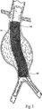
図1Aおよび1Bは、補綴具送達カテーテル10を示す。カテーテル10の目的は、(i)補綴具14を、その配置の前に収容および/または拘束すること(図1Bを参照のこと)、(ii)脈管構造(例えば、中空の身体器官または血管)を通して身体内の所望の位置に補綴具14を送達すること(図2を参照のこと)、ならびに(iii)所望の位置に補綴具14を制御可能に配置すること(図3を参照のこと)である。
(Detailed description of the invention)
(I. Prosthesis delivery catheter)
1A and 1B show a
図示された配置(図3を参照こと)において、補綴具14は、血管内自己拡張式ステント補綴具の形態をとる。この点で、補綴具(単数または複数)14は、実に様々な従来の構成を有し得る。それは、代表的には、ステント48により形成される構造体により支持される、布または何らかの他の血液半透過性の可撓性バリアを備え得る。このステント構造体は、ジグザグ、ヘビ状、拡張した菱形、またはこれらの組み合わせのような任意の従来のステント構成を有し得る。ステント構造体は、補綴具の全長に延び得、そして、いくつかの場合、補綴具の布の構成要素よりも長くあり得る。あるいは、ステント構造体は、例えば、端部にある補綴具のほんの一部のみを覆い得る。ステント構造体は、二股に分かれた脈管領域を処置するように構成される場合(例えば、腹部大動脈瘤の処置、ステント補綴具が腸骨動脈内を延びる場合)、3つ以上の端部を有し得る。特定の例において、ステント構造体は、ステント補綴具の全長に沿って、または、少なくとも全長の大部分に沿って、間隔が空けられ得、ここで、個々のステント構造体は、互いに関して、直接接続されるのではなく、布、または補綴具の他の可撓性構成要素に接続される。さらに、上記ステント構造体が、別々の位置で(例えば、近位首領域において)互いに取り付けられ得ることが企図される。このようなステント構造体は、補綴具に組込まれた場合に一緒に連結される個々のステント、または補綴具への組み込みの前に結合した状態で製造されるステントを備え得る。
In the illustrated arrangement (see FIG. 3), the
ステント48は、弾性的であり得、例えば、形状記憶合金の弾性ステンレス鋼などから構成され得る。弾性について、拡張するとは、代表的には、このステント構造体を拘束から解放し、このステント構造体を移植部位において自己拡張させることを包含する。より詳細に説明されるように、カテーテル10は、このステント構造体に結合された取り外し可能な拘束手段と組合せて、このステント構造体を覆ってシースを配置し、身体への通過の間、このステント構造体を半径方向に圧縮された構成に維持する。この配置において、ステント構造体の自己拡張は、シース上で引き戻して、上記拘束手段を解放してこのステント構造体が、そのより大きな直径の構成をとることを許容することによって達成される。
The
あるいは、このステント構造体は、可鍛性材料(例えば、他の金属の可鍛性ステンレス鋼)から形成され得る。次いで、拡張は、構造体内に半径方向の拡張力を適用して拡張を起こす工程、例えば、拡張を達成するために、ステント構造体内で送達カテーテルを膨張させる工程を包含し得る。この配置において、内部補綴具の位置決めおよび配置は、配置カテーテルと別個であるか、または配置カテーテルに組み込まれた、拡張手段を使用することによって達成され得る。このことは、内部補綴具が血管内に位置決めされ、そしてその血管内の相対的位置を確認する間、部分的に配置されることを可能にする。拡張は、バルーンまたは機械式の拡張デバイスのいずれかにより達成され得る。さらに、この拡張は、内部補綴具が完全に配置され得るまで、内部移植片への血液の力に抵抗することによって、動脈内の内部補綴具の位置を安定させる。さらにあるいは、このステント構造体は、自己拡張式ステントと可鍛性ステント構造体との組合せを備え得る。 Alternatively, the stent structure may be formed from a malleable material (eg, a malleable stainless steel of another metal). Expansion can then include applying a radial expansion force within the structure to cause expansion, eg, inflating a delivery catheter within the stent structure to achieve expansion. In this placement, positioning and placement of the endoprosthesis can be achieved by using an expansion means that is separate from or incorporated into the placement catheter. This allows the endoprosthesis to be positioned within the blood vessel and partially positioned while verifying the relative position within the blood vessel. Expansion can be accomplished by either a balloon or a mechanical expansion device. In addition, this expansion stabilizes the position of the endoprosthesis within the artery by resisting blood forces on the endograft until the endoprosthesis can be fully deployed. Additionally or alternatively, the stent structure may comprise a combination of a self-expanding stent and a malleable stent structure.
図示された実施形態において(図2を参照のこと)、カテーテル10は、身体内腔中のガイドワイヤ12を覆って配置されるとして示される。カテーテル10は、補綴具14を、半径方向に減少した構成で標的化した部位に運ぶ。標的化した部位で、カテーテル10は、半径方向に縮小した補綴具14を解放し、この補綴具14は、半径方向に拡張する(図3を参照のこと)。補綴具14の部分的もしくは完全な拡張または配置の後、1つ以上のファスナーが、望ましくは、ファスナー取り付けアセンブリにより導入され、補綴具14を適所につなぎ止める。ファスナー取り付けアセンブリのさらなる詳細は、米国特許出願第10/307,226号(2002年11月29日出願)に見出され得、この米国特許出願第10/307,226号は、本明細書中に参考として援用される。
In the illustrated embodiment (see FIG. 2), the
補綴具14は、真っ直ぐな形態または二股の形態のいずれかであるようなサイズおよび形状であり得る。図3は、完全に配置された真っ直ぐな補綴具14を示す。図4は、完全に配置された二股の補綴具14を示す。
The
例示の目的のために、図2は、標的化した部位を、腹部大動脈瘤内にあるものとして示す。標的化した部位は、当然、身体内の他の場所であり得る。 For illustrative purposes, FIG. 2 shows the targeted site as being within an abdominal aortic aneurysm. The targeted site can of course be elsewhere in the body.
図1Aおよび1Bに示されるように、カテーテル10は、内側アセンブリ16、外側シース18、およびハンドルアセンブリ20を備える。これらの構成要素は、ここで、個々により詳細に説明される。
As shown in FIGS. 1A and 1B, the
(A.内側アセンブリ)
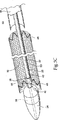
図示された実施形態において(図5Aを参照のこと)、内側アセンブリ16は、中央シャフト22を備え、これは補綴具のためのキャリアとして機能する。この内側アセンブリはまた、カテーテル先端構成要素24、配置の前に半径方向に圧縮した状態で補綴具14の少なくとも一部分を保持するための解放手段または解放機構28、使用の間、中央シャフト22との所望の関係で解放手段28を維持するための保持手段または保持機構26、およびスペーサー30を備える。
(A. Inner assembly)
In the illustrated embodiment (see FIG. 5A), the
図5Aに示される実施形態において、中央シャフト22、保持手段26、解放手段28およびスペーサー30は、外側シース18の境界内に位置する。この点に関して、外側シース18は、キャリア上の補綴具のための囲いとして機能する。この配置において、カテーテル先端構成要素24は、中央シャフト22の遠位端に取り付けられ、そして外側シース18の遠位端は、カテーテル先端構成要素24に隣接して終結する。このようにして、カテーテル先端構成要素24は、外側シース18を越えて外向きに延びる。中央シャフト22、解放機構28および外側シース18は、カテーテル10の近位端でハンドルアセンブリ20に連結する(図1Aを参照のこと)。使用の際に(図5Bを参照のこと)、補綴具14は、カテーテル10の遠位セクションで中央シャフト22と外側シース18との間に規定される空洞32中に収容される(この配置はまた、図1Bに示される)。
In the embodiment shown in FIG. 5A, the
中央シャフト22は、ハンドルアセンブリ20から、カテーテル先端構成要素24に延びる(図1Aを参照のこと)。中央シャフト22は、例えば、ステンレス鋼または他の適切な医療用材料(他の金属またはポリマーを含む)から作製され得る。中央シャフト22は、望ましくは、0.010インチと0.120インチとの間、好ましくは0.03インチと0.06インチとの間、そして最も好ましくは0.04インチと0.05インチとの間の内径を有する、少なくとも1つの内腔36を有する(図5Aを参照のこと)。
A
説明されるように、中央内腔36は、0.038インチまでの直径のガイドワイヤ12の挿入を可能にする。カテーテル先端構成要素24はまた、望ましくは、中央シャフト22内で少なくとも1つの内腔と整列するような構成である、少なくとも1つの内腔38を有する(図5Aを参照のこと)。この内腔38は、中央シャフト22を通り、そしてカテーテル先端構成要素24を通るガイドワイヤ12の挿入を可能にする(図2を参照のこと)。代表的には、この内腔は、0.010インチと0.120インチとの間、好ましくは0.03インチと0.06インチとの間、そして最も好ましくは0.04インチと0.05インチとの間の内径を有する。
As will be described, the
好ましくは、カテーテル先端構成要素24は、可撓性であり、そして長いテーパー状の遠位端およびより短いテーパー状の近位端を有する。カテーテル先端構成要素24の最大直径は、外側シース18の遠位端の外径とほぼ同じである。カテーテル先端構成要素24の遠位端は、ガイドワイヤ12を収容する内腔38から外側シース18の遠位端への滑らかなテーパー状の移行部を提供する。この特徴は、ガイドワイヤ12を覆っての曲がりくねった解剖学的構造を通るカテーテル挿入および進行を補助する。カテーテル先端構成要素24の近位端上のテーパー状セクションは、カテーテル先端構成要素24が、身体からのカテーテル10の除去の間に、補綴具14、周囲の解剖学的構造の部分、または導入器シースなどを不注意で係合することを防ぐ。
Preferably, the
なお図5Aを参照して、保持手段26は、解放手段28を、中央シャフト22との所望の密接な関係で保持する。保持手段26は、解放手段28を中央シャフト22の軸に沿って配向させ、そして解放手段28が、この軸内で長軸方向に移動することを可能にする。図5A、5Bおよび5Cに示される実施形態において、保持手段26は、カテーテル先端構成要素24の近位端の小穴または凹部40、および中央シャフト22と解放手段28との両方を収容するに十分大きい直径を有する管56を備える。図5A、5Bおよび5Cに示される実施形態において、保持手段26の管56は、中央シャフト22を覆ってカテーテル先端構成要素24上の凹部40と整列しかつそれに隣接して位置する。管56は、管56と中央シャフト22との間の三日月形状の内腔42を保持する様式で、中央シャフト22に取り付けられる。解放手段28は、この内腔42を通りかつ凹部40の中へ延びる。
Still referring to FIG. 5A, the holding means 26 holds the release means 28 in the desired close relationship with the
再度図5Aを参照して、スペーサー30は、外側シース18に対する支持を提供し、そして外側シース18内の空間を占めることによりカテーテル10内に閉じ込められる空気の量を減少させる。スペーサー30の遠位端は、望ましくは(図5Bに示されるように)補綴具14の近位端に隣接して終結する。この配置において(図5Bを参照のこと)、補綴具14を収容する空洞32は、カテーテル先端構成要素24の近位端からスペーサー30の遠位端へ延びる。図5Aが示すように、スペーサー30は、中央シャフト22および解放手段28を覆って配置され、そしてスペーサー30の近位端は、ハンドルアセンブリ20に連結される。代表的には、スペーサー30は、外側シース18の内径よりもわずかに小さい外径を有し得る。スペーサー30は、このスペーサー30内での種々の構成要素の通過のための単一の内腔または一列にならぶ複数の内腔を備え得る。
Referring again to FIG. 5A, the
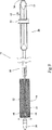
解放手段28は、補綴具14を、配置の前に所望の構成で保持し(図5Bを参照のこと)、そして配置のために補綴具14を選択的に解放する(図5Cを参照のこと)。図示された実施形態において、解放手段28の近位端は、ハンドルアセンブリ20のアクチュエーターまたは制御ボタンまたはノブ46に連結される(図1Aを参照のこと)。図5Bが示すように、解放手段28は、中央シャフト22の外側に沿って、スペーサー30の内部を通って延び、そして補綴具14の内部を通って遠位方向に続く。解放手段28は、補綴具14および保持手段26を通る。
Release means 28 holds the
図5Bが最もよく示すように、補綴具14は、解放手段28によって、中央シャフト22に沿って、カテーテル先端構成要素24の近位端とスペーサー30の遠位端との間を延びる空洞32中に保持される。図示された実施形態において、解放手段28は、中央シャフト22に沿って延びるワイヤ58を備える。ワイヤ58の遠位端は、保持手段26の三日月形状の内腔42を通り、最終的にはカテーテル先端構成要素24の近位端の保持手段26の穴または凹部40中に捕捉される。それによってワイヤ58の遠位端は、中央シャフト22に沿って所望の関係で維持される。ワイヤ58の近位端は、制御ボタン46に結合され、その結果、ボタン46の前向きの移動および後ろ向きの移動が、ワイヤ58を、それぞれ、遠位方向および近位方向に進める。
As best shown in FIG. 5B, the
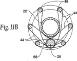
図5Bが示すように(そして、それは、図11A、11Bおよび11Cに、より概略的な形態でさらに示される)、保持手段28は、縫合糸44および/または等価な構造体を備え、それらは補綴具14上の1つ以上のステント48に取り付けられる。図5Bが示すように、ワイヤ58がその最も遠位の位置にあるとき、縫合糸44は、引き続いて、解放手段28のワイヤ58の周りにループ状にされる。(制御ボタン46を使用する)ワイヤ58の近位方向への前進は、図5Cが示すように、縫合糸ループ44からワイヤ58を引き込める。
As FIG. 5B shows (and it is further shown in a more schematic form in FIGS. 11A, 11B and 11C), the retaining means 28 comprises a
図示された実施形態において(図5Bならびに図11A、11B、および11Cを参照のこと)、縫合糸ループ44は、補綴具14の遠位端で1つ以上のステント48に取り付けられる。しかし、縫合糸ループ44は、補綴具14中の他のどこかでステント44に、そして/または同様に補綴具14の他の構成要素に取付けられ得ることが理解されるべきである。
In the illustrated embodiment (see FIG. 5B and FIGS. 11A, 11B, and 11C), the
ちょうど説明された解放手段28の実施形態の縫合糸ループ44およびワイヤ56は、補綴具14を中央シャフトに保持する(図5Bを参照のこと)。縫合糸ループ44およびワイヤ56は、外側シース18が退却されるときに、補綴具14が近位方向に移動することを防ぐ。解放手段28はまた、外側シース18が取り除かれるときに、縫合糸ループ44に取り付けられるステント48を半径方向に圧縮された状態で維持する。縫合糸ループ44およびワイヤ56は、解放手段28が引き込まれてしまうまで、補綴具14の遠位端が自己拡張することを防ぐ。図示される実施形態において、解放手段28の引き込みは、制御ボタン46を作動してワイヤ58を近位方向に動かし、ワイヤ58を穴または凹部40からかつ縫合糸ループ44から離して引き込むことにより、達成される。いったん、解放手段28が引き込まれると、補綴具14の拘束された構成要素は、図5Cに示されるように、自由になり、自己拡張する。
The
図示されかつ説明されるように、解放手段28は、補綴具14の拘束された構成要素に結合される。しかし、解放手段28は、2つ以上の拘束された領域で補綴具14に結合され得、その結果、解放手段28の引き込みが、補綴具を2つ以上の拘束領域で自由にすることが理解されるべきである。解放手段28が、単一より多くの解放要素を備え得ることもまた、理解されるべきである。例えば、複数の個々の解放ワイヤ58が異なる領域で補綴具14に結合され得、その結果、補綴具14の別個の領域の解放が、個々に制御され得る。
As shown and described, the release means 28 is coupled to the constrained component of the
(B.外側シース)
外側シース18はまた、補綴具14上のステント48を拡張することから拘束し、そして身体内での補綴具14の制御された配置を可能にするように機能する。図示された配置において、外側シース18は、ハンドルアセンブリ20上のアクチュエーターまたは襟またはノブ50に連結される。図5Aが示すように、外側シース18は、スペーサー30および補綴具14を覆って遠位方向に延び、カテーテル先端構成要素24の近位端に隣接して終結する。代表的には、外側シース18は、ポリマー管から作製されてもよく、そして構造補強されなくてもよい。
(B. Outer sheath)
The
図示された実施形態において(図5Aを参照のこと)、外側シース18は、カテーテル先端構成要素の外径とスペーサー30の外径とにおける差に起因して、テーパー状である。外側シース18のより大きい直径は、補綴具14の主要本体を収容することを意図され、そしてより小さい直径は、補綴具14の脚部分(単数または複数)が(図4に示される実施形態におけるように)存在する場合、それらを収容する。より小さい直径は、近位方向へハンドルアセンブリ20へと続く。外側シース18のテーパー状の特徴はまた、このカテーテルを通るより良好な血液循環を可能にする。
In the illustrated embodiment (see FIG. 5A), the
(C.ハンドルアセンブリ)
ハンドルアセンブリ20は、操作者に、身体内でのカテーテル10の長軸方向の制御および回転方向の制御を提供し、そして補綴具14を配置するためのアクチュエーターまたは制御手段へのアクセスを提供する。
(C. Handle assembly)
The
図示された実施形態において、ハンドルアセンブリ20は、ハンドル本体52、および外側シース18の近位端に連結される滑りノブまたは襟50、および解放手段28の近位端に取り付けられるノブまたはボタン46を備える。図示された実施形態において、中央シャフト22は、ハンドル内に捕捉され、そしてハンドルの近位端に連結されるガイドワイヤを受容するルアー34を有し、その近位端は、ハンドルアセンブリ20の近位端に位置する。この設計は、外側シース18が退却される間に、補綴具14の位置がハンドル本体52に対して移動することを防ぐ。
In the illustrated embodiment, the
外側シース18を補綴具14から引き込むために(図6および7を参照のこと)、外側シース18の遠位端が、補綴具14を含まなくなるまで、滑りノブ50は、近位方向に移動される(図8を参照のこと)。解放手段28に結合されない補綴具14の一部分(単数または複数)(図示された実施形態において、それは補綴具14の近位領域を備える)は、図8が示すように、自由に自己拡張する。しかし、解放手段58に連結される補綴具14の一部分(図示された実施形態において、この部分は補綴具14の遠位領域を備える)は、図8がまた示すように、外側シース18の引き込みにもかかわらず、依然として、自己拡張から拘束されている。それにより補綴具14のステント構造体は、外側シース18が退却される間、中央シャフト管22に対してしっかりと拘束されて維持される。保持手段26は、外側シース18の退却の間、補綴具14が中央管22に対して動くことを防ぎ、このことは、配置プロセスの間に補綴具14を通る血流を潜在的に最小にする。さらに、説明されるように、補綴具14は、カテーテルから「押し出され」ない。それゆえに、補綴具14は、長軸方向の剛性、または「背骨」を有するステント構造体を有する必要はない。
To retract the
解放手段28を引き込むために(図8および9を参照のこと)、滑りボタン46は、解放手段28の遠位端が拘束手段26から引き込まれるまで、近位方向に動かされる。それにより、補綴具は、図9および5Cが示すように、自由に十分に自己拡張する。説明されるように、補綴具14は、シース18が引き込まれるとき、遠位端から近位端まで直ちには解放されない。外側シース18が退却されるにつれて、補綴具14は、ピンと引張られ、このことは、補綴具をその適切な長さおよびステント間隔へ「伸張する」。遠位のステント(単数または複数)48は、二次的な作動において解放され、これは、(図5C、8および9に示されるように)外側シース18の引き込みの後に続く。それゆえに、補綴具14の遠位端の最終の配置は、配置プロセスの最終工程を構成する。
To retract the release means 28 (see FIGS. 8 and 9), the
ノブ50は、ハンドルアセンブリ20の一部ではない、すなわち外側シース18の上にある別個の構成要素を備え得ることが理解されるべきである。
It should be understood that the
(II.補綴具送達カテーテルの使用)
使用の間、カテーテル10は、(図2が示すように)ガイドワイヤ12を覆って身体内の所望の位置へ導かれる。図示された実施形態において、補綴具14の配置は、2段階プロセスで達成される。第1に、(図6および7が示すように)ハンドルアセンブリ20上のノブまたは襟50を近位方向に引張ることにより、外側シース18が退却され、補綴具14を露出させる。図8が示すように、補綴具14の拘束されていない部分(単数または複数)が、自己拡張する。図6および7が示すように、外側シース18の退却の間、補綴具14は、補綴具14に連結される解放手段28に起因して、中央シャフト22に対するその位置を維持する。
(II. Use of prosthesis delivery catheter)
During use, the
配置プロセスの第2の工程において、外側シース18の引き込みに続いて、ハンドルアセンブリ20上の制御ボタンまたはノブ46は、近位方向に動かされる(図8および9を参照のこと)。このことによって、解放手段28の遠位端が、引き込まされ、そして、(図5Cおよび9が示すように)拘束されたステント(単数または複数)44および補綴具14が全体として、半径方向に自己拡張することが可能になる。図3が示すように、補綴具14は、拡大して、血管または中空の身体器官の内壁に接触する。次いで、カテーテル10は、(図10が示すように)引き込まれ得る。
In the second step of the deployment process, following withdrawal of the
外側シース18の引き込みおよび解放手段28の引き込みは、単一工程のプロセスで達成され得ることが理解されるべきである。この配置において、単一の活性化機構は、外側シース18および解放手段28に一緒に結合され得、その結果、外側シース18および解放手段28は、単一の工程で引き込まれる。
It should be understood that retracting the
(III.代替の実施形態)
(すでに説明されたように)図11A〜11Cに示される実施形態において、解放手段28の可動式構成要素(例えば、ワイヤ58)の遠位端は、拘束手段26により規定され制御される様式で、すなわち、中央シャフト22により担持される管56とカテーテル先端構成要素24の近位端に位置する凹部40との間で、中央シャフト22に沿って延びる。補綴具14に取り付けられる解放手段28の固定構成要素(例えば、縫合糸ループ44)が、解放手段28の可動式構成要素に作動可能に結合されるのは、管56と凹部40との間のこの領域である。この領域からの可動式構成要素58の動きは、固定構成要素44を解放する。拘束手段26の全体的な目的が、達成される。拘束手段26は、解放手段28の可動式構成要素58を、中央シャフト22との所望の作動可能な配置で、および解放手段28の固定構成要素44との所望の作動可能な関係で維持するのに役立ち、その結果、補綴具14の素早くかつ確実な解放が起こる。
III. Alternative Embodiments
In the embodiment shown in FIGS. 11A-11C (as already described), the distal end of the movable component (eg, wire 58) of the release means 28 is in a manner defined and controlled by the restraining means 26. That is, it extends along the
解放手段28および拘束手段26は、この目的を満たすように様々に構成され得る。例えば、図12Aに示される代替の実施形態において、解放手段28の可動式構成要素58の遠位端は、拘束手段26により規定され制御される様式で、すなわち、隣接する、間隔を空けて離れた管60Aと60Bとの間で、カテーテル先端構成要素24によるさらなる支持に頼ることなく、中央シャフト22に沿って延びる。各管60Aおよび60Bは、図11A〜11Cに示される単一の管56と同じ様式で、中央シャフト22を囲む。解放手段28の可動式構成要素58は、これら2つの管60Aと60Bとの間のこの領域で、解放手段28の固定構成要素44と作動可能に結合して保持され、そして素早く確実にこの領域から引かれ得、補綴具14を開放し得る。類似の代替の配置において(図12Bを参照のこと)、解放手段28の可動式構成要素58の遠位端は、隣接する、間隔を空けて離れた管62Aと62Bとの間で、この場合もカテーテル先端構成要素24によるさらなる支持に頼ることなく、中央シャフト22に沿って延びる。図12Bにおいて、管62Aおよび62Bは、中央シャフト22の外部に沿って突出するが、それを取り囲まない。依然として、管62Aまたは62Bのような単一の外部支持管が、所望の場合には、代替的にカテーテル先端構成要素24中の凹部40と混成的な組合わせで使用され得ることが理解されるべきである。
The release means 28 and the restraining means 26 can be variously configured to meet this purpose. For example, in the alternative embodiment shown in FIG. 12A, the distal end of the
別の例示的な代替の実施形態において(図13Aを参照のこと)、解放手段28の可動式構成要素58の遠位端は、中央シャフト22中の内腔66内に延び、シャフト22の開口部64を通って、そしてカテーテル先端構成要素24中の凹部44の中へ出る。解放手段28の可動式構成要素58は、開口部64と凹部40との間のこの領域で、解放手段28の固定構成要素44と作動可能に結合して保持され、そして素早く確実にこの領域から引かれ得、補綴具14を開放し得る。類似の代替の配置において(図13Bを参照のこと)、解放手段28の可動式構成要素58の遠位端は、隣接する、間隔を空けて離れた開口部70と72との間で、中央シャフト22の内腔68内に延びる。可動式構成要素58は、開口部72を出て、カテーテル先端構成要素24中の凹部40に入る。解放手段28の可動式構成要素58は、開口部72と凹部40との間のこの領域で、解放手段28の固定構成要素44と作動可能に結合して保持され、そして素早く確実にこの領域から引かれ得、補綴具14を開放し得る。
In another exemplary alternative embodiment (see FIG. 13A), the distal end of the
さらに別の例示的な代替の実施形態において(図14Aおよび14Bを参照のこと)、拘束手段26は、中央シャフト22によって担持される単一の管74を備え、その管74を通して解放手段28の可動式構成要素58が通過する。管74は、(図14Aおよび14Bが示すように)図12Aに示されるタイプの取り囲む管、または図12Bに示されるタイプの外部管を備え得る。
In yet another exemplary alternative embodiment (see FIGS. 14A and 14B), the restraining means 26 comprises a
この配置において、解放手段28は、カテーテル先端構成要素24の近位端により担持される縫合糸ループ76、および解放手段28の可動式構成要素58の遠位端に担持される切断要素78を備える。縫合糸ループ76は、補綴具14上の縫合糸ループ44を通り、そして切断要素78を通って通過する。解放手段28の可動式構成要素58の遠位端にある切断要素78は、拘束手段26により規定され制御される様式で、すなわち、管74を通ってかつそれを越えて、そして縫合糸ループ44および76と作動可能に結合して、中央シャフト22に沿って延び、これらの縫合糸ループ44および76は、この実施形態において、解放手段28の固定構成要素を備える。このことは、カテーテル先端構成要素24によるさらなる支持に頼ることなく、起こる。(図14Bが示すように)可動式構成要素58の引き込みによって、縫合糸ループ76を通して切断要素78が移動し、縫合糸ループ76を切断し、そして補綴具14を解放する。
In this arrangement, the release means 28 comprises a
さらに別の例示的な代替の実施形態(図15Aおよび15Bを参照のこと)、拘束手段26は、中央シャフト22によって担持される単一の管80を備え、その管80を通して解放手段28の可動式構成要素58が通過する。図14Aおよび14Bに示される管74のように、管80は、(図15Aおよび15Bが示すように)図12Aに示されるタイプの取り囲む管、または図12Bに示されるタイプの外部管を備え得る。
In yet another exemplary alternative embodiment (see FIGS. 15A and 15B), the restraining means 26 comprises a
この配置において、解放手段28は、解放手段28の可動式構成要素58の遠位端に担持されるくさび要素84を備える。このくさび要素84は、カテーテル先端構成要素24の近位端に形成される噛み合うくさび表面86内に入れ子になる。可動式構成要素58が前進すると、くさび要素84は、(図15Aが示すように)くさび表面86内でぴったりと噛み合うように動き、そして(図15Bが示すように)くさび表面86からぴったりした噛み合いからはずれるように動く。この配置における解放手段28は、縫合糸ループ82または82’の代替の実施形態をさらに備え、これらの縫合糸ループは、図15Aが示すように、要素84および表面86がぴったり噛み合っている場合、くさび要素84とくさび表面86との間で、挟まれる。縫合糸ループ82の実施形態は、補綴具ステント48により担持される閉じたループ82を備える。縫合糸ループ82’の実施形態は、カテーテル先端構成要素24の近位端により担持され、補綴具ステント48を通ってループを形成する開いたループ82’を備える。縫合糸ループ82または82’のいずれかの実施形態が、くさび要素84とへこんだ表面86との間で挟まれる場合、(図15Aが示すように)補綴具14の拡張は拘束されている。解放手段28の可動式構成要素58が近位方向に進められるとき、くさび要素84は、くさび表面86内でのぴったりした噛み合いから自由にされ、ループ82および82’を自由にし、図15Bが示すように、それによって、拡張のために補綴具14を解放する。
In this arrangement, the release means 28 comprises a
本発明の好ましい実施形態が、完全な開示を示す目的のために、そして説明および明瞭にするために、上に詳細に説明される。当業者は、本開示の範囲および趣旨内で他の改変を想定する。 Preferred embodiments of the present invention are described above in detail for the purpose of providing a complete disclosure and for the sake of explanation and clarity. Those skilled in the art will envision other modifications within the scope and spirit of the present disclosure.
上に記載された本発明の実施形態は、単にその原理を記載するためだけであり、限定されるべきではない。その代わりに、本発明の範囲は、添付の特許請求の範囲(それらの等価物を含む)の範囲から、決定される。 The embodiments of the present invention described above are merely to describe the principles and should not be limited. Instead, the scope of the invention is determined from the scope of the appended claims, including their equivalents.
Claims (10)
血管内配置のための自己拡張式補綴具(14)であって、遠位端および近位端を有し、半径方向に低減された形態から半径方向に拡大された形態まで自己拡張するように適合されている自己拡張式補綴具;および
該血管中への導入のためのサイズおよび形態であるカテーテル(10)を備える、該補綴具を送達するための装置であって、該カテーテルが、ハンドル(20)を含む近位端、該補綴具を保持する形態のキャリア(22)を含む遠位端、該半径方向に低減された形態で該キャリア上の該補綴具の遠位端を保持するように作動可能である解放機構(28)、遠位直径と近位直径との間でテーパー状であり、そして該半径方向に低減された形態にあるとき該補綴具を囲む進行位置と、該補綴具のない引き込まれた位置との間で近位方向に移動可能である外側シース(18)であって、該遠位直径が該近位直径より大きい外側シース、該外側シースを支持するスペーサー(30)、該テーパー状の外側シースに連結されたハンドル上の第1のアクチュエーター(50)、該解放機構に連結された該ハンドル上の第2のアクチュエーター(46)を有し、該第1のアクチュエーターが該テーパー状の外側シースを該進行位置と該引き込まれた位置との間で移動するように作動可能であり、該第2のアクチュエーターが該補綴具の遠位端を該キャリアから解放するように該解放機構を起動するように作動可能である、装置;および
該補綴具を定着して係留するために該補綴具にファスナーを導入するためのファスナー取り付けアセンブリ、を備えるシステム。An endovascular prosthesis system comprising:
Self-expanding prosthesis (14) for endovascular placement, having a distal end and a proximal end, to self-expand from a radially reduced configuration to a radially expanded configuration A device for delivering a prosthesis comprising a self-expanding prosthesis adapted; and a catheter (10) that is sized and configured for introduction into the blood vessel, the catheter comprising a handle A proximal end including (20), a distal end including a carrier (22) configured to hold the prosthesis, and a distal end of the prosthesis on the carrier in a radially reduced configuration actuatable and is release mechanism (28) as a tapered between distal diameter and the proximal diameter, and the traveling position surrounding the prosthesis when in the reduced form to the radial direction, the Proximal to retracted position without prosthesis Is movable an outer sheath (18), the handle distal large diameter outer sheath than the proximal diameter, spacer for supporting the outer sheath (30), coupled to said tapered outer sheath A first actuator (50) on the top, a second actuator (46) on the handle coupled to the release mechanism, the first actuator passing the tapered outer sheath to the advanced position and the Operable to move between retracted positions and operable to activate the release mechanism such that the second actuator releases the distal end of the prosthesis from the carrier A fastener mounting assembly for introducing a fastener into the prosthesis to anchor and anchor the prosthesis.
Applications Claiming Priority (3)
| Application Number | Priority Date | Filing Date | Title |
|---|---|---|---|
| US10/692,283 | 2003-10-23 | ||
| US10/692,283 US7147657B2 (en) | 2003-10-23 | 2003-10-23 | Prosthesis delivery systems and methods |
| PCT/US2004/027587 WO2005044073A2 (en) | 2003-10-23 | 2004-08-25 | Prosthesis delivery systems and methods |
Related Child Applications (1)
| Application Number | Title | Priority Date | Filing Date |
|---|---|---|---|
| JP2010139939A Division JP2010227613A (en) | 2003-10-23 | 2010-06-18 | Prosthesis delivery systems and prosthesis delivery methods |
Publications (3)
| Publication Number | Publication Date |
|---|---|
| JP2007508893A JP2007508893A (en) | 2007-04-12 |
| JP2007508893A5 JP2007508893A5 (en) | 2007-08-30 |
| JP4912883B2 true JP4912883B2 (en) | 2012-04-11 |
Family
ID=34522082
Family Applications (2)
| Application Number | Title | Priority Date | Filing Date |
|---|---|---|---|
| JP2006536615A Expired - Fee Related JP4912883B2 (en) | 2003-10-23 | 2004-08-25 | Prosthetic device delivery system and prosthetic device delivery method |
| JP2010139939A Pending JP2010227613A (en) | 2003-10-23 | 2010-06-18 | Prosthesis delivery systems and prosthesis delivery methods |
Family Applications After (1)
| Application Number | Title | Priority Date | Filing Date |
|---|---|---|---|
| JP2010139939A Pending JP2010227613A (en) | 2003-10-23 | 2010-06-18 | Prosthesis delivery systems and prosthesis delivery methods |
Country Status (11)
| Country | Link |
|---|---|
| US (3) | US7147657B2 (en) |
| EP (1) | EP1682039B1 (en) |
| JP (2) | JP4912883B2 (en) |
| CN (1) | CN1870950B (en) |
| AT (1) | ATE438362T1 (en) |
| AU (1) | AU2004287353A1 (en) |
| CA (1) | CA2539265A1 (en) |
| DE (1) | DE602004022446D1 (en) |
| DK (1) | DK1682039T3 (en) |
| ES (1) | ES2356352T3 (en) |
| WO (1) | WO2005044073A2 (en) |
Families Citing this family (186)
| Publication number | Priority date | Publication date | Assignee | Title |
|---|---|---|---|---|
| US7491232B2 (en) * | 1998-09-18 | 2009-02-17 | Aptus Endosystems, Inc. | Catheter-based fastener implantation apparatus and methods with implantation force resolution |
| US6960217B2 (en) | 2001-11-28 | 2005-11-01 | Aptus Endosystems, Inc. | Endovascular aneurysm repair system |
| JP4512362B2 (en) | 2001-07-06 | 2010-07-28 | アンギオメット ゲゼルシャフト ミット ベシュレンクテル ハフツング ウント コムパニー メディツィンテヒニク コマンデイトゲゼルシャフト | Self-expanding stent rapid pusher assembly and delivery system with stent replacement configuration |
| GB0123633D0 (en) | 2001-10-02 | 2001-11-21 | Angiomed Ag | Stent delivery system |
| US20070073389A1 (en) | 2001-11-28 | 2007-03-29 | Aptus Endosystems, Inc. | Endovascular aneurysm devices, systems, and methods |
| US7147657B2 (en) | 2003-10-23 | 2006-12-12 | Aptus Endosystems, Inc. | Prosthesis delivery systems and methods |
| US20090112303A1 (en) * | 2001-11-28 | 2009-04-30 | Lee Bolduc | Devices, systems, and methods for endovascular staple and/or prosthesis delivery and implantation |
| US8231639B2 (en) | 2001-11-28 | 2012-07-31 | Aptus Endosystems, Inc. | Systems and methods for attaching a prosthesis within a body lumen or hollow organ |
| US20050177180A1 (en) | 2001-11-28 | 2005-08-11 | Aptus Endosystems, Inc. | Devices, systems, and methods for supporting tissue and/or structures within a hollow body organ |
| US9320503B2 (en) | 2001-11-28 | 2016-04-26 | Medtronic Vascular, Inc. | Devices, system, and methods for guiding an operative tool into an interior body region |
| US20110087320A1 (en) * | 2001-11-28 | 2011-04-14 | Aptus Endosystems, Inc. | Devices, Systems, and Methods for Prosthesis Delivery and Implantation, Including a Prosthesis Assembly |
| US7867252B2 (en) | 2002-06-11 | 2011-01-11 | Tyco Healthcare Group Lp | Hernia mesh tacks |
| GB0327306D0 (en) * | 2003-11-24 | 2003-12-24 | Angiomed Gmbh & Co | Catheter device |
| WO2004062458A2 (en) | 2003-01-15 | 2004-07-29 | Angiomed Gmbh & C0. Medizintechnik Kg | Trans-luminal surgical device |
| ES2370246T3 (en) | 2003-06-13 | 2011-12-13 | Tyco Healthcare Group Lp | INTERCONNECTION OF MULTIPLE ELEMENTS FOR SURGICAL INSTRUMENT AND ABSORBABLE SCREW HOLDER. |
| US8926637B2 (en) | 2003-06-13 | 2015-01-06 | Covidien Lp | Multiple member interconnect for surgical instrument and absorbable screw fastener |
| US9198786B2 (en) | 2003-09-03 | 2015-12-01 | Bolton Medical, Inc. | Lumen repair device with capture structure |
| US11259945B2 (en) | 2003-09-03 | 2022-03-01 | Bolton Medical, Inc. | Dual capture device for stent graft delivery system and method for capturing a stent graft |
| US20080264102A1 (en) | 2004-02-23 | 2008-10-30 | Bolton Medical, Inc. | Sheath Capture Device for Stent Graft Delivery System and Method for Operating Same |
| US8500792B2 (en) | 2003-09-03 | 2013-08-06 | Bolton Medical, Inc. | Dual capture device for stent graft delivery system and method for capturing a stent graft |
| US7763063B2 (en) | 2003-09-03 | 2010-07-27 | Bolton Medical, Inc. | Self-aligning stent graft delivery system, kit, and method |
| US8292943B2 (en) | 2003-09-03 | 2012-10-23 | Bolton Medical, Inc. | Stent graft with longitudinal support member |
| US20070198078A1 (en) | 2003-09-03 | 2007-08-23 | Bolton Medical, Inc. | Delivery system and method for self-centering a Proximal end of a stent graft |
| US11596537B2 (en) | 2003-09-03 | 2023-03-07 | Bolton Medical, Inc. | Delivery system and method for self-centering a proximal end of a stent graft |
| US10478179B2 (en) | 2004-04-27 | 2019-11-19 | Covidien Lp | Absorbable fastener for hernia mesh fixation |
| AU2005262541B2 (en) * | 2004-06-16 | 2011-04-21 | Cook Incorporated | Thoracic deployment device and stent graft |
| US7678121B1 (en) | 2004-12-23 | 2010-03-16 | Cardica, Inc. | Surgical stapling tool |
| US7462185B1 (en) * | 2004-12-23 | 2008-12-09 | Cardican Inc. | Intravascular stapling tool |
| WO2006097931A2 (en) | 2005-03-17 | 2006-09-21 | Valtech Cardio, Ltd. | Mitral valve treatment techniques |
| US7344544B2 (en) | 2005-03-28 | 2008-03-18 | Cardica, Inc. | Vascular closure system |
| US8951285B2 (en) | 2005-07-05 | 2015-02-10 | Mitralign, Inc. | Tissue anchor, anchoring system and methods of using the same |
| US8123795B1 (en) | 2005-10-03 | 2012-02-28 | Cardica, Inc. | System for attaching an abdominal aortic stent or the like |
| CN101466316B (en) | 2005-10-20 | 2012-06-27 | 阿普特斯内系统公司 | Devices systems and methods for prosthesis delivery and implantation including the use of a fastener tool |
| ES2562413T3 (en) * | 2006-05-12 | 2016-03-04 | Covidien Lp | Implant and implant delivery system with multiple mutual marker interlocks |
| US8252036B2 (en) | 2006-07-31 | 2012-08-28 | Syntheon Cardiology, Llc | Sealable endovascular implants and methods for their use |
| US9585743B2 (en) | 2006-07-31 | 2017-03-07 | Edwards Lifesciences Cardiaq Llc | Surgical implant devices and methods for their manufacture and use |
| US7875053B2 (en) * | 2006-09-15 | 2011-01-25 | Cardica, Inc. | Apparatus and method for closure of patent foramen ovale |
| AU2007325652B2 (en) | 2006-11-30 | 2012-07-12 | Cook Medical Technologies Llc | Implant release mechanism |
| US9883943B2 (en) | 2006-12-05 | 2018-02-06 | Valtech Cardio, Ltd. | Implantation of repair devices in the heart |
| US11259924B2 (en) | 2006-12-05 | 2022-03-01 | Valtech Cardio Ltd. | Implantation of repair devices in the heart |
| US11660190B2 (en) | 2007-03-13 | 2023-05-30 | Edwards Lifesciences Corporation | Tissue anchors, systems and methods, and devices |
| US9149379B2 (en) * | 2007-07-16 | 2015-10-06 | Cook Medical Technologies Llc | Delivery device |
| US9566178B2 (en) * | 2010-06-24 | 2017-02-14 | Edwards Lifesciences Cardiaq Llc | Actively controllable stent, stent graft, heart valve and method of controlling same |
| WO2009023221A1 (en) * | 2007-08-13 | 2009-02-19 | William A. Cook Australia Pty. Ltd. | Deployment device |
| US8512396B2 (en) * | 2007-09-11 | 2013-08-20 | Laboratoires Perouse | Device for treating a blood circulation conduit |
| US20090093826A1 (en) * | 2007-10-05 | 2009-04-09 | Cardica, Inc. | Patent Foramen Ovale Closure System |
| US9180030B2 (en) | 2007-12-26 | 2015-11-10 | Cook Medical Technologies Llc | Low profile non-symmetrical stent |
| GB2475494B (en) | 2009-11-18 | 2011-11-23 | Cook William Europ | Stent graft and introducer assembly |
| US9226813B2 (en) | 2007-12-26 | 2016-01-05 | Cook Medical Technologies Llc | Low profile non-symmetrical stent |
| US8574284B2 (en) | 2007-12-26 | 2013-11-05 | Cook Medical Technologies Llc | Low profile non-symmetrical bare alignment stents with graft |
| GB2476451A (en) | 2009-11-19 | 2011-06-29 | Cook William Europ | Stent Graft |
| US8382829B1 (en) | 2008-03-10 | 2013-02-26 | Mitralign, Inc. | Method to reduce mitral regurgitation by cinching the commissure of the mitral valve |
| US10813779B2 (en) * | 2008-04-25 | 2020-10-27 | CARDINAL HEALTH SWITZERLAND 515 GmbH | Stent attachment and deployment mechanism |
| US20100049294A1 (en) | 2008-06-04 | 2010-02-25 | Zukowski Stanislaw L | Controlled deployable medical device and method of making the same |
| CA2725736C (en) | 2008-06-04 | 2013-09-17 | Gore Enterprise Holdings, Inc. | Controlled deployable medical device and method of making the same |
| GB0810749D0 (en) | 2008-06-11 | 2008-07-16 | Angiomed Ag | Catherter delivery device |
| US9750625B2 (en) | 2008-06-11 | 2017-09-05 | C.R. Bard, Inc. | Catheter delivery device |
| WO2010005524A2 (en) | 2008-06-30 | 2010-01-14 | Bolton Medical, Inc. | Abdominal aortic aneurysms: systems and methods of use |
| US8652202B2 (en) | 2008-08-22 | 2014-02-18 | Edwards Lifesciences Corporation | Prosthetic heart valve and delivery apparatus |
| CA2739961A1 (en) | 2008-10-10 | 2010-04-15 | Sadra Medical, Inc. | Medical devices and delivery systems for delivering medical devices |
| CA2740867C (en) | 2008-10-16 | 2018-06-12 | Aptus Endosystems, Inc. | Devices, systems, and methods for endovascular staple and/or prosthesis delivery and implantation |
| US8545553B2 (en) | 2009-05-04 | 2013-10-01 | Valtech Cardio, Ltd. | Over-wire rotation tool |
| US10517719B2 (en) | 2008-12-22 | 2019-12-31 | Valtech Cardio, Ltd. | Implantation of repair devices in the heart |
| US8241351B2 (en) | 2008-12-22 | 2012-08-14 | Valtech Cardio, Ltd. | Adjustable partial annuloplasty ring and mechanism therefor |
| US8926696B2 (en) | 2008-12-22 | 2015-01-06 | Valtech Cardio, Ltd. | Adjustable annuloplasty devices and adjustment mechanisms therefor |
| US8715342B2 (en) | 2009-05-07 | 2014-05-06 | Valtech Cardio, Ltd. | Annuloplasty ring with intra-ring anchoring |
| EP2391309B1 (en) * | 2008-12-30 | 2018-04-04 | Cook Medical Technologies LLC | Delivery device |
| US20100174292A1 (en) * | 2009-01-07 | 2010-07-08 | Vanderbilt University | Surgical instrument for placing a prosthesis into a target area of a living subject |
| US8858610B2 (en) * | 2009-01-19 | 2014-10-14 | W. L. Gore & Associates, Inc. | Forced deployment sequence |
| US8876807B2 (en) | 2009-01-19 | 2014-11-04 | W. L. Gore & Associates, Inc. | Forced deployment sequence |
| US20100204717A1 (en) * | 2009-02-12 | 2010-08-12 | Cardica, Inc. | Surgical Device for Multiple Clip Application |
| US8353956B2 (en) | 2009-02-17 | 2013-01-15 | Valtech Cardio, Ltd. | Actively-engageable movement-restriction mechanism for use with an annuloplasty structure |
| ES2812228T3 (en) * | 2009-03-13 | 2021-03-16 | Bolton Medical Inc | System for deploying an endoluminal prosthesis at a surgical site |
| GB2469072A (en) * | 2009-03-31 | 2010-10-06 | Royal Brompton & Harefield Nhs | Guidewire with Anchor for a catheter |
| US9968452B2 (en) | 2009-05-04 | 2018-05-15 | Valtech Cardio, Ltd. | Annuloplasty ring delivery cathethers |
| US7875029B1 (en) | 2009-05-04 | 2011-01-25 | Cardica, Inc. | Surgical device switchable between clip application and coagulation modes |
| WO2010137583A1 (en) * | 2009-05-27 | 2010-12-02 | 川澄化学工業株式会社 | Placement device for tubular medical treatment instrument and front tip of placement device for tubular medical treatment instrument |
| US8771333B2 (en) | 2009-06-23 | 2014-07-08 | Cordis Corporation | Stent-graft securement device |
| US9180007B2 (en) | 2009-10-29 | 2015-11-10 | Valtech Cardio, Ltd. | Apparatus and method for guide-wire based advancement of an adjustable implant |
| US10098737B2 (en) | 2009-10-29 | 2018-10-16 | Valtech Cardio, Ltd. | Tissue anchor for annuloplasty device |
| US9757263B2 (en) * | 2009-11-18 | 2017-09-12 | Cook Medical Technologies Llc | Stent graft and introducer assembly |
| DE102009055969A1 (en) * | 2009-11-27 | 2011-06-01 | Transcatheter Technologies Gmbh | Device and set for folding or unfolding a medical implant and method |
| ES2577853T3 (en) | 2009-12-01 | 2016-07-19 | Altura Medical, Inc. | Modular endograft devices |
| EP2506777B1 (en) | 2009-12-02 | 2020-11-25 | Valtech Cardio, Ltd. | Combination of spool assembly coupled to a helical anchor and delivery tool for implantation thereof |
| CA2788328C (en) * | 2010-01-29 | 2015-12-08 | Cook Medical Technologies Llc | Mechanically expandable delivery and dilation systems |
| US8926692B2 (en) * | 2010-04-09 | 2015-01-06 | Medtronic, Inc. | Transcatheter prosthetic heart valve delivery device with partial deployment and release features and methods |
| EP3685807A1 (en) | 2010-06-24 | 2020-07-29 | Cardinal Health Switzerland 515 GmbH | Apparatus for and method of pulling a tensile member from a medical device |
| EP2598086B1 (en) | 2010-07-30 | 2016-09-21 | Cook Medical Technologies LLC | Controlled release and recapture prosthetic deployment device |
| US10321998B2 (en) | 2010-09-23 | 2019-06-18 | Transmural Systems Llc | Methods and systems for delivering prostheses using rail techniques |
| GB2485762B (en) * | 2010-11-12 | 2012-12-05 | Cook Medical Technologies Llc | Introducer assembly and dilator tip therefor |
| JP2012139471A (en) * | 2011-01-06 | 2012-07-26 | Nippon Zeon Co Ltd | Stent delivery apparatus |
| US9744033B2 (en) | 2011-04-01 | 2017-08-29 | W.L. Gore & Associates, Inc. | Elastomeric leaflet for prosthetic heart valves |
| US10117765B2 (en) | 2011-06-14 | 2018-11-06 | W.L. Gore Associates, Inc | Apposition fiber for use in endoluminal deployment of expandable implants |
| US10792152B2 (en) | 2011-06-23 | 2020-10-06 | Valtech Cardio, Ltd. | Closed band for percutaneous annuloplasty |
| US9554806B2 (en) | 2011-09-16 | 2017-01-31 | W. L. Gore & Associates, Inc. | Occlusive devices |
| US9549817B2 (en) * | 2011-09-22 | 2017-01-24 | Transmural Systems Llc | Devices, systems and methods for repairing lumenal systems |
| US9827093B2 (en) | 2011-10-21 | 2017-11-28 | Edwards Lifesciences Cardiaq Llc | Actively controllable stent, stent graft, heart valve and method of controlling same |
| US8945146B2 (en) | 2011-10-24 | 2015-02-03 | Medtronic, Inc. | Delivery system assemblies and associated methods for implantable medical devices |
| US8858623B2 (en) | 2011-11-04 | 2014-10-14 | Valtech Cardio, Ltd. | Implant having multiple rotational assemblies |
| US9724192B2 (en) | 2011-11-08 | 2017-08-08 | Valtech Cardio, Ltd. | Controlled steering functionality for implant-delivery tool |
| US9877858B2 (en) | 2011-11-14 | 2018-01-30 | W. L. Gore & Associates, Inc. | External steerable fiber for use in endoluminal deployment of expandable devices |
| US9782282B2 (en) | 2011-11-14 | 2017-10-10 | W. L. Gore & Associates, Inc. | External steerable fiber for use in endoluminal deployment of expandable devices |
| US8721587B2 (en) | 2011-11-17 | 2014-05-13 | Medtronic, Inc. | Delivery system assemblies and associated methods for implantable medical devices |
| US9216293B2 (en) | 2011-11-17 | 2015-12-22 | Medtronic, Inc. | Delivery system assemblies for implantable medical devices |
| CN102488576B (en) * | 2011-11-25 | 2014-07-16 | 北京华脉泰科医疗器械有限公司 | Convey and release device for covered stents |
| US9510945B2 (en) * | 2011-12-20 | 2016-12-06 | Boston Scientific Scimed Inc. | Medical device handle |
| JP6222780B2 (en) | 2012-02-22 | 2017-11-01 | エドワーズ ライフサイエンシーズ カーディアック エルエルシー | Actively controllable stent, stent graft, heart valve, and method for controlling them |
| US9375308B2 (en) | 2012-03-13 | 2016-06-28 | W. L. Gore & Associates, Inc. | External steerable fiber for use in endoluminal deployment of expandable devices |
| EP3141223A1 (en) | 2012-04-12 | 2017-03-15 | Bolton Medical, Inc. | Vascular prosthetic delivery device |
| JP6118894B2 (en) * | 2012-05-16 | 2017-04-19 | エッチエルティ インコーポレイテッドHlt, Inc. | Inverted transfer device and method for prosthesis |
| US9173756B2 (en) | 2012-06-13 | 2015-11-03 | Cook Medical Technologies Llc | Systems and methods for deploying a portion of a stent using at least one coiled member |
| US9144510B2 (en) | 2012-06-13 | 2015-09-29 | Cook Medical Technologies Llc | Systems and methods for deploying a portion of a stent using at least one coiled member |
| WO2014026173A1 (en) | 2012-08-10 | 2014-02-13 | Cragg Andrew H | Stent delivery systems and associated methods |
| EP2900150B1 (en) | 2012-09-29 | 2018-04-18 | Mitralign, Inc. | Plication lock delivery system |
| US9949828B2 (en) | 2012-10-23 | 2018-04-24 | Valtech Cardio, Ltd. | Controlled steering functionality for implant-delivery tool |
| US10376266B2 (en) | 2012-10-23 | 2019-08-13 | Valtech Cardio, Ltd. | Percutaneous tissue anchor techniques |
| WO2014087402A1 (en) | 2012-12-06 | 2014-06-12 | Valtech Cardio, Ltd. | Techniques for guide-wire based advancement of a tool |
| US9655756B2 (en) | 2012-12-21 | 2017-05-23 | Cook Medical Technologies Llc | Systems and methods for deploying a portion of a stent using an auger-style device |
| US9687373B2 (en) | 2012-12-21 | 2017-06-27 | Cook Medical Technologies Llc | Systems and methods for securing and releasing a portion of a stent |
| US10350096B2 (en) * | 2012-12-26 | 2019-07-16 | Cook Medical Technologies Llc | Expandable stent-graft system having diameter reducing connectors |
| US9351733B2 (en) | 2013-01-18 | 2016-05-31 | Covidien Lp | Surgical fastener applier |
| WO2014134183A1 (en) | 2013-02-26 | 2014-09-04 | Mitralign, Inc. | Devices and methods for percutaneous tricuspid valve repair |
| US9358010B2 (en) | 2013-03-12 | 2016-06-07 | Covidien Lp | Flex cable and spring-loaded tube for tacking device |
| US9308108B2 (en) | 2013-03-13 | 2016-04-12 | Cook Medical Technologies Llc | Controlled release and recapture stent-deployment device |
| US10449333B2 (en) | 2013-03-14 | 2019-10-22 | Valtech Cardio, Ltd. | Guidewire feeder |
| US9867620B2 (en) | 2013-03-14 | 2018-01-16 | Covidien Lp | Articulation joint for apparatus for endoscopic procedures |
| WO2014144809A1 (en) | 2013-03-15 | 2014-09-18 | Altura Medical, Inc. | Endograft device delivery systems and associated methods |
| US9439751B2 (en) | 2013-03-15 | 2016-09-13 | Bolton Medical, Inc. | Hemostasis valve and delivery systems |
| CN105283214B (en) | 2013-03-15 | 2018-10-16 | 北京泰德制药股份有限公司 | Translate conduit, system and its application method |
| US11911258B2 (en) | 2013-06-26 | 2024-02-27 | W. L. Gore & Associates, Inc. | Space filling devices |
| US9351728B2 (en) | 2013-06-28 | 2016-05-31 | Covidien Lp | Articulating apparatus for endoscopic procedures |
| US9668730B2 (en) | 2013-06-28 | 2017-06-06 | Covidien Lp | Articulating apparatus for endoscopic procedures with timing system |
| US10085746B2 (en) | 2013-06-28 | 2018-10-02 | Covidien Lp | Surgical instrument including rotating end effector and rotation-limiting structure |
| US9358004B2 (en) | 2013-06-28 | 2016-06-07 | Covidien Lp | Articulating apparatus for endoscopic procedures |
| US20150032130A1 (en) | 2013-07-24 | 2015-01-29 | Covidien Lp | Expanding absorbable tack |
| US10070857B2 (en) | 2013-08-31 | 2018-09-11 | Mitralign, Inc. | Devices and methods for locating and implanting tissue anchors at mitral valve commissure |
| US9925045B2 (en) | 2013-10-21 | 2018-03-27 | Medtronic Vascular Galway | Systems, devices and methods for transcatheter valve delivery |
| US10299793B2 (en) | 2013-10-23 | 2019-05-28 | Valtech Cardio, Ltd. | Anchor magazine |
| US9610162B2 (en) | 2013-12-26 | 2017-04-04 | Valtech Cardio, Ltd. | Implantation of flexible implant |
| US10058315B2 (en) | 2014-03-27 | 2018-08-28 | Transmural Systems Llc | Devices and methods for closure of transvascular or transcameral access ports |
| US10335146B2 (en) | 2014-04-02 | 2019-07-02 | Coviden Lp | Surgical fastener applying apparatus, kits and methods for endoscopic procedures |
| FR3023703B1 (en) | 2014-07-17 | 2021-01-29 | Cormove | BLOOD CIRCULATION DUCT TREATMENT DEVICE |
| EP4331503A2 (en) | 2014-10-14 | 2024-03-06 | Edwards Lifesciences Innovation (Israel) Ltd. | Leaflet-restraining techniques |
| US10016293B2 (en) | 2014-12-29 | 2018-07-10 | Cook Medical Technologies Llc | Prosthesis delivery systems having an atraumatic tip for use with trigger wires |
| CN107427374B (en) | 2015-01-11 | 2019-10-29 | 爱思赛瑞斯医疗有限责任公司 | Mixing arrangement and its application method for surgery aorta reparation |
| US20160256269A1 (en) | 2015-03-05 | 2016-09-08 | Mitralign, Inc. | Devices for treating paravalvular leakage and methods use thereof |
| WO2016168176A1 (en) | 2015-04-13 | 2016-10-20 | Cook Medical Technologies Llc | Axial lock and release stent deployment system |
| CR20170480A (en) | 2015-04-30 | 2018-02-21 | Valtech Cardio Ltd | Annuloplasty technologies |
| CN107847232B (en) | 2015-05-14 | 2022-05-10 | W.L.戈尔及同仁股份有限公司 | Device for occluding an atrial appendage |
| EP3297584A1 (en) * | 2015-05-20 | 2018-03-28 | Cook Medical Technologies LLC | Stent delivery system |
| ES2921535T3 (en) | 2015-06-18 | 2022-08-29 | Ascyrus Medical Llc | Branch aortic graft |
| US10779940B2 (en) | 2015-09-03 | 2020-09-22 | Boston Scientific Scimed, Inc. | Medical device handle |
| US10426482B2 (en) | 2015-09-15 | 2019-10-01 | The United States Of America, As Represented By The Secretary, Department Of Health And Human Services | Devices and methods for effectuating percutaneous Glenn and Fontan procedures |
| WO2017117370A2 (en) | 2015-12-30 | 2017-07-06 | Mitralign, Inc. | System and method for reducing tricuspid regurgitation |
| US10751182B2 (en) | 2015-12-30 | 2020-08-25 | Edwards Lifesciences Corporation | System and method for reshaping right heart |
| US10799677B2 (en) | 2016-03-21 | 2020-10-13 | Edwards Lifesciences Corporation | Multi-direction steerable handles for steering catheters |
| US10799676B2 (en) | 2016-03-21 | 2020-10-13 | Edwards Lifesciences Corporation | Multi-direction steerable handles for steering catheters |
| US11219746B2 (en) | 2016-03-21 | 2022-01-11 | Edwards Lifesciences Corporation | Multi-direction steerable handles for steering catheters |
| US10702274B2 (en) | 2016-05-26 | 2020-07-07 | Edwards Lifesciences Corporation | Method and system for closing left atrial appendage |
| GB201611910D0 (en) | 2016-07-08 | 2016-08-24 | Valtech Cardio Ltd | Adjustable annuloplasty device with alternating peaks and troughs |
| US10617409B2 (en) | 2016-10-21 | 2020-04-14 | Covidien Lp | Surgical end effectors |
| US10743859B2 (en) | 2016-10-21 | 2020-08-18 | Covidien Lp | Surgical end effectors |
| US11298123B2 (en) | 2016-10-21 | 2022-04-12 | Covidien Lp | Surgical end effectors |
| US10888309B2 (en) | 2017-01-31 | 2021-01-12 | Covidien Lp | Surgical fastener devices with geometric tubes |
| WO2018175048A1 (en) | 2017-03-24 | 2018-09-27 | Ascyrus Medical, Llc | Multi-spiral self-expanding stent and methods of making and using the same |
| ES2906137T3 (en) | 2017-04-18 | 2022-04-13 | Edwards Lifesciences Corp | Heart valve sealing devices and delivery devices therefor |
| US11224511B2 (en) | 2017-04-18 | 2022-01-18 | Edwards Lifesciences Corporation | Heart valve sealing devices and delivery devices therefor |
| US11045627B2 (en) | 2017-04-18 | 2021-06-29 | Edwards Lifesciences Corporation | Catheter system with linear actuation control mechanism |
| US10959846B2 (en) | 2017-05-10 | 2021-03-30 | Edwards Lifesciences Corporation | Mitral valve spacer device |
| US11173023B2 (en) | 2017-10-16 | 2021-11-16 | W. L. Gore & Associates, Inc. | Medical devices and anchors therefor |
| US10835221B2 (en) | 2017-11-02 | 2020-11-17 | Valtech Cardio, Ltd. | Implant-cinching devices and systems |
| US11135062B2 (en) | 2017-11-20 | 2021-10-05 | Valtech Cardio Ltd. | Cinching of dilated heart muscle |
| EP3743015A1 (en) | 2018-01-24 | 2020-12-02 | Valtech Cardio, Ltd. | Contraction of an annuloplasty structure |
| WO2019145941A1 (en) | 2018-01-26 | 2019-08-01 | Valtech Cardio, Ltd. | Techniques for facilitating heart valve tethering and chord replacement |
| US11298126B2 (en) | 2018-05-02 | 2022-04-12 | Covidien Lp | Shipping wedge for end effector installation onto surgical devices |
| US11116500B2 (en) | 2018-06-28 | 2021-09-14 | Covidien Lp | Surgical fastener applying device, kits and methods for endoscopic procedures |
| CR20210020A (en) | 2018-07-12 | 2021-07-21 | Valtech Cardio Ltd | Annuloplasty systems and locking tools therefor |
| US11523817B2 (en) | 2019-06-27 | 2022-12-13 | Covidien Lp | Endoluminal pursestring device |
| KR20220122966A (en) | 2019-10-29 | 2022-09-05 | 에드워즈 라이프사이언시스 이노베이션 (이스라엘) 리미티드 | Annuloplasty and Tissue Anchor Techniques |
| USD944985S1 (en) | 2019-12-19 | 2022-03-01 | Covidien Lp | Positioning guide cuff |
| USD944984S1 (en) | 2019-12-19 | 2022-03-01 | Covidien Lp | Tubular positioning guide |
| US11197675B2 (en) | 2019-12-19 | 2021-12-14 | Covidien Lp | Positioning guide for surgical instruments and surgical instrument systems |
| WO2022191209A1 (en) * | 2021-03-12 | 2022-09-15 | Sbカワスミ株式会社 | Catheter and delivery system |
| CN115770131A (en) * | 2021-09-07 | 2023-03-10 | 上海蓝脉医疗科技有限公司 | Conveying system |
| WO2023163122A1 (en) * | 2022-02-28 | 2023-08-31 | Sbカワスミ株式会社 | Catheter and delivery system |
| US20240033068A1 (en) * | 2022-07-28 | 2024-02-01 | Medtronic Vascular, Inc. | Endovascular stent graft cover with torsion layer |
Citations (3)
| Publication number | Priority date | Publication date | Assignee | Title |
|---|---|---|---|---|
| JP2001526574A (en) * | 1997-05-26 | 2001-12-18 | ウイリアム エー.クック オーストラリア ピティワイ、リミティド. | Prosthesis and method and means for deploying the prosthesis |
| US6346118B1 (en) * | 1983-12-09 | 2002-02-12 | Endovascular Technologies, Inc. | Thoracic graft and delivery catheter |
| WO2003079935A1 (en) * | 2002-03-18 | 2003-10-02 | Eva Corporation | Method and apparatus to attach an unsupported surgical component |
Family Cites Families (111)
| Publication number | Priority date | Publication date | Assignee | Title |
|---|---|---|---|---|
| US2033039A (en) * | 1935-05-22 | 1936-03-03 | Arthur A Limpert | Double point rotary pin |
| US3499222A (en) * | 1965-08-17 | 1970-03-10 | Leonard I Linkow | Intra-osseous pins and posts and their use and techniques thereof |
| US3686740A (en) * | 1970-06-19 | 1972-08-29 | Donald P Shiley | Method of assemblying a sutureless heart valve |
| US3799172A (en) * | 1972-09-25 | 1974-03-26 | R Szpur | Retention catheter |
| FR2299548A1 (en) | 1975-01-30 | 1976-08-27 | Melin Raymond | Wire attachment element for corrugated cardboard cartons - has corkscrew form with bevelled end and insertion tool with chuck to match |
| US4140126A (en) * | 1977-02-18 | 1979-02-20 | Choudhury M Hasan | Method for performing aneurysm repair |
| US4307722A (en) | 1979-08-14 | 1981-12-29 | Evans Joseph M | Dilators for arterial dilation |
| DE3333427A1 (en) | 1983-09-16 | 1985-04-04 | Karl M. Reich Maschinenfabrik GmbH, 7440 Nürtingen | SCREW-IN DEVICE |
| US5104399A (en) * | 1986-12-10 | 1992-04-14 | Endovascular Technologies, Inc. | Artificial graft and implantation method |
| US5669936A (en) * | 1983-12-09 | 1997-09-23 | Endovascular Technologies, Inc. | Endovascular grafting system and method for use therewith |
| US4580568A (en) * | 1984-10-01 | 1986-04-08 | Cook, Incorporated | Percutaneous endovascular stent and method for insertion thereof |
| US4781682A (en) * | 1987-08-13 | 1988-11-01 | Patel Piyush V | Catheter having support flaps and method of inserting catheter |
| FR2624747A1 (en) | 1987-12-18 | 1989-06-23 | Delsanti Gerard | REMOVABLE ENDO-ARTERIAL DEVICES FOR REPAIRING ARTERIAL WALL DECOLLEMENTS |
| US4921484A (en) * | 1988-07-25 | 1990-05-01 | Cordis Corporation | Mesh balloon catheter device |
| SE8803444D0 (en) | 1988-09-28 | 1988-09-28 | Medinvent Sa | A DEVICE FOR TRANSLUMINAL IMPLANTATION OR EXTRACTION |
| US4898577A (en) * | 1988-09-28 | 1990-02-06 | Advanced Cardiovascular Systems, Inc. | Guiding cathether with controllable distal tip |
| US5030204A (en) * | 1988-09-28 | 1991-07-09 | Advanced Cardiovascular Systems, Inc. | Guiding catheter with controllable distal tip |
| US5480382A (en) * | 1989-01-09 | 1996-01-02 | Pilot Cardiovascular Systems, Inc. | Steerable medical device |
| US5053047A (en) * | 1989-05-16 | 1991-10-01 | Inbae Yoon | Suture devices particularly useful in endoscopic surgery and methods of suturing |
| US5207695A (en) * | 1989-06-19 | 1993-05-04 | Trout Iii Hugh H | Aortic graft, implantation device, and method for repairing aortic aneurysm |
| US5254088A (en) * | 1990-02-02 | 1993-10-19 | Ep Technologies, Inc. | Catheter steering mechanism |
| US5071407A (en) | 1990-04-12 | 1991-12-10 | Schneider (U.S.A.) Inc. | Radially expandable fixation member |
| US5360443A (en) * | 1990-06-11 | 1994-11-01 | Barone Hector D | Aortic graft for repairing an abdominal aortic aneurysm |
| US5578071A (en) * | 1990-06-11 | 1996-11-26 | Parodi; Juan C. | Aortic graft |
| DE9117152U1 (en) | 1990-10-09 | 1996-07-11 | Cook Inc | Stent |
| US5042707A (en) * | 1990-10-16 | 1991-08-27 | Taheri Syde A | Intravascular stapler, and method of operating same |
| CA2202800A1 (en) * | 1991-04-11 | 1992-10-12 | Alec A. Piplani | Endovascular graft having bifurcation and apparatus and method for deploying the same |
| ATE175568T1 (en) * | 1991-07-04 | 1999-01-15 | Earl Ronald Owen | TUBULAR SURGICAL IMPLANT |
| US5766151A (en) * | 1991-07-16 | 1998-06-16 | Heartport, Inc. | Endovascular system for arresting the heart |
| US5387235A (en) | 1991-10-25 | 1995-02-07 | Cook Incorporated | Expandable transluminal graft prosthesis for repair of aneurysm |
| US5693084A (en) | 1991-10-25 | 1997-12-02 | Cook Incorporated | Expandable transluminal graft prosthesis for repair of aneurysm |
| AU669338B2 (en) | 1991-10-25 | 1996-06-06 | Cook Incorporated | Expandable transluminal graft prosthesis for repair of aneurysm and method for implanting |
| US5456713A (en) | 1991-10-25 | 1995-10-10 | Cook Incorporated | Expandable transluminal graft prosthesis for repairs of aneurysm and method for implanting |
| US5330490A (en) * | 1992-04-10 | 1994-07-19 | Wilk Peter J | Endoscopic device, prosthesis and method for use in endovascular repair |
| US5290295A (en) * | 1992-07-15 | 1994-03-01 | Querals & Fine, Inc. | Insertion tool for an intraluminal graft procedure |
| US5707376A (en) | 1992-08-06 | 1998-01-13 | William Cook Europe A/S | Stent introducer and method of use |
| US5702365A (en) | 1992-09-08 | 1997-12-30 | King; Toby St. John | Daul-lumen catheter |
| US5480423A (en) | 1993-05-20 | 1996-01-02 | Boston Scientific Corporation | Prosthesis delivery |
| US5639278A (en) * | 1993-10-21 | 1997-06-17 | Corvita Corporation | Expandable supportive bifurcated endoluminal grafts |
| EP0657147B1 (en) * | 1993-11-04 | 1999-08-04 | C.R. Bard, Inc. | Non-migrating vascular prosthesis |
| AU1011595A (en) | 1994-01-13 | 1995-07-20 | Ethicon Inc. | Spiral surgical tack |
| US5609627A (en) | 1994-02-09 | 1997-03-11 | Boston Scientific Technology, Inc. | Method for delivering a bifurcated endoluminal prosthesis |
| US6165210A (en) * | 1994-04-01 | 2000-12-26 | Gore Enterprise Holdings, Inc. | Self-expandable helical intravascular stent and stent-graft |
| US5470337A (en) * | 1994-05-17 | 1995-11-28 | Moss; Gerald | Surgical fastener |
| US5683451A (en) | 1994-06-08 | 1997-11-04 | Cardiovascular Concepts, Inc. | Apparatus and methods for deployment release of intraluminal prostheses |
| US5824041A (en) * | 1994-06-08 | 1998-10-20 | Medtronic, Inc. | Apparatus and methods for placement and repositioning of intraluminal prostheses |
| US5582616A (en) * | 1994-08-05 | 1996-12-10 | Origin Medsystems, Inc. | Surgical helical fastener with applicator |
| US5972023A (en) * | 1994-08-15 | 1999-10-26 | Eva Corporation | Implantation device for an aortic graft method of treating aortic aneurysm |
| US6015429A (en) * | 1994-09-08 | 2000-01-18 | Gore Enterprise Holdings, Inc. | Procedures for introducing stents and stent-grafts |
| US5662675A (en) | 1995-02-24 | 1997-09-02 | Intervascular, Inc. | Delivery catheter assembly |
| US5683449A (en) * | 1995-02-24 | 1997-11-04 | Marcade; Jean Paul | Modular bifurcated intraluminal grafts and methods for delivering and assembling same |
| JP3260583B2 (en) * | 1995-04-04 | 2002-02-25 | 株式会社東芝 | Dynamic semiconductor memory and test method thereof |
| US5626613A (en) * | 1995-05-04 | 1997-05-06 | Arthrex, Inc. | Corkscrew suture anchor and driver |
| US5534007A (en) * | 1995-05-18 | 1996-07-09 | Scimed Life Systems, Inc. | Stent deployment catheter with collapsible sheath |
| US5700269A (en) | 1995-06-06 | 1997-12-23 | Corvita Corporation | Endoluminal prosthesis deployment device for use with prostheses of variable length and having retraction ability |
| US5713907A (en) * | 1995-07-20 | 1998-02-03 | Endotex Interventional Systems, Inc. | Apparatus and method for dilating a lumen and for inserting an intraluminal graft |
| US5662683A (en) * | 1995-08-22 | 1997-09-02 | Ortho Helix Limited | Open helical organic tissue anchor and method of facilitating healing |
| US6193745B1 (en) * | 1995-10-03 | 2001-02-27 | Medtronic, Inc. | Modular intraluminal prosteheses construction and methods |
| US6287315B1 (en) * | 1995-10-30 | 2001-09-11 | World Medical Manufacturing Corporation | Apparatus for delivering an endoluminal prosthesis |
| DE19681246B4 (en) * | 1995-12-25 | 2004-04-29 | Matsushita Electric Works Ltd., Kadoma-Shi | Device for effecting relaxation |
| US5749921A (en) | 1996-02-20 | 1998-05-12 | Medtronic, Inc. | Apparatus and methods for compression of endoluminal prostheses |
| US5676697A (en) * | 1996-07-29 | 1997-10-14 | Cardiovascular Dynamics, Inc. | Two-piece, bifurcated intraluminal graft for repair of aneurysm |
| US6258119B1 (en) * | 1996-11-07 | 2001-07-10 | Myocardial Stents, Inc. | Implant device for trans myocardial revascularization |
| US5993466A (en) * | 1997-06-17 | 1999-11-30 | Yoon; Inbae | Suturing instrument with multiple rotatably mounted spreadable needle holders |
| US5776142A (en) | 1996-12-19 | 1998-07-07 | Medtronic, Inc. | Controllable stent delivery system and method |
| US5968053A (en) * | 1997-01-31 | 1999-10-19 | Cardiac Assist Technologies, Inc. | Method and apparatus for implanting a graft in a vessel of a patient |
| US5855565A (en) * | 1997-02-21 | 1999-01-05 | Bar-Cohen; Yaniv | Cardiovascular mechanically expanding catheter |
| US5830229A (en) * | 1997-03-07 | 1998-11-03 | Micro Therapeutics Inc. | Hoop stent |
| US6086582A (en) * | 1997-03-13 | 2000-07-11 | Altman; Peter A. | Cardiac drug delivery system |
| US6048360A (en) * | 1997-03-18 | 2000-04-11 | Endotex Interventional Systems, Inc. | Methods of making and using coiled sheet graft for single and bifurcated lumens |
| US5944750A (en) * | 1997-06-30 | 1999-08-31 | Eva Corporation | Method and apparatus for the surgical repair of aneurysms |
| US6270516B1 (en) * | 1997-06-30 | 2001-08-07 | Eva Corporation | Repair apparatus for use in surgical procedures |
| US5957940A (en) * | 1997-06-30 | 1999-09-28 | Eva Corporation | Fasteners for use in the surgical repair of aneurysms |
| US6248118B1 (en) * | 1997-06-30 | 2001-06-19 | Eva Corporation | Heat activated surgical fastener |
| US5906619A (en) | 1997-07-24 | 1999-05-25 | Medtronic, Inc. | Disposable delivery device for endoluminal prostheses |
| US6070589A (en) * | 1997-08-01 | 2000-06-06 | Teramed, Inc. | Methods for deploying bypass graft stents |
| US6306164B1 (en) * | 1997-09-05 | 2001-10-23 | C. R. Bard, Inc. | Short body endoprosthesis |
| US5984955A (en) * | 1997-09-11 | 1999-11-16 | Wisselink; Willem | System and method for endoluminal grafting of bifurcated or branched vessels |
| US5980548A (en) * | 1997-10-29 | 1999-11-09 | Kensey Nash Corporation | Transmyocardial revascularization system |
| US6395019B2 (en) * | 1998-02-09 | 2002-05-28 | Trivascular, Inc. | Endovascular graft |
| US8075570B2 (en) * | 2001-11-28 | 2011-12-13 | Aptus Endosystems, Inc. | Intraluminal prosthesis attachment systems and methods |
| US6960217B2 (en) | 2001-11-28 | 2005-11-01 | Aptus Endosystems, Inc. | Endovascular aneurysm repair system |
| CA2265136C (en) * | 1998-03-13 | 2008-09-09 | Juan Carlos Parodi | Endovascular device for application of prostheses with sutures |
| US6145509A (en) | 1998-07-24 | 2000-11-14 | Eva Corporation | Depth sensor device for use in a surgical procedure |
| US6217597B1 (en) * | 1998-07-24 | 2001-04-17 | Eva Corporation | Surgical cutting device and method of using the same |
| US6544253B1 (en) * | 1998-07-24 | 2003-04-08 | Eva Corporation | Surgical support device and method of using the same |
| EP1121057A1 (en) * | 1998-09-18 | 2001-08-08 | United States Surgical Corporation | Endovascular fastener applicator |
| CA2345686C (en) * | 1998-09-30 | 2008-08-12 | Impra, Inc. | Delivery mechanism for implantable stent |
| US6203550B1 (en) | 1998-09-30 | 2001-03-20 | Medtronic, Inc. | Disposable delivery device for endoluminal prostheses |
| US6273909B1 (en) | 1998-10-05 | 2001-08-14 | Teramed Inc. | Endovascular graft system |
| US7563267B2 (en) | 1999-04-09 | 2009-07-21 | Evalve, Inc. | Fixation device and methods for engaging tissue |
| US6287335B1 (en) * | 1999-04-26 | 2001-09-11 | William J. Drasler | Intravascular folded tubular endoprosthesis |
| US6146339A (en) | 1999-05-24 | 2000-11-14 | Advanced Cardiovascular Systems | Guide wire with operator controllable tip stiffness |
| US6398802B1 (en) * | 1999-06-21 | 2002-06-04 | Scimed Life Systems, Inc. | Low profile delivery system for stent and graft deployment |
| US6409757B1 (en) * | 1999-09-15 | 2002-06-25 | Eva Corporation | Method and apparatus for supporting a graft assembly |
| EP1253860A4 (en) * | 2000-02-09 | 2006-04-26 | Eva Corp | Surgical fastener |
| WO2001060432A1 (en) | 2000-02-15 | 2001-08-23 | Eva Corporation | Delivery catheter assembly and method of securing a surgical component to a vessel during a surgical procedure |
| US6730119B1 (en) * | 2000-10-06 | 2004-05-04 | Board Of Regents Of The University Of Texas System | Percutaneous implantation of partially covered stents in aneurysmally dilated arterial segments with subsequent embolization and obliteration of the aneurysm cavity |
| JP3506676B2 (en) * | 2001-01-25 | 2004-03-15 | Necエレクトロニクス株式会社 | Semiconductor device |
| US20040138734A1 (en) * | 2001-04-11 | 2004-07-15 | Trivascular, Inc. | Delivery system and method for bifurcated graft |
| US6761733B2 (en) * | 2001-04-11 | 2004-07-13 | Trivascular, Inc. | Delivery system and method for bifurcated endovascular graft |
| US20070073389A1 (en) * | 2001-11-28 | 2007-03-29 | Aptus Endosystems, Inc. | Endovascular aneurysm devices, systems, and methods |
| US20090112303A1 (en) | 2001-11-28 | 2009-04-30 | Lee Bolduc | Devices, systems, and methods for endovascular staple and/or prosthesis delivery and implantation |
| US7637932B2 (en) | 2001-11-28 | 2009-12-29 | Aptus Endosystems, Inc. | Devices, systems, and methods for prosthesis delivery and implantation |
| US7147657B2 (en) | 2003-10-23 | 2006-12-12 | Aptus Endosystems, Inc. | Prosthesis delivery systems and methods |
| US9320503B2 (en) * | 2001-11-28 | 2016-04-26 | Medtronic Vascular, Inc. | Devices, system, and methods for guiding an operative tool into an interior body region |
| US7803177B2 (en) * | 2002-05-29 | 2010-09-28 | Cook Incorporated | Trigger wire system |
| US7264632B2 (en) * | 2002-06-07 | 2007-09-04 | Medtronic Vascular, Inc. | Controlled deployment delivery system |
| US7611528B2 (en) * | 2003-01-24 | 2009-11-03 | Medtronic Vascular, Inc. | Stent-graft delivery system |
| EP1682045A2 (en) | 2003-10-23 | 2006-07-26 | Peacock, James C., III | Stent-graft assembly formed in-situ |
| US7306623B2 (en) | 2005-01-13 | 2007-12-11 | Medtronic Vascular, Inc. | Branch vessel graft design and deployment method |
-
2003
- 2003-10-23 US US10/692,283 patent/US7147657B2/en active Active
-
2004
- 2004-08-25 JP JP2006536615A patent/JP4912883B2/en not_active Expired - Fee Related
- 2004-08-25 AT AT04782144T patent/ATE438362T1/en not_active IP Right Cessation
- 2004-08-25 DE DE602004022446T patent/DE602004022446D1/en active Active
- 2004-08-25 EP EP04782144A patent/EP1682039B1/en not_active Not-in-force
- 2004-08-25 CN CN2004800312370A patent/CN1870950B/en not_active Expired - Fee Related
- 2004-08-25 AU AU2004287353A patent/AU2004287353A1/en not_active Abandoned
- 2004-08-25 ES ES04782144T patent/ES2356352T3/en active Active
- 2004-08-25 WO PCT/US2004/027587 patent/WO2005044073A2/en active Application Filing
- 2004-08-25 DK DK04782144T patent/DK1682039T3/en active
- 2004-08-25 CA CA002539265A patent/CA2539265A1/en not_active Abandoned
-
2006
- 2006-12-05 US US11/633,724 patent/US8080050B2/en active Active
-
2010
- 2010-06-18 JP JP2010139939A patent/JP2010227613A/en active Pending
-
2011
- 2011-11-08 US US13/291,942 patent/US20120059450A1/en not_active Abandoned
Patent Citations (3)
| Publication number | Priority date | Publication date | Assignee | Title |
|---|---|---|---|---|
| US6346118B1 (en) * | 1983-12-09 | 2002-02-12 | Endovascular Technologies, Inc. | Thoracic graft and delivery catheter |
| JP2001526574A (en) * | 1997-05-26 | 2001-12-18 | ウイリアム エー.クック オーストラリア ピティワイ、リミティド. | Prosthesis and method and means for deploying the prosthesis |
| WO2003079935A1 (en) * | 2002-03-18 | 2003-10-02 | Eva Corporation | Method and apparatus to attach an unsupported surgical component |
Also Published As
| Publication number | Publication date |
|---|---|
| CA2539265A1 (en) | 2005-05-19 |
| JP2010227613A (en) | 2010-10-14 |
| WO2005044073A3 (en) | 2006-03-09 |
| US20070083255A1 (en) | 2007-04-12 |
| JP2007508893A (en) | 2007-04-12 |
| EP1682039B1 (en) | 2009-08-05 |
| ATE438362T1 (en) | 2009-08-15 |
| DK1682039T3 (en) | 2009-11-02 |
| ES2356352T3 (en) | 2011-04-07 |
| US20050090834A1 (en) | 2005-04-28 |
| CN1870950A (en) | 2006-11-29 |
| DE602004022446D1 (en) | 2009-09-17 |
| US7147657B2 (en) | 2006-12-12 |
| US8080050B2 (en) | 2011-12-20 |
| EP1682039A2 (en) | 2006-07-26 |
| CN1870950B (en) | 2010-05-26 |
| EP1682039A4 (en) | 2007-04-18 |
| AU2004287353A1 (en) | 2005-05-19 |
| US20120059450A1 (en) | 2012-03-08 |
| WO2005044073A2 (en) | 2005-05-19 |
Similar Documents
| Publication | Publication Date | Title |
|---|---|---|
| JP4912883B2 (en) | Prosthetic device delivery system and prosthetic device delivery method | |
| US10517748B2 (en) | Prosthesis with guide lumen | |
| JP4743836B2 (en) | Chest introducer | |
| JP6623314B2 (en) | Vascular medical device and system | |
| EP1369098B1 (en) | Controlled deployment delivery system | |
| US7854758B2 (en) | Exclusion of ascending/descending aorta and/or aortic arch aneurysm | |
| EP1796583B1 (en) | Device for delivering an endovascular stent-graft having a logitudinally unsupported portion | |
| US20100274187A1 (en) | Centering for a TAA | |
| AU2011203524B2 (en) | Prosthesis delivery systems and methods | |
| EP3542729A1 (en) | Stent migration device and method |
Legal Events
| Date | Code | Title | Description |
|---|---|---|---|
| A521 | Request for written amendment filed |
Free format text: JAPANESE INTERMEDIATE CODE: A523 Effective date: 20070712 |
|
| A621 | Written request for application examination |
Free format text: JAPANESE INTERMEDIATE CODE: A621 Effective date: 20070712 |
|
| A711 | Notification of change in applicant |
Free format text: JAPANESE INTERMEDIATE CODE: A711 Effective date: 20080409 |
|
| A521 | Request for written amendment filed |
Free format text: JAPANESE INTERMEDIATE CODE: A821 Effective date: 20080409 |
|
| A131 | Notification of reasons for refusal |
Free format text: JAPANESE INTERMEDIATE CODE: A131 Effective date: 20100319 |
|
| A521 | Request for written amendment filed |
Free format text: JAPANESE INTERMEDIATE CODE: A523 Effective date: 20100618 |
|
| A131 | Notification of reasons for refusal |
Free format text: JAPANESE INTERMEDIATE CODE: A131 Effective date: 20101215 |
|
| A601 | Written request for extension of time |
Free format text: JAPANESE INTERMEDIATE CODE: A601 Effective date: 20110310 |
|
| A602 | Written permission of extension of time |
Free format text: JAPANESE INTERMEDIATE CODE: A602 Effective date: 20110317 |
|
| A601 | Written request for extension of time |
Free format text: JAPANESE INTERMEDIATE CODE: A601 Effective date: 20110414 |
|
| A602 | Written permission of extension of time |
Free format text: JAPANESE INTERMEDIATE CODE: A602 Effective date: 20110421 |
|
| A521 | Request for written amendment filed |
Free format text: JAPANESE INTERMEDIATE CODE: A523 Effective date: 20110614 |
|
| TRDD | Decision of grant or rejection written | ||
| A01 | Written decision to grant a patent or to grant a registration (utility model) |
Free format text: JAPANESE INTERMEDIATE CODE: A01 Effective date: 20111220 |
|
| A01 | Written decision to grant a patent or to grant a registration (utility model) |
Free format text: JAPANESE INTERMEDIATE CODE: A01 |
|
| A61 | First payment of annual fees (during grant procedure) |
Free format text: JAPANESE INTERMEDIATE CODE: A61 Effective date: 20120118 |
|
| R150 | Certificate of patent or registration of utility model |
Ref document number: 4912883 Country of ref document: JP Free format text: JAPANESE INTERMEDIATE CODE: R150 Free format text: JAPANESE INTERMEDIATE CODE: R150 |
|
| FPAY | Renewal fee payment (event date is renewal date of database) |
Free format text: PAYMENT UNTIL: 20150127 Year of fee payment: 3 |
|
| R250 | Receipt of annual fees |
Free format text: JAPANESE INTERMEDIATE CODE: R250 |
|
| R250 | Receipt of annual fees |
Free format text: JAPANESE INTERMEDIATE CODE: R250 |
|
| R250 | Receipt of annual fees |
Free format text: JAPANESE INTERMEDIATE CODE: R250 |
|
| R250 | Receipt of annual fees |
Free format text: JAPANESE INTERMEDIATE CODE: R250 |
|
| R250 | Receipt of annual fees |
Free format text: JAPANESE INTERMEDIATE CODE: R250 |
|
| R250 | Receipt of annual fees |
Free format text: JAPANESE INTERMEDIATE CODE: R250 |
|
| R250 | Receipt of annual fees |
Free format text: JAPANESE INTERMEDIATE CODE: R250 |
|
| R250 | Receipt of annual fees |
Free format text: JAPANESE INTERMEDIATE CODE: R250 |
|
| LAPS | Cancellation because of no payment of annual fees |