JP4912751B2 - Mounting structure for instrument movement - Google Patents
Mounting structure for instrument movement Download PDFInfo
- Publication number
- JP4912751B2 JP4912751B2 JP2006148435A JP2006148435A JP4912751B2 JP 4912751 B2 JP4912751 B2 JP 4912751B2 JP 2006148435 A JP2006148435 A JP 2006148435A JP 2006148435 A JP2006148435 A JP 2006148435A JP 4912751 B2 JP4912751 B2 JP 4912751B2
- Authority
- JP
- Japan
- Prior art keywords
- locking
- locking arm
- instrument
- instrument movement
- mounting structure
- Prior art date
- Legal status (The legal status is an assumption and is not a legal conclusion. Google has not performed a legal analysis and makes no representation as to the accuracy of the status listed.)
- Expired - Fee Related
Links
- 210000000078 claw Anatomy 0.000 claims description 20
- 230000002093 peripheral effect Effects 0.000 claims description 14
- 230000005489 elastic deformation Effects 0.000 claims description 9
- 238000006073 displacement reaction Methods 0.000 claims description 5
- 238000000926 separation method Methods 0.000 claims description 2
- 230000015572 biosynthetic process Effects 0.000 claims 1
- 239000000428 dust Substances 0.000 description 6
- 238000003780 insertion Methods 0.000 description 6
- 230000037431 insertion Effects 0.000 description 6
- 229920003002 synthetic resin Polymers 0.000 description 5
- 239000000057 synthetic resin Substances 0.000 description 5
- 230000000694 effects Effects 0.000 description 4
- 238000000034 method Methods 0.000 description 2
- 238000006243 chemical reaction Methods 0.000 description 1
- 238000011109 contamination Methods 0.000 description 1
- 238000000354 decomposition reaction Methods 0.000 description 1
- 239000004744 fabric Substances 0.000 description 1
- 239000000835 fiber Substances 0.000 description 1
- 238000005286 illumination Methods 0.000 description 1
- 239000000463 material Substances 0.000 description 1
- 239000000843 powder Substances 0.000 description 1
Images


Landscapes
- Instrument Panels (AREA)
Description
本発明は、主に、車両に用いられる計器用ムーブメントの取付構造に関するものである。 The present invention mainly relates to a mounting structure for an instrument movement used in a vehicle.
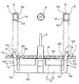
従来、図11乃至図14に示すような計器用ムーブメントの取付構造が知られている(例えば、特許文献1等参照)。 Conventionally, a mounting structure for an instrument movement as shown in FIGS. 11 to 14 is known (see, for example, Patent Document 1).
まず、構成から説明すると、この従来の計器用ムーブメントの取付構造では、車両に搭載される計器内に設けられた計器用回路基板4の裏面側4aに、ムーブメントの筐体を構成するケーシング部材1が、装着されている。
First, in terms of configuration, in this conventional instrument movement mounting structure, a casing member 1 constituting a movement housing is provided on the
このケーシング部材1内には、電力の供給により、回転駆動する図示省略の電動機と、この電動機の回転駆動力を減速する減速ギヤ群と、ファイナルギヤを介して、この回転駆動力を、指針9に伝達する回動軸部材8等とが設けられている。
In the casing member 1, an electric motor (not shown) that is rotationally driven by the supply of electric power, a reduction gear group that decelerates the rotational driving force of the electric motor, and a final gear are used to transmit the rotational driving force to the
また、このケーシング部材1は、拝合により略密閉されるロアケース2及びアッパケース3とを有して主に構成されている。 Further, the casing member 1 is mainly configured to have a lower case 2 and an upper case 3 that are substantially sealed by a marriage.
このうち、アッパケース3側の底面部近傍からは、ロアケース2方向に向けて弾性変形可能な係止アーム部5,5が一対、このアッパケース3と一体にとなるように、前記ロアケース2の側面部2a,2aに沿って延設されている。
Among these, from the vicinity of the bottom surface portion on the upper case 3 side, a pair of
これらの係止アーム部5,5の先端には、各々係止爪部6,6が形成されている。
Locking
また、前記ロアケース2の側面部2a,2aには、前記係止アーム部5,5と対向する位置に、この係止アーム部5,5の弾性変形により、各内側面5a,5aが、当接されるストッパ部7,7が、突設形成されている。
Further, the
次に、この従来の計器用ムーブメントの取付構造の作用について説明する。 Next, the operation of this conventional instrument movement mounting structure will be described.
この従来の計器用ムーブメントの取付構造では、前記計器用回路基板4に開口形成された一対の係止孔4b,4bに、裏面側4aから前記係止アーム部5,5を各々挿通させて、前記係止爪部6,6を係止孔4b,4b周縁に係止することにより、このケーシング部材1が、計器用回路基板4の裏面側4aに装着される。
In this conventional instrument movement mounting structure, the
この際、図12に示すように、前記係止アーム部5,5と対向する位置に、突設形成されている前記ストッパ部7,7に、前記係止アーム部5,5の各内側面5a,5aが、当接されて、一定寸法以上の回動軸部材8方向への移動が阻止されるので、前記係止アーム部5,5の先端部5b,5b間が、傾倒により近接しすぎて、係止孔4b,4b周縁の裏面側に当接してしまう等により、挿入不能となる虞が減少されている。
このように構成された従来の計器用ムーブメントの取付構造では、係止アーム部5,5の係止爪部6,6が、前記係止孔4b,4bに容易に挿通されるように、前記係止孔4b,4bの大きさが大きめに設定されている。
In the conventional instrument movement mounting structure configured as described above, the
このため、図13に示されるように、前記計器用回路基板4に形成された係止孔4b,4bに、前記係止アーム部5,5の係止爪部6,6が係止された状態で、図14に示すように、これらの係止孔4b,4bと、前記係止アーム部5,5との間に間隙が、形成されてしまう。
Therefore, as shown in FIG. 13, the
このような間隙部分からは、ゴミ、布、繊維等のコンタミや、この係止アーム部5又は、前記係止爪部6が、係止孔4b周縁に摺接される際に発生する合成樹脂材料の摩耗粉等の塵芥が、計器内部に侵入してしまう虞があった。
From such a gap portion, contamination such as dust, cloth, fiber, etc., and the synthetic resin generated when the
また、前記係止孔4b,4bの大きさが大きい場合、図14中、二点鎖線で示すように、回動軸部材8と、係止孔4b,4bとの間のスペースA部が、狭くなり、例えば、照明用のLED等を計器用回路基板4上に装着することが困難となってしまうといった問題もあった。
Further, when the size of the
そこで、この発明は、計器内部への塵芥の侵入を防止出来、回路基板上のスペース効率を向上させることが出来る組み付け性が良好な計器用ムーブメントの取付構造を提供することを課題としている。 Accordingly, an object of the present invention is to provide an instrument movement mounting structure that can prevent dust from entering the inside of the instrument and can improve the space efficiency on the circuit board, and has good assemblability.
上記目的を達成するために、請求項1に記載された発明は、回路基板に開口形成された係止孔に、計器用ムーブメントのケーシング部材から一体に延設された弾性変形可能な係止アーム部を挿通させて、該係止アーム部の先端に外側へ向けて形成された係止爪部を前記係止孔周縁に係止することにより、前記計器用ムーブメントのケーシング部材を、前記回路基板に装着する計器用ムーブメントの取付構造であって、前記係止アーム部の前記係止爪部が形成された外側面とは反対側の内側面に、前記係止孔へ前記係止アーム部を挿入する際に、該係止アーム部が内側へ向けて弾性変形される変位角度よりも大きな傾斜角度を有して外側へ傾斜する傾斜面部を形成したことを特徴としている。 In order to achieve the above object, the invention described in claim 1 is an elastically deformable locking arm integrally extended from a casing member of an instrument movement in a locking hole formed in a circuit board. The casing member of the instrument movement is inserted into the circuit board by engaging a locking claw portion formed outwardly at the tip of the locking arm portion with the periphery of the locking hole. a mounting structure of the instrument for movement to be attached to the inner side surface opposite to the outer side surface of the locking claw portion of the locking arm portion is formed, the locking arm to the locking hole when inserting, is characterized in that locking arm portion is inward to form a inclined surface that inclines outward has a greater angle of inclination than the displacement angle is elastically deformed.
また、請求項2に記載されたものは、前記係止アーム部を、前記ケーシング部材の側面部に沿って延設すると共に、該係止アーム部が、弾性変形により当接するストッパ部を前記ケーシング部材の側面部に形成して、前記傾斜面部の傾斜角度を、前記係止孔に、該係止アーム部が挿入される際に、該係止孔の周縁に、該傾斜面部が摺接して、挿入されると共に、前記ストッパ部から該アーム部が離間方向に弾性変形可能に設定されている請求項1記載の計器用ムーブメントの取付構造を特徴としている。 According to a second aspect of the present invention, the locking arm portion extends along the side surface portion of the casing member, and the stopper portion on which the locking arm portion abuts by elastic deformation is provided on the casing. Formed on the side surface of the member, the inclination angle of the inclined surface portion is set so that the inclined surface portion slides on the periphery of the locking hole when the locking arm portion is inserted into the locking hole. The instrument movement mounting structure according to claim 1, wherein the arm portion is inserted into the stopper portion and is elastically deformable in a direction away from the stopper portion.
このように構成された請求項1に記載されたものは、前記係止アーム部の係止爪部が形成された外側面とは反対側の内側面に形成された上記傾斜面部によって、挿入時に前記係止孔周縁に前記傾斜面部が摺接されながら円滑に挿入されるようになる。 The one described in claim 1 thus constructed, by the locking arm locking claw portion above the inclined surface portion formed on the inner side surface opposite to the outer side surface formed of, upon insertion The inclined surface portion is smoothly inserted while being in sliding contact with the periphery of the locking hole.
このため、該係止孔を比較的小さく設定しても、組み付け性を良好なものとすることが出来るので、該係止孔に、前記係止アーム部の係止爪部が係止された状態で、該係止孔と、前記係止アーム部との間に形成される間隙量を減少させることが出来、計器内部への塵芥の侵入を防止出来る。 For this reason, even if the locking hole is set to be relatively small, the assemblability can be improved, so that the locking claw portion of the locking arm portion is locked in the locking hole. In this state, the amount of the gap formed between the locking hole and the locking arm portion can be reduced, and dust can be prevented from entering the instrument.
また、請求項2に記載されたものは、前記傾斜面部の傾斜角度が、前記係止孔に、該係止アーム部が挿入される際に、該係止孔の周縁に、該傾斜面部が摺接して、挿入されると共に、前記ストッパ部から該アーム部が離間方向に弾性変形可能に設定されている。 Further, according to a second aspect of the present invention, the inclination angle of the inclined surface portion is such that when the locking arm portion is inserted into the locking hole, the inclined surface portion is arranged at the periphery of the locking hole. The arm portion is set so as to be elastically deformable in the separating direction from the stopper portion while being inserted in sliding contact.
このため、例えば、機械組や、或いは、作業者による手組で、組み立て作業を行う際に、前記係止アーム部を、弾性変形させて、前記ストッパ部に当接させるように把持しても、挿入時に、前記係止孔の周縁に、該傾斜面部が摺接して、該ストッパ部から該アーム部が離間方向に弾性変形しながら挿入可能である。 For this reason, for example, when the assembly work is performed by a machine set or a hand set by an operator, the locking arm portion may be elastically deformed and held so as to come into contact with the stopper portion. At the time of insertion, the inclined surface portion can be slidably contacted with the peripheral edge of the locking hole, and the arm portion can be inserted from the stopper portion while being elastically deformed in the separation direction.
従って、機械組や、或いは、作業者による手組の何れの方法で、同様に組み付けることが出来、更に、組み付け性を良好なものとすることができる。 Therefore, it can be similarly assembled by any method of a machine assembly or a manual assembly by an operator, and the assembly property can be improved.
次に、図面に基づいて、この発明を実施するための最良の実施の形態の計器用ムーブメントの取付構造について説明する。なお、前記従来例と同一乃至均等な部分については同一符号を付して説明する。 Next, an instrument movement mounting structure according to the best mode for carrying out the present invention will be described with reference to the drawings. In addition, the same code | symbol is attached | subjected and demonstrated about the same or equivalent part as the said prior art example.
図1乃至図10は、この発明の最良の実施の形態の計器用ムーブメントの取付構造を示すものである。 1 to 10 show a mounting structure for an instrument movement according to the preferred embodiment of the present invention.
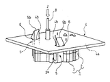
まず、全体の構成について、図2乃至図4を用いて説明すると、この実施の形態の計器用ムーブメント10は、車両に搭載される計器としてのコンビネーションメータ17内に設けられた計器用回路基板4の裏面側に、装着されるものである。
First, the overall configuration will be described with reference to FIGS. 2 to 4. The
このコンビネーションメータ17は、主に、ロアハウジング18及びアッパハウジング19によって構成される筐体20内に、各種指針9等の表示部が設けられた文字盤21が配設されて構成されている。
The
この筐体20の前面側には、図4に示すように、透明合成樹脂製のフロントカバー部材22が、前記文字盤21を覆うように、装着されると共に、裏面側には、前記計器用ムーブメント10が、固着される計器用回路基板4が装着されている。
As shown in FIG. 4, a
この計器用ムーブメント10は、拝合により略密閉されるロアケース11及びアッパケース12とからなる合成樹脂製のケーシング部材13を有している。
The
このケーシング部材13内には、図示省略のコア部材と、電力の供給により、コア部材との間で回転駆動力を発生させる電動機と、この電動機の回転駆動力を減速する減速ギヤ…群とが設けられている。
In the
また、このケーシング部材13には、図4に示すように、指針9を軸支する回動軸部材8が設けられていて、前記減速ギヤと噛み合うファイナルギヤ部材8aが、一体に固着されている。
Further, as shown in FIG. 4, the
そして、前記電動機の回転駆動力が、これらの減速ギヤ群及びファイナルギヤ部材8aを介して、この回動軸部材8に伝達されて、前記指針9を回動させるように構成されている。
The rotational driving force of the electric motor is transmitted to the rotating
また、前記ケーシング部材13のうち、アッパケース12の底面部12a側縁からは、弾性変形可能な合成樹脂製の係止アーム部14,14が、ケーシング部材13から一体となるように、前記計器用回路基板4の方向に向けて、付根側屈曲部14a,14aから、約90度屈曲されて延設されている。
In addition, from the
これらの係止アーム部14,14の先端には、係止爪部15,15が、お互いに外側に向けて突設形成されている。
At the tips of these
そして、前記計器用回路基板4に開口形成された一対の係止孔24b,24bに、裏面側4aから前記係止アーム部14,14を各々挿通させて、前記係止爪部15,15が、係止孔24b,24b周縁に係止されることにより、このケーシング部材13が、計器用回路基板4の裏面側4aに装着されるように構成されている。
Then, the
この実施の形態の計器用ムーブメントの取付構造では、図5に示すように、前記係止アーム部14,14の係止爪部15,15が形成された外側面14b,14bとは反対側の内側面14c,14cに、前記係止孔24b,24bへ係止アーム部14,14を挿入する際に、係止アーム部14,14が内側へ向けて弾性変形される変位角度α2(図8参照)よりも大きな傾斜角度α1(図6参照)を有して外側へ傾斜する傾斜面部14d,14dが各々形成されている。
In the instrument movement mounting structure of this embodiment, as shown in FIG. 5, the
また、この実施の形態の計器用回路基板4の係止孔24b,24bは、図7及び図9中二点鎖線で、比較して示す従来の係止孔4b,4bよりも小さくなるように設定されている。
Also, the
次に、この実施の形態の計器用ムーブメントの取付構造の作用効果について説明する。 Next, the function and effect of the instrument movement mounting structure of this embodiment will be described.
このように構成された実施の形態の計器用ムーブメントの取付構造では、前記計器用回路基板4の裏面側4aに、前記計器用ムーブメント10を装着する際、図9に示すように、前記係止アーム部14の前記係止爪部15が形成された外側面14bとは反対側の内側面14cに形成された傾斜面部14dによって、挿入時に前記係止孔24bの内周縁24cに、この傾斜面部14dが摺接されながらガイドされることにより、円滑に挿入されるようになる。
In the instrument movement mounting structure of the embodiment configured as described above, when the
このため、これらの係止孔24b,24bを比較的小さく設定しても、組み付け性を良好なものとすることが出来る。
For this reason, even if these locking
従って、図10に示すように、これらの係止孔24b,24bに、前記係止アーム部14,14の係止爪部15,15が係止された状態で、これらの係止孔24b,24bと、前記係止アーム部14,14との間に形成される間隙量を減少させることが出来、計器内部への塵芥の侵入を防止出来る。
Accordingly, as shown in FIG. 10, in the state where the locking
また、図10中に示すように、回動軸部材8と、係止孔24b,24bとの間の計器用回路基板4上のスペースを広く設定することが可能となり、例えば、照明用のLED等を、この回動軸部材8と、係止孔24b,24bとの間の計器用回路基板4上に装着することが容易である。
Further, as shown in FIG. 10, it is possible to set a wide space on the
従って、回路基板上のスペース効率を向上させることが出来、レイアウトの自由度を向上させることが出来る。 Therefore, the space efficiency on the circuit board can be improved, and the degree of freedom in layout can be improved.
図1乃至図10は、この発明の最良の実施の形態の実施例1の計器用ムーブメントの取付構造を示すものである。 1 to 10 show a mounting structure for an instrument movement according to Example 1 of the best mode of the present invention.
なお、前記実施の形態と同一乃至均等な部分については、前記実施の形態と同一符号を付して説明する。 Note that portions that are the same as or equivalent to those in the above-described embodiment are described with the same reference numerals as those in the above-described embodiment.
まず、この実施例1の構成を説明すると、この実施例1の計器用ムーブメントの取付構造では、図5に示すように、前記係止アーム部14,14が、前記ケーシング部材13の側面部13a,13aに沿って延設されている。
First, the configuration of the first embodiment will be described. In the instrument movement mounting structure of the first embodiment, as shown in FIG. 5, the locking
このケーシング部材13の側面部13a,13aには、前記係止アーム部14,14の内側面14c,14cが、弾性変形により当接するストッパ部13b,13bが、形成されている。
そして、図6に示すように、前記傾斜面部14dの前記係止アーム部14内側面14cに対する傾斜角度α1を、図8に示すように、前記係止アーム部14,14の弾性変形により、前記内側面14c,14cが、前記ストッパ部13b,13bに当接するまでの鉛直からの変位角度α2よりも大きく(α1>α2)なるように設定されている。
Then, as shown in FIG. 6, the inclination angle α1 of the
このため、弾性変形によりストッパ部13b,13bに前記係止アーム部14の内側面14cが当接して停止した状態で、鉛直よりも外側に拡開する所定の正の角度α3(この実施例1では、約0.5度〜30度)が得られるように構成されている。
Therefore, the
また、図7に示すように、前記係止アーム部14,14の弾性変形によって、前記内側面14c,14cが、前記ストッパ部13b,13bに当接されている状態で、係止アーム部14,14の先端部14e,14eが、前記係止孔24b,24bの各内周縁24c,24cから、一定距離d1,d1を置いて離間されることにより、係止アーム部14,14の先端部14e,14eが、計器用回路基板4の裏面側4aに当接等すること無く、容易に前記係止孔24b,24b内に挿入可能となるように構成されている。
Further, as shown in FIG. 7, I by the elastic deformation of the locking
このように、この実施例1では、鉛直よりも外側に拡開する所定の正角度α3が、得られるので、図9に示すように、前記係止孔24b,24bに、係止アーム部14,14が挿入される際に、係止孔24b,24bの各内周縁24c,24cに、これらの傾斜面部14d,14dが摺接されて、挿入可能に傾斜されるように構成されている。
As described above, in the first embodiment, the predetermined positive angle α3 that expands outward from the vertical direction is obtained. Therefore, as shown in FIG. 9, the locking
また、この各内周縁24c,24cに、これらの傾斜面部14d,14dが摺接される反力で、前記ストッパ部13b,13bから、これらの係止アーム部14,14が、離間する方向に弾性変形可能に設定されている。
In addition, the reaction force by which the
更に、この実施例1では、図10に示すように、前記係止アーム部14,14の内側面14c,14cと、前記傾斜面部14d,14dとを接続する傾斜開始点14f,14fが、設けられている。
Further, in the first embodiment, as shown in FIG. 10, there are provided inclination start points 14f and 14f for connecting the inner side surfaces 14c and 14c of the locking
この傾斜開始点14f,14fは、前記係止爪部15,15が、係止孔24b,24bの周縁部に係止された状態で、これらの係止孔24b,24b内に挿入されて、位置するように設定されていて、上面視で、これらの係止アーム部14,14及び一体に設けられた係止爪部15,15によって、略係止孔24b,24bの全面積が、僅かな隙間を残して、覆われるように構成されている。
The
次に、この実施例1の計器用ムーブメントの取付構造の作用効果について説明する。 Next, the function and effect of the instrument movement mounting structure of the first embodiment will be described.
この実施例1の計器用ムーブメントの取付構造では、前記実施の形態の作用効果に加えて、更に、前記計器用回路基板4の裏面側4aに、前記計器用ムーブメント10を装着する際、図7及び図8に示すように、前記係止アーム部14,14の外側面14a,14aを、外側から機械組や、或いは、作業者による手組を行うため把持して、前記付根側屈曲部14a,14aを中心として、前記係止アーム部14,14を弾性変形させると、前記内側面14c,14cに設けられた傾斜開始点14f,14fが、前記ケーシング部材13の側面部13a,13aに形成されたストッパ部13b,13bに当接して、内倒方向への移動を停止させる。
In the instrument movement mounting structure of Example 1, in addition to the effects of the above embodiment, when the
また、図7に示すように、前記前記係止アーム部14,14の弾性変形により、前記内側面14c,14cが、前記ストッパ部13b,13bに当接されている状態で、係止アーム部14,14の先端部14e,14eは、前記係止孔24b,24bの各内周縁24c,24cから、一定距離d1,d1を置いて離間されている。
In addition, as shown in FIG. 7, the locking
このため、図7に示すように、まず、前記先端部14e,14eが、係止孔24b,24bの裏面側4aの周縁に当接することなく、これらの係止孔24b,24b内に挿入されると共に、前記係止爪部15,15が形成された外側面14b,14bに対して、反対側の内側面14c,14cに形成された傾斜面部14d,14dが、前記係止孔24b,24bの内周縁24c,24cに、摺接されながら、ガイドされることにより、円滑に挿入される。
Therefore, as shown in FIG. 7, first, the
よって、これらの係止孔24b,24bを比較的小さく設定しても、組み付け性を良好なものとすることが出来る。
Therefore, even if these locking
また、この実施例1では、前記傾斜面部14d,14dの傾斜角度α1が、前記係止孔24b,24bに、これらの係止アーム部14,14が挿入される際に、図9に示すように、前記内周縁24c,24cに、前記傾斜面部14d,14dが摺接されながら、挿入されると、前記ストッパ部13b,13から、合成樹脂製の係止アーム部14,14が、離間する方向に向けて弾性変形されて、拡開し、円滑な挿入が妨げられることがない。
In the first embodiment, the inclination angle α1 of the
このため、例えば、機械組や、或いは、作業者による手組で、組み立て作業を行う際に、前記係止アーム部14,14を、弾性変形させて、前記ストッパ部13b,13bに当接させるように、外側面14b,14b側から把持したままでも、挿入時に、前記係止孔24b,24bの内周縁24c,24cに、前記傾斜面部14d,14dに摺接することで、離間方向に弾性変形しながら、係止アーム部14,14間が拡開して挿入可能である。
For this reason, for example, when the assembly work is performed by a machine set or a hand set by an operator, the locking
従って、機械組や、或いは、作業者による手組の何れの方法で、同様に組み付けることが出来、更に、組み付け性を良好なものとすることができる。 Therefore, it can be similarly assembled by any method of a machine assembly or a manual assembly by an operator, and the assembly property can be improved.
このように、これらの係止孔24b,24bに、前記係止アーム部14,14の係止爪部15,15が係止された状態では、図10に示されるように、これらの係止孔24b,24bと、前記係止アーム部14,14との間に形成される間隙量を減少させることが出来、計器内部への塵芥の侵入を防止出来る。
Thus, in the state where the locking
他の構成及び作用効果については、前記実施の形態と同一乃至均等であるので、説明を省略する。 Other configurations and operational effects are the same as or equivalent to those of the above-described embodiment, and thus description thereof is omitted.
以上、図面を参照して、本発明の実施の形態を詳述してきたが、具体的な構成は、この実施の形態に限らず、本発明の要旨を逸脱しない程度の設計的変更は、本発明に含まれる。 The embodiment of the present invention has been described in detail above with reference to the drawings. However, the specific configuration is not limited to this embodiment, and design changes that do not depart from the gist of the present invention are not limited to this embodiment. Included in the invention.
即ち、前記実施例1では、前記傾斜面部14dの前記係止アーム部14の内側面14cに対する傾斜角度α1を、図8に示すように、前記係止アーム部14,14の弾性変形により、前記内側面14c,14cが、前記ストッパ部13b,13bに当接するまでの鉛直からの変位角度α2よりも大きく(α1>α2)なるように設定しているが、この傾斜面は湾曲、若しくは多段となっていてもよい。
That is, in the first embodiment, the inclination angle α1 of the
10 計器用ムーブメント
11 ロアケース
12 アッパケース
13 ケーシング部材
13a 側面部
13b ストッパ部
14 係止アーム部
14b 外側面
14c 内側面
14d 傾斜面部
17 コンビネーションメータ(計器)
24b 係止孔
24c 内周縁
DESCRIPTION OF
Claims (2)
前記係止アーム部の前記係止爪部が形成された外側面とは反対側の内側面に、前記係止孔へ前記係止アーム部を挿入する際に、該係止アーム部が内側へ向けて弾性変形される変位角度よりも大きな傾斜角度を有して外側へ傾斜する傾斜面部を形成したことを特徴とする計器用ムーブメントの取付構造。 An elastically deformable locking arm portion integrally extended from the casing member of the instrument movement is inserted into the locking hole formed in the circuit board, and the outer end of the locking arm portion is directed outward. An instrument movement mounting structure for mounting the casing member of the instrument movement to the circuit board by locking the formed locking claw portion to the periphery of the locking hole ,
On the inner side surface of the engagement side opposite to the outer side surface of the locking claw portion is formed in the locking arm, when inserting the locking arm to the locking hole, the locking arm portion inwardly mounting structure of instrument movement, characterized in that the formation of the inclined surface inclined outward with a greater angle of inclination than the displacement angle which is elastically deformed toward.
Priority Applications (1)
| Application Number | Priority Date | Filing Date | Title |
|---|---|---|---|
| JP2006148435A JP4912751B2 (en) | 2006-05-29 | 2006-05-29 | Mounting structure for instrument movement |
Applications Claiming Priority (1)
| Application Number | Priority Date | Filing Date | Title |
|---|---|---|---|
| JP2006148435A JP4912751B2 (en) | 2006-05-29 | 2006-05-29 | Mounting structure for instrument movement |
Publications (2)
| Publication Number | Publication Date |
|---|---|
| JP2007316015A JP2007316015A (en) | 2007-12-06 |
| JP4912751B2 true JP4912751B2 (en) | 2012-04-11 |
Family
ID=38849991
Family Applications (1)
| Application Number | Title | Priority Date | Filing Date |
|---|---|---|---|
| JP2006148435A Expired - Fee Related JP4912751B2 (en) | 2006-05-29 | 2006-05-29 | Mounting structure for instrument movement |
Country Status (1)
| Country | Link |
|---|---|
| JP (1) | JP4912751B2 (en) |
Family Cites Families (3)
| Publication number | Priority date | Publication date | Assignee | Title |
|---|---|---|---|---|
| JP2750148B2 (en) * | 1988-04-20 | 1998-05-13 | 三共株式会社 | Propagation method of Croton plant seedlings |
| JP4027239B2 (en) * | 2003-02-12 | 2007-12-26 | カルソニックカンセイ株式会社 | Motor mounting structure |
| JP4508685B2 (en) * | 2004-03-08 | 2010-07-21 | 矢崎総業株式会社 | Motor support structure |
-
2006
- 2006-05-29 JP JP2006148435A patent/JP4912751B2/en not_active Expired - Fee Related
Also Published As
| Publication number | Publication date |
|---|---|
| JP2007316015A (en) | 2007-12-06 |
Similar Documents
| Publication | Publication Date | Title |
|---|---|---|
| JP4922390B2 (en) | Window glass wiper drive device | |
| US20150336529A1 (en) | Steering Wheel Unit | |
| JP2005083321A (en) | Mounting structure of cooling fan device in heat exchanger unit | |
| JP5271752B2 (en) | Rotating connector mounting structure | |
| JP4912751B2 (en) | Mounting structure for instrument movement | |
| WO2015083334A1 (en) | Operation device | |
| JP4735489B2 (en) | FIXED STRUCTURE AND VEHICLE INSTRUMENT HAVING THE SAME | |
| JP5297680B2 (en) | Instrument unit | |
| CN103702857B (en) | Dashboard and method for assembling dashboard | |
| JP6063165B2 (en) | Meter device | |
| CN118401353A (en) | Joint robot | |
| JP4908050B2 (en) | Mounting structure for instrument movement | |
| JP5041292B2 (en) | Display device | |
| JP4508685B2 (en) | Motor support structure | |
| JP4511864B2 (en) | Instrument | |
| JP4844810B2 (en) | Assembly structure in instrument equipment | |
| JP6187206B2 (en) | Operating device | |
| CN217159776U (en) | A actuating mechanism fixing device for cell phone stand telescopic machanism | |
| EP3121053A2 (en) | Cluster illumination by piezoelectrical material | |
| JP4479661B2 (en) | Knob | |
| JP6887118B2 (en) | Electric tool | |
| JP2006300645A (en) | Measuring instrument for vehicle | |
| WO2019150642A1 (en) | Vehicle key | |
| EP1498329A3 (en) | Support for fixing windshield wiper drive devices | |
| JP5756997B2 (en) | Shift lever device |
Legal Events
| Date | Code | Title | Description |
|---|---|---|---|
| A621 | Written request for application examination |
Free format text: JAPANESE INTERMEDIATE CODE: A621 Effective date: 20090424 |
|
| A131 | Notification of reasons for refusal |
Free format text: JAPANESE INTERMEDIATE CODE: A131 Effective date: 20111108 |
|
| A521 | Written amendment |
Free format text: JAPANESE INTERMEDIATE CODE: A523 Effective date: 20111205 |
|
| TRDD | Decision of grant or rejection written | ||
| A01 | Written decision to grant a patent or to grant a registration (utility model) |
Free format text: JAPANESE INTERMEDIATE CODE: A01 Effective date: 20120117 |
|
| A01 | Written decision to grant a patent or to grant a registration (utility model) |
Free format text: JAPANESE INTERMEDIATE CODE: A01 |
|
| A61 | First payment of annual fees (during grant procedure) |
Free format text: JAPANESE INTERMEDIATE CODE: A61 Effective date: 20120118 |
|
| R150 | Certificate of patent or registration of utility model |
Free format text: JAPANESE INTERMEDIATE CODE: R150 |
|
| FPAY | Renewal fee payment (event date is renewal date of database) |
Free format text: PAYMENT UNTIL: 20150127 Year of fee payment: 3 |
|
| R250 | Receipt of annual fees |
Free format text: JAPANESE INTERMEDIATE CODE: R250 |
|
| R250 | Receipt of annual fees |
Free format text: JAPANESE INTERMEDIATE CODE: R250 |
|
| LAPS | Cancellation because of no payment of annual fees |