JP4911368B2 - Bolts, nut caps, and confirmation methods for forgetting bolts and nuts - Google Patents
Bolts, nut caps, and confirmation methods for forgetting bolts and nuts Download PDFInfo
- Publication number
- JP4911368B2 JP4911368B2 JP2008106362A JP2008106362A JP4911368B2 JP 4911368 B2 JP4911368 B2 JP 4911368B2 JP 2008106362 A JP2008106362 A JP 2008106362A JP 2008106362 A JP2008106362 A JP 2008106362A JP 4911368 B2 JP4911368 B2 JP 4911368B2
- Authority
- JP
- Japan
- Prior art keywords
- bolt
- nut
- nut cap
- bolts
- cover portion
- Prior art date
- Legal status (The legal status is an assumption and is not a legal conclusion. Google has not performed a legal analysis and makes no representation as to the accuracy of the status listed.)
- Expired - Fee Related
Links
Images
Landscapes
- Bolts, Nuts, And Washers (AREA)
Description
この発明は、ボルト、又はナットの締め忘れを防止するためのボルト、ナットキャップ、及び、ボルト、ナット締め忘れ確認方法に関する。 The present invention relates to a bolt, a nut cap, and a bolt and nut tightening confirmation method for preventing a bolt or nut from being forgotten to be tightened.
従来、住宅における母屋、垂木、棟木等から構成される小屋組を始めとして、各部材同士を連結する際には、ボルトやナットが多く使用されており、これらの締め忘れが発生する可能性があった。そのため、ボルト、ナット締め忘れ検査用突き棒にて、これらの打撃確認を行ったり、ボルト、ナットを締めた後にマジック等でマーキングを行うことにより、当該ボルト、ナットの締め忘れを防止している。また、その他にも、以下のような包被ナットを用いてこれらの締め忘れを防止している。 Conventionally, many bolts and nuts are used when connecting each member, including a hut assembly composed of a purlin, rafters, purlins, etc. in a house, and these may be forgotten to be tightened. there were. For this reason, these bolts and nuts are forgotten to be tightened by checking the impact with a test stick for forgetting bolts or nuts, or marking with a magic after tightening the bolts and nuts. . In addition, the following nuts are used to prevent these forgetting to tighten.
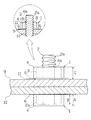
この包被ナット101は、図7に示すように、ナット102の下にバネ座金103を介在させ、当該バネ座金103と前記ナット102を合成樹脂フィルムの包被材104により前記バネ座金103の下方にまで巻き込むように包被する。これにより、ナット102の締め付けによってバネ座金103が変形して、当該包被材104に設けられたミシン目105に従って当該包被材104が破れ、ナット102が締め付けられたか否かを目視で判断することができる。(例えば、特許文献1)。また、その他にも、塗料を封入したフィルムバッグをナットの座金の下方に介在させておき、該ナットを本締めして該フィルムバッグを破裂させ、塗料を吐出させることによりナットの締め忘れを目視で確認することができるナットも考案されている(例えば、特許文献2)
As shown in FIG. 7, the
しかし、上述の検査用突き棒にてボルト、ナットの締め忘れを確認する場合には、住宅の施工に使用されるボルト、ナットの数が非常に多いので、すべてを検査するのに長時間を要していた。また、小屋組等の場所では、作業者が脚立を使用する等の高所作業を行う必要があり、安全性の面でも問題があった。そして、上述のマジック等でマーキングを行う方法や、包被ナットを使用する場合には、何らかの理由でボルト、ナットを緩める必要が生じた際には、これらの効力は失われるので再びボルト、ナットの締め忘れが生じる可能性がある。さらに、小屋組等の場所では作業者からボルト、ナットまでの距離が遠く視認しずらいという問題もあった。 However, when confirming that the bolts and nuts have been forgotten to be tightened with the above-mentioned inspection thruster, the number of bolts and nuts used in the construction of the house is very large, so it takes a long time to inspect everything. It was necessary. In addition, in places such as a cabin set, it is necessary for the worker to perform high-level work such as using a stepladder, and there is a problem in terms of safety. And when marking with the above-mentioned magic, etc., or when using a covered nut, if it becomes necessary to loosen the bolt or nut for any reason, these effects will be lost, so the bolt and nut again. There is a possibility of forgetting to tighten. Furthermore, there is a problem that it is difficult to visually recognize the distance from the worker to the bolt and the nut in a place such as a roof set.
この発明は上記のような種々の課題を解決することを目的としてなされたものであって、ボルトの頭部、又はナットへの取付けが容易であり、また、目視により短時間でボルト、ナットの締め忘れを確認することができ、さらに、一旦締めた当該ボルト、ナットを再び緩めたとしてもこれらの締め忘れが生じることのないボルト、ナットキャップ、及び、ボルト、ナット締め忘れ確認方法に関する。 The present invention has been made for the purpose of solving the various problems as described above, and can be easily attached to the head of a bolt or a nut. Further, the present invention relates to a bolt, a nut cap, and a bolt and nut forgetting confirmation method that can confirm forgetting tightening and that will not cause forgetting to tighten even if the bolts and nuts once tightened are loosened again.
上記目的を達成するために、請求項1記載のボルト、ナットキャップは、ボルトの頭部、又はナットに取付けられこれらの締め忘れを防止するボルト、ナットキャップにおいて、前記ボルトの頭部、又は前記ナットを覆う可撓性部材からなる略楕円柱状のカバー部と、該カバー部の略楕円形の上面部に前記ボルトのネジ部を挿通可能に形成された略円形の挿通孔と、前記上面部の長軸方向に相対向して前記挿通孔の内縁部から外周方向に向かって形成された内側切込みと、前記カバー部の下方縁部から外側方向に略円形となるように設けられた鍔部と、前記内側切込みと略垂直方向に相対向して該鍔部の外縁部から内側方向に形成された外側切込みと、を有しハット型に形成されたことを特徴としている。
In order to achieve the above object, the bolt and nut cap according to
請求項2記載のボルト、ナットキャップは、請求項1記載のボルト、ナットキャップに色彩が施されたことを特徴としている。
The bolt and nut cap according to
請求項3記載のボルト、ナットキャップは、請求項1記載のボルト、ナットキャップに蛍光塗料が塗布、又は含有されたことを特徴としている。
The bolt and nut cap according to
請求項4記載のボルト、ナットキャップは、請求項1記載のボルト、ナットキャップに蓄光塗料が塗布、又は含有されたことを特徴としている。
The bolt and nut cap according to
請求項5記載のボルト、ナット締め忘れ確認方法は、ボルト、又はナットを締めた後に、請求項1乃至4記載のボルト、ナットキャップをその略楕円柱状の前記カバー部の長軸方向から挟持し該カバー部の短軸方向の幅を広げて前記ボルトの頭部、又は前記ナットに被せて取付けることを特徴としている。 According to a fifth aspect of the present invention, the bolt or nut tightening confirmation method includes clamping the bolt or nut cap according to any one of the first to fourth aspects from the major axis direction of the substantially elliptical columnar cover portion after tightening the bolt or nut. It is characterized in that the width of the cover portion in the minor axis direction is widened and the cover portion is attached to the bolt head or the nut.
請求項1記載のボルト、ナットキャップによれば、略楕円柱状に形成されたカバー部の上面部に形成された挿通孔において、その内縁部から外周方向に向かって該上面部の長軸方向に相対向して形成された内側切込みと、該カバー部の下端縁部から外側方向に形成された鍔部において、内側切込みと略垂直方向に相対向して該鍔部の外縁部から内側方向に形成された外側切込みと、を有している。これにより、カバー部の長軸方向から挟持すれば内側切込みが開き、該カバー部の長軸方向の長さが短くなると共に、その短軸方向の幅が広がる。これに従い、鍔部にも歪が生じるが、これを吸収するように当該鍔部に形成された外側切込みも開く。従って、作業者が容易にボルトの頭部、又はナットに、本発明に係るボルト、ナットキャップを取付けることができる。
According to the bolt and nut cap according to
さらに、前述のようにボルトの頭部、又はナットにボルト、ナットキャップを取付けた後は、カバー部の短軸方向の幅は、その復元力により元の形状に戻ろうとして当該ボルトの頭部、又はナットを挟持するため、一旦取付けられた当該ボルト、ナットキャップが容易に外れることがない。さらに、挿通孔にボルトのネジ部を挿通して、ナットにボルト、ナットキャップを取付けた場合には、内側切込みと挿通孔の内縁部が形成する角部が当該ネジ部のネジ溝に係止されるので、該ボルトからボルト、ナットキャップが容易に外れることがない。 Furthermore, after attaching the bolt and nut cap to the head of the bolt or the nut as described above, the width of the cover portion in the minor axis direction tries to return to the original shape by its restoring force. Or, since the nut is clamped, the bolt and nut cap once attached are not easily detached. Furthermore, when the screw part of the bolt is inserted into the insertion hole, and the bolt and nut cap are attached to the nut, the corner formed by the inner notch and the inner edge of the insertion hole is locked in the screw groove of the screw part. Therefore, the bolt and the nut cap are not easily detached from the bolt.
そして、ボルト、ナットを締めた後、これらにボルト、ナットキャップを取付けることで、ボルト、ナットが締められているか否かを目視で確認することができるので作業が効率的である。さらに、何らかの理由でボルト、ナットを緩める必要があった場合には、ボルトの頭部、又はナットに被せられるカバー部が楕円柱状に形成されており、さらに、これらとカバー部の間には隙間を有しているので、ボルト、ナットキャップをボルトの頭部、又は、ナットに被せた状態では、レンチ等でこれらを緩めることができない。従って、何らかの理由でボルト、ナットを緩める際には、ボルト、ナットキャップを一旦取外す必要があり、これを再び締め忘れたとしても当該ボルト、ナットにはボルト、ナットキャップが取り付けられていない状態なので、この締め忘れを見逃すことがない。そして、ボルト、ナットを再び締めた後に、ボルト、ナットキャップを再び取付ければ、これが締められているか否かを目視で確認することができるので作業が効率的である。 And after tightening a bolt and a nut, by attaching a bolt and a nut cap to these, since it can be visually confirmed whether the bolt and a nut are tightened, work is efficient. In addition, when it is necessary to loosen the bolt or nut for some reason, the head of the bolt or the cover portion covering the nut is formed in an elliptical column shape, and there is a gap between these and the cover portion. Therefore, when the bolt and nut cap are put on the bolt head or nut, they cannot be loosened with a wrench or the like. Therefore, when loosening bolts and nuts for some reason, it is necessary to remove the bolts and nut caps. Even if you forget to tighten them again, the bolts and nut caps are not attached to the bolts and nuts. , Never miss this forgotten. Then, after the bolts and nuts are tightened again, if the bolts and nut caps are reattached, it is possible to visually confirm whether or not the bolts and nut caps are tightened, so that the operation is efficient.
また、カバー部の下方縁部から外側方向に略円形の鍔部が形成されている。これにより、母屋、垂木、棟木等から構成される小屋組等の高い位置で使用されるボルト、ナットに、ボルト、ナットキャップを取付けた際にも、視認性がよいのでこれを見落とすことがないという利点がある。 Moreover, the substantially circular collar part is formed in the outer side direction from the lower edge part of the cover part. As a result, even when bolts and nut caps are attached to bolts and nuts that are used in high positions such as huts composed of purlins, rafters, purlins, etc., they will not be overlooked because the visibility is good. There is an advantage.
また、略楕円柱状のカバー部の略楕円形の上面部には、ボルトのねじ部を挿通可能な略円形の挿通孔が形成されている。これにより、ボルトのネジ部がナットから出ていたとしても、当該ネジ部を挿通孔に挿入すれば、容易に当該ナットにボルト、ナットキャップを取付けることができる。 In addition, a substantially circular insertion hole into which the screw portion of the bolt can be inserted is formed in the substantially elliptical upper surface portion of the substantially elliptical columnar cover portion. Thereby, even if the screw portion of the bolt protrudes from the nut, the bolt and the nut cap can be easily attached to the nut by inserting the screw portion into the insertion hole.
請求項2記載のボルト、ナットキャップによれば、請求項1記載のボルト、ナットキャップに色彩が施されている。これにより、ボルト、ナットを締めた後、これらにボルト、ナットキャップを取付けた際の視認性が向上する。
According to the bolt and nut cap described in
請求項3記載のボルト、ナットキャップによれば、請求項1記載のボルト、ナットキャップに蛍光塗料が塗布、又は含有されている。これにより、例えば夕方になって周囲の照度が低くなったとしても、僅かな照明でも目立ちやすくなり、ボルト、ナットを締めた後、これらにボルト、ナットキャップを取付けた際の視認性がより向上する。
According to the bolt and nut cap of
請求項4記載のボルト、ナットキャップによれば、請求項1記載のボルト、ナットキャップに蓄光塗料が塗布、又は含有されている。これにより、太陽が沈みかける等作業現場の照度が低下した場合であっても、太陽光等を吸収したボルト、ナットキャップが自発的に発光するのでボルト、ナットを締めた後、これらにボルト、ナットキャップを取付けた際の視認性が向上する。
According to the bolt and nut cap described in
請求項5記載のボルト、ナット締め忘れ確認方法によれば、ボルト、又はナットを締めた後に、請求項1乃至4記載のボルト、ナットキャップをその略楕円柱状の前記カバー部の長軸方向から挟持し該カバー部の短軸方向の幅を広げて前記ボルトの頭部、又は前記ナットに被せて取付けている。これにより、容易にボルト、ナットキャップを取付けることができると共に、これが容易に脱離することがない。そして、ボルト、ナットを締めた後、これらにボルト、ナットキャップを取付けることで、ボルト、ナットが締められているか否かを目視で確認することができるので作業が効率的であり、高所作業が発生することがなく安全性も確保することができる。
According to the bolt and nut tightening confirmation method according to
さらに、何らかの理由でボルト、ナットを緩める必要があった場合には、ボルトの頭部、又はナットに被せられるカバー部が楕円柱状に形成されており、さらに、これらとカバー部の間には隙間を有しているので、ボルト、ナットキャップをボルトの頭部、又は、ナットに被せた状態では、レンチ等でこれらを緩めることができない。従って、何らかの理由でボルト、ナットを緩める際には、ボルト、ナットキャップを一旦取外す必要があり、これを再び締め忘れたとしても当該ボルト、ナットにはボルト、ナットキャップが取り付けられていない状態なので、この締め忘れを見逃すことがない。そして、ボルト、ナットを再び締めた後に、ボルト、ナットキャップを再び取付ければ、これが締められているか否かを目視で確認することができるので作業が効率的である。 In addition, when it is necessary to loosen the bolt or nut for some reason, the head of the bolt or the cover portion covering the nut is formed in an elliptical column shape, and there is a gap between these and the cover portion. Therefore, when the bolt and nut cap are put on the bolt head or nut, they cannot be loosened with a wrench or the like. Therefore, when loosening bolts and nuts for some reason, it is necessary to remove the bolts and nut caps. Even if you forget to tighten them again, the bolts and nut caps are not attached to the bolts and nuts. , Never miss this forgotten. Then, after the bolts and nuts are tightened again, if the bolts and nut caps are reattached, it is possible to visually confirm whether or not the bolts and nut caps are tightened, so that the operation is efficient.
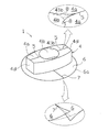
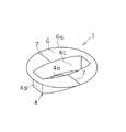
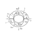
この発明におけるボルト、ナットキャップの最良の実施形態について、以下に説明する。本発明に係るボルト、ナットキャップ1は、図1、図2、図6に示すように、ハット型に形成されると共に、ボルト2の頭部2a、又はナット3を覆う可撓性部材からなる略楕円柱状のカバー部4と、該カバー部4の略楕円形の上面部4aに前記ボルト2のネジ部2bを挿通可能に形成された略円形の挿通孔4bと、前記上面部4aの長軸方向に相対向して前記挿通孔4bの内縁部41bから外周方向に向かって形成された内側切込み5と、前記カバー部4の下方縁部から外側方向に略円形となるように設けられた鍔部6と、前記内側切込み5と略垂直方向に相対向して該鍔部6の外縁部6aから内側方向に形成された外側切込み7と、を有している。
The best embodiment of the bolt and nut cap in the present invention will be described below. The bolt and
前記ボルト、ナットキャップ1は、ポリエチレンやポリプロピレン等の可撓性を有し、安価で成形加工が容易な汎用の合成樹脂材料を好適に使用することができる。また、ボルト、ナットキャップ1を製造する際には、例えばポリプロピレンのシート材料をプレス成型することにより製造することができる。そして、前記シート材料を予め、赤、青、黄等の作業者が視認しやすいような色彩を施しておくことができる。また、紫外線や可視光線等の照射により蛍光を放出するような蛍光塗料を含有する前記シート材料を使用してもよい。これにより、夕方になって周囲の照度が低くなったとしても、僅かな照明でもボルト、ナットキャップ1が目立ちやすくなり視認性が向上する。
For the bolt and
さらに、紫外線や可視光線等の照射により燐光を放出するような蓄光塗料を含有する前記シート材料を使用してもよい。これにより、夕方になって周囲の照度が低くなったとしても、日中に太陽光を吸収したボルト、ナットキャップ1が自発的に発光するため視認性が向上する。また、ボルト、ナットキャップ1に色彩を施すための塗料、蛍光塗料、蓄光塗料は前述のように予めシート材料に含有されていてもよいが、当該シート材料をプレス成型等によりボルト、ナットキャップ1に成形してからこれらの塗料を塗布してもよいのは勿論である。
Furthermore, the sheet material containing a phosphorescent paint that emits phosphorescence upon irradiation with ultraviolet rays or visible rays may be used. Thereby, even if the surrounding illuminance becomes low in the evening, visibility is improved because the bolt and
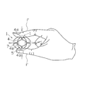
ボルト、ナットキャップ1には、図1、図2に示すように、下面部に開口部4cを有するように形成された楕円柱状のカバー部4が形成されている。該カバー部4の高さAは、図6に示すように、ボルト2の頭部2aの高さB、及びナット3の高さC以上に形成されていることが好ましく、これにより、これらに取付けられた、ボルト、ナットキャップ1が容易に外れることがなく、また、横から見ても当該ボルト、ナットキャップ1が取付けられていることを目視で確認しやすい。そして、カバー部4の短軸方向の長さは、図4、図5に示すように、ボルト2の頭部2a、及びナット3を挟持することができるように、これらの幅よりも小さく形成されている。そして、カバー部4の長軸方向の長さは、図3に示すように、当該カバー部4を長軸方向から作業者が指Fでつまむように挟持して、短軸方向の長さをボルト2の頭部2a、及びナット3の幅よりも大きくした場合にも、該カバー部4の長軸方向の長さがこれらの幅よりも大きくなるように形成されている。
As shown in FIGS. 1 and 2, the bolt and
そして、カバー部4の上面部4aには、図1、図2、図6に示すように、ボルト2のネジ部2bを挿入可能な略円形の挿通孔4bが形成されると共に、該上面部4aの長軸方向に相対向して該挿通孔4bから外側方向に内側切込み5が形成されている。そして、カバー部4の長軸方向の側面には、図1、図3に示すように、作業者が指Fで挟持しやすいように、相対向して内側切込み7と略垂直方向に平面部4dが形成されている。尚、内側切込み5は、挿通孔4bの内縁部41bから外周方向にカバー部4の長軸方向の平面部4dに至るまで形成されていることが、図3に示すように、ボルト、ナットキャップ1を作業者が指Fでつまんだ際に当該カバー部4が変形しやすく好ましい。
The
そして、ボルト、ナットキャップ1を、図6に示すように、ボルト2のネジ部2bを挿通孔4bに挿通させると共に、ナット3に取付けた場合に、図4、図6に示すように、カバー部4の短軸方向の長さがナット3によって押し広げられ、挿通孔4bが略楕円形になった際に、該挿通孔4bの内縁部41bと内側切込み5とが形成する角部8がネジ部2bのネジ溝に係止され、これにより、当該ボルト、ナットキャップ1が容易に外れることがない。また、カバー部4の下端縁部から外側方向に略円形に鍔部6が形成され、該鍔部6にはカバー部4の上面部4aに形成された内側切込み5と略垂直方向に該鍔部6の外縁部6aから内側方向に相対向して外側切込み7が形成されている。尚、外側切込み7は、鍔部6の外縁部6aからカバー部4に至るまで形成されていることが、図3に示すように、ボルト、ナットキャップ1を作業者が指Fでつまんだ際に当該鍔部6が変形しやすく好ましい。
When the bolt and
以上のように形成されるボルト、ナットキャップ1の使用方法について以下に示す。
The method for using the bolt and
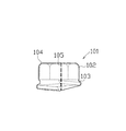
図6は部材9、10をボルト2、ナット3、及びワッシャー11等を用いて連結した例である。そして、ボルト、ナットキャップ1をボルト2の頭部2a、又はナット3に取付ける際には、図3に示すように、作業者が指Fでそのカバー部4の長軸方向の側面に形成された平面部4dをつまんで挟持することにより、図4、図5に示すように、内側切込み5が歪を吸収するように開きカバー部4の長軸方向の長さが小さくなると共に、短軸方向の長さが大きくなるように変形する。その際には、略円形に形成された挿通孔4bも前述のカバー部4の変形に伴い、該カバー部4の短軸方向が長軸となるような楕円形に変形する。さらに、同時に外側切込み7が略円形の鍔部6に生じる歪を吸収するように開き当該鍔部6も、楕円形に変形した挿通孔4bと同方向に長軸を有する楕円形に変形する。
FIG. 6 shows an example in which
そして、前述のようにして、カバー部4の短軸方向の長さが、ボルト2の頭部2a、又はナット3の幅よりも大きくなった段階で、該カバー部4の下面の開口部4cを当該ボルト2の頭部2a、又はナット3に被せる。そして、作業者が指Fの挟持を開放することにより、前述のように変形したカバー部4等が弾性回復して、該カバー部4の内側面とボルト2の頭部2a、又はナット3の角部2c、3aとが接触し、これらを挟持する。また、図4に示すように、挿通孔4bにボルト2のネジ部2bを挿入すると共に、ナット3にボルト、ナットキャップ1を取付けた場合には、内側切込み5と挿通孔4bの内縁部41bが形成する角部8が当該ネジ部2bのネジ溝に係止される。
Then, as described above, when the length in the minor axis direction of the
ここで、一旦締め付けられた軸組どおしの出入りを合わせる等の微調整を行う場合のように、一旦締め付けられたボルト2、又はナット3を何らかの理由で緩める際には、ボルト、ナットキャップ1を取外す必要があるが、この状態ではレンチ等でボルト2、又はナット3を緩めることができないので、作業者が指Fでカバー部4の平面部4dを再びつまんで挟持する等すれば、容易に取外すことができる。
Here, when loosening the
尚、ボルト、ナットキャップ1は、従来のようにマーキングを行った場合には視認しずらく、検査用突き棒では脚立を使用しないと届かないような、床梁の横綴り部分や、該床梁の水平ブレース、そして母屋、垂木、棟木等から構成される小屋組等に好適に使用することができる。また、小屋組では、落下防止の水平ネットの設置中や、該小屋組のうち地上で施工可能なものに関しては地上でボルト、ナットキャップ1を取付けることが安全上好ましい。
The bolts and
このように、ボルト、ナットキャップ1は、ボルト2、又はナット3を締めた後にこれらに取付けることで、該ボルト2、又はナット3の締め忘れの確認を目視で容易に行うことができる。すなわち、ボルト、ナットキャップ1が取付けられたボルト2、又はナット3は締め付けが完了していることになる。そして、ボルト2、又はナット3を締めた後に何らかの理由でこれらを緩める場合があるとしても、ボルト、ナットキャップ1が取付けられた状態ではレンチ等でこれらを緩めることができない。そのため、一旦ボルト、ナットキャップ1を取外す必要があり、緩めたボルト2、又はナット3を再度締め忘れたとしても、このボルト2、又はナット3には当該ボルト、ナットキャップ1が取付けられていないので、これが締められていないと目視で判断することができる。尚、ボルト、ナットキャップ1の取付け作業は、これが取付けられるボルト2、ナット3を締め付けた作業者と同一の作業者が行うことが好ましいが、別の作業者が取付けてもよいのは勿論である。
In this way, the bolt and
本発明に係るボルト、ナットキャップ1は、戸建住宅の施工を始め、マンション、その他の構造物にも使用することができる。
The bolt and
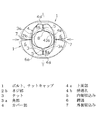
1 ボルト、ナットキャップ
2 ボルト
2a 頭部
2b ネジ部
2c 角部
3 ナット
4 カバー部
4a 上面部
4b 挿通孔
41b 内縁部
5 内側切込み
6 鍔部
6a 外縁部
7 外側切込み
1 bolt,
Claims (5)
前記ボルトの頭部、又は前記ナットを覆う可撓性部材からなる略楕円柱状のカバー部と、
該カバー部の略楕円形の上面部に前記ボルトのネジ部を挿通可能に形成された略円形の挿通孔と、
前記上面部の長軸方向に相対向して前記挿通孔の内縁部から外周方向に向かって形成された内側切込みと、
前記カバー部の下方縁部から外側方向に略円形となるように設けられた鍔部と、
前記内側切込みと略垂直方向に相対向して該鍔部の外縁部から内側方向に形成された外側切込みと、を有しハット型に形成されたことを特徴とするボルト、ナットキャップ。 In bolts and nut caps that are attached to the bolt heads or nuts to prevent forgetting to tighten them,
A substantially elliptical column-shaped cover portion made of a flexible member covering the head of the bolt or the nut;
A substantially circular insertion hole formed on the upper surface of the substantially oval shape of the cover portion so that the threaded portion of the bolt can be inserted;
An inner notch formed facing the outer peripheral direction from the inner edge of the insertion hole opposite to the major axis of the upper surface,
A collar portion provided so as to be substantially circular in the outer direction from the lower edge of the cover portion;
A bolt and a nut cap, wherein the bolt and nut cap are formed in a hat shape having an outer notch formed in an inner direction from an outer edge portion of the flange portion so as to face the inner notch in a substantially vertical direction.
Priority Applications (1)
| Application Number | Priority Date | Filing Date | Title |
|---|---|---|---|
| JP2008106362A JP4911368B2 (en) | 2008-04-16 | 2008-04-16 | Bolts, nut caps, and confirmation methods for forgetting bolts and nuts |
Applications Claiming Priority (1)
| Application Number | Priority Date | Filing Date | Title |
|---|---|---|---|
| JP2008106362A JP4911368B2 (en) | 2008-04-16 | 2008-04-16 | Bolts, nut caps, and confirmation methods for forgetting bolts and nuts |
Publications (2)
| Publication Number | Publication Date |
|---|---|
| JP2009257448A JP2009257448A (en) | 2009-11-05 |
| JP4911368B2 true JP4911368B2 (en) | 2012-04-04 |
Family
ID=41385125
Family Applications (1)
| Application Number | Title | Priority Date | Filing Date |
|---|---|---|---|
| JP2008106362A Expired - Fee Related JP4911368B2 (en) | 2008-04-16 | 2008-04-16 | Bolts, nut caps, and confirmation methods for forgetting bolts and nuts |
Country Status (1)
| Country | Link |
|---|---|
| JP (1) | JP4911368B2 (en) |
Families Citing this family (2)
| Publication number | Priority date | Publication date | Assignee | Title |
|---|---|---|---|---|
| JP6049408B2 (en) * | 2012-11-08 | 2016-12-21 | ニッタ株式会社 | Loosening prevention mechanism for joint nut |
| JP5918428B1 (en) * | 2015-09-18 | 2016-05-18 | 株式会社フクデン | Fall prevention tool |
Family Cites Families (3)
| Publication number | Priority date | Publication date | Assignee | Title |
|---|---|---|---|---|
| JPS5573607A (en) * | 1978-11-28 | 1980-06-03 | Taizo Yamashita | Novel method to remove fundamentally cause of extremely uncurable smell of armpit by only administering certain antibiotic or applying it affected part |
| JPH1061643A (en) * | 1996-08-23 | 1998-03-06 | Toyo Tire & Rubber Co Ltd | Protective cover for connecting member |
| JPH10110717A (en) * | 1996-10-04 | 1998-04-28 | Katsumi Ikeda | Husk female screw body and method to prevent female screw body from being left unfastened |
-
2008
- 2008-04-16 JP JP2008106362A patent/JP4911368B2/en not_active Expired - Fee Related
Also Published As
| Publication number | Publication date |
|---|---|
| JP2009257448A (en) | 2009-11-05 |
Similar Documents
| Publication | Publication Date | Title |
|---|---|---|
| US6345420B1 (en) | Mounting structure for energy absorber | |
| DE3825082C2 (en) | ||
| JP4911368B2 (en) | Bolts, nut caps, and confirmation methods for forgetting bolts and nuts | |
| DE202010010858U1 (en) | Fastening device for systems on trapezoidal or corrugated metal roofs or trapezoidal or corrugated metal facades | |
| JP2011038384A (en) | Panel for roof and mounting structure of panel for roof | |
| DE202006008867U1 (en) | Device for fixing solar energy unit on roof has hanger bolt with upper metric thread for nut which presses an upper sealing element aainst contact pressure element which presses lower sealing element against flat metal roofing | |
| US6612642B2 (en) | Structure and method for installing exterior part | |
| JP5255384B2 (en) | Panel support structure for folded metal roof | |
| JP2003056147A (en) | Mounting structure for solar battery panel | |
| KR101379245B1 (en) | A blinker device | |
| JP2014152531A (en) | Other object fixture | |
| JP4056548B1 (en) | Safety belt attachment | |
| JP4767612B2 (en) | Protection sheet structure | |
| JP2010024636A (en) | Panel frame and panel of prefabricated building, and panel assembling device and panel assembling method for prefabricated building | |
| JP6979868B2 (en) | fence | |
| WO2021001295A1 (en) | Electronic arrangement for an aircraft and method for providing such an electronic arrangement | |
| US20190225010A1 (en) | Cap member for wheel mounting nut, and method of mounting wheel | |
| US20080304933A1 (en) | Bolt holding member | |
| JP3448257B2 (en) | Roof repair method and roof repair structure and roof repair clamps used for them | |
| DE202019104488U1 (en) | Cover cap | |
| KR102699585B1 (en) | Shade Structures | |
| DE102012208340A1 (en) | Splash guard cover holding order | |
| CN223853896U (en) | Tool type edge protection fixing and connecting device | |
| CN222334168U (en) | Easy-to-detach automobile interior trim fastener | |
| KR200429200Y1 (en) | Base station antenna facility device for mobile communication |
Legal Events
| Date | Code | Title | Description |
|---|---|---|---|
| A621 | Written request for application examination |
Free format text: JAPANESE INTERMEDIATE CODE: A621 Effective date: 20101006 |
|
| A977 | Report on retrieval |
Free format text: JAPANESE INTERMEDIATE CODE: A971007 Effective date: 20110930 |
|
| TRDD | Decision of grant or rejection written | ||
| A01 | Written decision to grant a patent or to grant a registration (utility model) |
Free format text: JAPANESE INTERMEDIATE CODE: A01 Effective date: 20111222 |
|
| A01 | Written decision to grant a patent or to grant a registration (utility model) |
Free format text: JAPANESE INTERMEDIATE CODE: A01 |
|
| A61 | First payment of annual fees (during grant procedure) |
Free format text: JAPANESE INTERMEDIATE CODE: A61 Effective date: 20120104 |
|
| R150 | Certificate of patent or registration of utility model |
Ref document number: 4911368 Country of ref document: JP Free format text: JAPANESE INTERMEDIATE CODE: R150 Free format text: JAPANESE INTERMEDIATE CODE: R150 |
|
| FPAY | Renewal fee payment (event date is renewal date of database) |
Free format text: PAYMENT UNTIL: 20150127 Year of fee payment: 3 |
|
| R250 | Receipt of annual fees |
Free format text: JAPANESE INTERMEDIATE CODE: R250 |
|
| R250 | Receipt of annual fees |
Free format text: JAPANESE INTERMEDIATE CODE: R250 |
|
| LAPS | Cancellation because of no payment of annual fees |