JP4910488B2 - Management device and network system for investigating network path status - Google Patents
Management device and network system for investigating network path status Download PDFInfo
- Publication number
- JP4910488B2 JP4910488B2 JP2006155724A JP2006155724A JP4910488B2 JP 4910488 B2 JP4910488 B2 JP 4910488B2 JP 2006155724 A JP2006155724 A JP 2006155724A JP 2006155724 A JP2006155724 A JP 2006155724A JP 4910488 B2 JP4910488 B2 JP 4910488B2
- Authority
- JP
- Japan
- Prior art keywords
- packet
- probe
- probe packet
- network
- address information
- Prior art date
- Legal status (The legal status is an assumption and is not a legal conclusion. Google has not performed a legal analysis and makes no representation as to the accuracy of the status listed.)
- Expired - Fee Related
Links
Images


Classifications
-
- H—ELECTRICITY
- H04—ELECTRIC COMMUNICATION TECHNIQUE
- H04L—TRANSMISSION OF DIGITAL INFORMATION, e.g. TELEGRAPHIC COMMUNICATION
- H04L43/00—Arrangements for monitoring or testing data switching networks
- H04L43/08—Monitoring or testing based on specific metrics, e.g. QoS, energy consumption or environmental parameters
- H04L43/0805—Monitoring or testing based on specific metrics, e.g. QoS, energy consumption or environmental parameters by checking availability
- H04L43/0811—Monitoring or testing based on specific metrics, e.g. QoS, energy consumption or environmental parameters by checking availability by checking connectivity
-
- H—ELECTRICITY
- H04—ELECTRIC COMMUNICATION TECHNIQUE
- H04L—TRANSMISSION OF DIGITAL INFORMATION, e.g. TELEGRAPHIC COMMUNICATION
- H04L43/00—Arrangements for monitoring or testing data switching networks
- H04L43/12—Network monitoring probes
-
- H—ELECTRICITY
- H04—ELECTRIC COMMUNICATION TECHNIQUE
- H04L—TRANSMISSION OF DIGITAL INFORMATION, e.g. TELEGRAPHIC COMMUNICATION
- H04L45/00—Routing or path finding of packets in data switching networks
Description
本発明は、網の経路状態を調査する管理装置、及びその網システムに関する。詳しくは、網の経路状態が即時取得可能で経路変動も検出可能な管理装置等に関する。 The present invention relates to a management apparatus for investigating a network path state and a network system thereof. More specifically, the present invention relates to a management device that can immediately acquire a route state of a network and detect a route change.
従来から、網(又はネットワーク、以下「網」と称す)の経路状態を把握するコマンドとして、tracerouteコマンドがある。 Conventionally, there is a traceroute command as a command for grasping a route state of a network (or network, hereinafter referred to as “network”).
traceroutコマンドの起動により、TTL(Time to Live:パケットの有効期限)を「1」から順に大きくしたパケットが宛て先アドレスに送出される。TTLの値に従い、当該コマンドを発行した端末から数えて1ホップ目、2ホップ目、・・・のネットワークノードは、有効期限エラーを示すパケットを返信する。宛て先アドレスの端末がこのパケットを返信するまで、TTLを順に大きくすることで、その間の経路が明らかになる。 When the tracerout command is activated, packets whose TTL (Time to Live: packet expiration date) is increased from “1” in order are sent to the destination address. According to the value of TTL, the network node of the first hop, the second hop,... Counted from the terminal that issued the command returns a packet indicating an expiration date error. By increasing the TTL in order until the terminal at the destination address returns this packet, the route between them becomes clear.
また、他の従来技術として、コマンド発行端末から経路トレースを示すフラグを付したフォーマット信号が送信され、各ノードは受信ポートのアドレス及び送出ポートのアドレスを付加して次のノードに送信し、付加累積された受信ポート及び送出ポートのアドレスの繋がりから送信経路をトレースするようにしたものがある(例えば、以下の特許文献1)。 As another conventional technique, a format issue signal with a flag indicating a path trace is transmitted from the command issuing terminal, and each node adds the address of the reception port and the address of the transmission port and transmits to the next node. There is one in which a transmission path is traced from a connection of accumulated addresses of a reception port and a transmission port (for example, Patent Document 1 below).
更に、送信されたフィルタ設定パケットから、経路に沿った動的パケットフィルタを設定し、このフィルタによって検出されたデータの収集により、ネットワーク内の実パケットを追跡することで、経路情報を取得するようにしたものも開示される(例えば、以下の特許文献2)。
しかしながら、tracerouteコマンドは、網オペレータ又はユーザ(以下、「網オペレータ等」と称す)が自ら端末を操作して発行させる必要がある。元来、当該コマンドは、網オペレータ等が何らかの方法で網の障害を認識した後で発行されるコマンドである。従って、障害発生時点で当該コマンドを発行した場合でなければ、障害発生時点での経路状態を取得することは困難である。 However, the traceroute command needs to be issued by a network operator or a user (hereinafter referred to as “network operator or the like”) by operating the terminal himself / herself. Originally, this command is a command issued after a network operator or the like recognizes a network failure in some way. Therefore, unless the command is issued at the time of failure, it is difficult to acquire the path state at the time of failure.
また、tracerouteコマンドの発行をスクリプト等により、ある程度自動化(例えば、一定時間)することも考えられる。しかし、同様に、障害が発生した時点でコマンドが発行されなければ障害発生時点での経路状態を取得することは困難である。 It is also conceivable that the issue of the traceroute command is automated to some extent (for example, for a certain period of time) using a script or the like. However, similarly, if a command is not issued when a failure occurs, it is difficult to acquire the path state at the time of the failure.
更に、tracerouteコマンドはその場限りのコマンドであり、当該コマンドの起動により発行される各パケットにおいて、その前後の結果を比較して経路変動を把握することはできない。従って、当該コマンドでは、経路が変動した場合でも、網オペレータ等に通知することができない。 Furthermore, the traceroute command is an ad hoc command, and it is not possible to grasp the path fluctuation by comparing the results before and after each packet issued by the activation of the command. Therefore, this command cannot notify the network operator or the like even when the route changes.
一方、特許文献1及び2に関しても、フォーマット信号やフィルタ設定パケットを網オペレータ等が端末の操作により自ら発行させる必要があり、障害発生時点での経路状態を取得することが困難である。 On the other hand, with respect to Patent Documents 1 and 2, it is necessary for a network operator or the like to issue a format signal or a filter setting packet by operating the terminal, and it is difficult to acquire a path state at the time of failure occurrence.
そこで、本発明は、上記問題点に鑑みてなされたもので、その目的は、ユーザトラフィックに応じて網の経路状態を即時取得できる管理装置、管理方法、プログラム、及びその網システムを提供することにある。 Accordingly, the present invention has been made in view of the above problems, and an object thereof is to provide a management device, a management method, a program, and a network system thereof that can immediately acquire a network path state according to user traffic. It is in.
また、本発明の他の目的は、網の経路変動を検出できる管理装置等を提供することにある。 Another object of the present invention is to provide a management device or the like that can detect network path fluctuations.
上記目的を達成するために、本発明の一実施態様によれば、網の経路状態を調査する管理装置において、前記網からのトラフィックを受信するパケット送受信部と、受信した前記トラフィックから、アドレス情報を抽出するアドレス抽出部と、抽出された前記アドレス情報を送信先とするプローブパケットを生成するプローブパケット生成部とを備え、前記パケット送受信部は、生成された前記プローブパケットを前記網に送信するとともに、前記トラフィックが転送される前記網の経路に沿って送信された前記プローブパケットに対するプローブ応答パケットを受信することを特徴とする。 In order to achieve the above object, according to one embodiment of the present invention, in a management device for examining a route condition of a network, a packet transmitting / receiving unit that receives traffic from the network, and address information from the received traffic And a probe packet generation unit that generates a probe packet having the extracted address information as a transmission destination, and the packet transmission / reception unit transmits the generated probe packet to the network. And a probe response packet for the probe packet transmitted along the network path to which the traffic is transferred is received.
また、本発明の他の実施態様によれば、前記管理装置において、更に、前記プローブ応答パケットから経路情報を作成し、前記経路情報を保存する結果保存部を備えることを特徴する。 According to another embodiment of the present invention, the management device further includes a result storage unit that generates route information from the probe response packet and stores the route information.
更に、本発明の他の実施態様によれば、前記管理装置において、前記結果保存部は、保存した第1の経路情報と、新たに受信した前記プローブ応答パケットから作成した第2の経路情報とを比較することで、前記網に転送される前記トラフィックの経路の変動を検出することを特徴とする。 Furthermore, according to another embodiment of the present invention, in the management device, the result storage unit includes the stored first path information and the second path information created from the newly received probe response packet. To detect a change in the route of the traffic transferred to the network.
更に、本発明の他の実施態様によれば、前記管理装置において、前記ユーザトラフィック抽出部は、抽出した前記アドレス情報を保存し、新たに受信した前記トラフィックから抽出した前記アドレス情報と同一のときは、前記プローブパケット生成部に対し前記プローブパケットを生成させないようにすることを特徴とする。 Furthermore, according to another embodiment of the present invention, in the management device, when the user traffic extraction unit stores the extracted address information and is the same as the address information extracted from the newly received traffic. The probe packet generator is configured not to generate the probe packet.
更に、本発明の他の実施態様によれば、前記管理装置において、前記ユーザトラフィック抽出部は、保存した前記アドレス情報を一定時間経過後消去することを特徴とする。 Furthermore, according to another embodiment of the present invention, in the management device, the user traffic extraction unit deletes the stored address information after a predetermined time has elapsed.
更に、本発明の他の実施態様によれば、前記管理装置において、前記パケット送受信部は、前記プローブ応答パケットを受信するともに、前記網に転送されずループバック機能により前記プローブパケットを受信し、前記結果保存部は、前記プローブ応答パケットと、前記ループバック機能により受信した前記プローブパケットとから前記経路情報を作成することを特徴とする。 Furthermore, according to another embodiment of the present invention, in the management device, the packet transmission / reception unit receives the probe response packet and receives the probe packet by a loopback function without being transferred to the network. The result storage unit creates the route information from the probe response packet and the probe packet received by the loopback function.
更に、本発明の他の実施態様によれば、前記管理装置において、前記プローブパケット生成部は抽出された前記アドレス情報に対して予め設定されたホップ数分の前記プローブパケットを生成することを特徴とする。 Furthermore, according to another embodiment of the present invention, in the management device, the probe packet generation unit generates the probe packets for a preset number of hops with respect to the extracted address information. And
更に、本発明の他の実施態様によれば、前記管理装置において、前記プローブパケット生成部は前記プローブパケットごとに異なる識別子を生成された前記プローブパケットに付加することを特徴とする。 Furthermore, according to another embodiment of the present invention, in the management device, the probe packet generation unit adds a different identifier for each probe packet to the generated probe packet.
更に、本発明の他の実施態様によれば、前記管理装置において、前記識別子は前記プローブパケットの送信先であるターゲットごとにユニークなシーケンス番号と、送信される前記プローブパケットのホップ数を示す値とを含むことを特徴とする。 Furthermore, according to another embodiment of the present invention, in the management device, the identifier includes a unique sequence number for each target to which the probe packet is transmitted and a value indicating the number of hops of the probe packet to be transmitted. It is characterized by including.
更に、本発明の他の実施態様によれば、前記管理装置において、前記結果保存部は前記シーケンス番号が同一の前記プローブ応答パケットを同一エントリ内にまとめて保存することを特徴とする。 Furthermore, according to another embodiment of the present invention, in the management device, the result storage unit stores the probe response packets having the same sequence number together in the same entry.
更に、本発明の他の実施態様によれば、前記管理装置において、前記プローブ応答パケットには前記プローブパケットの送信された前記ターゲットのアドレス情報が含まれ、前記結果保存部には前記アドレス情報が前記エントリ内に含まれることを特徴とする。 Furthermore, according to another embodiment of the present invention, in the management device, the probe response packet includes address information of the target to which the probe packet has been transmitted, and the result storage unit includes the address information. It is included in the entry.
また、上記目的を達成するために本発明の他の実施態様によれば、網の経路状態を調査する管理方法において、前記網からのトラフィックを受信し、受信した前記トラフィックから、アドレス情報を抽出し、抽出された前記アドレス情報を送信先とするプローブパケットを生成し、生成された前記プローブパケットを前記網に送信するとともに、前記トラフィックが転送される前記網の経路に沿って送信された前記プローブパケットに対するプローブ応答パケットを受信することを特徴とする。 In order to achieve the above object, according to another embodiment of the present invention, in a management method for investigating a route state of a network, traffic from the network is received and address information is extracted from the received traffic. And generating a probe packet having the extracted address information as a transmission destination, transmitting the generated probe packet to the network, and transmitting the traffic along the route of the network. A probe response packet for the probe packet is received.
更に、上記目的を達成するために本発明の他の実施態様によれば、網の経路状態を調査する管理プログラムにおいて、前記網からのトラフィックを受信する処理と、受信した前記トラフィックから、アドレス情報を抽出する処理と、抽出された前記アドレス情報を送信先とするプローブパケットを生成する処理と、生成された前記プローブパケットを前記網に送信するとともに、前記トラフィックが転送される前記網の経路に沿って送信された前記プローブパケットに対するプローブ応答パケットを受信する処理と、をコンピュータに実行させることを特徴とする。 Furthermore, in order to achieve the above object, according to another embodiment of the present invention, in a management program for investigating a route state of a network, a process for receiving traffic from the network, and address information from the received traffic , A process of generating a probe packet having the extracted address information as a transmission destination, a transmission of the generated probe packet to the network, and a route of the network to which the traffic is transferred And a process of receiving a probe response packet with respect to the probe packet transmitted along the network.
更に、上記目的を達成するために本発明の他の実施態様によれば、端末とサーバとが網を介して接続されるとともに、網の経路状態を調査する管理装置が前記網に接続された網システムにおいて、前記管理装置には、前記端末から前記サーバに転送されるトラフィックを受信するパケット送受信部と、受信した前記トラフィックから、アドレス情報を抽出するアドレス抽出部と、抽出された前記アドレス情報を送信先とするプローブパケットを生成するプローブパケット生成部とを備え、前記パケット送受信部は、生成された前記プローブパケットを前記網に送信するとともに、前記トラフィックが転送される前記網の経路に沿って送信された前記プローブパケットに対するプローブ応答パケットを受信することを特徴とする。 Furthermore, in order to achieve the above object, according to another embodiment of the present invention, a terminal and a server are connected via a network, and a management device for investigating the route state of the network is connected to the network. In the network system, the management device includes a packet transmission / reception unit that receives traffic transferred from the terminal to the server, an address extraction unit that extracts address information from the received traffic, and the extracted address information A probe packet generation unit that generates a probe packet having a transmission destination as the transmission destination, wherein the packet transmission / reception unit transmits the generated probe packet to the network and follows a route of the network to which the traffic is transferred Receiving a probe response packet with respect to the probe packet transmitted in the above manner.
本発明によれは、ユーザトラフィックに応じて網の経路状態を即時取得できる管理装置、管理方法、プログラム、及びその網システムを提供することができる。また、本発明によれば、網の経路変動を検出できる管理装置等を提供することができる。 According to the present invention, it is possible to provide a management apparatus, a management method, a program, and a network system thereof that can immediately acquire a network path state according to user traffic. In addition, according to the present invention, it is possible to provide a management device or the like that can detect network path fluctuations.
以下、図面を参照して本発明を実施するための最良の形態を説明する。 The best mode for carrying out the present invention will be described below with reference to the drawings.
まず、実施例1について説明する。本実施例1は、網に転送されるトラフィック(又はパケットデータ)をキャプチャし、そのパケットと同じアドレスを持つプローブパケットを、トラフィックの転送と略同時に網に転送させて、その応答パケット等を保存する等により、経路状態を即時に取得することができるようにした例である。 First, Example 1 will be described. In the first embodiment, traffic (or packet data) transferred to the network is captured, and a probe packet having the same address as that packet is transferred to the network almost simultaneously with the traffic transfer, and the response packet is stored. This is an example in which the route state can be acquired immediately by, for example.
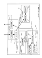
図1は、実施例1において適用されるネットワークシステム(網システム)100の構成例を示す図である。ネットワークシステム100は、キャプチャ/プローブ端末(以下、「キャプチャ端末」と称す)1と、端末200と、サーバ400とから構成される。キャプチャ端末1等はIP(Internet Protocol)ネットワーク300を介して互いに接続される。
FIG. 1 is a diagram illustrating a configuration example of a network system (network system) 100 applied in the first embodiment. The network system 100 includes a capture / probe terminal (hereinafter referred to as “capture terminal”) 1, a
また、IPネットワーク300は、複数のノード310〜370を有し、図1に示す経路により互いに接続される。
The
図2は、キャプチャ端末1の構成例を示す図である。キャプチャ端末1は、パケット送受信部10と、ユーザトラフィック抽出部20と、プローブパケット生成部30、及びプローブ受信部40を備える。このキャプチャ端末1が、網の経路状態を調査する管理装置としての役割を果たす。
FIG. 2 is a diagram illustrating a configuration example of the capture terminal 1. The capture terminal 1 includes a packet transmission /
パケット送受信部10は、パケット受信部11と、振り分け部12、及びパケット送信部13を備える。
The packet transmission /
パケット受信部11は、端末200や各ノード310〜370、サーバ400から送信されたパケットデータを受信する。
The
振り分け部12は、パケット受信部11で受信したパケットが、ユーザトラフィックのパケットか、後述するプローブ応答パケット(或いはプローブパケット)か、を判別する。そして、振り分け部12は、ユーザトラフィックのパケットをユーザトラフィック抽出部20に、プローブ応答パケット等はプローブ受信部40に振り分ける(又は、廃棄する)。振り分けは、受信したパケットデータのプロトコルフィールドやポート番号を利用する。詳細は後述する。
The
パケット送信部13は、プローブパケット生成部30で生成されたプローブパケットを、IPネットワーク300を介して、端末200や各ノード310〜370、サーバ400に送信する。前述のプローブ応答パケットは、プローブパケットを受信した各ノード310〜370等がキャプチャ端末1に対して送信するパケットである。
The
ユーザトラフィック抽出部20は、アドレス抽出部21を備える。アドレス抽出部21は、ユーザトラフィックのパケットから、送信元アドレス(Srcアドレス)と、宛て先アドレス(Dstアドレス)とを抽出する。アドレス抽出部21は、抽出した送信元アドレス等をプローブパケット生成部30に出力する。
The user
プローブパケット生成部30は、パケット生成部31と、ターゲット定義テーブル32と、シーケンス値カウンタ33とを備える。
The
パケット生成部31は、送信元アドレスと宛て先アドレスとから、プローブパケットを生成する。パケット生成部31は、ターゲット定義テーブル32を参照して、合致した送信元アドレス及び宛て先アドレスの組がある場合にプローブパケットを生成する。また、パケット生成部31は、シーケンス値カウンタ33を参照し、プローブパケットのシーケンス番号を演算し、プローブパケットの所定フィールドに格納する。詳細は後述する。パケット生成部31は、生成したプローブパケットをパケット送信部13に出力する。
The
ターゲット定義テーブル32は、プローブパケットの送信を行うターゲットを定義するテーブルである。具体的には、ターゲット定義テーブル32には、ターゲット(プローブパケットの送信先)のアドレスが記憶される。 The target definition table 32 is a table that defines targets for transmitting probe packets. More specifically, the target definition table 32 stores the address of the target (probe packet transmission destination).
シーケンス値カウンタ33は、シーケンス番号のベースとなる値を保持するカウンタである。シーケンス番号は、どのターゲット宛てのプローブパケットか、ターゲットの重複を識別するために、或いは、ターゲットが同じになるようなプローブパケットを送信するときにターゲットの重複を区別するために、プローブパケットに付与される番号である。詳細は後述する。
The
プローブ受信部40は、結果保存部41と、結果保存データベース(DB)42とを備える。
The
結果保存部41は、振り分け部12からのプローブパケットとプローブ応答パケットとを分類して結果保存DB42に格納する。結果保存DB42には、後述するように各パケットに基づくエントリが記憶され、調査した経路状態を把握することができる。
The
次に、キャプチャ端末1の動作について説明するが、その前に、まずユーザトラフィックのパケットである、IPパケットの例について説明する。 Next, the operation of the capture terminal 1 will be described. Before that, an example of an IP packet, which is a user traffic packet, will be described first.
図3(A)は、パケット受信部11で受信するIPパケット500の構成例を示す図である。IPパケット500は、プロトコルを識別するためのデータが格納されるプロトコルフィールド510と、送信元と宛て先の夫々のIPアドレスが格納される送信元IPアドレスフィールド511及び宛て先IPアドレスフィールド512と、送信元と宛て先の夫々のポート番号が格納される送信元ポート番号フィールド513及び宛て先ポート番号フィールド514と、種々のデータが格納されるペイロード515とから構成される。
FIG. 3A is a diagram illustrating a configuration example of the
パケット送受信部10の振り分け部12では、パケットを振り分けることになるが、例としてHTTPパケットをユーザトラフィックのパケットとした場合は以下のようになる。即ち、振り分け部12は、送信元ポート番号と宛て先ポート番号とを、受信したIPパケット500の該当フィールド513、514から取り出す。そして、そのいずれかの番号が「80」又は「8080」のとき、振り分け部12は受信したパケットがHTTPパケットであるとしてユーザトラフィック抽出部20に出力する。
The
なお、振り分け部12は、ユーザトラフィックのパケットを振り分けた後、引き続いてプローブパケット、プローブ応答パケットの振り分け処理を行う。即ち、受信したIPパケット500のプロトコルフィールド510を取り出し、それがプローブパケット又はプローブ応答パケット(ICMPパケット)であることを示すものであったとき、振り分け部12は受信したパケットがプローブパケット又はプローブ応答パケットであるとしてプローブ受信部40に出力する。
The
図4は、ユーザトラフィック抽出部20で実行されるアドレス抽出処理のフローチャートの例である。
FIG. 4 is an example of a flowchart of address extraction processing executed by the user
まず、ユーザトラフィック抽出部20は、アドレス抽出機能を実行するための処理を開始すると(S10)、振り分け部12から出力されたHTTPパケットから、送信元アドレス(Srcアドレス)と宛て先アドレス(Dstアドレス)とを抽出する(S11)。そして、抽出した各アドレスをプローブパケット生成部30のパケット生成部31に出力する(S12)。そして、アドレス抽出機能の処理が終了する。
First, when the user
その後、プローブパケット生成部30において、抽出したアドレスに基づいて、プローブパケットの生成機能が実行される。図5は、そのフローチャートの例である。
Thereafter, the probe
尚、本実施例では、この機能が実行される前に、以下の処理が行われる。まず、オペレータ等は、ターゲット定義テーブル32にターゲットを記憶しておく。図3(B)は、ターゲット定義テーブル32の例である。同図に示すように、プローブパケットのターゲットとなるべき、サーバ400等のアドレスが記憶される。
In this embodiment, the following processing is performed before this function is executed. First, the operator or the like stores the target in the target definition table 32. FIG. 3B is an example of the target definition table 32. As shown in the figure, the address of the
また、オペレータ等はプローブパケットを送信するホップ数も予め設定しておく。例えば、キャプチャ端末1のメモリ等に記憶する。調査したいホップ数を設定するもので、網の規模等によって数も変動する。 The operator or the like also sets the number of hops for transmitting the probe packet in advance. For example, it is stored in the memory of the capture terminal 1 or the like. The number of hops to be investigated is set, and the number varies depending on the size of the network.
更に、オペレータ等は、シーケンス値カウンタ33を任意の値で初期化する。 Further, the operator or the like initializes the sequence value counter 33 with an arbitrary value.
本実施例では、ターゲット定義テーブル32を「*」(すべてのターゲット、即ち、ノード310を通る全てのHTTPパケットを対象にする)、ホップ数を「5」、シーケンス値カウンタ33の初期値を「1」とする。
In the present embodiment, the target definition table 32 is set to “*” (for all targets, ie, all HTTP packets passing through the node 310), the hop count is set to “5”, and the initial value of the
図5に戻り、プローブパケット生成機能を実行するための処理が開始されると(S20)、パケット生成部31は、TTLカウンタ値を「0」にして初期化する(S21)。
Returning to FIG. 5, when the process for executing the probe packet generation function is started (S20), the
TTLカウンタ値とは、送信するプローブパケットのホップ数をカウントするための値である。予め設定されたホップ数分のプローブパケットの生成が終了すると、プローブ生成処理が終了する。 The TTL counter value is a value for counting the number of hops of the probe packet to be transmitted. When the generation of probe packets for the preset number of hops is completed, the probe generation process ends.
次いで、パケット生成部31は、ターゲット定義テーブル32に記憶されたエントリを参照して、ユーザトラフィック抽出部20で抽出されたアドレスがターゲット定義テーブル32に存在するか否かを判断する(S22)。ターゲット定義テーブル32に存在しないと(S22で「ない」)、プローブパケット生成機能は終了する。
Next, the
一方、ターゲット定義テーブル32に抽出したアドレスが存在すれば(S22で「あり」)、パケット生成部31は、TTLカウンタ値を「+1」加算する(S23)。上記設定では、ターゲット定義テーブル32は「*」のため、抽出したアドレスが存在し、TTLカウンタ値が「1」となる。
On the other hand, if the extracted address exists in the target definition table 32 (“Yes” in S22), the
次いで、パケット生成部31は、実際にプローブパケットの生成処理(S24、S25)を行う。2つの処理により、それぞれ異なるプローブパケットが生成される。
Next, the
図6(A)及び(B)は、プローブパケットの例を示す図である。プローブパケット530は、送信元と宛て先のIPアドレスが夫々格納される送信元(Src)IPアドレス532及び宛て先(Dst)IPアドレスフィールド533と、シーケンス番号が格納されるシーケンス番号フィールド535と、TTLカウンタ値が格納されるTTLフィールド536とを有する。
6A and 6B are diagrams illustrating examples of probe packets. The
同図に示す例では、S24の処理により図6(A)に示すプローブパケットが生成され、S25の処理により図6(B)に示すプローブパケットが生成される。 In the example shown in the figure, the probe packet shown in FIG. 6A is generated by the process of S24, and the probe packet shown in FIG. 6B is generated by the process of S25.
まず、S24の処理において、パケット生成部31は、ユーザトラフィック抽出部20により取得したHTTPパケットの宛て先アドレスを、プローブパケットの宛て先IPアドレスフィールド533に格納する。また、送信元IPアドレスフィールド532にキャプチャ端末1自身のIPアドレスを格納する。
First, in the process of S24, the
そして、シーケンス番号フィールド535に、「シーケンスカウンタ値×バイアス値(D)+TTLカウンタ値」を格納する。上記設定では、シーケンスカウンタ値は「1」、TTLカウンタ値はS23により「1」となる。また、バイアス値(D)は本実施例では「100」とすると、シーケンス番号は、1×100+1=101となる。
Then, “sequence counter value × bias value (D) + TTL counter value” is stored in the
また、S25の処理において、パケット生成部31は、取得したパケットの送信元アドレスを、さらに別のプローブパケット530の宛て先IPアドレスフィールド533に格納する。送信元IPアドレスフィールド532は、キャプチャ端末1自身のIPアドレスが格納される。
In the processing of S25, the
そして、シーケンス番号フィールド535に、「シーケンス値カウンタ×バイアス値(S1)+バイアス値(S2)+TTLカウンタ値」を格納する。バイアス値(S1)を「100」、バイアス値(S2)を「50」とすると、シーケンス番号は、1×100+50+1=151となる。
Then, “sequence value counter × bias value (S1) + bias value (S2) + TTL counter value” is stored in the
次いで、パケット生成部31は、生成したプローブパケットをパケット送信部13に転送する(S26)。生成された2つのプローブパケットが網に送信されることになるが、一方のプローブパケットは、宛て先が「取得した宛て先アドレス」のため、HTTPパケットの送信先(例えば、サーバ400)に送信される。
Next, the
他方のプローブパケットは、宛て先が「取得した送信元アドレス」のため、HTTPパケットの送信元(例えば、端末200)に送信される。 The other probe packet is transmitted to the transmission source of the HTTP packet (for example, the terminal 200) because the destination is “acquired transmission source address”.
そして、設定したホップ数分(m回)繰り返したか否か判断する(S27)。上述の例では、ホップ数は「5」のため、上述の処理を5回繰り返すことになる。 Then, it is determined whether the set number of hops has been repeated (m times) (S27). In the above example, since the number of hops is “5”, the above process is repeated five times.
2回目の処理のときは、S23により、TTLカウンタ値が「2」となり、S24の処理により、シーケンス番号が1×100+2=102であるプローブパケットが生成される。また、3回目の処理のときは、シーケンス番号が1×100+3=103であるプローブパケットが生成される。このように、ユーザトラフィックのパケットの送信先(例えば、サーバ400)に送信されるプローブパケットのシーケンス番号は、パケットごとに夫々異なる番号を有することになる。 In the second process, the TTL counter value becomes “2” by S23, and a probe packet having a sequence number of 1 × 100 + 2 = 102 is generated by the process of S24. In the third process, a probe packet with a sequence number of 1 × 100 + 3 = 103 is generated. Thus, the sequence number of the probe packet transmitted to the transmission destination of the user traffic packet (for example, the server 400) has a different number for each packet.
一方、S25の処理により生成されるプローブパケットは、2回目の処理で、1×100+50+2=152のシーケンス番号、3回目の処理で1×100+50+3=153のシーケンス番号を、夫々有することになる。このように、ユーザトラフィックのパケットの送信元(例えば、端末200)に送信されるプローブパケットもパケットごとに夫々異なる番号を有する。更に、サーバ400に送信されるプローブパケットと端末200に送信されるプローブパケットとも夫々異なる番号を有し、ユニークな番号となる。
On the other hand, the probe packet generated by the process of S25 has a sequence number of 1 × 100 + 50 + 2 = 152 in the second process, and a sequence number of 1 × 100 + 50 + 3 = 153 in the third process. As described above, the probe packet transmitted to the transmission source of the user traffic packet (for example, the terminal 200) also has a different number for each packet. Further, the probe packet transmitted to the
上述の例では、ホップ数は「5」(=m)のため、夫々「5」個の計「10」個のプローブパケットが生成される(夫々異なるシーケンス番号を有する)。 In the above example, since the number of hops is “5” (= m), “5” total “10” probe packets are generated (each having a different sequence number).
図5に戻り、m回繰り返したとき(S27でYES)、パケット生成部31は、シーケンス値カウンタ33を「+1」加算する。この加算により、更に、キャプチャ端末1から送信されるプローブパケットのユニーク性が保証される。
Returning to FIG. 5, when it is repeated m times (YES in S <b> 27), the
即ち、シーケンス値カウンタ33が「+1」加算され、更に別途HTTPパケットを受信すると、S24の処理により生成されるプローブパケットのシーケンス番号は「2×100+1=201」、2回目の処理では、「2×100+2=202」となる。最初の処理で生成されたプローブパケットの各シーケンス番号と比較しても、ユニークなものとなる。
In other words, when the
そして、パケット送信部13から、生成されたプローブパケットが送信される。図7(A)は、プローブパケットの構成例を示す図である。図6(A)等と同一部分には同一の符号を付している。
Then, the generated probe packet is transmitted from the
このプローブパケット530を受けた各ノード310〜370等は、プローブ応答パケットを生成してキャプチャ端末1に順次送信する。
Receiving the
図7(B)は、プローブ応答パケット550の構成例を示す図である。全体の構成は、プローブパケット530と同様である。送信元IPアドレスフィールド552には、各ノード310〜370等のIPアドレスが格納される。また、宛て先IPアドレスフィールド553には、キャプチャ端末1のIPアドレスが格納される。
FIG. 7B is a diagram illustrating a configuration example of the
プローブパケットを送信後、しばらくすると、パケット受信部11は、プローブ応答パケットとプローブパケットを相次いで受信(又は、キャプチャ)する。
After a while after transmitting the probe packet, the
ここでプローブパケットは、パケット送信部13からノード310〜370等を介さずに直接パケット受信部11で受信される。これは、パケット送信部13やパケット受信部11がループバック機能を用いているからである。このようなループバック機能は、パケット受信部11等を構成するインターフェースが標準的に装備している。
Here, the probe packet is directly received by the
振り分け部12は、ループバック機能によるプローブパケット及びプローブ応答パケットと、ユーザトラフィックのパケットとを振り分ける。上述のように、パケットのプロトコルフィールドに格納された値により振り分ける。
The
プローブ受信部40は、振り分けられたプローブパケットとプローブ応答パケットとに対して結果保存機能の処理を実行する。図8は、結果保存部41におけるフローチャートの例である。
The
結果保存部41は、結果保存機能を実行するための処理を開始すると(S40)、パケット(プローブパケット又はプローブ応答パケット)からシーケンス番号を抽出し、シーケンス番号からシーケンスカウンタ値を逆算する(S41)。
When the
前述の例では、シーケンス番号の「100」の位を確認すれば判明できる。例えば、シーケンス番号が「101」のとき、シーケンス値カウンタは「1」、シーケンス番号が「203」のとき、シーケンス値カウンタは「2」であると判明できる。 In the above example, it can be determined by checking the place of the sequence number “100”. For example, when the sequence number is “101”, the sequence value counter is “1”, and when the sequence number is “203”, the sequence value counter is “2”.
次いで、結果保存部41は、シーケンス値カウンタと宛て先(Dst)アドレスとをキーにして、結果保存DB42に既存エントリが存在するか否かを判断する(S42)。
Next, the
これにより、受信したパケットが既に受信している途中の経路調査用のプローブパケット群の一部であるか、又は、新たに調査を始めた経路調査用のプローブパケットであるかを判別することができる。 As a result, it is possible to determine whether the received packet is a part of a probe packet group for route investigation that has already been received, or a probe packet for route investigation that has newly started investigation. it can.
図9は、結果保存DB42の構成例である。1エントリは、プローブパケットに基づくサブエントリ421〜425と、サブエントリ421〜425の要素431〜435とから構成される。各エントリ421〜425等は、TTL順に並べられる。本フローチャートによりこの結果保存DB42が構築される。
FIG. 9 is a configuration example of the
既に受信している途中の経路調査用のプローブパケットとは、結果保存DB42に、サブエントリ421〜425のいずれかが存在している場合のパケットである。また、新たに調査を始めた経路調査用のプローブパケットとは、結果保存DB42に該当するサブエントリ421〜425等が存在しない場合のパケットである。
The probe packet for route investigation already received is a packet when any of the
図8に戻り、受信したパケットが新たに調査を始めた経路調査用のプローブパケットのとき(結果保存DB42に既存エントリが存在しないとき、S42で「エントリ存在しない」)、シーケンス値カウンタと、プローブパケットの宛て先アドレスをキーにして、結果保存DB42に新たにエントリを追加する(S46)。そして、結果保存機能の処理が終了する(S47)。
Returning to FIG. 8, when the received packet is a probe packet for route investigation that has newly started investigation (when there is no existing entry in the
一方、受信したプローブパケットが現在受信途中の経路調査用のプローブパケットのとき(結果保存DB42に既存エントリが存在するとき、S42で「エントリ存在する」)、結果保存部41は、受信したパケットがプローブパケットかプローブ応答パケットかを判別する(S43)。
On the other hand, when the received probe packet is a probe packet for route investigation that is currently being received (when there is an existing entry in the
この判別は、図7(A)又は同図(B)に示すように、リクエスト又はレスポンスを示す値が格納されるフィールド554から判別できる。例えば、プローブパケットの場合、このフィールド554にリクエストを示す「0」、プローブ応答パケットの場合、このフィールド554にレスポンスを示す「1」が格納されているので、この値から判別する。
As shown in FIG. 7A or FIG. 7B, this determination can be made from a
プローブパケットのとき(S43で「プローブパケット」)、結果保存部41はシーケンス値カウンタと受信パケットの宛て先(Dst)アドレスをキーとして、結果保存DB42の該当するエントリに、TTL順にサブエントリを追加する(S48)。
When the packet is a probe packet ("probe packet" in S43), the
図9の例では、サブエントリ421〜424に対して、更にサブエントリ425を追加する処理等が本処理(S48)に該当する。
In the example of FIG. 9, processing for adding a
一方、プローブ応答パケットのとき(S43で「応答パケット」)、結果保存部41は、結果保存DB42に該当するサブエントリが存在しているため、TTLを参照して、該当するサブエントリに要素として自パケットの送信元(Src)アドレスを格納する(S44)。
On the other hand, in the case of a probe response packet (“response packet” in S43), the
図9の例では、サブエントリ421に要素431として、プローブ応答パケットの送信元(Src)アドレスを格納する処理が本処理(S44)に該当する。そして、結果保存機能の一連の処理が終了する。
In the example of FIG. 9, the process of storing the source (Src) address of the probe response packet as the
結果保存部41は、プローブパケットやプローブ応答パケットを受信するごとに、上述の処理を行い、結果保存DB42を構築する。そして、最終的に構築された結果保存DB42では、プローブ応答パケットの送信元(Src)アドレスが順番に並べられている。この送信元アドレスは、プローブパケットを送信したノード310〜370等のアドレスを示す。従って、結果保存DB42の順番に並べられた送信元アドレスが経路を示すことになり、その経路が結果保存DB42に蓄積される。
Each time the
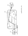
図10は、本実施例1における効果を説明するための図である。端末200から、ユーザトラフィックのパケットを、ノード310、330、340を経由して、サーバ400に送信するとき、キャプチャ端末1は、ノード310を通過するパケットを受信(キャプチャ)する。
FIG. 10 is a diagram for explaining the effect of the first embodiment. When the user traffic packet is transmitted from the terminal 200 to the
そして、キャプチャ端末1は、キャプチャしたパケットから、そのパケットの送信先(又は送信元)を宛て先とするプローブパケットを生成して網に送信する。即ち、端末200からのユーザトラフィックのパケットと、プローブパケットとが略同時にノード310を経由して、順次同じ経路に伝送される。その後キャプチャ端末1は、プローブ応答パケットを受信することで、結果保存DB42に経路が蓄積される。
Then, the capture terminal 1 generates a probe packet addressed to the transmission destination (or transmission source) of the packet from the captured packet and transmits the probe packet to the network. That is, the user traffic packet from the terminal 200 and the probe packet are sequentially transmitted to the same route via the
従って、本実施例1では、経路状態をユーザトラフィックに応じて即時的に取得することが可能となる。また、キャプチャ端末1を操作する網オペレータがプローブパケットを生成するためのトリガとなる操作を別途行う必要がない。よって、経路状態を即時的に取得できるため、障害発生時点での経路状態も即時取得できる。 Therefore, in the first embodiment, the path state can be acquired immediately according to user traffic. Further, it is not necessary for the network operator who operates the capture terminal 1 to separately perform an operation that becomes a trigger for generating the probe packet. Therefore, since the route state can be acquired immediately, the route state at the time of occurrence of the failure can also be acquired immediately.
上述した例では、キャプチャ端末1を備えるネットワークシステム100の例で説明したが、例えば、ユーザが使用する端末210に、上述したキャプチャ端末1の機能を備えるようにしてもよい。図11は、そのような場合のネットワークシステム100の構成例を示す図である。 In the example described above, the example of the network system 100 including the capture terminal 1 has been described. For example, the terminal 210 used by the user may be provided with the function of the capture terminal 1 described above. FIG. 11 is a diagram illustrating a configuration example of the network system 100 in such a case.
この場合、端末210は、網を流れる多数のユーザのトラフィックをキャプチャするのではなく、ユーザ自身が(端末210自身が)送受信するトラフィックを対象としてキャプチャする。 In this case, the terminal 210 does not capture the traffic of a large number of users flowing through the network, but captures traffic that the user himself / herself (the terminal 210 itself) transmits / receives.
また、プローブパケットは、ユーザトラフィックの宛て先アドレスにのみ送信される。ユーザトラフィックの送信元アドレスは端末210のアドレスのため、例えば図6(B)のようなプローブパケットは生成されず、送信されない。 The probe packet is transmitted only to the destination address of the user traffic. Since the source address of the user traffic is the address of the terminal 210, for example, a probe packet as shown in FIG. 6B is not generated and transmitted.
更に、結果保存DB42に蓄積される経路情報は、ユーザがアクセスした先(ユーザトラフィックの宛て先アドレスを持つサーバ400など)に関するものとなる。
Further, the route information stored in the
この場合でも、上述した例と同様に経路状態を即時取得可能で、障害発生時点での経路状態も取得可能である。 Even in this case, the route state can be acquired immediately as in the above-described example, and the route state at the time of occurrence of the failure can also be acquired.
次に実施例2について説明する。本実施例2は、以前に保存した経路情報と、新たに抽出した経路情報とを比較し、変動があればその旨を網オペレータやユーザに通知するようにした例である。 Next, Example 2 will be described. The second embodiment is an example in which previously stored route information is compared with newly extracted route information, and if there is a change, this is notified to the network operator or user.
図12は、本実施例2において適用されるキャプチャ端末1の構成例である。実施例1のキャプチャ端末1と同一の構成部分には同一の符号を付している。異なるのは、プローブ受信部40において、結果比較部43と差分データベース(DB)44とを更に備える点である。
FIG. 12 is a configuration example of the capture terminal 1 applied in the second embodiment. The same components as those of the capture terminal 1 of the first embodiment are denoted by the same reference numerals. The difference is that the
結果保存部41により結果保存DB42が構築されるまでは実施例1と同様である。結果保存機能の処理(図8)が終了した後、結果比較機能を実行するための処理が開示され、経路の変動が網オペレータやユーザに通知される。図13は、結果比較機能を実行するためのフローチャートの例である。
The process is the same as in the first embodiment until the
結果比較部43は、結果比較機能を実行するための処理を開始すると(S50)、以前の結果比較処理でメモリに展開された結果(後述)を差分DB44に記録する(S51)。そして、結果保存機能の処理(図8)と同様に、結果保存部41は受信したパケット(プローブパケット又はプローブ応答パケット)に対してメモリに結果保存DB42と同様のエントリの作成等を行う。メモリに記憶されたエントリは、その後、差分DB44と比較することで経路の比較に用いられる。
When the
次いで、結果比較部43は、パケットが最終応答パケットか否かを判断する(S52)。即ち、受信したパケット(プローブパケット又はプローブ応答パケット)が最終ホップ目の宛て先(Dst)アドレスに対する応答パケットか否かを判断する。
Next, the
これは、受信パケットの送信元アドレスが、差分DB44のエントリにあるプローブパケットの宛て先(Dst)アドレスと同一か否かにより判断する。或いは、プローブパケットを受信した各ノード310〜370等は、プローブパケットをプローブ応答パケットのペイロード557に格納しているため(図7(A)及び同図(B)参照)、ペイロード557に格納されたプローブパケットの宛て先アドレスを参照して、差分DB44のエントリと比較するようにしてもよい。又は、受信パケットのTTLフィールド536、556に格納された値が、例えば「5」(ホップ数として最初に設定した値)であれば、最終応答パケットと判断してもよい。
This is determined by whether or not the source address of the received packet is the same as the destination (Dst) address of the probe packet in the entry of the
受信したパケットが最終応答パケットではないとき(S52で「最終応答パケットではない」)、結果比較処理は終了する(S56)。これは、最終パケットを受信するまでは、同一エントリ内のサブエントリや要素が全て構築されておらず、その後の処理で経路の比較を行うことができないからである。 When the received packet is not the final response packet (“not final response packet” in S52), the result comparison process ends (S56). This is because all the subentries and elements in the same entry are not constructed until the final packet is received, and the path comparison cannot be performed in the subsequent processing.
一方、受信パケットが最終応答パケットのとき(S52で、「最終応答パケット」)、経路の比較作業を実際に行うことになる。まず、結果比較部43は差分DB44を参照し、メモリに記憶されたエントリのうち宛て先(Dst)アドレスと同一のエントリが差分DB44に存在するか否かを判断する(S53)。過去に同一経路について経路の比較調査を行ったか否かを判断するためである。
On the other hand, when the received packet is the final response packet (“final response packet” in S52), the path comparison operation is actually performed. First, the
同じ宛て先(Dst)アドレスのエントリが差分DB44に存在しないとき(S53で「存在しない」)、処理は終了する(S57)。その経路については始めて調査することになるため差分は抽出することはできないからである。 When no entry with the same destination (Dst) address exists in the difference DB 44 (“does not exist” in S53), the process ends (S57). This is because the difference cannot be extracted because the route will be investigated for the first time.
一方、同じ宛て先(Dst)アドレスのエントリが差分DB44に存在するとき(S53で「存在する」)、結果比較部43は、差分DB44の内容(エントリ内のシーケンス値カウンタやSrcアドレス等)とメモリに記憶された内容を全て比較して、差分DB44の内容が一致するか否か判断する(S54)。
On the other hand, when an entry with the same destination (Dst) address exists in the difference DB 44 ("exists" in S53), the
一つでも内容が異なれば(S54で「一致しない」)、結果比較部43は経路に差異が存在することになるため、変動があった旨を網オペレータ又はユーザに通知する(S58)。
If even one content is different (“does not match” in S54), the
通知は、例えば、結果比較部43が変動があった旨をモニタ等の表示部に表示させるようにしてもよいし、メモリ等に発生時間とともに記憶してログを取るようにしてもよい。
The notification may be, for example, displayed on the display unit such as a monitor that the
一方、差異がないとき(S54で「一致する」)、又は差異があって変動があった旨を通知した後、結果比較部43は差分DB44の既存エントリを削除して終了する(S55)。この処理と、上述のメモリに展開された結果の差分DB44への記録(S51)により、常に、新しい結果が差分DB44に保存されることになる。
On the other hand, when there is no difference (“matches” in S54), or after notifying that there is a difference and there is a change, the
このように、本実施例2では、ある時点で突然経路の変動が生じた場合、差分DB44の内容とメモリに記憶された内容とが一致しなくなり、その旨が網オペレータやユーザに通知されるため、経路の変動を網オペレータ等が把握することができる。
As described above, in the second embodiment, when a path change suddenly occurs at a certain point in time, the contents of the
尚、結果比較機能の処理が実行される前までは、実施例1と同様の処理が実行されるため、本実施例2においても実施例1と同様の作用効果を奏する。 In addition, since the process similar to Example 1 is performed before the process of a result comparison function is performed, also in this Example 2, there exists an effect similar to Example 1. FIG.
上述した例において、結果比較部43は差分DB44のすべての内容を比較するようにしたが(図13のS54)、例えば、比較対象をサブエントリの要素のみを比較するようにしてもよい。図9の例では、要素431〜435、451のみ比較するようにしてもよい。差分DB44(結果保存DB42と同一の構成)のサブエントリ421〜425、441〜442、461は、経路が変動してもしなくても、その内容に変化はなく、経路に変動があったとき、プローブ応答パケットの送信元(Src)アドレスが変化するからである。この場合、結果比較部43は、すべての内容を比較していないため、その分処理を早くすることができる。勿論、上述した例と同様の作用効果も奏する。
In the example described above, the
次に実施例3について説明する。本実施例3は、重複したプローブパケットの送信を防止し、網に対する調査を低負荷で行い得るようにした例である。 Next, Example 3 will be described. The third embodiment is an example in which duplicate probe packets are prevented from being transmitted and the network can be investigated with a low load.
図2において、パケット生成部31は、アドレス抽出部21から抽出されたアドレスが入力される度にプローブパケットを生成することになる。以前に送信した同じアドレスに対して、プローブパケットを重複して生成し、網に送信することもある。
In FIG. 2, the
そこで、本実施例3では、同じアドレスにプローブパケットを送信するような、重複したプローブパケットの送信を防止するようにしている。 Therefore, in the third embodiment, transmission of duplicate probe packets, such as transmitting probe packets to the same address, is prevented.
図14は、本実施例3におけるキャプチャ端末1の構成例を示す図である。実施例1(図2)と異なるのは、ユーザトラフィック抽出部20において、ユーザトラフィックテーブル22とタイムアウト部23とを備える点である。
FIG. 14 is a diagram illustrating a configuration example of the capture terminal 1 according to the third embodiment. The difference from the first embodiment (FIG. 2) is that the user
ユーザトラフィックテーブル22は、アドレス抽出部21により抽出された送信元(Src)アドレスと宛て先(Dst)アドレスとの組が記憶される。
The user traffic table 22 stores a set of a transmission source (Src) address and a destination (Dst) address extracted by the
また、タイムアウト部23は、網オペレータ等により設定された時間が経過すると、ユーザトラフィックテーブル22に記憶されたエントリを削除する。
Further, the
図15は、重複プローブ防止機能を実行するための処理の動作を示すフローチャートの例である。タイムアウトの処理も付加されている。 FIG. 15 is an example of a flowchart showing an operation of processing for executing the duplicate probe prevention function. A timeout process is also added.
アドレス抽出部21は、アドレス抽出機能を実行する処理を開始すると(S60)、ユーザトラフィックのパケットから送信元(Src)アドレスと、宛て先(Dst)アドレスとを抽出する(S61)。実施例1と同様である。
When starting the process of executing the address extraction function (S60), the
次いで、アドレス抽出部21は、ユーザトラフィックテーブル22を参照して、アドレスの組によるエントリが存在するか否か判断する(S62)。
Next, the
ユーザトラフィックテーブル22には、以前にプローブパケットを送信したアドレスの組が記憶されている。従って、アドレス抽出部21が、例えば、宛て先アドレスをキーにして検索し、マッチするアドレスが存在すれば以前にプローブパケットを送信したことを意味することになる。
The user traffic table 22 stores a set of addresses that have previously transmitted probe packets. Therefore, for example, the
よって、ユーザトラフィックテーブル22にエントリが存在すれば(S62で「エントリ存在する」)、アドレス抽出部21はパケットを破棄して処理を終了させる(S63)。この場合、パケット生成部31に各アドレスが出力されないため、プローブパケットは生成されない。
Therefore, if there is an entry in the user traffic table 22 (“entry exists” in S62), the
一方、ユーザトラフィックテーブル22にエントリが存在しなければ(S62で「エントリ存在しない」)、アドレス抽出部21は、ユーザトラフィックテーブル22に対して、送信元(Src)と宛て先(Dst)のアドレスの組である新たなエントリを作成する(S64)。このとき、アドレス抽出部21は、テーブル22にエントリを作成した時間(タイムスタンプ)も同時に記憶する。
On the other hand, if there is no entry in the user traffic table 22 (“entry does not exist” in S62), the
そして、アドレス抽出部21は各アドレスをパケット生成部31に出力し、プローブパケットが生成される。その後の処理は実施例1と同様である。
Then, the
また、タイムアウト部23では、予め網オペレータ等が設定した時間(n分:例えば、メモリに記憶されたタイムアウト時間)から、エントリの「タイムスタンプ」が現在よりn分前か否かを判断する(S71)。つまり、タイムアウト部23は「タイムスタンプ」の時間から、「タイムアウト時間」経過したか否かを判断する。勿論、タイムアウト時間は「分」単位ではなく、「秒」単位でもよい。
Further, the time-out
設定したタイムアウト時間経過したとき(S71で「はい」)、タイムアウト部23はユーザトラフィックテーブル22の該当エントリを削除する(S72)。これにより、ユーザトラフィックテーブル22のエントリが増大するのを防止できる。
When the set timeout period elapses (“Yes” in S71), the
一方、決定したタイムアウト時間経過していないとき(S71で「いいえ」)、又は該当エントリ削除後、タイムアウト部23はテーブル22内の全エントリを走査し(S73)、常にタイムアウト時間経過したか否か調査することになる。
On the other hand, when the determined timeout time has not elapsed (“No” in S71) or after the corresponding entry is deleted, the
一定時間経過してもパケットを網に送信し続けるトラフィックに対しては、エントリが削除された後、再度、エントリがテーブル22内に作成されるため、プローブパケットの送信は継続することができる。 For traffic that continues to send packets to the network even after a certain period of time, the entry is created again in the table 22 after the entry is deleted, so that transmission of the probe packet can be continued.
このように、本実施例3では、ユーザトラフィックテーブル22に同一のアドレスが記憶されていれば、プローブパケットが生成、送信されないため、重複したプローブパケットの送信を防止することができ、網に対して低負荷で実施例1と同様の調査を行うことができる。 As described above, in the third embodiment, if the same address is stored in the user traffic table 22, probe packets are not generated and transmitted, so that transmission of duplicate probe packets can be prevented. Thus, the same investigation as in Example 1 can be performed with a low load.
また、この際にユーザトラフィックテーブル22に対して一定時間経過後、該当エントリを削除してエントリの増大を防ぐとともに、一定時間経過しても通信が継続するトラフィックに対しては継続調査を行うこともできる。 At this time, after a certain period of time has elapsed with respect to the user traffic table 22, the corresponding entry is deleted to prevent the number of entries from increasing, and a continuous investigation is performed for traffic that continues to be communicated even after a certain period of time has elapsed. You can also.
尚、本実施例3は、上述した実施例2においても実施可能であり、実施例2と同様の作用効果を奏する。 In addition, this Example 3 can be implemented also in Example 2 mentioned above, and there exists an effect similar to Example 2. FIG.
以上まとめると付記のようになる。 The above is summarized as an appendix.
(付記1)
網の経路状態を調査する管理装置において、
前記網からのトラフィックを受信するパケット送受信部と、
受信した前記トラフィックから、アドレス情報を抽出するアドレス抽出部と、
抽出された前記アドレス情報を送信先とするプローブパケットを生成するプローブパケット生成部とを備え、
前記パケット送受信部は、生成された前記プローブパケットを前記網に送信するとともに、前記トラフィックが転送される前記網の経路に沿って送信された前記プローブパケットに対するプローブ応答パケットを受信することを特徴とする管理装置。
(Appendix 1)
In the management device that investigates the route status of the network,
A packet transceiver for receiving traffic from the network;
An address extraction unit that extracts address information from the received traffic;
A probe packet generation unit that generates a probe packet having the extracted address information as a transmission destination,
The packet transmission / reception unit transmits the generated probe packet to the network and receives a probe response packet for the probe packet transmitted along the network path to which the traffic is transferred. Management device.
(付記2)
更に、前記プローブ応答パケットから経路情報を作成し、前記経路情報を保存する結果保存部を備えることを特徴する付記1記載の管理装置。
(Appendix 2)
The management apparatus according to appendix 1, further comprising a result storage unit that generates route information from the probe response packet and stores the route information.
(付記3)
前記結果保存部は、保存した第1の経路情報と、新たに受信した前記プローブ応答パケットから作成した第2の経路情報とを比較することで、前記網に転送される前記トラフィックの経路の変動を検出することを特徴とする付記2記載の管理装置。
(Appendix 3)
The result storage unit compares the stored first route information with the second route information created from the newly received probe response packet, thereby changing the route of the traffic transferred to the network. The management device according to appendix 2, wherein the management device is detected.
(付記4)
前記ユーザトラフィック抽出部は、抽出した前記アドレス情報を保存し、新たに受信した前記トラフィックから抽出した前記アドレス情報と同一のときは、前記プローブパケット生成部に対し前記プローブパケットを生成させないようにすることを特徴とする付記1記載の管理装置。
(Appendix 4)
The user traffic extraction unit stores the extracted address information, and prevents the probe packet generation unit from generating the probe packet when the address information is the same as the address information extracted from the newly received traffic. The management device according to supplementary note 1, wherein:
(付記5)
前記ユーザトラフィック抽出部は、保存した前記アドレス情報を一定時間経過後消去することを特徴とする付記4記載の管理装置。
(Appendix 5)
The management apparatus according to appendix 4, wherein the user traffic extraction unit deletes the stored address information after a predetermined time has elapsed.
(付記6)
前記パケット送受信部は、前記プローブ応答パケットを受信するともに、前記網に転送されずループバック機能により前記プローブパケットを受信し、
前記結果保存部は、前記プローブ応答パケットと、前記ループバック機能により受信した前記プローブパケットとから前記経路情報を作成することを特徴とする付記2記載の管理装置。
(Appendix 6)
The packet transmission / reception unit receives the probe response packet, receives the probe packet by a loopback function without being transferred to the network,
The management apparatus according to appendix 2, wherein the result storage unit creates the route information from the probe response packet and the probe packet received by the loopback function.
(付記7)
前記プローブパケット生成部は、抽出された前記アドレス情報に対して、予め設定されたホップ数分の前記プローブパケットを生成することを特徴とする付記1記載の管理装置。
(Appendix 7)
The management apparatus according to claim 1, wherein the probe packet generation unit generates the probe packets for a preset number of hops with respect to the extracted address information.
(付記8)
前記プローブパケット生成部は、前記プローブパケットごとに異なる識別子を、生成された前記プローブパケットに付加することを特徴とする付記1記載の管理装置。
(Appendix 8)
The management device according to claim 1, wherein the probe packet generation unit adds an identifier that is different for each probe packet to the generated probe packet.
(付記9)
前記識別子は、前記プローブパケットの送信先であるターゲットごとにユニークなシーケンス番号と、送信される前記プローブパケットのホップ数を示す値とを含むことを特徴とする付記8記載の管理装置。
(Appendix 9)
9. The management apparatus according to appendix 8, wherein the identifier includes a sequence number that is unique for each target that is a transmission destination of the probe packet, and a value that indicates a hop number of the probe packet to be transmitted.
(付記10)
前記結果保存部は、前記シーケンス番号が同一の前記プローブ応答パケットを同一エントリ内にまとめて保存することを特徴とする付記9記載の管理装置。
(Appendix 10)
The management apparatus according to appendix 9, wherein the result storage unit stores the probe response packets having the same sequence number together in the same entry.
(付記11)
前記プローブ応答パケットには前記プローブパケットの送信された前記ターゲットのアドレス情報が含まれ、前記結果保存部には前記アドレス情報が前記エントリ内に含まれることを特徴とする付記10記載の管理装置。
(Appendix 11)
11. The management apparatus according to
(付記12)
網の経路状態を調査する管理方法において、
前記網からのトラフィックを受信し、
受信した前記トラフィックから、アドレス情報を抽出し、
抽出された前記アドレス情報を送信先とするプローブパケットを生成し、
生成された前記プローブパケットを前記網に送信するとともに、前記トラフィックが転送される前記網の経路に沿って送信された前記プローブパケットに対するプローブ応答パケットを受信することを特徴とする管理方法。
(Appendix 12)
In the management method to investigate the route status of the network,
Receive traffic from the network,
Extract address information from the received traffic,
Generate a probe packet whose destination is the extracted address information,
A management method for transmitting the generated probe packet to the network and receiving a probe response packet for the probe packet transmitted along the route of the network to which the traffic is transferred.
(付記13)
網の経路状態を調査する管理プログラムにおいて、
前記網からのトラフィックを受信する処理と、
受信した前記トラフィックから、アドレス情報を抽出する処理と、
抽出された前記アドレス情報を送信先とするプローブパケットを生成する処理と、
生成された前記プローブパケットを前記網に送信するとともに、前記トラフィックが転送される前記網の経路に沿って送信された前記プローブパケットに対するプローブ応答パケットを受信する処理と、
をコンピュータに実行させることを特徴とする管理プログラム。
(Appendix 13)
In the management program that investigates the route status of the network,
Processing to receive traffic from the network;
A process of extracting address information from the received traffic;
A process of generating a probe packet having the extracted address information as a transmission destination;
A process of transmitting the generated probe packet to the network and receiving a probe response packet for the probe packet transmitted along the path of the network to which the traffic is transferred;
A management program for causing a computer to execute.
(付記14)
端末とサーバとが網を介して接続されるとともに、網の経路状態を調査する管理装置が前記網に接続された網システムにおいて、
前記管理装置には、
前記端末から前記サーバに転送されるトラフィックを受信するパケット送受信部と、
受信した前記トラフィックから、アドレス情報を抽出するアドレス抽出部と、
抽出された前記アドレス情報を送信先とするプローブパケットを生成するプローブパケット生成部とを備え、
前記パケット送受信部は、生成された前記プローブパケットを前記網に送信するとともに、前記トラフィックが転送される前記網の経路に沿って送信された前記プローブパケットに対するプローブ応答パケットを受信することを特徴とする網システム。
(Appendix 14)
In a network system in which a terminal and a server are connected via a network, and a management device that investigates a route state of the network is connected to the network,
In the management device,
A packet transmission / reception unit for receiving traffic transferred from the terminal to the server;
An address extraction unit that extracts address information from the received traffic;
A probe packet generation unit that generates a probe packet having the extracted address information as a transmission destination,
The packet transmission / reception unit transmits the generated probe packet to the network and receives a probe response packet for the probe packet transmitted along the network path to which the traffic is transferred. Network system to do.
1 キャプチャ/プローブ端末
10 パケット送受信部
11 パケット受信部
12 振り分け部
13 パケット送信部
20 ユーザトラフィック抽出部
21 アドレス抽出部
22 ユーザトラフィックテーブル
23 タイムアウト部
30 プローブパケット生成部
31 パケット生成部
32 ターゲット定義テーブル
33 シーケンス値カウンタ
40 プローブ受信部
41 結果保存部
42 結果保存データベース(結果保存DB)
43 結果比較部
44 差分データベース(差分DB)
200、210 端末
300 IPネットワーク
310〜370 ノード
400 サーバ
500 IPパケット
530 プローブパケット
550 プローブ応答パケット
421〜425、441〜442、461 サブエントリ
431〜435、451 サブエントリの要素
1 Capture /
11
43
200, 210
Claims (8)
前記網からのトラフィックを受信するパケット送受信部と、
受信した前記トラフィックから、アドレス情報を抽出するアドレス抽出部と、
抽出された前記アドレス情報を送信先とするプローブパケットを生成するプローブパケット生成部とを備え、
前記パケット送受信部は、生成された前記プローブパケットを前記網に送信するとともに、前記プローブパケットに対するプローブ応答パケットを受信し、
前記プローブパケット生成部は、抽出された前記アドレス情報を送信先とする前記プローブパケットに対して予め設定されたホップ数分の前記プローブパケットを生成し、更に、前記プローブパケットごとに異なる識別子を前記プローブパケットに付加することを特徴とする管理装置。 In the management device that investigates the route status of the network,
A packet transceiver for receiving traffic from the network;
An address extraction unit that extracts address information from the received traffic;
A probe packet generation unit that generates a probe packet having the extracted address information as a transmission destination,
Wherein the packet transceiver unit, the generated the probe packet and transmits to the network, and receives a probe response packet to the previous SL probe packet,
The probe packet generation unit generates the probe packet for the number of hops set in advance for the probe packet having the extracted address information as a transmission destination, and further, a different identifier for each probe packet. A management apparatus characterized by being added to a probe packet.
前記網からのトラフィックを受信し、
受信した前記トラフィックから、アドレス情報を抽出し、
抽出された前記アドレス情報を送信先とするプローブパケットを生成し、
生成された前記プローブパケットを前記網に送信するとともに、前記プローブパケットに対するプローブ応答パケットを受信し、
前記プローブパケットを生成するとき、抽出された前記アドレス情報を送信先とする前記プローブパケットに対して予め設定されたホップ数分の前記プローブパケットを生成し、更に、前記プローブパケットごとに異なる識別子を前記プローブパケットに付加することを特徴とする管理方法。 In the management method to investigate the route status of the network,
Receive traffic from the network,
Extract address information from the received traffic,
Generate a probe packet whose destination is the extracted address information,
The generated said probe packet and transmits to the network, and receives a probe response packet to the previous SL probe packet,
When generating the probe packet, the probe packet is generated for the preset number of hops with respect to the probe packet having the extracted address information as a transmission destination, and a different identifier for each probe packet is generated. A management method comprising adding to the probe packet.
前記網からのトラフィックを受信する処理と、
受信した前記トラフィックから、アドレス情報を抽出する処理と、
抽出された前記アドレス情報を送信先とするプローブパケットを生成する処理と、
生成された前記プローブパケットを前記網に送信するとともに、前記プローブパケットに対するプローブ応答パケットを受信する処理と、
をコンピュータに実行させ、
前記プローブパケットを生成する処理において、抽出された前記アドレス情報を送信先とする前記プローブパケットに対して予め設定されたホップ数分の前記プローブパケットを生成し、更に、前記プローブパケットごとに異なる識別子を前記プローブパケットに付加する処理を前記コンピュータに実行させることを特徴とする管理プログラム。 In the management program that investigates the route status of the network,
Processing to receive traffic from the network;
A process of extracting address information from the received traffic;
A process of generating a probe packet having the extracted address information as a transmission destination;
The product is the probe packet was transmits to the network, a process of receiving a probe response packet to the previous SL probe packet,
To the computer,
In the process of generating the probe packet, the probe packet is generated for the number of hops set in advance for the probe packet having the extracted address information as a transmission destination, and an identifier different for each probe packet. A management program for causing the computer to execute a process of adding to the probe packet.
前記管理装置には、
前記端末から前記サーバに転送されるトラフィックを受信するパケット送受信部と、
受信した前記トラフィックから、アドレス情報を抽出するアドレス抽出部と、
抽出された前記アドレス情報を送信先とするプローブパケットを生成するプローブパケット生成部とを備え、
前記パケット送受信部は、生成された前記プローブパケットを前記網に送信するとともに、前記プローブパケットに対するプローブ応答パケットを受信し、
前記プローブパケット生成部は、抽出された前記アドレス情報を送信先とする前記プローブパケットに対して予め設定されたホップ数分の前記プローブパケットを生成し、更に、前記プローブパケットごとに異なる識別子を前記プローブパケットに付加するすることを特徴とする網システム。 In a network system in which a terminal and a server are connected via a network, and a management device that investigates a route state of the network is connected to the network,
In the management device,
A packet transmission / reception unit for receiving traffic transferred from the terminal to the server;
An address extraction unit that extracts address information from the received traffic;
A probe packet generation unit that generates a probe packet having the extracted address information as a transmission destination,
Wherein the packet transceiver unit, the generated the probe packet and transmits to the network, and receives a probe response packet to the previous SL probe packet,
The probe packet generation unit generates the probe packet for the number of hops set in advance for the probe packet having the extracted address information as a transmission destination, and further assigns a different identifier for each probe packet. A network system that is added to a probe packet.
Priority Applications (2)
| Application Number | Priority Date | Filing Date | Title |
|---|---|---|---|
| JP2006155724A JP4910488B2 (en) | 2006-06-05 | 2006-06-05 | Management device and network system for investigating network path status |
| US11/585,285 US8254388B2 (en) | 2006-06-05 | 2006-10-24 | Management device to investigate path states of network and network system |
Applications Claiming Priority (1)
| Application Number | Priority Date | Filing Date | Title |
|---|---|---|---|
| JP2006155724A JP4910488B2 (en) | 2006-06-05 | 2006-06-05 | Management device and network system for investigating network path status |
Publications (2)
| Publication Number | Publication Date |
|---|---|
| JP2007325154A JP2007325154A (en) | 2007-12-13 |
| JP4910488B2 true JP4910488B2 (en) | 2012-04-04 |
Family
ID=38790072
Family Applications (1)
| Application Number | Title | Priority Date | Filing Date |
|---|---|---|---|
| JP2006155724A Expired - Fee Related JP4910488B2 (en) | 2006-06-05 | 2006-06-05 | Management device and network system for investigating network path status |
Country Status (2)
| Country | Link |
|---|---|
| US (1) | US8254388B2 (en) |
| JP (1) | JP4910488B2 (en) |
Families Citing this family (13)
| Publication number | Priority date | Publication date | Assignee | Title |
|---|---|---|---|---|
| US20080205388A1 (en) * | 2007-02-22 | 2008-08-28 | Microsoft Corporation | Discovery of network devices logically located between a client and a service |
| US8380894B2 (en) * | 2009-12-11 | 2013-02-19 | International Business Machines Corporation | I/O mapping-path tracking in a storage configuration |
| WO2013057773A1 (en) * | 2011-10-17 | 2013-04-25 | 富士通株式会社 | Program, information processing device, and path setting method |
| US9774516B2 (en) * | 2012-09-06 | 2017-09-26 | Unisys Corporation | Trace route command execution from a virtualized environment |
| US9274916B2 (en) | 2013-06-12 | 2016-03-01 | International Business Machines Corporation | Unit attention processing in proxy and owner storage systems |
| US8819317B1 (en) | 2013-06-12 | 2014-08-26 | International Business Machines Corporation | Processing input/output requests using proxy and owner storage systems |
| US9274989B2 (en) | 2013-06-12 | 2016-03-01 | International Business Machines Corporation | Impersonating SCSI ports through an intermediate proxy |
| US9779003B2 (en) | 2013-06-12 | 2017-10-03 | International Business Machines Corporation | Safely mapping and unmapping host SCSI volumes |
| US9769062B2 (en) | 2013-06-12 | 2017-09-19 | International Business Machines Corporation | Load balancing input/output operations between two computers |
| US9940019B2 (en) | 2013-06-12 | 2018-04-10 | International Business Machines Corporation | Online migration of a logical volume between storage systems |
| US10892976B2 (en) | 2017-10-24 | 2021-01-12 | Keysight Technologies, Inc. | Methods, systems, and computer readable media for intelligent network topology mapping |
| CN112994748A (en) * | 2021-02-03 | 2021-06-18 | 青岛鼎信通讯股份有限公司 | Medium-voltage carrier-based configuration-free path detection method |
| US11665079B1 (en) * | 2022-05-16 | 2023-05-30 | Cisco Technology, Inc. | Probe-triggered full device state capture, export, and correlation |
Family Cites Families (9)
| Publication number | Priority date | Publication date | Assignee | Title |
|---|---|---|---|---|
| US6510461B1 (en) * | 1997-06-30 | 2003-01-21 | Sun Microsystems, Inc. | System for managing and automatically deleting network address identified and stored during a network communication session when the network address is visited |
| JP2000244563A (en) | 1999-02-18 | 2000-09-08 | Fujitsu Ltd | Route tracing method and network system using this |
| US6826172B1 (en) * | 2000-06-09 | 2004-11-30 | Steven Augart | Network probing using overlapping probe packets |
| US20030161265A1 (en) * | 2002-02-25 | 2003-08-28 | Jingjun Cao | System for end user monitoring of network service conditions across heterogeneous networks |
| US7260645B2 (en) * | 2002-04-26 | 2007-08-21 | Proficient Networks, Inc. | Methods, apparatuses and systems facilitating determination of network path metrics |
| JP4232550B2 (en) | 2002-07-01 | 2009-03-04 | 日本電気株式会社 | Network information detection apparatus and method |
| US7760663B2 (en) | 2004-04-19 | 2010-07-20 | Jds Uniphase Corporation | Packet tracing using dynamic packet filters |
| US7619982B2 (en) * | 2005-04-25 | 2009-11-17 | Cisco Technology, Inc. | Active probe path management |
| JP2007324642A (en) * | 2006-05-30 | 2007-12-13 | Matsushita Electric Ind Co Ltd | Information processing system, information processing apparatus, server and information processing method |
-
2006
- 2006-06-05 JP JP2006155724A patent/JP4910488B2/en not_active Expired - Fee Related
- 2006-10-24 US US11/585,285 patent/US8254388B2/en not_active Expired - Fee Related
Also Published As
| Publication number | Publication date |
|---|---|
| US20070280244A1 (en) | 2007-12-06 |
| US8254388B2 (en) | 2012-08-28 |
| JP2007325154A (en) | 2007-12-13 |
Similar Documents
| Publication | Publication Date | Title |
|---|---|---|
| JP4910488B2 (en) | Management device and network system for investigating network path status | |
| JP3947146B2 (en) | Routing loop detection program and routing loop detection method | |
| Mahajan et al. | User-level Internet path diagnosis | |
| US7698460B2 (en) | Peer-to-peer method of quality of service (QoS) probing and analysis and infrastructure employing same | |
| US7876675B2 (en) | Multicast network monitoring method and multicast network system to which the method is applied | |
| Vanaubel et al. | Network fingerprinting: TTL-based router signatures | |
| JP4764810B2 (en) | Abnormal traffic monitoring device, entry management device, and network system | |
| CN101247321A (en) | Method, device and system for routing diagnosis in network based on diameter protocol | |
| EP1706959A2 (en) | Detection of forwarding problems for external prefixes | |
| JPWO2009040903A1 (en) | Network monitoring system, route extraction method, program, and computer-readable recording medium recording the program | |
| JP5593944B2 (en) | Determination apparatus, determination method, and computer program | |
| JP2005285040A (en) | Network monitoring system, method and program | |
| US8559317B2 (en) | Alarm threshold for BGP flapping detection | |
| JP2017118438A (en) | Packet transmission program, information processing device and failure detection method | |
| WO2009038384A1 (en) | Query processing system and methods for a database with packet information by dividing a table and query | |
| CN101702712A (en) | Detection technology and voice call backup linkage method and device thereof | |
| CN108809678A (en) | A kind of method and server of information push | |
| US10333817B2 (en) | Non-transitory computer-readable storage medium, communication device, and determination method | |
| CN113596037B (en) | APT attack detection method based on event relation directed graph in network full flow | |
| CN105025028B (en) | The black holes IP based on flow analysis find method | |
| US20090129267A1 (en) | System and method for discovering sctp associations in a network | |
| Vacirca et al. | An algorithm to detect TCP spurious timeouts and its application to operational UMTS/GPRS networks | |
| JP2016015676A (en) | Monitoring device, monitoring system, and monitoring method | |
| JP4235907B2 (en) | Worm propagation monitoring system | |
| JP2010219951A (en) | Repeating method, transmitting apparatus, receiving device, and relay apparatus |
Legal Events
| Date | Code | Title | Description |
|---|---|---|---|
| A621 | Written request for application examination |
Free format text: JAPANESE INTERMEDIATE CODE: A621 Effective date: 20090309 |
|
| A977 | Report on retrieval |
Free format text: JAPANESE INTERMEDIATE CODE: A971007 Effective date: 20110117 |
|
| A131 | Notification of reasons for refusal |
Free format text: JAPANESE INTERMEDIATE CODE: A131 Effective date: 20110208 |
|
| A521 | Request for written amendment filed |
Free format text: JAPANESE INTERMEDIATE CODE: A523 Effective date: 20110411 |
|
| A131 | Notification of reasons for refusal |
Free format text: JAPANESE INTERMEDIATE CODE: A131 Effective date: 20110802 |
|
| A521 | Request for written amendment filed |
Free format text: JAPANESE INTERMEDIATE CODE: A523 Effective date: 20110930 |
|
| TRDD | Decision of grant or rejection written | ||
| A01 | Written decision to grant a patent or to grant a registration (utility model) |
Free format text: JAPANESE INTERMEDIATE CODE: A01 Effective date: 20111220 |
|
| A01 | Written decision to grant a patent or to grant a registration (utility model) |
Free format text: JAPANESE INTERMEDIATE CODE: A01 |
|
| A61 | First payment of annual fees (during grant procedure) |
Free format text: JAPANESE INTERMEDIATE CODE: A61 Effective date: 20120102 |
|
| R150 | Certificate of patent or registration of utility model |
Free format text: JAPANESE INTERMEDIATE CODE: R150 |
|
| FPAY | Renewal fee payment (event date is renewal date of database) |
Free format text: PAYMENT UNTIL: 20150127 Year of fee payment: 3 |
|
| LAPS | Cancellation because of no payment of annual fees |