JP4909030B2 - Collision avoidance support system and vehicle equipped with the same - Google Patents
Collision avoidance support system and vehicle equipped with the same Download PDFInfo
- Publication number
- JP4909030B2 JP4909030B2 JP2006320439A JP2006320439A JP4909030B2 JP 4909030 B2 JP4909030 B2 JP 4909030B2 JP 2006320439 A JP2006320439 A JP 2006320439A JP 2006320439 A JP2006320439 A JP 2006320439A JP 4909030 B2 JP4909030 B2 JP 4909030B2
- Authority
- JP
- Japan
- Prior art keywords
- intervention
- vehicle
- obstacle
- collision avoidance
- support system
- Prior art date
- Legal status (The legal status is an assumption and is not a legal conclusion. Google has not performed a legal analysis and makes no representation as to the accuracy of the status listed.)
- Expired - Fee Related
Links
- 238000012937 correction Methods 0.000 claims description 27
- 238000004891 communication Methods 0.000 claims description 14
- 238000003384 imaging method Methods 0.000 claims description 11
- 230000000903 blocking effect Effects 0.000 claims description 8
- 238000005259 measurement Methods 0.000 claims description 6
- 238000000034 method Methods 0.000 description 10
- 230000003111 delayed effect Effects 0.000 description 6
- 238000012545 processing Methods 0.000 description 5
- 238000010586 diagram Methods 0.000 description 3
- 230000001133 acceleration Effects 0.000 description 2
- 238000000605 extraction Methods 0.000 description 2
- 230000033001 locomotion Effects 0.000 description 2
- 230000005540 biological transmission Effects 0.000 description 1
- 230000015572 biosynthetic process Effects 0.000 description 1
- 238000013461 design Methods 0.000 description 1
- 238000001514 detection method Methods 0.000 description 1
- 230000008014 freezing Effects 0.000 description 1
- 238000007710 freezing Methods 0.000 description 1
- 238000012986 modification Methods 0.000 description 1
- 230000004048 modification Effects 0.000 description 1
- 230000003287 optical effect Effects 0.000 description 1
- 238000003786 synthesis reaction Methods 0.000 description 1
- 210000003462 vein Anatomy 0.000 description 1
Images


Landscapes
- Steering Control In Accordance With Driving Conditions (AREA)
- Control Of Driving Devices And Active Controlling Of Vehicle (AREA)
- Regulating Braking Force (AREA)
- Traffic Control Systems (AREA)
Description
本発明は、車両用の衝突回避支援システムに関し、特に自車両と障害物との横方向距離を考慮することによって、車両運転者の意思によらない自動介入操作を好適に実行する衝突回避支援システムに関する。 The present invention relates to a collision avoidance support system for a vehicle, and in particular, a collision avoidance support system that suitably executes an automatic intervention operation that does not depend on the intention of a vehicle driver by considering the lateral distance between the host vehicle and an obstacle. About.
前方障害物に対して衝突の可能性がある状況において自動的に制動操作等の介入操作を行い衝突を回避する従来の衝突回避支援システムとしては、例えば、衝突の可能性がある場合に警報を発したり或いは車両運転者の意思によらずに自動的に車両を制動させる衝突回避支援システムが知られている(例えば特許文献1参照)。特許文献1に示されている衝突回避支援システムでは障害物までの距離と車速から回避可能な最小制動開始距離が求められ、この最小制動開始距離未満の状況によっても操舵操作が行われた場合は介入制動を開始しないことで不必要な介入制動を抑制し、運転者への違和感を低減している。
As a conventional collision avoidance support system that automatically performs an intervention operation such as a braking operation and avoids a collision in a situation where there is a possibility of a collision with a front obstacle, for example, an alarm is issued when there is a possibility of a collision. There is known a collision avoidance support system that emits or automatically brakes the vehicle regardless of the vehicle driver's intention (see, for example, Patent Document 1). In the collision avoidance support system disclosed in
しかしながら、上記従来技術にあっては、運転者の操舵操作による回避時に介入制動が抑制されることで運転者の違和感は低減されるものの、障害物による進路の占有割合を考慮していないため、操舵が不要な程度の障害物に対して介入制動が起きてしまう可能性があるし、逆に操舵回避が困難な場合でも運転者による操舵操作があれば介入制動を遅らせてしまい、衝突時の速度を十分に低減することができなくなってしまうという問題があった。 However, in the above prior art, although the driver's discomfort is reduced by suppressing the intervention braking when avoiding by the steering operation of the driver, it does not consider the occupation ratio of the route due to the obstacle, Intervention braking may occur for obstacles that do not require steering, and conversely, even if steering avoidance is difficult, intervention braking will be delayed if there is a steering operation by the driver. There was a problem that the speed could not be reduced sufficiently.
本発明は、上記問題に着目してなされたものであり、その目的とするところは、前方障害物との衝突可能性に応じて該障害物との衝突が回避されるように制動操作又は操舵操作もしくは制動操作及び操舵操作によって前方障害物との衝突を回避するように介入制御する衝突回避支援システムにおいて、自車の推定進路内に占める障害物の大きさと障害物との相対速度に基づいて介入開始タイミングを変化させ、安全性を損なうことなく介入操作による運転者に対する違和感を低減することができる衝突回避支援システムを提供することにある。 The present invention has been made paying attention to the above-mentioned problem, and the object of the present invention is to perform a braking operation or steering so that the collision with the obstacle is avoided according to the possibility of the collision with the obstacle in front. In a collision avoidance support system that performs intervention control to avoid a collision with a front obstacle by an operation or a braking operation and a steering operation, based on the size of the obstacle in the estimated course of the host vehicle and the relative speed of the obstacle It is an object of the present invention to provide a collision avoidance support system that can reduce a sense of incongruity to a driver due to an intervention operation without changing the intervention start timing and without impairing safety.
上記の目的を達成するため、本発明の衝突回避支援システムは、前方障害物との衝突の可能性に応じて車両の制動操作又は操舵操作もしくは制動操作及び操舵操作によって前方障害物との衝突を回避するように介入制御する衝突回避支援システムであって、前方障害物との距離情報と前方障害物と自車との相対速度情報とから前記介入制御を開始する介入予定タイミングを算出する介入タイミング算出手段と、自車の走行する予定進路にある前方障害物の横方向の大きさと位置情報から前方障害物が自車の推定進路内を塞ぐ大きさを算出する進路余裕度算出手段と、前記進路余裕度算出手段で算出した推定進路内を塞ぐ大きさによって前記介入予定タイミングを補正して介入開始タイミングを決定する介入タイミング補正手段と、を備えると共に、前記進路余裕度算出手段は、道路上の白線を基準とした前方障害物の位置と大きさを算出するとともに、前記白線を基準とした自車の推定進路を推定し、前方障害物の位置及び大きさと自車の前記推定進路とに基づいて前方障害物が自車の推定進路内を塞ぐ大きさを算出し、前記介入タイミング補正手段は、前記前方障害物が自車の推定進路内を塞ぐ大きさと障害物と自車との相対速度に基づいて制動操作による介入制御か操舵操作による介入制御かを選択することを特徴としている。 In order to achieve the above object, the collision avoidance support system of the present invention performs a collision with a front obstacle by a braking operation or a steering operation or a braking operation and a steering operation of the vehicle according to the possibility of a collision with the front obstacle. A collision avoidance support system for performing intervention control so as to avoid, an intervention timing for calculating a planned intervention timing for starting the intervention control from distance information with a front obstacle and relative speed information between the front obstacle and the vehicle. A calculation means; a course margin calculation means for calculating a size in which the front obstacle covers the estimated course of the own vehicle from the lateral size and position information of the forward obstacle on the planned course on which the host vehicle is traveling; and and intervening timing correction means for determining intervention start timing by correcting the intervention planned timing by the size for closing the interior of the estimated path calculated by the path margin calculation means, when provided with In addition, the course margin calculation means calculates the position and size of the front obstacle based on the white line on the road, and estimates the estimated course of the vehicle based on the white line. Based on the position and size and the estimated course of the own vehicle, the size of the front obstacle blocking the estimated course of the own vehicle is calculated, and the intervention timing correction means is configured so that the front obstacle is within the estimated course of the own vehicle. It is characterized in that the intervention control by the braking operation or the intervention control by the steering operation is selected based on the size of the vehicle and the relative speed between the obstacle and the own vehicle .
本発明の衝突回避支援システムは、介入タイミング算出手段が、車両の前方に取り付けられた距離計測装置で計測した、前方障害物との距離と、自車と前方障害物との相対速度とから介入制御を開始する介入予定タイミングを算出し、進路余裕度算出手段が、車両の前方に取り付けられた横方向位置計測手段で計測した、前方障害物の横方向の大きさと位置に基づいて前方障害物が自車の推定進路内を塞ぐ大きさを算出することを特徴としている。 In the collision avoidance support system of the present invention, the intervention timing calculation means intervenes from the distance to the front obstacle measured by the distance measuring device attached in front of the vehicle and the relative speed between the own vehicle and the front obstacle. The front obstacle is calculated based on the lateral size and position of the front obstacle measured by the lateral position measuring means attached to the front of the vehicle. Is characterized in that it calculates the size of the vehicle within the estimated course of the vehicle.
本発明の衝突回避支援システムでは、前方障害物が自車の推定進路内を塞ぐ大きさによって介入予定タイミングを補正して介入開始タイミングを決定しており、前方障害物が自車の推定進路内を僅かしか塞がない場合には、介入開始タイミングを遅くするようにしているので、障害物を容易に回避できる場合における不要な介入制御が低減され、運転者への違和感を低減できる。
また、前方障害物を回避するのに有利な介入手段の選択を優先的に行い、介入操作を効果的に行うことができる。
In the collision avoidance support system of the present invention, the intervention start timing is determined by correcting the intervention scheduled timing according to the size of the obstacle ahead blocking the estimated path of the own vehicle, and the obstacle ahead is within the estimated path of the own vehicle. Since the intervention start timing is delayed when the vehicle is only slightly blocked, unnecessary intervention control when obstacles can be easily avoided is reduced, and the driver feels uncomfortable.
In addition, it is possible to preferentially select an intervention means that is advantageous for avoiding a front obstacle and effectively perform an intervention operation.
また、本発明の衝突回避支援システムでは、前記横方向位置計測手段は、車両の前方に取り付けられた撮像装置を備え、前記進路余裕度算出手段は、前記撮像装置の画像に基づいて道路上の白線を基準とした前方障害物の位置と大きさを算出することを特徴としている。 Further, the collision avoidance assistance system of the present invention, the lateral position measuring means includes an imaging device mounted to the front of the vehicle, the track margin calculation means on the road based on an image of the imaging apparatus It is characterized in that the position and size of the front obstacle with respect to the white line is calculated .
本発明の衝突回避支援システムでは、ビデオカメラなどの撮像装置で撮像した画像に基づいて自車の走行する車線範囲における障害物の大きさと位置を把握することで障害物と同時に道路上の路肩や車線及びセンターラインなどの位置をも把握でき、実際の車線範囲に対して障害物がどの程度塞いでいるかをより高精度に判定することが可能となる。 In the collision avoidance support system of the present invention, the size and position of an obstacle in the lane range in which the vehicle travels is grasped based on an image taken by an imaging device such as a video camera, so that the shoulder on the road simultaneously with the obstacle. The position of the lane and the center line can also be grasped, and it can be determined with higher accuracy how much the obstacle is blocking the actual lane range.
さらに、本発明の衝突回避支援システムは、車両の後部に取り付けられた後側方距離計測装置を備え、介入タイミング補正手段が、前記後側方距離計測装置による後側方障害物の位置情報を考慮して、制動操作による介入制御か操舵操作による介入制御かを選択することを特徴としており、後側方における障害物の有無、特に隣接車線から自車に追い付いてくる他車両の有無を確認して操舵による介入操作が安全に行えるか否かを考慮しており、衝突回避支援システムの安全性を一層増すことができる。 Further, the collision avoidance support system of the present invention includes a rear side distance measuring device attached to the rear part of the vehicle, and the intervention timing correction means obtains position information of the rear side obstacle by the rear side distance measuring device. In consideration of this, it is characterized by selecting between intervention control by braking operation or intervention control by steering operation, and confirms the presence of obstacles in the rear side, especially the presence of other vehicles catching up to the own vehicle from the adjacent lane Thus, the safety of the collision avoidance support system can be further increased by considering whether the intervention operation by steering can be performed safely.
さらに、本発明の衝突回避支援システムは、路面情報推定手段を備え、介入タイミング補正手段が、前記路面情報推定手段で推定された路面状況を考慮して前記介入開始タイミングを決定することを特徴としており、路面状況、特に路面の滑り易さの情報を考慮して介入開始タイミングを遅らせる量を少なくし、路面状況に適した介入開始タイミングとすることができ、衝突回避支援システムの安全性を一層増すことができる。 Furthermore, the collision avoidance support system of the present invention comprises road surface information estimation means, and the intervention timing correction means determines the intervention start timing in consideration of the road surface condition estimated by the road surface information estimation means. Therefore, it is possible to reduce the amount of delay of the intervention start timing in consideration of the road surface condition, especially information on the slipperiness of the road surface, and to make the intervention start timing suitable for the road surface condition, thereby further improving the safety of the collision avoidance support system. Can be increased.
さらに、本発明の衝突回避支援システムは、運転者を判別する運転者判別手段を備え、介入タイミング補正手段が、前記運転者判別手段で判別した運転者情報に基づいて前記介入開始タイミングを決定することを特徴としており、介入タイミングの補正に運転者個人の運転傾向を反映することができ、介入制御による運転者への違和感を低減できる。 Furthermore, the collision avoidance support system of the present invention includes a driver determination unit that determines a driver, and the intervention timing correction unit determines the intervention start timing based on the driver information determined by the driver determination unit. The driver's individual driving tendency can be reflected in the correction of the intervention timing, and the uncomfortable feeling to the driver due to the intervention control can be reduced.
さらに、本発明の衝突回避支援システムは、外部からの通信が可能な外部通信手段を備え、介入タイミング算出手段が、前記外部通信手段によって得られた障害物の位置及び行動に関する情報を考慮して介入予定タイミングを算出することを特徴としており、距離計測装置に加え基地局からの情報により自車の予定進路にある障害物を把握することができるので、介入タイミング算出手段は障害物を確実に把握して介入予定タイミングを算出することができる。 Furthermore, the collision avoidance support system of the present invention includes external communication means capable of communication from the outside, and the intervention timing calculation means considers information on the position and action of the obstacle obtained by the external communication means. It is characterized by calculating the scheduled intervention timing, and it is possible to grasp the obstacle on the planned course of the vehicle by the information from the base station in addition to the distance measuring device, so the intervention timing calculation means ensures the obstacle It is possible to grasp and calculate the expected intervention timing.
さらに、本発明の車両は、前記した衝突回避支援システムを搭載していることを特徴としている。 Furthermore, the vehicle of the present invention is characterized by being equipped with the above-described collision avoidance support system.
本発明の衝突回避支援システムは、前方障害物が自車の推定進路内を塞ぐ大きさによって介入予定タイミングを補正して介入開始タイミングを決定し、前方障害物が自車の推定進路内を塞ぐ大きさが小さい場合には、介入予定タイミングを遅くするように補正して介入開始タイミングを決定しているので、障害物を容易に回避できる場合における不要な介入制御が低減され、運転者への違和感を低減できる。 The collision avoidance support system according to the present invention determines the intervention start timing by correcting the planned intervention timing according to the size of the obstacle ahead blocking the estimated course of the own vehicle, and the obstacle ahead blocks the estimated path of the own vehicle. When the size is small, the intervention start timing is determined by correcting to delay the scheduled intervention timing, so unnecessary intervention control when obstacles can be easily avoided is reduced, and Discomfort can be reduced.
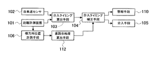
以下に、本発明の衝突回避支援システムを図に基づいて説明する。図1は、本発明に係る衝突回避支援システムの一実施形態の全体構成を示している。 Below, the collision avoidance assistance system of this invention is demonstrated based on figures. FIG. 1 shows the overall configuration of an embodiment of a collision avoidance support system according to the present invention.
距離計測装置101は、車両前部に取り付けられたレーザレーダで構成されており、前方障害物との距離を計測するものであり、また、前回計測した測定距離と今回計測した測定距離とにより自車と前方障害物との相対速度を算出する。距離計測装置101はレーザレーダに限られず、前方障害物との距離を計測できればよいものである。距離計測装置101をミリ波レーダにすると、前方障害物との距離と相対速度を同時に計測できる。
The distance measuring
自車速センサ102は、トランスミッション出力軸の回転速度すなわち車速に比例した数の出力パルスを発生するように取り付けられており、自車の速度を計測する。また、自車速センサ102としては、各車輪毎に回転速度に比例したパルスを発生するように取り付けてもよい。介入タイミング算出手段103は、距離計測装置101で計測された前方障害物との距離と、自車と前方障害物との相対速度とから、そのままの速度で走行を続けた場合に前方障害物と衝突するまでの余裕時間である衝突到達時間TTCを算出するとともに、前方障害物との衝突を回避するために必要な衝突回避時間TTB、すなわち、自車と前方障害物とが所定の距離離れた位置で、自車が制動操作によって前方障害物との相対速度を0とするのに必要な時間を算出する。衝突到達時間TTCが衝突回避時間TTBとなったときは衝突を回避するための制動操作を開始する予定のときであるから、衝突回避時間TTBは介入予定タイミングといえる。
The own
横方向位置計測手段106は、レーザレーダで構成された距離計測装置101を用いており、距離計測装置101を横方向にスキャンさせて、自車の走行する予定進路における障害物の大きさと位置を計測する。横方向位置計測手段106は、距離計測装置101がミリ波レーダで構成されている場合であれば複数アンテナの出力を用いた開口合成により横方向の情報を再構成するようにしてもよい。また、横方向位置計測手段106は、距離計測装置101を用いないで、障害物の横方向の位置を検出するための手段を新たに設けてもよい。
The lateral position measuring means 106 uses a
進路余裕度算出手段112は、自車が走行すると推定される推定進路を演算するとともに、横方向位置計測手段106が計測した自車の走行する予定進路にある障害物の大きさと位置に基づいて該障害物の横方向位置が、自車の推定進路内に占める大きさ(幅)を算出する。
The course margin calculation means 112 calculates an estimated course estimated that the host vehicle will travel, and based on the size and position of the obstacle on the planned path traveled by the host vehicle measured by the lateral
介入タイミング補正手段104は、進路余裕度算出手段112で算出された該推定進路内に占める前方障害物の大きさによって介入タイミング算出手段103により算出された衝突回避時間TTBに対して介入操作を補正する。すなわち、自車の推定進路幅内に占める前方障害物の大きさが小さい場合には、運転者の操舵操作により短時間で前方障害物をさけることができるので、衝突回避時間TTBを短縮するように補正して衝突回避決定時間TTDを決定する。そして、衝突到達時間TTCが衝突回避決定時間TTDになると、制動操作手段による制動介入を開始する信号を介入手段105に出力する。衝突到達時間TTCが衝突回避決定時間TTDとなったときは衝突を回避するための制動操作を開始するので、衝突回避決定時間TTDは介入開始タイミングといえる。
The intervention
介入手段105は、本実施形態ではブレーキを作動させる制動操作によって衝突を回避する制動操作手段を備えるものであり、介入タイミング補正手段104から制動介入を開始する信号が入力されると、制動操作手段による制動介入を開始する。このようにして、前方障害物との衝突の可能性に応じて該障害物との衝突が回避されるように車両の制動力を制御する。 In this embodiment, the intervention means 105 includes a braking operation means for avoiding a collision by a braking operation for operating the brake. When a signal for starting the braking intervention is input from the intervention timing correction means 104, the braking operation means Start braking intervention by. In this way, the braking force of the vehicle is controlled so that the collision with the obstacle is avoided according to the possibility of the collision with the front obstacle.
本実施形態では、衝突回避時間TTBを補正することによって障害物回避の容易さに応じて介入開始タイミングを遅らせ、その間に運転者による障害物の回避操作が行われると制動介入を行う必要がなくなるので、不要な介入を減らして運転者への違和感を低減することが可能となる。警報手段110は、制動介入を開始するときやその直前に介入制御が行われること、あるいは、回避するための操作が必要なこと等を運転者に音等により報知するものである。本実施形態では、前方障害物との衝突を回避するのに制動操作によって介入制御を行っているが、操舵操作による介入制御によって前方障害物との衝突を回避するように構成してもよい。 In this embodiment, by correcting the collision avoidance time TTB, the intervention start timing is delayed according to the ease of obstacle avoidance, and if the driver performs an obstacle avoidance operation during that time, it is not necessary to perform braking intervention. As a result, unnecessary intervention can be reduced to reduce the driver's uncomfortable feeling. The warning means 110 notifies the driver by sound or the like that intervention control is performed immediately before or when braking intervention is started, or that an operation for avoiding the intervention is necessary. In the present embodiment, intervention control is performed by a braking operation to avoid a collision with a front obstacle. However, a collision with a front obstacle may be avoided by intervention control by a steering operation.
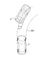
次に、前述の進路余裕度算出手段112において、自車が走行する推定進路の推定の仕方(演算)について図2を用いて説明する。図2において、1は自車、2は前方障害物(先行他車)である。自車1は、内界センサとして自車速センサ102、操舵角センサ、ヨーレートセンサが設けられており、自車速度、操舵角及びヨーレートを検出する。したがって、自車速センサ102、操舵角センサ、ヨーレートセンサからの信号に基づいて、自車1の操舵角及び自車速度の情報から幾何学的に自車がこれから通過すると推定される推定進路201を演算する。この推定進路201と横方向位置計測手段106で計測した障害物2の位置と横方向の大きさを進路余裕度算出手段112によって比較することにより、障害物2の横方向位置が自車の推定進路幅201内に占める大きさ(幅)d1を算出することができる。より望ましくは、例えば自車1の走行運動モデルをオブザーバとして用い、操舵角、自車速度に加えてヨーレートや横加速度などの物理量を検出して入力することにより、より精度良く推定進路201を求めることが可能である。
Next, a method (calculation) of estimating an estimated course on which the host vehicle travels in the course margin calculation means 112 will be described with reference to FIG. In FIG. 2, 1 is the own vehicle, and 2 is a front obstacle (preceding other vehicle). The
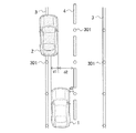
さらに、自車の走行する推定進路の別の推定の仕方について図3を用いて説明する。図3は自車1と障害物2の位置関係を上から見た図であり、自車1が走行する道路は路肩の白線3及びセンターライン4により定められている。この道路に路上の位置を特定するための手段としての磁気ネイル301が埋め込まれており、自車1はこの磁気ネイル301の位置を計測して自車の現在の位置(d3)を把握するとともに内界センサからの信号に基づいて自車の走行する推定進路を、センターライン4(又は路肩の白線3)を基準として推定できる。また、障害物の位置もセンターライン4を基準として把握する。この方法によれば、障害物2の横方向位置が自車の推定進路内に占める大きさd1だけでなく、自車1が通過可能な道路の幅d2も求めることができるため、介入予定タイミングを補正してより的確な介入開始タイミングを決定することが可能となる。
Further, another method of estimating the estimated course traveled by the host vehicle will be described with reference to FIG. FIG. 3 is a view of the positional relationship between the
以上のように、本実施形態では、自車1の走行する予定進路における障害物2の大きさと位置を計測して障害物の横方向位置が自車の推定進路内に占める大きさd1もしくは自車1の通過可能幅d2を確認し、ここでもし障害物の位置が自車の推定進路内を大きく塞いでいないと判定した場合には、介入開始タイミングを当初よりも遅らせるように補正することで回避が容易な場合における不要な介入操作が低減され、運転者への違和感を低減することが可能となる。
As described above, in the present embodiment, the size and position of the
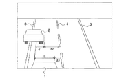
図4は、図1における横方向位置計測手段106が車両前部に取り付けられたCCDカメラからなる撮像装置で構成されている場合において、自車が走行する推定進路の推定の仕方を説明するためのものであり、撮像装置で撮像した映像を示している。車両前部に取り付けられ撮像装置からは自車1から見た車両前方の映像が進路余裕度算出手段112に出力される。この映像には、前方の障害物2の他に、自車1が走行している道路の路肩の白線3及びセンターライン4、さらに自車1自身の車体の一部が含まれるように、自車1への撮像装置の取り付け位置が選択されている。
FIG. 4 is a diagram for explaining a method of estimating an estimated course traveled by the own vehicle when the lateral
進路余裕度算出手段112は、この映像に対してエッジ抽出や特徴点抽出(得られたエッジ情報から直線や自動車、人などのパターンを抽出する処理)などの画像処理を施すことにより、風景映像の中から前述の路肩の白線3、センターライン4、自車1の車体等の計測対象を分離することができる。さらに撮像装置の自車1への取り付け位置は既知であるので、内界センサからの信号に基づいて自車の走行する推定進路を、センターライン4(又は路肩の白線3)を基準として推定できる。また、対象物位置は撮像装置の光学系における対象物と撮像素子上の像の対照関係から求められることは周知の事実であり、また、映像中の自車1の幅Lなどは既知の長さであるので、これを利用するとともに前方障害物2までの距離により横方向距離の補正を行い、センターライン4(又は路肩の白線3)を基準とした前方障害物2の位置と大きさを算出する。このようにして、自車の走行する道路の幅や障害物2の横方向位置を自車1に取り付けた装置だけで計測することが可能となり、前方障害物2の横方向の位置が自車の同一車線上に占める大きさd1及びd2が求められることから介入予定タイミングを補正してより的確な介入開始タイミングを決定することが可能となる。
The course allowance calculating means 112 performs landscape processing on the video by performing image processing such as edge extraction and feature point extraction (processing for extracting patterns such as straight lines, cars, and people from the obtained edge information). It is possible to separate measurement objects such as the
以上のように、本実施形態における横方向位置計測手段106では、自車の走行する車線範囲における障害物の大きさと位置を計測するためにビデオカメラなどの撮像装置を使用することで障害物と同時に自車1の走行する道路上の白線、すなわち路肩の車線及びセンターラインなどの位置を計測し、実際の車線範囲に対して障害物がどの程度塞いでいるかをより高精度に判定することが可能である。これにより、障害物の横方向位置が自車の推定車線内に占める大きさd1及び自車1の通過可能幅d2を確認し、ここでもし障害物の位置が自車の推定進路内を大きく塞いでいないと判定した場合には、介入操作タイミングを当初の介入操作よりも遅らせるように補正することで回避が容易な場合における不要な介入操作が低減され、運転者への違和感を低減することが可能となる。
As described above, the lateral
次に、図5のフローチャートにより、本発明の衝突回避支援システムにおける制御処理について説明する。まず、ステップ701で、自車速度を読み込むとともに障害物との距離を読み込み、テップ702において、障害物との相対速度を算出し、障害物との距離と相対速度から、そのままの速度で走行を続けたときに前方障害物と衝突するまでの時間である衝突到達時間TTCを算出する。また、ステップ703で、相対速度に基づいて前方障害物との衝突を回避するのに必要な、介入予定タイミングとなる衝突回避時間TTBを算出する。その後ステップ704で、障害物の横方向位置の読み込みを行なう。ステップ705においては、自車の推定進路を演算し、障害物が推定進路内に占める大きさを算出するとともに、障害物が推定進路内に占める大きさに基づいて介入タイミング補正量Dを算出する。ステップ706では、ステップ703で算出した衝突回避時間TTBを介入タイミング補正量Dにより補正して介入開始タイミング(TTB×D)を算出し、これを衝突到達時間TTCと比較することで介入制御を開始するか否かを判定する。もし、衝突到達時間TTCが介入開始タイミング(TTB×D)以下であれば、ステップ707により制動操作または操舵操作による目標介入量の算出及び介入制御を行う。一方、衝突到達時間TTCが介入開始タイミング(TTB×D)に達していなければ、介入制御を行なわずに処理を終える。このような処理手順を制御周期ごとに繰り返すことで車両の衝突回避の支援を行なう。
Next, control processing in the collision avoidance support system of the present invention will be described with reference to the flowchart of FIG. First, in
図6、7により、本発明の衝突回避支援システムの他の実施形態を説明する。この実施形態では、図1における介入手段105が、制動操作によって衝突を回避する制動介入手段と操舵操作によって衝突を回避する操舵介入手段等の複数の介入手段を備えている。 Another embodiment of the collision avoidance support system of the present invention will be described with reference to FIGS. In this embodiment, the intervention means 105 in FIG. 1 includes a plurality of intervention means such as a braking intervention means for avoiding a collision by a braking operation and a steering intervention means for avoiding a collision by a steering operation.
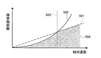
図6に示すように、制動介入手段による衝突回避可能距離と操舵介入手段による衝突回避可能距離とは障害物との相対速度の違いによって異なる。図6において、線501は操舵操作によって衝突回避するのに必要な操舵回避限界距離を示し、線502は制動操作によって衝突回避するのに必要な制動回避限界距離を示している。すなわち、縦軸の障害物までの距離がこれらの回避限界距離を下回る場合は衝突回避が不可能であることを示している。線502の制動回避限界距離は、車両の減速度が最大、すなわち路面摩擦係数で決まる一定の減速度である場合の限界距離で、相対速度の2乗に比例して増加する。一方、線501の操舵回避限界距離は、操舵により一定速度の横移動が生じると仮定した場合の限界距離であり、相対速度に対して線形に増加する。すなわち、相対速度が値503より遅いときには、操舵操作によって衝突を回避するよりも制動操作によって衝突を回避する方が有利であり、また、相対速度が値503より速いときには、制動操作によるよりも操舵操作による方が有利になる。よって、制動介入手段による介入制御を行うか、操舵介入手段による介入制御を行うか、その介入手段を適切に選択することによって、図6の範囲504のように回避限界距離をより小さくすることが可能である。
As shown in FIG. 6, the collision avoidable distance by the braking intervention means and the collision avoidable distance by the steering intervention means differ depending on the difference in relative speed with the obstacle. In FIG. 6, a
そこで、図1の介入タイミング補正手段104中に、図7に示すような介入手段選択テーブルを備えておき、どの介入手段を優先して動作させたらよいかを適切に選択する。図7には、障害物に対する相対速度と障害物が自車の推定進路内を塞ぐ大きさの2つのパラメータを用い、相対速度の大小と障害物が自車の推定進路内を塞ぐ大きさの大小により4つの範囲に分け、その範囲で動作させるべき介入手段を示している。障害物が自車の推定進路内を塞ぐ幅が小さく操舵操作することにより回避が容易な場合には、相対速度が大きいときは警報手段110により運転者に回避操作を促すが、相対速度が小さいときは介入制御を行っていない。しかし、どの介入手段を優先して動作させるかの介入手段選択テーブルはこれに限定されるものではない。 Therefore, an intervention means selection table as shown in FIG. 7 is provided in the intervention timing correction means 104 of FIG. 1 to appropriately select which intervention means should be preferentially operated. FIG. 7 uses two parameters, relative speed to the obstacle and the size of the obstacle blocking the estimated course of the vehicle. The magnitude of the relative speed and the magnitude of the obstacle blocking the estimated path of the vehicle. The intervention means to be operated in the four ranges are shown according to the size. When obstacles block the estimated course of the vehicle and the steering is small and easy to avoid, when the relative speed is large, the warning means 110 prompts the driver to perform the avoidance operation, but the relative speed is small. Sometimes no intervention control is performed. However, the intervention means selection table indicating which intervention means is to be preferentially operated is not limited to this.
また、介入タイミング補正手段104は制動介入手段と操舵介入手段との2つの介入制御を同時に行なうようにしてもよく、例えば、相対速度が大きくかつ障害物が自車の推定進路内を塞ぐ幅が大きい場合には制動介入手段によって制動するとともに操舵介入手段によって操舵して衝突を回避する。この場合には、介入手段選択テーブルの範囲によってそれぞれの介入手段による介入操作の割合が異なるようにテーブルを構成してもよい。 Further, the intervention timing correction means 104 may perform two intervention controls of the braking intervention means and the steering intervention means at the same time. If it is larger, the vehicle is braked by the braking intervention means and steered by the steering intervention means to avoid a collision. In this case, the table may be configured so that the ratio of intervention operations by each intervention means varies depending on the range of the intervention means selection table.
以上のように本実施形態の介入タイミング補正手段104では、障害物との相対速度と障害物が自車の自車の推定進路内を塞ぐ幅の大きさに基づいて衝突を回避するための介入手段を選択し、介入操作を効果的に行うことが可能となる。
As described above, in the intervention
図8は、本発明の衝突回避支援システムの他の実施形態を示しており、図1に示す実施形態のものと同じ構成には同じ符号を付している。本実施形態では、図1に示す衝突回避支援システムと比べ、後側方距離測定装置、路面状況推定手段、運転者判別手段及び外部通信手段が追加されている。 FIG. 8 shows another embodiment of the collision avoidance support system of the present invention, and the same reference numerals are given to the same components as those of the embodiment shown in FIG. In this embodiment, compared with the collision avoidance support system shown in FIG. 1, a rear side distance measuring device, road surface condition estimating means, driver discrimination means, and external communication means are added.
後側方距離計測装置107は、車両後部に取り付けられたレーザレーダで構成されており、後方障害物との距離を計測するものであり、また、前回計測した測定距離と今回計測した測定距離により自車と前方障害物との相対速度をも測定する。ここで後側方距離計測装置107はレーザレーダに限られず、ミリ波レーダでもよく、ミリ波レーダであれば、後方障害物との距離と相対速度を同時に計測できる。そして、後側方距離計測装置107で計測した後方障害物についての情報は介入タイミング補正手段104に入力され、介入タイミング補正手段104は、隣接車線で後方から追い上げてくる車両等の有無を考慮し、操舵操作による衝突回避を安全に行えるかを判定した上で介入手段の選択を行うので、衝突回避支援システムの安全性を一層増すことができる。
The rear side
路面状況推定手段108は、路面の滑り易さ等の路面状況を把握するものであり、駆動輪である前輪の速度と後輪速度との差に基づいて路面摩擦係数を把握し、この路面状況推定手段108で把握された路面摩擦係数の情報を介入タイミング補正手段104に入力している。また、路面摩擦係数の把握は制動時の車輪変化速度から把握してもよい。そして、路面摩擦係数により図6で示した制動回避限界距離と操舵回避限界距離とが変わることになるので、介入タイミング補正手段104は、路面摩擦係数をも考慮した介入タイミング補正量Dによって衝突回避時間TTBを補正して介入開始タイミング(TTB×D)を算出する。本実施形態では、雨や冬季の凍結、積雪などの路面状況、特に路面の滑り易さを考慮して介入開始タイミングを決定しているので、衝突回避支援システムの安全性を一層増すことができる。
The road surface condition estimating means 108 grasps the road surface condition such as the slipperiness of the road surface, grasps the road surface friction coefficient based on the difference between the speed of the front wheel which is the driving wheel and the rear wheel speed, and this road surface condition. Information on the road surface friction coefficient grasped by the estimating means 108 is inputted to the intervention
運転者判別手段109は、運転者ごとのキーを用意しこのキーを挿入することにより運転者を判別する。車間距離を大きく保ってする運転する運転者によっては介入タイミングが遅延すると却って恐怖感やシステムへの不信感を増大してしまう可能性があるし、逆に普段から車間距離の小さい状態で運転をしている運転者にとっては、介入予定タイミングの遅延補正をしてもなお御節介な介入をするシステムだと感じる可能性がある。そこで、運転者判別手段109で運転者を判別し、判別した運転者の情報を介入タイミング補正手段104に入力し、介入タイミング補正手段104が運転者個別の好みに適応するように運転者に応じた介入タイミング補正をするように制御する。ここで、運転者判別手段109としては、運転者が選択ボタンを押下させる簡便なものでもよいし、運転者を撮影するカメラ、例えば居眠り検知システムのカメラを流用して顔認識データから運転者を特定するもの、ハンドルなどに取り付けた静脈認証システムによって運転者を特定するもの、カーナビやハンズフリーフォンの音声入力による音声認識によって運転者を特定するものなどのいずれであってもよい。 The driver discriminating means 109 prepares a key for each driver and inserts this key to discriminate the driver. Depending on the driver who keeps the inter-vehicle distance large, if the intervention timing is delayed, there is a possibility that fear and distrust to the system may increase, and conversely, driving with a small inter-vehicle distance from the usual For the driver who is doing this, there is a possibility that even if the delay of the scheduled intervention timing is corrected, the system still intervenes in the middle. Therefore, the driver discriminating means 109 discriminates the driver, inputs the discriminated driver information to the intervention timing correction means 104, and responds to the driver so that the intervention timing correction means 104 adapts to the individual preference of the driver. Control to correct the intervention timing. Here, the driver discriminating means 109 may be a simple one in which the driver presses the selection button, or a camera for photographing the driver, for example, a camera of a dozing detection system is used to identify the driver from the face recognition data. Any one of specifying, a driver specifying by a vein authentication system attached to a handle, etc., or specifying a driver by voice recognition by voice input of a car navigation system or a hands-free phone may be used.
以上のように、本実施形態では運転者判別手段109を備え、運転者の運転傾向を考慮して介入予定タイミングの補正を行うことにより、介入制御による運転者への違和感を低減できる。 As described above, in the present embodiment, the driver discriminating means 109 is provided, and by correcting the scheduled intervention timing in consideration of the driving tendency of the driver, it is possible to reduce the uncomfortable feeling to the driver due to the intervention control.
外部通信手段111は、道路側に設けられ基地局と無線等の通信手段によって交信し、他車両等の障害物の情報を入手して介入タイミング算出手段103に入力する。外部通信手段111は、例えば、塀等によって距離計測装置101で検知することのできなかった車両の情報を入手可能である。介入タイミング算出手段103は、距離計測装置101に加え基地局からの情報により自車の予定進路にある障害物を把握することができるので、介入タイミング算出手段103は、障害物を確実に把握して介入予定タイミングを算出することができる。また、外部通信手段111は、本実施形態と同様の衝突回避支援システムを搭載した近隣の他車両と交信してもよいし、道路上に備え付けたセンサやビーコン、カメラなどの情報収集手段によって得られる車両位置情報を収集してもよい。前者の近隣の他車両である場合には、例えば各車両が備えたGPSシステムによる車両位置情報を付加して無線通信手段によって相互に情報を授受したり、同様の衝突回避支援システムを搭載した車両同士で位置情報や加減速、旋回などの行動情報を共有することで、該介入開始タイミングを決定するための障害物の位置情報をより詳細で高精度なものにすることが可能になる。
The external communication means 111 is provided on the road side and communicates with the base station by wireless communication means, obtains information on obstacles such as other vehicles, and inputs the information to the intervention timing calculation means 103. The external communication unit 111 can obtain information on a vehicle that could not be detected by the
本実施形態の衝突回避支援システムは、後側方距離測定装置107、路面状況推定手段108、運転者判別手段109及び外部通信手段111を備えているが、これらは全て備える必要はなく、適宜必要に応じて前記手段を選択して備えればよく、例えば、後側方距離測定装置107のみを備えてもよい。
The collision avoidance support system according to the present embodiment includes the rear side
以上、本発明の実施形態について説明したが、本発明は前記実施形態に限定されるものでなく、特許請求の範囲に記載された発明の精神を逸脱しない範囲で、設計において種々の変更ができるものである。 Although the embodiments of the present invention have been described above, the present invention is not limited to the above-described embodiments, and various modifications can be made in the design without departing from the spirit of the invention described in the claims. Is.
1…自車
2…障害物
3…白線
4…センターライン
101…距離計測装置
102…自車速センサ
103…介入タイミング算出手段
104…介入タイミング補正手段
105…介入手段
106…横方向位置計測手段
107…後側方距離測定装置
108…路面状況推定手段
109…運転者判別手段
110…警報手段
111…外部通信手段111
112…進路余裕度算出手段
201…推定進路
301…磁気ネイル
DESCRIPTION OF
112 ... Course margin calculating means 201 ... Estimated
Claims (8)
前方障害物との距離情報と前方障害物と自車との相対速度情報とから前記介入制御を開始する介入予定タイミングを算出する介入タイミング算出手段と、
自車の走行する予定進路にある前方障害物の横方向の大きさと位置情報から前方障害物が自車の推定進路内を塞ぐ大きさを算出する進路余裕度算出手段と、
前記進路余裕度算出手段で算出した推定進路内を塞ぐ大きさによって前記介入予定タイミングを補正して介入開始タイミングを決定する介入タイミング補正手段と、を備えると共に、
前記進路余裕度算出手段は、道路上の白線を基準とした前方障害物の位置と大きさを算出するとともに、前記白線を基準とした自車の推定進路を推定し、前方障害物の位置及び大きさと自車の前記推定進路とに基づいて前方障害物が自車の推定進路内を塞ぐ大きさを算出し、
前記介入タイミング補正手段は、前記前方障害物が自車の推定進路内を塞ぐ大きさと障害物と自車との相対速度に基づいて制動操作による介入制御か操舵操作による介入制御かを選択することを特徴とする衝突回避支援システム。 A collision avoidance support system that performs intervention control so as to avoid a collision with a front obstacle by a braking operation or a steering operation or a braking operation and a steering operation of a vehicle according to a possibility of a collision with a front obstacle,
Intervention timing calculation means for calculating an intervention scheduled timing for starting the intervention control from distance information with a front obstacle and relative speed information between the front obstacle and the own vehicle;
Course margin calculation means for calculating the size of the front obstacle blocking the estimated course of the own vehicle from the lateral size and position information of the forward obstacle on the planned course on which the host vehicle is traveling,
Intervention timing correction means for determining the intervention start timing by correcting the intervention scheduled timing according to the size of the estimated course calculated by the course margin calculation means ,
The course margin calculation means calculates the position and size of a front obstacle with reference to a white line on the road, estimates the estimated course of the vehicle with reference to the white line, and determines the position of the front obstacle and Based on the size and the estimated course of the vehicle, calculate the size that the front obstacle blocks the estimated course of the vehicle,
The intervention timing correction means selects between intervention control by a braking operation or intervention control by a steering operation based on a size at which the front obstacle covers the estimated course of the own vehicle and a relative speed between the obstacle and the own vehicle. A collision avoidance support system characterized by
前記進路余裕度算出手段は、車両の前方に取り付けられた横方向位置計測手段で計測した、前方障害物の横方向の大きさと位置に基づいて前方障害物が自車の推定進路内を塞ぐ大きさを算出することを特徴とする請求項1記載の衝突回避支援システム。 The intervention timing calculation means is a scheduled intervention timing for starting the intervention control based on a distance from a front obstacle and a relative speed between the host vehicle and the front obstacle measured by a distance measuring device attached in front of the vehicle. To calculate
The course margin calculation means is a size in which the front obstacle blocks the estimated course of the own vehicle based on the lateral size and position of the front obstacle measured by the lateral position measurement means attached to the front of the vehicle. The collision avoidance support system according to claim 1, wherein the collision avoidance support system is calculated.
Priority Applications (1)
| Application Number | Priority Date | Filing Date | Title |
|---|---|---|---|
| JP2006320439A JP4909030B2 (en) | 2006-11-28 | 2006-11-28 | Collision avoidance support system and vehicle equipped with the same |
Applications Claiming Priority (1)
| Application Number | Priority Date | Filing Date | Title |
|---|---|---|---|
| JP2006320439A JP4909030B2 (en) | 2006-11-28 | 2006-11-28 | Collision avoidance support system and vehicle equipped with the same |
Publications (2)
| Publication Number | Publication Date |
|---|---|
| JP2008132867A JP2008132867A (en) | 2008-06-12 |
| JP4909030B2 true JP4909030B2 (en) | 2012-04-04 |
Family
ID=39558031
Family Applications (1)
| Application Number | Title | Priority Date | Filing Date |
|---|---|---|---|
| JP2006320439A Expired - Fee Related JP4909030B2 (en) | 2006-11-28 | 2006-11-28 | Collision avoidance support system and vehicle equipped with the same |
Country Status (1)
| Country | Link |
|---|---|
| JP (1) | JP4909030B2 (en) |
Cited By (1)
| Publication number | Priority date | Publication date | Assignee | Title |
|---|---|---|---|---|
| EP4201762A1 (en) | 2021-12-24 | 2023-06-28 | Suzuki Motor Corporation | Vehicle control system |
Families Citing this family (29)
| Publication number | Priority date | Publication date | Assignee | Title |
|---|---|---|---|---|
| JP5244787B2 (en) | 2007-03-29 | 2013-07-24 | トヨタ自動車株式会社 | Collision possibility acquisition device and collision possibility acquisition method |
| JP4450023B2 (en) | 2007-07-12 | 2010-04-14 | トヨタ自動車株式会社 | Own vehicle risk acquisition device |
| JP5416372B2 (en) * | 2008-07-17 | 2014-02-12 | 富士重工業株式会社 | Lane departure prevention device |
| JP5254688B2 (en) * | 2008-07-17 | 2013-08-07 | 富士重工業株式会社 | Lane departure prevention device |
| JP2010030396A (en) | 2008-07-28 | 2010-02-12 | Denso Corp | Safety controller for vehicle |
| JP2010179761A (en) * | 2009-02-05 | 2010-08-19 | Nissan Motor Co Ltd | Device and method for supporting driving operation |
| JP2010179843A (en) * | 2009-02-06 | 2010-08-19 | Nissan Motor Co Ltd | Device and method for supporting driving operation |
| JP4748232B2 (en) | 2009-02-27 | 2011-08-17 | トヨタ自動車株式会社 | Driving assistance device |
| JP5560811B2 (en) * | 2010-03-23 | 2014-07-30 | トヨタ自動車株式会社 | Steering support device |
| JP5507433B2 (en) * | 2010-12-21 | 2014-05-28 | ダイハツ工業株式会社 | Driving assistance device |
| WO2014037997A1 (en) * | 2012-09-04 | 2014-03-13 | トヨタ自動車株式会社 | Collision avoidance assistance device and collision avoidance assistance method |
| DE112012007158B4 (en) * | 2012-11-21 | 2020-11-05 | Toyota Jidosha Kabushiki Kaisha | Driving assistance device and driving assistance method |
| WO2014080484A1 (en) * | 2012-11-21 | 2014-05-30 | トヨタ自動車株式会社 | Driving-assistance device and driving-assistance method |
| EP3079961B1 (en) * | 2013-12-11 | 2021-08-18 | Intel Corporation | Individual driving preference adapted computerized assist or autonomous driving of vehicles |
| JP6209969B2 (en) * | 2014-01-07 | 2017-10-11 | トヨタ自動車株式会社 | Driving assistance device |
| JP6257349B2 (en) * | 2014-01-23 | 2018-01-10 | ダイハツ工業株式会社 | Driving assistance device |
| WO2016024315A1 (en) * | 2014-08-11 | 2016-02-18 | 日産自動車株式会社 | Travel control device and method for vehicle |
| JP6539228B2 (en) * | 2015-06-16 | 2019-07-03 | 株式会社デンソー | Vehicle control device and vehicle control method |
| WO2016204213A1 (en) * | 2015-06-16 | 2016-12-22 | 株式会社デンソー | Vehicle control device and vehicle control method |
| JP6347242B2 (en) * | 2015-09-15 | 2018-06-27 | マツダ株式会社 | Vehicle control device |
| CN108712981A (en) * | 2016-03-07 | 2018-10-26 | 本田技研工业株式会社 | Vehicle control device, vehicle control method, and vehicle control program |
| JP6859902B2 (en) | 2017-08-31 | 2021-04-14 | トヨタ自動車株式会社 | Vehicle control unit |
| CN108407807B (en) * | 2018-03-15 | 2023-11-17 | 东风商用车有限公司 | Steering collision avoidance system of commercial vehicle and control method thereof |
| KR102715606B1 (en) * | 2019-06-11 | 2024-10-11 | 주식회사 에이치엘클레무브 | Advanced Driver Assistance System, Vehicle having the same and method for controlling the vehicle |
| JP7424760B2 (en) * | 2019-06-12 | 2024-01-30 | 株式会社Subaru | Vehicle control device |
| JP7325920B2 (en) * | 2021-01-25 | 2023-08-15 | ダイハツ工業株式会社 | vehicle controller |
| JP7387241B2 (en) * | 2021-06-18 | 2023-11-28 | ダイハツ工業株式会社 | Vehicle control device |
| JP7517294B2 (en) * | 2021-09-27 | 2024-07-17 | トヨタ自動車株式会社 | Target vehicle recognition device and processing method for target vehicle recognition device |
| CN117125056B (en) * | 2023-09-27 | 2025-01-28 | 岚图汽车科技有限公司 | A control method, device, equipment and storage medium for avoiding vehicles |
Family Cites Families (5)
| Publication number | Priority date | Publication date | Assignee | Title |
|---|---|---|---|---|
| JP3469960B2 (en) * | 1995-04-20 | 2003-11-25 | 光洋精工株式会社 | Vehicle steering system |
| JP3433650B2 (en) * | 1997-06-25 | 2003-08-04 | 三菱自動車工業株式会社 | Driving lane recognition device |
| JP4011711B2 (en) * | 1998-01-13 | 2007-11-21 | 本田技研工業株式会社 | Vehicle travel safety device |
| JP2005028992A (en) * | 2003-07-11 | 2005-02-03 | Toyota Motor Corp | Vehicle control system for collision |
| JP4454490B2 (en) * | 2004-12-17 | 2010-04-21 | ダイハツ工業株式会社 | Collision prevention support method and collision prevention support apparatus |
-
2006
- 2006-11-28 JP JP2006320439A patent/JP4909030B2/en not_active Expired - Fee Related
Cited By (1)
| Publication number | Priority date | Publication date | Assignee | Title |
|---|---|---|---|---|
| EP4201762A1 (en) | 2021-12-24 | 2023-06-28 | Suzuki Motor Corporation | Vehicle control system |
Also Published As
| Publication number | Publication date |
|---|---|
| JP2008132867A (en) | 2008-06-12 |
Similar Documents
| Publication | Publication Date | Title |
|---|---|---|
| JP4909030B2 (en) | Collision avoidance support system and vehicle equipped with the same | |
| CN110103967B (en) | Automatic lane changing method for vehicle, vehicle control system and vehicle | |
| CN107783535B (en) | Vehicle control device | |
| JP6344275B2 (en) | Vehicle control device | |
| US10513267B2 (en) | Vehicle safety system | |
| JP5979259B2 (en) | Collision avoidance control device | |
| CN102044170B (en) | Vehicle driving support control apparatus | |
| US8630793B2 (en) | Vehicle controller | |
| CN107004367B (en) | Vehicle travel control device and travel control method | |
| US9150221B2 (en) | Vehicle controller, control method for vehicle and control system for vehicle | |
| JP7143722B2 (en) | Vehicle position estimation device | |
| JP2009003795A (en) | Branch entry judgment device | |
| CN109388137B (en) | Driving assistance apparatus and storage medium | |
| CN105936276A (en) | Travel control device | |
| CN106114217A (en) | Travel controlling system | |
| WO2011125168A1 (en) | Vehicle collision judgment device | |
| JP2018002083A (en) | Vehicle control device | |
| JP2020021179A (en) | Driving support device | |
| JP2010125923A (en) | Emergency refuge device | |
| TW201704067A (en) | Collision avoidance method, computer program product for said collision avoidance method and collision avoidance system | |
| JP7579132B2 (en) | Driving Support Devices | |
| JP2005258941A (en) | Obstacle detection device | |
| JP5298104B2 (en) | Vehicle control device | |
| WO2020020525A1 (en) | Method for performing an overtaking maneuver including considering a safety distance, analyzing component, driver assistance system, as well as vehicle | |
| KR101745015B1 (en) | Apparatus and method for controlling obstacle sensing zone |
Legal Events
| Date | Code | Title | Description |
|---|---|---|---|
| A621 | Written request for application examination |
Free format text: JAPANESE INTERMEDIATE CODE: A621 Effective date: 20081017 |
|
| A711 | Notification of change in applicant |
Free format text: JAPANESE INTERMEDIATE CODE: A712 Effective date: 20100115 |
|
| A521 | Request for written amendment filed |
Free format text: JAPANESE INTERMEDIATE CODE: A523 Effective date: 20110830 |
|
| TRDD | Decision of grant or rejection written | ||
| A01 | Written decision to grant a patent or to grant a registration (utility model) |
Free format text: JAPANESE INTERMEDIATE CODE: A01 Effective date: 20120110 |
|
| A01 | Written decision to grant a patent or to grant a registration (utility model) |
Free format text: JAPANESE INTERMEDIATE CODE: A01 |
|
| A61 | First payment of annual fees (during grant procedure) |
Free format text: JAPANESE INTERMEDIATE CODE: A61 Effective date: 20120113 |
|
| FPAY | Renewal fee payment (event date is renewal date of database) |
Free format text: PAYMENT UNTIL: 20150120 Year of fee payment: 3 |
|
| R150 | Certificate of patent or registration of utility model |
Ref document number: 4909030 Country of ref document: JP Free format text: JAPANESE INTERMEDIATE CODE: R150 Free format text: JAPANESE INTERMEDIATE CODE: R150 |
|
| S533 | Written request for registration of change of name |
Free format text: JAPANESE INTERMEDIATE CODE: R313533 |
|
| R350 | Written notification of registration of transfer |
Free format text: JAPANESE INTERMEDIATE CODE: R350 |
|
| LAPS | Cancellation because of no payment of annual fees |