JP4901923B2 - Refinement mixing equipment - Google Patents
Refinement mixing equipment Download PDFInfo
- Publication number
- JP4901923B2 JP4901923B2 JP2009190475A JP2009190475A JP4901923B2 JP 4901923 B2 JP4901923 B2 JP 4901923B2 JP 2009190475 A JP2009190475 A JP 2009190475A JP 2009190475 A JP2009190475 A JP 2009190475A JP 4901923 B2 JP4901923 B2 JP 4901923B2
- Authority
- JP
- Japan
- Prior art keywords
- mixed fluid
- flow path
- casing
- miniaturization
- block
- Prior art date
- Legal status (The legal status is an assumption and is not a legal conclusion. Google has not performed a legal analysis and makes no representation as to the accuracy of the status listed.)
- Active
Links
- 239000012530 fluid Substances 0.000 claims description 195
- 239000007789 gas Substances 0.000 claims description 83
- 239000007788 liquid Substances 0.000 claims description 56
- 239000007787 solid Substances 0.000 claims description 25
- 230000002093 peripheral effect Effects 0.000 claims description 15
- 238000005192 partition Methods 0.000 claims description 12
- 238000011144 upstream manufacturing Methods 0.000 claims description 8
- 239000002101 nanobubble Substances 0.000 description 42
- XLYOFNOQVPJJNP-UHFFFAOYSA-N water Substances O XLYOFNOQVPJJNP-UHFFFAOYSA-N 0.000 description 41
- 230000009471 action Effects 0.000 description 22
- 238000004140 cleaning Methods 0.000 description 10
- 230000008439 repair process Effects 0.000 description 9
- 230000003139 buffering effect Effects 0.000 description 8
- 238000000034 method Methods 0.000 description 8
- 125000006850 spacer group Chemical group 0.000 description 7
- 230000008569 process Effects 0.000 description 6
- 230000008859 change Effects 0.000 description 5
- 239000002245 particle Substances 0.000 description 5
- 238000000746 purification Methods 0.000 description 4
- 238000007670 refining Methods 0.000 description 4
- 238000004891 communication Methods 0.000 description 3
- 239000000446 fuel Substances 0.000 description 3
- 239000000203 mixture Substances 0.000 description 3
- 238000010008 shearing Methods 0.000 description 3
- 239000010802 sludge Substances 0.000 description 3
- 238000009360 aquaculture Methods 0.000 description 2
- 244000144974 aquaculture Species 0.000 description 2
- 239000000470 constituent Substances 0.000 description 2
- 230000007423 decrease Effects 0.000 description 2
- 230000000694 effects Effects 0.000 description 2
- 230000005484 gravity Effects 0.000 description 2
- 239000010865 sewage Substances 0.000 description 2
- 239000003981 vehicle Substances 0.000 description 2
- 239000002569 water oil cream Substances 0.000 description 2
- CBENFWSGALASAD-UHFFFAOYSA-N Ozone Chemical compound [O-][O+]=O CBENFWSGALASAD-UHFFFAOYSA-N 0.000 description 1
- 230000002776 aggregation Effects 0.000 description 1
- 238000004220 aggregation Methods 0.000 description 1
- QVGXLLKOCUKJST-UHFFFAOYSA-N atomic oxygen Chemical compound [O] QVGXLLKOCUKJST-UHFFFAOYSA-N 0.000 description 1
- 230000004323 axial length Effects 0.000 description 1
- 239000000839 emulsion Substances 0.000 description 1
- 239000010794 food waste Substances 0.000 description 1
- 239000003501 hydroponics Substances 0.000 description 1
- 239000010842 industrial wastewater Substances 0.000 description 1
- 238000009434 installation Methods 0.000 description 1
- 238000004519 manufacturing process Methods 0.000 description 1
- 230000007246 mechanism Effects 0.000 description 1
- 239000001301 oxygen Substances 0.000 description 1
- 229910052760 oxygen Inorganic materials 0.000 description 1
- 230000000704 physical effect Effects 0.000 description 1
- 238000009372 pisciculture Methods 0.000 description 1
- 238000010099 solid forming Methods 0.000 description 1
- 239000002351 wastewater Substances 0.000 description 1
- 238000004065 wastewater treatment Methods 0.000 description 1
Images


Description
本発明は、液体に混合された気体、液体に混合された他の液体、及び、液体に混合された固体を微細化して液体に混合する微細化混合装置に関する。 The present invention relates to a gas that is mixed with a liquid, another liquid that is mixed with a liquid, and a miniaturization mixing apparatus that makes a solid mixed with a liquid fine and mixes it with the liquid.
従来より、気体や液体を微細化して他の液体に分散させてなる混合流体は、微細化された粒子がバルク状態の場合と異なる物性を示すことから、多くの技術分野で活用されている。 2. Description of the Related Art Conventionally, a mixed fluid obtained by refining a gas or a liquid and dispersing it in another liquid has been utilized in many technical fields because the finely divided particles exhibit physical properties different from those in a bulk state.
例えば、直径が約10nm〜数100nmの気泡(以下、ナノバブルという)を分散させた水を、汚水の浄化や、養殖における成長促進や、植物の栽培促進に利用することが研究されている。ナノバブルの生成方法としては、水に空気を混合してなる混合流体にせん断力を作用させ、空気を微細化してナノバブルを生成する気液せん断法が知られている。気液せん断法を行うナノバブル生成装置としては、筒状のケーシング内に、螺旋状に形成された流路を有する上流側のスクリュー部と、流路壁に突起が配置された下流側のカッター部とを備えたものがある(例えば特許文献1参照)。 For example, it has been studied to use water in which bubbles having a diameter of about 10 nm to several 100 nm (hereinafter referred to as nanobubbles) are dispersed for purification of sewage, promotion of growth in aquaculture, and promotion of plant cultivation. As a method for producing nanobubbles, a gas-liquid shearing method is known in which shearing force is applied to a mixed fluid formed by mixing air with water to generate nanobubbles by refining the air. The nano-bubble generating device that performs the gas-liquid shearing method includes an upstream screw portion having a spirally formed flow channel in a cylindrical casing, and a downstream cutter portion in which protrusions are disposed on the flow channel wall. (For example, refer to Patent Document 1).
このナノバブル生成装置は、ケーシング内に圧送した空気と水の混合流体に、スクリュー部で旋回力と遠心力とを付与した後、カッター部で混合流体中の気泡の分断、微細化を行ない、直径が0.5〜3μm程度の微細気泡を含有する気液混合流体を生成するようになっている。 This nanobubble generating device applies a swirl force and a centrifugal force to the mixed fluid of air and water pumped into the casing, and then divides and refines the bubbles in the mixed fluid at the cutter portion. Produces a gas-liquid mixed fluid containing fine bubbles of about 0.5 to 3 μm.
しかしながら、特許文献1に記載のナノバブル生成装置は、スクリュー部による旋回力及び遠心力の付与と、カッター部による気泡の分断では、ナノバブルの生成効率が低いという問題がある。 However, the nanobubble generating device described in Patent Document 1 has a problem that the generation efficiency of nanobubbles is low when the turning force and centrifugal force are applied by the screw portion and the bubbles are divided by the cutter portion.
また、上記ナノバブル生成装置は、スクリュー部に、ケーシングの内側面に螺旋状の仕切壁が接して配置され、カッター部に、ケーシングの内側面に複数の突起が固定されている。このように、ケーシングに種々の部品が固定されているので、構造が複雑であり、洗浄や補修に手間がかかるという問題がある。 In the nanobubble generating device, a spiral partition wall is disposed in contact with the inner surface of the casing on the screw portion, and a plurality of protrusions are fixed on the inner surface of the casing on the cutter portion. As described above, since various parts are fixed to the casing, the structure is complicated, and there is a problem that it takes time and effort for cleaning and repair.
そこで、本発明の課題は、液体に混合された気体、液体又は固体を効率よく微細化でき、また、洗浄や補修を容易に行うことができる微細化混合装置を提供することにある。 Accordingly, an object of the present invention is to provide a miniaturization mixing apparatus that can efficiently miniaturize a gas, liquid, or solid mixed with a liquid, and that can be easily cleaned and repaired.
上記課題を解決するため、本発明の微細化混合装置は、液体に気体、液体又は固体が混合された混合流体が供給され、この混合流体に含まれる少なくとも1つの気体、液体又は固体を微細化して微細化混合流体を生成する微細化混合装置であって、
混合流体の入口と出口を有するケーシングと、このケーシング内に着脱可能に取り付けられた微細化ユニットとを備え、
上記微細化ユニットは、
上記ケーシングの入口から流入した混合流体を出口に向かって流す流路と、
上記流路の途中に設置され、上記流路の断面積よりも小さい断面積を有する流通孔と、この流通孔に隣接して形成され、混合流体の流れによって振動する振動部とを有する有孔振動体と、
上記流路に連通し、混合流体から分離した気体が溜まる気体溜りと
を有することを特徴としている。
In order to solve the above problems, a miniaturized mixing apparatus of the present invention is supplied with a mixed fluid in which a gas, a liquid or a solid is mixed with a liquid, and refines at least one gas, liquid or solid contained in the mixed fluid. A refined mixing apparatus for producing a refined mixed fluid,
A casing having an inlet and an outlet for the mixed fluid, and a miniaturization unit detachably mounted in the casing,
The miniaturization unit is
A flow path for flowing the mixed fluid flowing in from the inlet of the casing toward the outlet;
A perforated hole installed in the middle of the flow path and having a cross-sectional area smaller than the cross-sectional area of the flow path, and a vibrating part that is formed adjacent to the flow hole and vibrates by the flow of the mixed fluid A vibrating body,
It has the gas reservoir which connects to the said flow path and the gas isolate | separated from the mixed fluid accumulates.
上記構成によれば、ケーシングの入口から流入した混合流体が、微細化ユニットの流路に流入する。流路に流入した混合流体は、有孔振動体の流通孔を通過する際、振動部の作用と気体溜りの作用により、混合流体を形成する気体、液体又は固体が微細化される。微細化された気体、液体又は固体は、媒体の液体と混合されて微細化混合流体が生成され、この微細化混合流体は、ケーシングの出口から排出される。この微細化混合装置によれば、有孔振動体と気体溜りを有する微細化ユニットを備えるので、効率良く微細化混合流体を生成することができる。また、気体、液体又は固体の微細化を行う部分であって、多くの場合に洗浄や補修の対象となる微細化ユニットが、ケーシング内に着脱可能に取り付けられている。したがって、微細化ユニットをケーシングから取り外すことにより、洗浄や補修を容易に行うことができる。 According to the said structure, the mixed fluid which flowed in from the inlet_port | entrance of a casing flows in into the flow path of a refinement | miniaturization unit. When the mixed fluid flowing into the flow path passes through the flow hole of the perforated vibrating body, the gas, liquid, or solid forming the mixed fluid is refined by the action of the vibrating portion and the action of the gas reservoir. The atomized gas, liquid or solid is mixed with the liquid of the medium to produce a atomized mixed fluid, which is discharged from the outlet of the casing. According to this refined mixing apparatus, since the refined unit having the perforated vibrator and the gas reservoir is provided, the refined mixed fluid can be efficiently generated. Further, in many cases, a miniaturization unit, which is a part for miniaturization of gas, liquid, or solid, and is a target for cleaning or repair, is detachably attached to the casing. Therefore, cleaning and repair can be easily performed by removing the miniaturization unit from the casing.
本発明において、混合流体は、媒体である液体に、気体、液体及び固体のいずれが混合してもよい。例えば、液体に気体が混合した混合流体の一例は、水に空気の気泡が混合したバブル水である。液体に液体が混合した混合流体の一例は、水に油の粒子が混合した水油エマルションである。液体に固体が混合した混合流体の一例は、水に有機固形物の粒子が混合した有機汚泥である。 In the present invention, the mixed fluid may be a gas, a liquid, or a solid mixed with a liquid that is a medium. For example, an example of a mixed fluid in which a gas is mixed with a liquid is bubble water in which air bubbles are mixed with water. An example of a mixed fluid in which a liquid is mixed with a liquid is a water-oil emulsion in which oil particles are mixed with water. An example of a mixed fluid in which a solid is mixed with a liquid is organic sludge in which particles of an organic solid are mixed with water.
また、本発明において、微細化とは、気体、液体及び固体の粒径を10nm〜数10μmの範囲に小さくすることをいう。好ましくは、粒径を10nm以上50μm以下の範囲に小さくすることをいう。例えば、微細化の対象が気体である場合、微細化とは、直径が10nm以上50μm以下のマイクロナノバブルを生成することをいう。ここで、マイクロナノバブルとは、マイクロバブルとマイクロナノバブルとの総称であり、マイクロバブルとは、直径が500nm以上50μm以下の泡をいい、ナノバブルとは、直径が10nm以上500nm未満の泡をいう。 In the present invention, the term “miniaturization” refers to reducing the particle size of gas, liquid, and solid to a range of 10 nm to several tens of μm. Preferably, it means reducing the particle size to a range of 10 nm to 50 μm. For example, when the object of miniaturization is gas, miniaturization refers to generating micro-nano bubbles having a diameter of 10 nm to 50 μm. Here, the micro-nano bubble is a general term for micro-bubbles and micro-nano bubbles. The micro-bubble refers to a bubble having a diameter of 500 nm to 50 μm, and the nano bubble refers to a bubble having a diameter of 10 nm to less than 500 nm.
一実施形態の微細化混合装置は、上記微細化ユニットは、上記有孔振動体及び気体溜りの少なくとも一方が形成された複数のブロックで形成されている。 In the miniaturization mixing apparatus of one embodiment, the miniaturization unit is formed of a plurality of blocks in which at least one of the perforated vibrator and the gas reservoir is formed.
上記実施形態によれば、有孔振動体が形成されたブロックの個数と、気体溜りが形成されたブロックの個数と、有孔振動体及び気体溜りが形成されたブロックの個数とを調整することにより、気体、液体又は固体に対する微細化の効果を調整することができる。したがって、微細化を行う対象と、生成すべき微細化混合流体の量に応じて、微細化の性能をきめ細かに設定することができる。また、微細化ユニットをブロック単位に分解することにより、微細化ユニットの洗浄や補修を容易に行うことができる。なお、ブロックには、有孔振動体と気体溜りとの両方が形成されてもよい。 According to the above embodiment, adjusting the number of blocks in which the perforated vibrator is formed, the number of blocks in which the gas reservoir is formed, and the number of blocks in which the perforated vibrator and the gas reservoir are formed. Thereby, the effect of miniaturization with respect to gas, liquid, or solid can be adjusted. Therefore, it is possible to finely set the performance of the miniaturization according to the target to be miniaturized and the amount of the fine mixed fluid to be generated. Further, by disassembling the miniaturization unit into blocks, the miniaturization unit can be easily cleaned and repaired. Note that both the perforated vibrator and the gas reservoir may be formed in the block.
一実施形態の微細化混合装置は、上記微細化ユニットは、上記流路に配置され、この流路の中心軸に関して回転体の形状に形成された整流体を有する。 In one embodiment, the miniaturization mixing unit includes a rectifier that is disposed in the flow path and is formed in the shape of a rotating body with respect to the central axis of the flow path.
上記実施形態によれば、流路の中心軸に関して回転体の形状に形成された整流体により、流路を流れる混合流体を整流するので、混合流体に対する振動部の作用と気体溜りの作用を高めることができる。したがって、混合流体に含まれる気体、液体又は固体を、効果的に微細化することができる。 According to the above embodiment, the mixed fluid flowing in the flow path is rectified by the rectifying body formed in the shape of the rotating body with respect to the central axis of the flow path, so that the action of the vibrating portion and the gas pool action on the mixed fluid are enhanced. be able to. Therefore, the gas, liquid, or solid contained in the mixed fluid can be effectively miniaturized.
一実施形態の微細化混合装置は、上記ケーシングの内側面と、上記微細化ユニットの外側面との間が、上記ケーシングの入口から流入した混合流体で満たされるように形成されている。 The refinement mixing device of one embodiment is formed so that the space between the inner surface of the casing and the outer surface of the refinement unit is filled with the mixed fluid flowing from the inlet of the casing.
上記実施形態によれば、上記ケーシングの内側面と、上記微細化ユニットの外側面との間を混合流体で満たすことにより、微細化ユニットの内外の圧力差を少なくして、耐圧性を高めることができる。また、微細化ユニットの内部から混合流体が漏れても、ケーシング内で混合流体を回収することができるので、ケーシング外への混合流体の漏れを防止できる。特に、微細化ユニットを複数のブロックで構成した場合、ブロックの間から混合流体が漏れても、漏れた混合流体を効果的に回収でき、また、ケーシング外への混合流体の漏れを防止できる。 According to the embodiment, by filling the space between the inner side surface of the casing and the outer side surface of the micronization unit with a mixed fluid, the pressure difference between the inside and outside of the micronization unit is reduced and pressure resistance is increased. Can do. Further, even if the mixed fluid leaks from the inside of the miniaturization unit, the mixed fluid can be recovered in the casing, so that leakage of the mixed fluid to the outside of the casing can be prevented. In particular, when the miniaturization unit is composed of a plurality of blocks, even if the mixed fluid leaks from between the blocks, the leaked mixed fluid can be effectively collected, and leakage of the mixed fluid outside the casing can be prevented.
一実施形態の微細化混合装置は、上記ブロックは、
大略円筒形状のブロック本体と、
上記ブロック本体の中心軸と平行に延在して上記流路を形成する貫通孔と、
上記貫通孔を横断するように配置された板状体で形成され、この板状体に形成された上記流通孔の縁から放射状に延びるスリットを有し、このスリットと流通孔の縁とで規定される部分が振動部となる上記有孔振動体とを有する。
In one embodiment, the block includes
A generally cylindrical block body;
A through hole extending parallel to the central axis of the block body to form the flow path;
It is formed of a plate-like body arranged so as to cross the through hole, and has a slit extending radially from the edge of the flow hole formed in the plate-like body, and is defined by the slit and the edge of the flow hole. The perforated vibrating body becomes a vibrating part.
上記実施形態によれば、ブロック本体に貫通孔と有孔振動体が設けられたブロックは、構造が簡易であるので取り扱いが容易であり、したがって、容易に洗浄と補修を行うことができる。また、流通孔とスリットを有して形成された有孔振動体により、簡単な構造で効率的に微細化混合流体を生成することができる。 According to the above embodiment, the block in which the through hole and the perforated vibrating body are provided in the block main body has a simple structure and is easy to handle, and therefore can be easily cleaned and repaired. In addition, a finely mixed fluid can be efficiently generated with a simple structure by a perforated vibrating body formed with a flow hole and a slit.
一実施形態の微細化混合装置は、上記ブロックは、
大略円筒形状のブロック本体と、
上記ブロック本体の中心軸と平行に延在して上記流路を形成する貫通孔と、
上記ブロック本体の一方の端面に形成されて上記貫通孔と平行に延在する有底孔と、この有抵抗と上記貫通孔とを連通するバイパス路とを含んで形成された上記気体溜りとを有する。
In one embodiment, the block includes
A generally cylindrical block body;
A through hole extending parallel to the central axis of the block body to form the flow path;
A bottomed hole formed on one end surface of the block main body and extending in parallel with the through hole; and the gas reservoir formed including a bypass passage communicating the resistance and the through hole. Have.
上記実施形態によれば、ブロック本体に貫通孔と気体溜りが設けられたブロックは、構造が簡易であるので取り扱いが容易であり、したがって、容易に洗浄と補修を行うことができる。また、このブロック本体の一方の端面に、他のブロックのブロック本体の端面や、板状体の表面を配置することにより、気体溜りの有底孔の開口を閉じて、気体溜りとして機能させることができる。したがって、少ない部品点数により、微細化ユニットを形成することができるので、微細化混合装置の組み立て作業の容易化と、コスト削減を行うことができる。さらに、微細化ユニットの分解時には、ブロック本体の一方の端面に配置された他のブロック本体や板状体を除去すれば、有底孔が露出するので、気体溜りを容易に洗浄することができる。 According to the above embodiment, the block provided with the through hole and the gas reservoir in the block main body has a simple structure and is easy to handle, and therefore can be easily cleaned and repaired. In addition, by disposing the end surface of the block body of the other block or the surface of the plate-like body on one end surface of this block body, the opening of the bottomed hole of the gas reservoir is closed to function as a gas reservoir. Can do. Therefore, since the miniaturization unit can be formed with a small number of parts, the assembly work of the miniaturization mixing apparatus can be facilitated and the cost can be reduced. Furthermore, when disassembling the miniaturization unit, the bottomed hole is exposed by removing the other block main body or plate-like body arranged on one end face of the block main body, so that the gas reservoir can be easily washed. .
一実施形態の微細化混合装置は、上記整流体の形状は、球、双円錐及び半球ドームのうちの1つである。 In one embodiment, the shape of the rectifier is one of a sphere, a bicone, and a hemispherical dome.
上記実施形態によれば、整流体の形状を、球、双円錐及び半球ドームのうちの1つに形成することにより、簡易な構造で混合流体を整流することができる。したがって、洗浄と補修が容易な微細化混合装置が得られる。 According to the embodiment, the mixed fluid can be rectified with a simple structure by forming the shape of the rectifying body into one of a sphere, a bicone, and a hemispherical dome. Therefore, a miniaturized mixing apparatus that can be easily cleaned and repaired can be obtained.
一実施形態の微細化混合装置は、上記貫通孔の一部が、気体溜りを兼ねる。 In one embodiment, a part of the through hole also serves as a gas reservoir.
上記実施形態によれば、貫通孔の一部が、混合流体の流路と気体溜りとを兼ねることにより、ブロックの構造を簡易にできて、微細化混合装置の構造を簡易にできる。また、ブロックを小型化でき、微細化混合装置の小型化を行うことができる。 According to the above-described embodiment, a part of the through-hole serves as both a mixed fluid flow path and a gas reservoir, whereby the structure of the block can be simplified and the structure of the miniaturized mixing apparatus can be simplified. Further, the block can be miniaturized, and the miniaturization mixing apparatus can be miniaturized.
一実施形態の微細化混合装置は、上記整流体としての半球ドーム体の内側が、気体溜りとして機能する。 In one embodiment, the inside of the hemispherical dome as the rectifier functions as a gas reservoir.
上記実施形態によれば、整流体としての半球ドーム対の内側が、気体溜りとして機能することにより、ブロックの構造を簡易にできて、微細化混合装置の構造を簡易にできる。また、ブロックを小型化でき、微細化混合装置の小型化を行うことができる。 According to the above embodiment, the inside of the hemispherical dome pair as the rectifier functions as a gas reservoir, so that the structure of the block can be simplified and the structure of the miniaturization mixing apparatus can be simplified. Further, the block can be miniaturized, and the miniaturization mixing apparatus can be miniaturized.
以下、本発明の実施形態を、添付の図面を参照しながら詳細に説明する。 Hereinafter, embodiments of the present invention will be described in detail with reference to the accompanying drawings.
(第1実施形態)
図1は、本発明の第1実施形態の微細化混合装置を模式的に示す縦断面図である。この微細化混合装置1は、液体としての水の中に分散された気体としての空気を微細化し、マイクロナノバブルを生成する微細化混合装置である。
(First embodiment)
FIG. 1 is a longitudinal sectional view schematically showing a miniaturization mixing apparatus according to a first embodiment of the present invention. This refined mixing apparatus 1 is a refined mixing apparatus that refines air as a gas dispersed in water as a liquid to generate micro-nano bubbles.
この微細化混合装置1は、円筒形状のケーシング2と、このケーシング2内に収容された円筒形状の微細化ユニット3を備える。ケーシング2の一端面と他端面には、混合流体が流入する入口開口2aが先端に形成された入口管24と、微細化混合流体を排出する出口開口2bが先端に形成された出口管25が設けられている。この出口管25の内側には、微細化ユニット3の他端面から延出する出口管324が嵌合されている。これにより、微細化ユニット3は、ケーシング2に対して着脱可能に取り付けられている。
The refinement mixing apparatus 1 includes a
微細化ユニット3は、入口開口3aが端面に形成された入口ブロック320と、整流体6が内蔵された整流ブロック321と、有孔振動体としてのオリフィス振動部材5が内蔵された振動ブロック322と、出口管324が端面に形成された出口ブロック323とが順次連結されて形成されている。これらの入口ブロック320、整流ブロック321、振動ブロック322及び出口ブロック323は、各々の縁端部に螺旋溝が形成されており、各縁端部の螺旋溝が互いに螺合して、互いに分離可能に連結されている。なお、入口ブロック320、整流ブロック321、振動ブロック322及び出口ブロック323は、軸方向に延びるロッド等によって、互いに分離可能に連結されてもよい。入口ブロック320、整流ブロック321、振動ブロック322及び出口ブロック323の内部には、入口開口3aから流入した混合流体を出口管324に導く流路4が形成されている。
The
有孔振動体としてのオリフィス振動部材5は、図2の平面図に示すように、円盤状の板状体50と、この板状体50に偏心して形成された円形の流通孔51と、この流通孔51の縁から板状体50の縁に向かって放射状に形成された複数のスリット52,52,・・・を有する。スリット52,52,・・・は、流通孔51の縁の略等角度間隔をおいた位置から延在している。板状体50の縁と流通孔51の縁との間の距離が短い部分に位置するスリット52は短く形成され、板状体50の縁と流通孔51の縁との間の距離が長い部分に位置するスリット52は長く形成されている。また、板状体50の中心と流通孔51の中心とを結ぶ線に関して対象位置にあるスリット52が、互いに同じ長さに形成されている。板状体50の流通孔51に隣接する部分であって、流通孔51の縁と、スリット52,52とで規定される略台形の部分は、流通孔51を混合流体が流れる際に振動する振動部53になっている。
As shown in the plan view of FIG. 2, the
整流体6は、球形状を有し、表面から整流ブロック321の径方向に延びる棒状の4つのアーム61により、整流体6の表面と整流ブロック321の内側面との間隔が周方向において概ね均一に保持された状態で、整流ブロック321内に固定されている。
The rectifying
ケーシング2の内側面と、微細化ユニット3の外側面との間は、ケーシング2の入口開口2aから流入した混合流体で満たされるように形成されている。
A space between the inner side surface of the
ケーシング2の入口管24には、空気と水を混合する前混合装置が接続されている。前混合装置としては、例えば、水を加圧するポンプと、ポンプの吐出側に配置されて空気を吐出するエジェクタノズルとを備え、ポンプが吐出する圧力水にエジェクタノズルで空気を混合させるものを用いることができる。なお、前混合装置としては、公知の気液混合ポンプを用いてもよい。
A premixing device for mixing air and water is connected to the
上記微細化混合装置1は、次のように作動する。まず、前混合装置が起動し、気泡を含んだ水である混合流体が、図示しない供給管を経て入口開口2aに供給される。前混合装置から供給される混合流体の気泡は、直径が約100μm〜数ミリ程度であるのが好ましい。また、供給される混合流体は、入口管24の入口開口2aにおいて、流速が約1〜50L/min、かつ、圧力が約0.1〜5MPaであるのが好ましい。この混合流体は、水が0.8〜40L/min、空気が0.2〜10L/minの割合で混合されている。
The said refinement | mixing mixing apparatus 1 operate | moves as follows. First, the premixing device is activated, and a mixed fluid, which is water containing bubbles, is supplied to the
入口開口2aから入口管24を通ってケーシング2内に流入した混合流体は、ケーシング2の内側面と微細化ユニット3の外側面との間を満たした後、入口開口3aから微細化ユニット3の内部に流入する。
The mixed fluid that has flowed into the
微細化ユニット3内に流入した混合流体は、流路4を通過する過程で、気泡が微細化される。すなわち、まず、混合流体が、整流ブロック321の内側面と、球状の整流体6の表面との間を通過して整流される。整流された混合流体は、振動ブロック322に導かれ、オリフィス振動部材5の流通孔51を通過するに伴って流速が上昇すると共に、オリフィス振動部材5の下流側の圧力が低下する。この圧力の変化と流れの力により、オリフィス振動部材5の振動部53が振動する。この混合流体が流通孔51を通過する際の圧力及び流れの作用と、オリフィス振動部材5の振動部53の振動作用により、混合流体の気泡が微細化され、直径が10nm以上50μm以下のマイクロナノバブルが生成される。こうしてオリフィス振動部材5で生成されたマイクロナノバブルを含む微細化混合流体は、微細化ユニット3の出口管324とケーシング2の出口管25を通って外部へ排出される。
The mixed fluid that has flowed into the
この微細化混合装置1は、オリフィス振動部材5と整流体6を有する微細化ユニット3を備えるので、ナノバブルを含んだ微細化混合流体を、効率良く生成することができる。また、気泡の微細化を行う部分であって、洗浄や補修の対象となる微細化ユニット3が、ケーシング2内に着脱可能に取り付けられている。したがって、微細化ユニット3をケーシング2から取り外すことにより、微細化ユニット3の洗浄や補修を容易に行うことができる。
Since the refined mixing apparatus 1 includes the
さらに、微細化ユニット3は、入口ブロック320、整流ブロック321、振動ブロック322及び出口ブロック323が、互いに分離可能に連結されて形成されている。したがって、互いのブロックを分離することにより、整流ブロック321の整流体6や、振動ブロック322のオリフィス振動部材5に対して、容易に洗浄や補修を行うことができる。
Further, the
さらに、微細化ユニット3には、オリフィス振動部材5の動作によって振動が生じるが、ケーシング2の内側面と、微細化ユニット3の外側面との間を、気泡の微細化を行う前の混合流体で満たすので、微細化ユニット3からケーシング2に伝わる振動を緩和することができる。また、微細化ユニット3の内外の圧力差を少なくして、耐圧性を高めることができる。また、微細化ユニット3の内部から混合流体が漏れても、ケーシング2内で混合流体を回収することができるので、ケーシング2外への混合流体の漏れを防止できる。
Further, the
また、本実施形態の微細化混合装置1は、ケーシング2内に、オリフィス振動部材5と整流体6を有する微細化ユニット3を備えるという比較的簡易な構成により、マイクロナノバブルを生成することができる。したがって、この微細化混合装置1は小型化が容易であり、また、少ない部品点数で作成できて、コスト削減を容易に行うことができる。また、本実施形態の微細化混合装置1は、従来の旋回状の流路と突起が設けられた流路とを備えるナノバブル生成装置よりも、混合流体に生じる圧力損失が小さい。したがって、従来よりも低圧及び低流速で動作できるので、耐圧対策を簡素にでき、コスト削減を行うことができる。
Further, the miniaturization mixing apparatus 1 of the present embodiment can generate micro-nano bubbles with a relatively simple configuration in which the
この微細化混合装置1により生成したマイクロナノバブルを含む微細化混合流体は、ミクロンレベルの気泡を含む水と比較して特有の物理化学特性を有し、例えば、水質浄化や、魚介類の養殖における成長促進や、植物の栽培促進に利用することができる。なお、本実施形態の微細化混合装置1は、微細化混合流体の使用目的に応じて、空気に替えて酸素や他の気体を混合することができる。 The refined mixed fluid containing micro-nano bubbles generated by this refined mixing device 1 has specific physicochemical characteristics compared to water containing micron-level bubbles. For example, in water purification and fish farming It can be used to promote growth and plant cultivation. In addition, the refinement | mixing mixing apparatus 1 of this embodiment can mix oxygen and another gas instead of air according to the intended purpose of refinement | mixing fluid.
(第2実施形態)
図3は、本発明の第2実施形態の微細化混合装置を示す縦断面図である。この微細化混合装置11は、液体としての水の中に分散された気体としての空気を微細化し、マイクロナノバブル生成する微細化混合装置である。
(Second Embodiment)
FIG. 3 is a longitudinal sectional view showing a miniaturization mixing apparatus according to a second embodiment of the present invention. This
この微細化混合装置1は、円筒形状のケーシング20内に、複数のブロック302,303,・・・で形成された微細化ユニット30が収容されて構成されている。この微細化ユニット30は大略円筒形状を有し、ケーシング2と同心に配置されている。微細化ユニット30は、軸方向に連ねた5個の振動ブロック303,303,・・・と、これら振動ブロック303,303,・・・の両端に配置された環状の端部ブロック302,302と、これら端部ブロック302,302の両端に配置された端面板301,304と、端面板301,304を互いに対向する側に圧迫するロッド306及びボルト307を備える。なお、微細化ユニット30を構成する振動ブロック303の数は、5個以外であってもよい。
The miniaturization mixing apparatus 1 is configured such that a
ケーシング20は、筒状の胴部21の両端に設けられたフランジに、円盤状の端面板22,23が固定されて形成されている。一方の端面板22の中央には、先端に入口開口20aを有する筒状の入口管24が貫通して固定されており、他方の端面板23の中央には、先端に出口開口20bを有する筒状の出口管25が貫通して固定されている。
The
図4は、微細化ユニット30を形成する振動ブロック303の一部を除去して示した斜視図である。振動ブロック303は、概ね円筒形状のプラスチック製のブロック本体330と、このブロック本体330の一端側に開口して軸方向に延在する有底孔で形成された気体溜り7と、この気体溜り7と平行に形成された貫通孔41で概ね形成されている。貫通孔41の軸方向の略中央には、第1実施形態と同様のオリフィス振動部材5が、貫通孔41の横断方向に延在するように内蔵されている。ブロック本体330の一方の端面には、気体溜り7の開口の縁部と、貫通孔41の一端面側の縁部との間を接続する溝で形成された連通路331が設けられている。振動ブロック303には、端面側から見て気体溜り7と貫通孔41とを結ぶ線の両側に、ロッド306が挿通される2つのロッド孔332,332が貫通して形成されている。
FIG. 4 is a perspective view in which a part of the
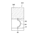
図5は、微細化ユニット30の入口側の端面板304を示す斜視図である。入口側の端面板304は円盤状をなし、中央部寄りの部分に複数の小径の貫通孔341,341,・・・が形成されている。これら貫通孔341,341,・・・は微細化ユニット30の入口開口として機能し、これら貫通孔341,341,・・・を有する端面板304は、微細化ユニット30の流路4への異物の流入を防止するフィルタとして機能する。端面板304の線対称位置には、2つのロッド孔342,342が形成されている。
FIG. 5 is a perspective view showing the
微細化ユニット30の出口側の端面板301は、中央に出口管305が貫通して設けられており、この出口管305は、ケーシング20の出口管25の内側に嵌合している。この出口管305により、微細化ユニット30がケーシング20に着脱可能に連結されている。出口側の端面板301には、出口管305の両側にロッド孔が形成されている。入口側の端面板304、端部ブロック302、5個の振動ブロック303,303,・・・、端部ブロック302及び出口側の端面板301の各々のロッド孔にロッド306,306が挿通されている。これらロッド306,306の両端に螺着したボルト307,307で出入口側の端面板301,304を対向方向に互いに圧迫して、微細化ユニット30の構成部材を互いに連結して固定している。
The
微細化ユニット30内には、5個の振動ブロック303,303,・・・と端部ブロック302が互いに連結されることにより、振動ブロック303,303,・・・の貫通孔41,41,・・・と端部ブロック302の内部が連通して、混合流体の流路4が形成されている。振動ブロック303の一端面に形成された有底孔の開口が、隣接する振動ブロック303又は入口側の端面板304で閉鎖されて、各振動ブロック303,303,・・・毎に気体溜り7,7,・・・が形成されている。これら気体溜り7,7,・・・は、各振動ブロック303,303,・・・毎に形成された連通路331,331,・・・を通して流路4に連通している。
In the
流路4を横断して各振動ブロック303,303,・・・毎に設けられたオリフィス振動部材5,5,・・・は、隣接するオリフィス振動部材5,5の間で、流通孔51の位置が軸方向視において異なるように配置されている。これにより、流路4に形成する混合流体の流れを適切に乱して、混合流体に含まれる気泡の微細化を促進するようになっている。
The
ケーシング20の内側面と、微細化ユニット30の外側面との間は、ケーシング20の入口開口20aから流入した混合流体で満たされるように形成されている。
The space between the inner side surface of the
ケーシング20の入口管24には、第1実施形態と同様に、空気と水を混合する前混合装置が接続されている。
Similarly to the first embodiment, a premixing device that mixes air and water is connected to the
上記微細化混合装置11は、次のように作動する。まず、前混合装置が起動し、気泡を含んだ水である混合流体が、図示しない供給管を経て入口開口20aに供給される。入口開口20aから入口管24を通ってケーシング20内に流入した混合流体は、ケーシング20の内側面と微細化ユニット30の外側面との間を満たした後、端面板304の貫通孔341,341,・・・から微細化ユニット30の内部に流入する。
The above-mentioned
微細化ユニット30内に流入した混合流体は、流路4を通過する過程で、気泡が微細化される。すなわち、混合流体が端部ブロック302内を通って振動ブロック303の貫通孔41に流入し、貫通孔41内に配置されたオリフィス振動部材5の流通孔51を通過する。このとき、オリフィス振動部材5の上下流の間に生成される圧力変化と流れの力により、オリフィス振動部材5の振動部53が振動し、この振動が混合流体に付与される。ここで、混合流体から分離した空気や作動当初に流路4に存在した空気が、流路4に連通する気体溜り7に溜まった状態で、流路4を混合流体が流れる。これにより、流路4を流れる混合流体の流れと圧力の変動に緩衝作用が付与される。上記オリフィス振動部材5の流通孔51を混合流体が通過する際の圧力及び流れの作用と、オリフィス振動部材5の振動部53の振動作用と、気体溜り7の緩衝作用が、5個の振動ブロック303,303,・・・によって混合流体に付与され、混合流体に含まれる気泡が効果的に微細化される。こうして微細化された気泡は、直径が10nm以上50μm以下のマイクロナノバブルとなり、このマイクロナノバブルを含む微細化混合流体は、微細化ユニット30の出口管305とケーシング20の出口管25を通って外部へ排出される。この微細化混合装置10は、直径が10nm以上50μm以下の空気のマイクロナノバブルを含んだ水を、約1〜50L/minの割合で生成する能力を有する。
The mixed fluid that has flowed into the
本実施形態の微細化混合装置10は、オリフィス振動部材5と気体溜り7を有する振動ブロック303が5個連なって形成された微細化ユニット30を備えるので、ナノバブルを含んだ微細化混合流体を効率良く生成することができる。また、気泡の微細化を行う部分であって、洗浄や補修の対象となる微細化ユニット30が、ケーシング20に対して着脱可能に形成されている。したがって、微細化ユニット30をケーシング20から取り外すことにより、微細化ユニット30の洗浄や補修を容易に行うことができる。
Since the refinement mixing apparatus 10 of the present embodiment includes the
さらに、微細化ユニット30は、端面板301,304、端部ブロック302及び振動ブロック303が、互いに分離可能に連結されて形成されている。したがって、端面板301,304及びブロック302,303を分離することにより、振動ブロック303のオリフィス振動部材5や気体溜り7に対して、容易に洗浄や補修を行うことができる。
Further, the
さらに、ケーシング2の内側面と微細化ユニット30の外側面との間が混合流体で満たされるので、動作時に微細化ユニット30からケーシング20に伝わる振動を緩和することができる。また、ケーシング2の内側面と微細化ユニット30の外側面との間の混合流体により、微細化ユニット30の内外の圧力差を少なくして、耐圧性を高めることができる。また、微細化ユニット30の内部から混合流体が漏れても、ケーシング2内で混合流体を回収することができるので、ケーシング2外への混合流体の漏れを防止できる。特に、微細化ユニット30を形成する端面板301,304やブロック302,303の連結部から混合流体が漏れても、漏れた混合流体を効果的に回収でき、また、ケーシング2外への混合流体の漏れを防止できる。
Furthermore, since the space between the inner side surface of the
また、微細化ユニット30を、オリフィス振動部材5及び気体溜り7を有する複数の振動ブロック303で構成するので、この振動ブロック303の個数を適宜変更することにより、混合流体の種類や、生成すべき気泡の寸法及び濃度に対応することができる。したがって、共通の部品を用いることにより、安価でありながら汎用性の高い微細化混合装置が得られる。
Further, since the
なお、ケーシング20の内側面と微細化ユニット30の外側面との間には、混合流体と共に、混合流体から分離した気体が溜まってもよい。すなわち、ケーシング20と微細化ユニット30との間には、気体溜りが形成されてもよい。
In addition, the gas isolate | separated from the mixed fluid may accumulate between the inner surface of the
(第3実施形態)
図6は、本発明の第3実施形態の微細化混合装置が備える微細化ユニット31を示す縦断面図である。この微細化ユニット31は、図示しないが、第2実施形態の微細化混合装置11のケーシング20と同じケーシングに装着されて微細化混合装置を形成する。本実施形態において、第2実施形態と同様の構成部分には同じ参照番号を引用して、詳細な説明を省略する。
(Third embodiment)
FIG. 6 is a longitudinal sectional view showing a
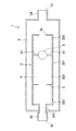
この微細化ユニット31は、2つの振動ブロック303,313と、3つの整流ブロック308,309,310を備える。2つの振動ブロック303,313と、2つの整流ブロック308,309は、気体溜り7と貫通孔41を有する同じ形状のブロック本体330を用いて形成されている。一方、1つの整流ブロック310は、他の整流ブロック308,309及び振動ブロック303,313と比較して、気体溜り7を有さないが、外径寸法が略同じに形成されている。
The
微細化ユニット31が備える一方の振動ブロック303は、第2実施形態の微細化ユニット30が備えるものと同様の構造を有し、ブロック本体330の貫通孔41に、1つのオリフィス振動部材5が配置されている。他方の振動ブロック313は、ブロック本体330の貫通孔41に、3つのオリフィス振動部材5が設けられている。図7は、他方の振動ブロック313を示す断面図であり、ブロック本体330の貫通孔41に、この貫通孔41の横断方向に延在するオリフィス振動部材5が、貫通孔41の軸方向に3つ配列されている。
One
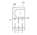
図8Aは、微細化ユニット31の第1の整流ブロック308を示す正面図であり、図8Bは、整流ブロック308の縦断面図である。この整流ブロック308は、ブロック本体330の貫通孔41に、双円錐形状の整流体62が配置されている。整流体62は、2つの同じ形状の円錐を底面同士で結合したような双円錐形状を有し、2つの尖端の間を結ぶ中心軸が、貫通孔41の軸と一致するように配置されている。整流体62は、軸方向の中央に形成された環状の峰から、貫通孔41の内側面に向かって径方向に延在する4つのアーム63,63,・・・により、貫通孔41内に固定されている。これにより、整流体62の外周面と、貫通孔41の内周面との間隔が、周方向において概ね均一に保持されている。
FIG. 8A is a front view showing the
図9は、微細化ユニット31の第2の整流ブロック309を示す縦断面図である。この整流ブロック309は、ブロック本体330の貫通孔41に、第1実施形態と同様の球状の整流体6が配置されている。この整流体6は、表面から貫通孔41の径方向に延びる棒状の4つのアーム61,61,・・・により、整流体6の表面と貫通孔41の内側面との間隔が周方向において概ね均一に保持された状態で、貫通孔41内に固定されている。
FIG. 9 is a longitudinal sectional view showing the
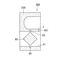
図10は、微細化ユニット31の第3の整流ブロック310を示す縦断面図である。この整流ブロック310は、有底孔による気体溜りを有しなくて、貫通孔41のみを有する大略円筒形状のブロック本体340を用いて形成されている。このブロック本体340の貫通孔41に、半球ドーム形状の整流体64が配置されている。この整流体64は、貫通孔41に形成される混合流体の流れの上流側に、半球ドームの頂点を向けた状態で、貫通孔内に固定されている。整流体64は、下流側の環状の縁から貫通孔41の径方向に延びる棒状の4つのアーム65,65,・・・により、整流体64の表面と貫通孔41の内側面との間隔が周方向において概ね均一に保持された状態で、貫通孔41内に固定されている。半球ドーム形状の整流体64は、貫通孔41内の流れの下流側に内部を開放している。この半球ドーム形状の整流体64の内部が、気体溜りを兼ねるようになっている。
FIG. 10 is a longitudinal sectional view showing the
微細化ユニット31は、図6に示すように、入口側の端面板304から出口側の端面板301に向かって順に、環状の端部ブロック302と、第1の整流ブロック308と、第2の整流ブロック309と、3つのオリフィス振動部材5を有する振動ブロック313と、第3の整流ブロック310と、1つのオリフィス振動部材5を有する振動ブロック303と、環状の端部ブロック302とが配列されて形成されている。これらのブロックに形成されたロッド孔にロッド306が挿通され、ロッド306の両端に螺着したボルト307によって出入口側の端面板301,304が対向方向に圧迫されて、微細化ユニット31の構成部材が互いに連結固定されている。この微細化ユニット31内には、上記入口側及び出口側の端部ブロック302,302の内部と、各ブロック308,309,313,310,303の貫通孔41が連通して、混合流体の流路4が形成されている。この流路4には、第3の整流ブロック310以外のブロック308,309,313,303に形成された気体溜り7が、各ブロックに形成された連通路331,331,・・・を介して連なっている。
As shown in FIG. 6, the
本実施形態の微細化ユニット31を有する微細化混合装置が作動すると、ケーシング20の入口開口20aからケーシング20内に、空気の泡が水に混合されてなる混合流体が供給され、この混合流体は、ケーシング20の内側面と微細化ユニット31の外側面との間を満たした後、端面板304の貫通孔341,341,・・・から微細化ユニット31の内部に流入する。
When the miniaturization mixing apparatus having the
微細化ユニット31内に流入した混合流体は、流路4を通過する過程で、気泡が微細化される。すなわち、まず、混合流体が端部ブロック302内を通って第1の整流ブロック308に流入し、貫通孔41の内側面と、双円錐形状の整流体62の外側面との間を流れる際に整流される。ここで、整流ブロック308の気体溜り7の緩衝作用により、混合流体が効果的に整流される。第1の整流ブロック308で整流された混合流体は、第2の整流ブロック309で更に整流され、振動ブロック313に流入する。振動ブロック313では、貫通孔41に設けられた3つのオリフィス振動部材5の流通孔51を混合流体が通過する際の圧力及び流れの作用と、オリフィス振動部材5の振動部53の振動作用と、気体溜り7の緩衝作用により、気泡が微細化される。気泡が微細化された混合流体は、第3の整流ブロック310で整流される。第3の整流ブロック310では、混合流体が半球ドーム形状の整流体64の外側面と、貫通孔41の内側面との間を流れる際に整流される。ここで、気体溜りを兼ねる半球ドーム形状の整流体64の内部に、混合流体から分離した気体が溜まり、これにより、流れと圧力の緩衝作用が混合流体へ与えられる。第3の整流ブロック310で整流された混合流体は、振動ブロック303で気泡が更に微細化され、微細化ユニット31の出口管305とケーシング20の出口管25を通って外部へ排出される。この微細化ユニット31を備える微細化混合装置は、直径が10nm以上50μm以下の空気のマイクロナノバブルを含んだ水を、約1〜50L/minの割合で生成する能力を有する。
The mixed fluid that has flowed into the
本実施形態の微細化混合装置の微細化ユニット31は、双円錐形状の整流体62と気体溜り7を有する整流ブロック308と、球形状の整流体6と気体溜り7を有する整流ブロック309とで整流を行った後、3つのオリフィス振動部材5と気体溜り7を有する振動ブロック313で微細化を行い、更に、内部が気体溜り7を兼ねる整流体64を有する整流ブロック310で整流を行った後、1つのオリフィス振動部材5と気体溜り7を有する振動ブロック303で微細化を行うので、水中の気泡を効果的に微細化して、ナノバブルを生成することができる。
The
なお、本実施形態の微細化混合装置は、ケーシング20と微細化ユニット31との間に、気体溜りが形成されてもよい。
In the refinement mixing apparatus of the present embodiment, a gas reservoir may be formed between the
(第4実施形態)
図11は、本発明の第4実施形態の微細化混合装置12を示す縦断面図である。この微細化混合装置12は、液体としての水の中に分散された気体としての空気を微細化し、マイクロナノバブルを生成するものである。この微細化混合装置12は、第2実施形態の微細化混合装置11と同様のケーシング20内に、円筒形状の微細化ユニット35が着脱可能に取り付けられている。本実施形態において、第2実施形態と同様の構成部分には同じ参照番号を引用して、詳細な説明を省略する。
(Fourth embodiment)
FIG. 11 is a longitudinal sectional view showing a
この微細化混合装置12の微細化ユニット35は、入口側の端面板304と、出口側の端面板301との間に、複数のリングブロック350と振動ダイヤフラム352とで形成された複数の室357,357,・・・を備える。
The
図12は、リングブロック350を示す斜視図である。リングブロック350は、軸方向断面が矩形のリングで形成され、軸方向に延在するロッド孔351,351,・・・が周方向に等間隔をおいて4つ形成されている。
FIG. 12 is a perspective view showing the
図13は、有孔振動体としての振動ダイヤフラム352を示す斜視図である。振動ダイヤフラム352は、円盤状のダイヤフラム本体352に、偏心した位置に形成された円形の流通孔353と、この流通孔353の縁から放射状に形成された複数のスリット354,354,・・・を有する。これらスリット354,354,・・・は、流通孔353に関する点対称位置にあるものが、互いに長さが異なるように形成されている。ダイヤフラム本体352の流通孔353に隣接する部分であって、流通孔353の縁と、スリット354,354とで規定される略台形の部分は、流通孔353を混合流体が流れる際に振動する振動部355になっている。ダイヤフラム本体352には、法線方向に延在するロッド孔356,356,・・・が周方向に等間隔をおいて4つ形成されている。
FIG. 13 is a perspective view showing a
微細化ユニット35内の室357,357,・・・は、円筒形状を有し、周面がリングブロック350で区画され、端面が振動ダイヤフラム352又は端面板301,304で区画されている。室357,357,・・・は、入口側から出口側に向かって、3つの室毎に軸方向の長さが短く形成されている。すなわち、入口側の端面板304に近い3つの室357,357,357は3つのリングブロック350,350,350で形成され、これらより出口側に位置する3つの室357,357,357は2つのリングブロック350,350で形成され、これらより出口側に位置して端面板301に近い3つの室357,357,357は1つのリングブロック350で形成されている。これにより、入口側の端面板304から出口側の端面板301に向かうにつれて、3つの室357,357,357毎に容積が小さくなっている。
The
各室357,357,・・・の間の振動ダイヤフラム352の流通孔353は、微細化ユニット35の軸方向視において、隣接する振動ダイヤフラム352の間で異なる位置に配置されている。
The flow holes 353 of the
上記室357,357,・・・には、各振動ダイヤフラム352の流通孔353を通して互いに連通し、入口側の端面板304の貫通孔341,341,・・・から出口側の端面板301に設けられた出口管305に至る流路4が形成される。また、上記室357,357,・・・の内部には、流路4を流れる混合流体から分離した空気が上部に溜まるようになっている。すなわち、上記室357,357,・・・は、流路4と気体溜りを兼ねている。
The
本実施形態の微細化混合装置12が作動すると、ケーシング20の入口開口20aからケーシング20内に、空気の泡が水に混合されてなる混合流体が供給され、この混合流体は、ケーシング20の内側面と微細化ユニット35の外側面との間を満たした後、端面板304の貫通孔341,341,・・・から微細化ユニット35の内部に流入する。
When the
微細化ユニット35内に流入した混合流体は、流路4を通過する過程で、気泡が微細化される。すなわち、まず、端面板304に隣接する室357に流入した混合流体が、振動ダイヤフラム352の流通孔353を通り、出口側に隣接する室357に流入する。このとき、振動ダイヤフラム352の上下流の間に生成される圧力変化と流れの力により、振動ダイヤフラム352の振動部355が振動し、この振動が混合流体に付与される。ここで、混合流体から分離した空気や作動当初に流路4に存在した空気が、室357内の一部に溜まった状態で、流路4を混合流体が流れる。これにより、流路4を流れる混合流体の流れと圧力の変動に緩衝作用が付与される。上記振動ダイヤフラム352の流通孔353を混合流体が通過する際の圧力及び流れの作用と、振動ダイヤフラム352の振動部355の振動作用と、室357内の気体の緩衝作用が混合流体に付与され、混合流体の気泡が効果的に微細化される。混合流体は、入口側の端面板304から出口側の端面板301までの間の9つの室357,357,・・・を流れる間に微細化され、直径が10nm〜数10μmのマイクロナノバブルが生成される。こうして生成されたマイクロナノバブルを含む微細化混合流体は、微細化ユニット35の出口管305とケーシング2の出口管25を通って外部へ排出される。この微細化混合装置12は、直径が10nm以上50μm以下の空気のマイクロナノバブルを含んだ水を、約1〜50L/minの割合で生成する能力を有する。
The mixed fluid that has flowed into the
本実施形態の微細化混合装置12によれば、リングブロック350とダイヤフラム352を用いて、少ない種類の部品で微細化ユニット35を構成するので、コストダウンを行うことができる。また、微細化ユニット35の構造が簡単であるので、故障を少なくできる。また、微細化ユニット35は、リングブロック350とダイヤフラム352に分離できるので、洗浄や補修を容易に行うことができる。また、所定の室357を形成するリングブロック350の個数を調整することにより、微細化ユニット35に設ける室357の数や容量を適宜設定することができる。したがって、微細化混合装置12の性能を、混合流体の種類や、微細化すべき流体の量に応じて設定することができ、高い汎用性の微細化混合装置12が得られる。
According to the
なお、本実施形態の微細化混合装置12は、ケーシング20と微細化ユニット35との間に、気体溜りが形成されてもよい。
In the
(第5実施形態)
図14は、本発明の第5実施形態の微細化混合装置13を示す縦断面図である。この微細化混合装置13は、液体としての水の中に分散された気体としての空気を微細化し、マイクロナノバブルを生成するものである。この微細化混合装置13は、第2実施形態の微細化混合装置11と同様のケーシング20内に、円筒形状の微細化ユニット36が着脱可能に取り付けられている。本実施形態において、第2実施形態と同様の構成部分には同じ参照番号を引用して、詳細な説明を省略する。
(Fifth embodiment)
FIG. 14 is a longitudinal sectional view showing a
この微細化混合装置13の微細化ユニット36は、入口側の端面板304と、出口側の端面板301との間に、整流体361と振動ダイヤフラム362を有する整流振動ブロック360が5個配列されて形成されている。なお、微細化ユニット36を構成する整流振動ブロック360の数は、5個以外であってもよい。整流振動ブロック360は、筒状のブロック本体内に、整流体361と振動ダイヤフラム362が同軸に配置されている。配列された整流振動ブロック360のブロック本体内に、混合流体の流路4が形成される。
In the
整流体361は半球ドーム形状を有し、ブロック本体内に軸方向に形成される混合流体の流れの上流側に、半球ドームの頂点を向けた状態で配置されている。整流体361は、半球ドームの内側に、軸方向に延びるスリーブが形成されており、このスリーブに挿通されるロッド306によって、ブロック本体内に保持されている。半球ドーム形状の整流体361は、ブロック本体内に形成される混合流体の流れの下流側に、内部を開放している。この半球ドーム形状の整流体361の内部が、気体溜りを兼ねるようになっている。
The rectifying
図15は、有孔振動体としての振動ダイヤフラム362を示す斜視図である。振動ダイヤフラム362は、円盤状のダイヤフラム本体362に、このダイヤフラム本体362と同心の円形の貫通孔363が形成されている。この貫通孔363の縁から、複数のスリット364,364,・・・が放射状に形成されている。これらスリット364,364,・・・は、貫通孔363に関する点対称位置にあるものが、互いに長さが異なるように形成されている。ダイヤフラム本体362の貫通孔363に隣接する部分であって、貫通孔363の縁と、スリット364,364とで規定される略台形の部分は、貫通孔363を混合流体が流れる際に振動する振動部365になっている。この貫通孔363内に、整流体361を保持するロッド306とスペーサ363が、貫通孔363の内周面と隙間をおいた状態で挿通されて配置される。
FIG. 15 is a perspective view showing a
微細化ユニット36の入口側の端面板304には、中央にロッド孔が形成され、このロッド孔の回りに、微細化ユニット36の入口開口である複数の貫通孔341,341,・・・が形成されている。
A rod hole is formed at the center of the
微細化ユニット36の出口側の端面板301には、中央にロッド孔が形成され、このロッド孔の回りに複数の貫通孔343,343,・・・が形成されていると共に、これら貫通孔343,343,・・・を取り囲むように出口管305が連結されている。出口管305は、ケーシング20の出口管25の内側に嵌合しており、この出口管305により、微細化ユニット36がケーシング20に着脱可能に連結されている。
In the
入口側の端面板304と、出口側の端面板301との間に5つの整流振動ブロック360が配列され、入口側の端面板304の中央と出口側の端面板301のロッド孔に、ロッド306が挿通されている。ロッド306には、整流振動ブロック360毎に、整流体361と、スリーブ状のスペーサ363とが装着される。このスペーサ363により、隣り合う整流体361を軸方向の所定位置に保持するようになっている。上記ロッド306の両端に螺着したボルト307,307で出入口側の端面板301,304を対向方向に互いに圧迫して、ブロック本体を互いに連結して固定している。
Five rectifying vibration blocks 360 are arranged between the
本実施形態の微細化混合装置13が作動すると、ケーシング20の入口開口20aからケーシング20内に、空気の泡が水に混合されてなる混合流体が供給され、この混合流体は、ケーシング20の内側面と微細化ユニット36の外側面との間を満たした後、端面板304の貫通孔341,341,・・・から微細化ユニット36の内部に流入する。
When the
微細化ユニット36内に流入した混合流体は、流路4を通過する過程で、気泡が微細化される。すなわち、まず、端面板304に隣接する整流振動ブロック360内に流入した混合流体が、半球ドーム形状の整流体361の外側面と、ブロック本体の内側面との間を流れる際に整流される。ここで、半球ドーム形状の整流体361の内部に、混合流体から分離した気体が溜まり、これにより、流れと圧力の緩衝作用が混合流体へ与えられて、混合流体が効果的に整流される。整流体361で整流された混合流体は、振動ダイヤフラム362の貫通孔363の縁と、スペーサ363の外周面との間を流れ、このときに振動ダイヤフラム362の上下流の間に生成される圧力変化と流れの力により、振動ダイヤフラム362の振動部365が振動し、この振動が混合流体に付与される。この混合流体の圧力及び流れの作用と、振動ダイヤフラム362の振動部365の振動作用と、整流体361の内部の気体による緩衝作用により、気泡が微細化され、直径が10nm〜数10μmのマイクロナノバブルが生成される。こうして生成されたマイクロナノバブルを含む微細化混合流体は、出口側の端面板301の貫通孔343,343,・・・から出口管305に流出し、この出口管305とケーシング2の出口管25を通って外部へ排出される。この微細化混合装置13は、直径が10nm以上50μm以下の空気のマイクロナノバブルを含んだ水を、約1〜50L/minの割合で生成する能力を有する。
The mixed fluid that has flowed into the
本実施形態の微細化混合装置13によれば、整流体361と振動ダイヤフラム362を有する整流振動ブロック360を複数個用いて微細化ユニット36を構成するので、同一の構造の整流振動ブロック360を用いて比較的安価に、しかも、効果的にマイクロナノバブルを生成することができる。また、整流振動ブロック360は、中心軸まわりに回転対称の形状を有するので、微細化混合装置13の設置姿勢を中心軸まわりの任意の方向に設定することができる。したがって、微細化混合装置13を容易に設置でき、また、車両等のような重力の作用方向が変動する環境に設置しても、安定して作動することができる。このため、本実施形態の微細化混合装置13は、車両に搭載され、例えば水と軽油を混合して水又は軽油を微細化して燃料を生成する用途に用いることができる。
According to the
本実施形態の微細化混合装置13は、入口開口20aを上側に向けると共に出口開口20bを下側に向けて、ケーシング20の中心軸が概ね鉛直方向に延在する姿勢で用いられるのが好ましい。これにより、半球ドーム形状の整流体361の内部に効果的に気体を溜めることができ、混合流体の流れと圧力の緩衝作用を効果的に発揮することができる。なお、微細化混合装置13が重力の作用方向が変動する環境に設置される場合、ケーシング20の中心軸が概ね鉛直方向に一定の割合で保持されればよく、常に鉛直方向に保持されなくてもよい。
The
また、本実施形態の微細化混合装置13によれば、微細化ユニット36が、個々の整流振動ブロック360に分離できるので、洗浄や補修を容易に行うことができる。また、微細化ユニット36を構成する整流振動ブロック360の個数を調整することにより、微細化混合装置13の性能を、混合流体の種類や、微細化すべき流体の量に応じて設定することができ、高い汎用性の微細化混合装置13が得られる。
Further, according to the
なお、本実施形態の微細化混合装置13は、ケーシング20と微細化ユニット36との間に、気体溜りが形成されてもよい。
In the
(第6実施形態)
図16は、本発明の第6実施形態の微細化混合装置14を示す縦断面図である。この微細化混合装置14は、液体としての水の中に分散された気体としての空気を微細化し、マイクロナノバブルを生成するものである。この微細化混合装置14は、第2実施形態の微細化混合装置11と同様のケーシング20内に、微細化ユニット37が着脱可能に取り付けられている。本実施形態において、第2実施形態と同様の構成部分には同じ参照番号を引用して、詳細な説明を省略する。
(Sixth embodiment)
FIG. 16 is a longitudinal sectional view showing a
この微細化混合装置14の微細化ユニット37は、入口側の端面仕切板377と、出口側の端面連結板376との間に、両端の接続管378,378を介して5個の緩衝ブロック370,370,・・・が配列されて固定されている。なお、微細化ユニット37を構成する緩衝ブロック370の数は、5個以外であってもよい。接続管378と緩衝ブロック370との間と、緩衝ブロック370,370の相互の間には、有孔振動体としての振動ダイヤフラム375,375,・・・が挟持されている。
The
入口側の端面仕切板377は、ケーシング20の端面板22に対向して、ケーシング20の内部を軸直角方向に横断するように配置されている。端面仕切板377は、概ね中央に形成されたロッド孔と、このロッド孔のまわりに形成された複数の内周側貫通孔377a,377a,・・・と、内周側貫通孔377a,377a,・・・の外側を取り囲むように形成された外周側貫通孔377b,377b,・・・を有する。端面仕切板377のケーシング2の対面板22と反対側の面に、微細化ユニット37の接続管378が連なっており、この接続管378の内側に、内周側貫通孔377a,377a,・・・が開口している。
The entrance-side end
出口側の端面連結板376は、ケーシング20の出口管25の内側の先端に連結されており、出口管25の内部に臨む位置に、ロッド孔と、複数の貫通孔376a,376a,・・・が形成されている。端面連結板376の出口管25と反対側の面に、微細化ユニット37の接続管378が連なっており、この接続管378の内側に、貫通孔376a,376a,・・・が開口している。
An end
微細化ユニット37の接続管378は、径方向よりも軸方向の寸法が短い短管で形成され、軸方向の両端にフランジが形成されている。緩衝ブロック370は、ケーシング20の軸方向に延在する流路管部371と、流路管部371の側面から径方向に突出する緩衝管部372を有する。緩衝環部372は、中心軸が流路管部371の中心軸と直角に延在する短管で形成され、先端が閉鎖されている。緩衝ブロック370内には、流路管部371の中心軸の延長線と、緩衝環部372の中心軸との交点に中心が位置するように、球状の整流体373が配置されている。整流体373は、径方向に延びる貫通孔を有し、この貫通孔に挿通されたロッド306によって保持されている。
The connecting
振動ダイヤフラム375は、第5実施形態の振動ダイヤフラム362と同様に、円盤状のダイヤフラム本体に同心の円形の貫通孔を有し、この貫通孔の縁から、複数のスリットが放射状に形成されている。これらスリットは、貫通孔に関する点対称位置にあるものが、互いに長さが異なるように形成されている。ダイヤフラム本体の貫通孔に隣接する部分であって、貫通孔の縁と、スリットとで規定される略台形の部分が、貫通孔を混合流体が流れる際に振動する振動部になっている。この貫通孔内に、整流体373を保持するロッド306と図示しないスリーブ状のスペーサ379が、貫通孔の内周面と隙間をおいた状態で挿通されて配置される。
Like the
入口側の端面仕切板377と出口側の端面連結板376との間に接続管378と緩衝ブロック370と振動ダイヤフラム375を配列し、各緩衝ブロック370内に整流体373を配置した状態で、端面仕切板377のロッド孔と、整流体373の貫通孔と、スペーサ379の内部と、端面連結板376のロッド孔とにロッド306が挿通される。このロッド306の両端に螺着したボルト307,307で端面仕切板377と端面連結板376を対向方向に互いに圧迫して、接続管378と緩衝ブロック370と振動ダイヤフラム375を互いに連結して固定している。互いに固定された接続管378の内部と、緩衝ブロック370の流通管部371の内部に、混合流体の流路4が形成される。
In the state where the connecting
本実施形態の微細化混合装置14が作動すると、ケーシング20の入口開口20aから入口管24に、空気の泡が水に混合されてなる混合流体が供給される。入口管24に供給された混合流体は、端面仕切板377の内周側貫通孔377aを通って微細化ユニット37に流入すると共に、端面仕切板377の外周側貫通孔377bを通って微細化ユニット37の外側面とケーシング20の胴部21の内側面との間に流入する。
When the
微細化ユニット37に流入した混合流体は、流路4を通過する過程で、気泡が微細化される。すなわち、まず、端面仕切板377から接続管378に流入した混合流体は、接続管378に隣接する振動ダイヤフラム375の貫通孔の縁と、スペーサ379の外周面との間を流れ、このときに振動ダイヤフラム375の上下流の間に生成される圧力変化と流れの力により、振動ダイヤフラム375の振動部365が振動し、この振動が混合流体に付与される。この混合流体の圧力及び流れの作用と、振動ダイヤフラム375の振動部の振動作用により、気泡が微細化される。振動ダイヤフラム375で微細化された混合流体は、緩衝ブロック370内に流入する。ここで、混合流体から分離した空気や作動当初に流路4に存在した空気が、緩衝管部372に溜まることにより、混合流体の流れと圧力の変動に緩衝作用が付与される。緩衝ブロック370内に流入した混合流体は、球状の整流体373の外周側を流れる際に整流され、この後、下流側の振動ダイヤフラム375に導かれて微細化される。緩衝ブロック370において、整流体373による整流効果と、振動ダイヤフラム375による微細化が、緩衝管部372の空気の緩衝作用によって促進される。混合流体が5つの緩衝ブロック370を流れるに伴い、気泡の直径が10nm〜数10μmに微細化されてマイクロナノバブルが生成される。こうして生成されたマイクロナノバブルを含む微細化混合流体は、出口側の端面連結板376の貫通孔376a,376a,・・・からケーシング2の出口管25に流出して外部へ排出される。この微細化混合装置14は、直径が10nm以上50μm以下の空気のマイクロナノバブルを含んだ水を、約1〜50L/minの割合で生成する能力を有する。
The mixed fluid that has flowed into the
本実施形態の微細化混合装置14によれば、整流体373を有する緩衝ブロック370と振動ダイヤフラム375を交互に連ねて微細化ユニット37を構成するので、同一の構造の緩衝ブロック370及び振動ダイヤフラム375を複数個用いて比較的安価に、しかも、効果的にマイクロナノバブルを生成することができる。
According to the
また、本実施形態の微細化混合装置14によれば、微細化ユニット37が、個々の緩衝ブロック370と振動ダイヤフラム375に分離できるので、洗浄や補修を容易に行うことができる。また、微細化ユニット37を構成する緩衝ブロック370と振動ダイヤフラム375の個数を調整することにより、微細化混合装置14の性能を、混合流体の種類や、微細化すべき流体の量に応じて設定することができ、高い汎用性の微細化混合装置14が得られる。
Further, according to the
なお、本実施形態の微細化混合装置14は、ケーシング20と微細化ユニット37との間に、気体溜りが形成されてもよい。
Note that, in the
上記第1乃至第6実施形態の微細化混合装置は、混合流体として、媒体の液体としての水の中に混合された気体としての空気を微細化し、マイクロナノバブルを生成したが、他の液体に他の気体が混合された混合流体に対し、気体を微細化してもよい。また、媒体の液体に、他の液体が混合された混合流体に対し、いずれかの液体を微細化してもよい。 The micronization mixing apparatus of the first to sixth embodiments generates micro / nano bubbles by micronizing air as a gas mixed in water as a liquid of a medium as a mixed fluid. You may refine | miniaturize gas with respect to the mixed fluid with which other gas was mixed. Further, any liquid may be refined with respect to a mixed fluid in which another liquid is mixed with the liquid of the medium.
媒体の液体に他の液体が混合された混合流体としては、水に油が混合された混合流体を例示することができ、この混合流体の水又は油を微細化して、水と油のエマルションを形成することができる。本発明の微細化混合装置で形成された水と油のエマルションは、ディーゼルエンジン、タービンエンジン又はボイラー等の燃料として用いることができる。本発明の微細化混合装置は、動力により駆動される部分が無いので、故障が少なく、また、分解が容易であり、清浄や補修が容易である。したがって、エンジンやボイラ等の燃料供給機構のコスト削減と、メンテナンス性の向上を図ることができる。 Examples of the mixed fluid in which another liquid is mixed with the liquid of the medium include a mixed fluid in which oil is mixed with water. The water or oil of the mixed fluid is refined to form an emulsion of water and oil. Can be formed. The water-oil emulsion formed by the fine mixing device of the present invention can be used as a fuel for diesel engines, turbine engines, boilers and the like. Since the miniaturized mixing apparatus of the present invention has no portion driven by power, there are few failures, it is easy to disassemble, and cleaning and repair are easy. Therefore, it is possible to reduce the cost of the fuel supply mechanism such as the engine and the boiler and improve the maintainability.
また、本発明の微細化混合装置によって生成され、マイクロナノバブルを含む混合流体は、微細化された気体に応じて種々の処理用途に供することができる。例えば、微細化された空気を含む混合液は、処理対象に添加することにより、湖沼や河川の水質浄化や、下水処理や、水産業の養殖の促進や、農業の水耕栽培や、農業用水の浄化に用いることができる。また、微細化されたオゾンを含む混合液は、工業排水処理や、部品洗浄や、食品廃液の浄化等に用いることができる。 Moreover, the mixed fluid containing the micro / nano bubbles generated by the miniaturization mixing apparatus of the present invention can be used for various processing applications depending on the miniaturized gas. For example, a liquid mixture containing fine air can be added to the treatment target to purify water quality in lakes and rivers, sewage treatment, promotion of aquaculture in agriculture, hydroponics in agriculture, and agricultural water. It can be used for purification. Moreover, the liquid mixture containing refined ozone can be used for industrial wastewater treatment, parts cleaning, purification of food waste liquid, and the like.
また、本発明の微細化混合装置は、媒体の液体に固体が混合された混合流体に対し、固体を微細化して微細化混合流体を生成することもできる。このような混合流体として、媒体の水に有機固形物が混合された有機汚泥がある。本発明の微細化混合装置によれば、有機汚泥の有機固形物を微細化して水中に分散させ、有機固形物の凝集を促進することができる。この種の混合流体の他の例としては、うどん等の食品の煮汁のような、食品廃水を挙げることができる。 Moreover, the refined mixing apparatus of the present invention can also produce a refined mixed fluid by refining a solid with respect to a mixed fluid in which a solid is mixed with a liquid of a medium. As such a mixed fluid, there is organic sludge in which organic solids are mixed with water of a medium. According to the refined mixing apparatus of the present invention, organic solids of organic sludge can be refined and dispersed in water to promote aggregation of organic solids. Other examples of this type of mixed fluid include food wastewater such as boiled food such as udon.
1 微細化混合装置
2 ケーシング
3 微細化ユニット
4 流路
5 オリフィス振動部材
6 整流体
DESCRIPTION OF SYMBOLS 1
Claims (9)
混合流体の入口と出口を有するケーシングと、このケーシング内に着脱可能に取り付けられた微細化ユニットとを備え、
上記微細化ユニットは、
上記ケーシングの入口から流入した混合流体を出口に向かって流す流路と、
上記流路の途中に設置され、上記流路の断面積よりも小さい断面積を有する流通孔と、この流通孔に隣接して形成され、混合流体の流れによって振動する振動部とを有する有孔振動体と、
上記流路に連通し、混合流体から分離した気体が溜まる気体溜りと
を有し、
上記微細化ユニットは、上記有孔振動体及び気体溜りの少なくとも一方が形成された複数のブロックで形成され、
上記有孔振動体及び空気溜りの両方が形成されたブロックは、
大略円筒形状のブロック本体と、
上記ブロック本体の中心軸と平行に延在して上記流路を形成する貫通孔と、
上記ブロック本体の一方の端面に形成されて上記貫通孔と平行に延在する有底孔と、この有底孔と上記貫通孔とを連通するバイパス路とを含んで形成された上記気体溜りと、
上記貫通孔の途中に設置された上記有孔振動体とを有することを特徴とする微細化混合装置。 A refined mixing apparatus that is supplied with a mixed fluid in which a gas, a liquid, or a solid is mixed with a liquid and that refines at least one gas, liquid, or solid contained in the mixed fluid to generate a refined mixed fluid,
A casing having an inlet and an outlet for the mixed fluid, and a miniaturization unit detachably mounted in the casing,
The miniaturization unit is
A flow path for flowing the mixed fluid flowing in from the inlet of the casing toward the outlet;
A perforated hole installed in the middle of the flow path and having a cross-sectional area smaller than the cross-sectional area of the flow path, and a vibrating part that is formed adjacent to the flow hole and vibrates by the flow of the mixed fluid A vibrating body,
Communicates with the flow path, possess a gas reservoir which separated gas is accumulated from the mixed fluid,
The miniaturization unit is formed of a plurality of blocks in which at least one of the perforated vibrator and the gas reservoir is formed,
The block in which both the perforated vibrator and the air pocket are formed is
A generally cylindrical block body;
A through hole extending parallel to the central axis of the block body to form the flow path;
The gas reservoir formed including a bottomed hole formed on one end face of the block body and extending in parallel with the through hole, and a bypass passage communicating the bottomed hole and the through hole. ,
A fine mixing device having the perforated vibrating body installed in the middle of the through hole .
混合流体の入口と出口を有するケーシングと、このケーシング内に着脱可能に取り付けられた微細化ユニットとを備え、
上記微細化ユニットは、
上記ケーシングの入口から流入した混合流体を出口に向かって流す流路と、
上記流路の途中に設置され、上記流路の断面積よりも小さい断面積を有する流通孔と、この流通孔に隣接して形成され、混合流体の流れによって振動する振動部とを有する有孔振動体と、
上記流路に連通し、混合流体から分離した気体が溜まる気体溜りと
を有し、
上記微細化ユニットは、入口側の端面板と、出口側の端面板との間に、複数のリング状のブロックと有孔振動体で形成された複数の室を有し、これら複数の室は、周面が上記ブロックで区画され、かつ、端面が有孔振動体又は端面板で区画されると共に、ブロックを連ねる数を異ならせて入口側から出口側に向かって軸方向の長さが短く形成され、上記流路と気体溜りを兼ねていることを特徴とする微細化混合装置。 A refined mixing apparatus that is supplied with a mixed fluid in which a gas, a liquid, or a solid is mixed with a liquid and that refines at least one gas, liquid, or solid contained in the mixed fluid to generate a refined mixed fluid,
A casing having an inlet and an outlet for the mixed fluid, and a miniaturization unit detachably mounted in the casing,
The miniaturization unit is
A flow path for flowing the mixed fluid flowing in from the inlet of the casing toward the outlet;
A perforated hole installed in the middle of the flow path and having a cross-sectional area smaller than the cross-sectional area of the flow path, and a vibrating part that is formed adjacent to the flow hole and vibrates by the flow of the mixed fluid A vibrating body,
A gas reservoir that communicates with the flow path and stores a gas separated from the mixed fluid;
The above-mentioned miniaturization unit has a plurality of chambers formed of a plurality of ring-shaped blocks and a perforated vibrator between an end surface plate on the inlet side and an end surface plate on the outlet side. The peripheral surface is partitioned by the block, and the end surface is partitioned by a perforated vibrating body or an end face plate, and the length in the axial direction is shortened from the inlet side to the outlet side by varying the number of blocks. A miniaturized mixing apparatus which is formed and serves as both a flow path and a gas reservoir.
混合流体の入口と出口を有するケーシングと、このケーシング内に着脱可能に取り付けられた微細化ユニットとを備え、
上記微細化ユニットは、
上記ケーシングの入口から流入した混合流体を出口に向かって流す流路と、
上記流路の途中に設置され、上記流路の断面積よりも小さい断面積を有する流通孔と、この流通孔に隣接して形成され、混合流体の流れによって振動する振動部とを有する有孔振動体と、
上記流路に連通し、混合流体から分離した気体が溜まる気体溜りと
を有し、
上記微細化ユニットは、入口側の端面板と、出口側の端面板との間に、筒状のブロックを複数個配列して形成され、
上記ブロックは、整流体と有孔振動体が同軸に配置されて内部に流路が形成され、
上記整流体は、半球ドーム形状を有し、上記ブロック本体内に軸方向に形成される混合流体の流れの上流側に半球ドームの頂点を向けた状態で配置され、かつ、上記混合流体の流れの下流側に半球ドームの内部を開放し、この半球ドーム形状の整流体の内部が気体溜りを兼ねていることを特徴とする微細化混合装置。 A refined mixing apparatus that is supplied with a mixed fluid in which a gas, a liquid, or a solid is mixed with a liquid and that refines at least one gas, liquid, or solid contained in the mixed fluid to generate a refined mixed fluid,
A casing having an inlet and an outlet for the mixed fluid, and a miniaturization unit detachably mounted in the casing,
The miniaturization unit is
A flow path for flowing the mixed fluid flowing in from the inlet of the casing toward the outlet;
A perforated hole installed in the middle of the flow path and having a cross-sectional area smaller than the cross-sectional area of the flow path, and a vibrating part that is formed adjacent to the flow hole and vibrates by the flow of the mixed fluid A vibrating body,
Communicates with the flow path, possess a gas reservoir which separated gas is accumulated from the mixed fluid,
The miniaturization unit is formed by arranging a plurality of cylindrical blocks between the end face plate on the inlet side and the end face plate on the outlet side,
In the block, the flow straightening body and the perforated vibrator are arranged coaxially to form a flow path inside,
The rectifying body has a hemispherical dome shape, is arranged with the apex of the hemispherical dome facing the upstream side of the flow of the mixed fluid formed in the axial direction in the block body, and the flow of the mixed fluid A hemispherical dome is opened on the downstream side of the dome, and the inside of the hemispherical dome-shaped rectifier also serves as a gas reservoir .
混合流体の入口と出口を有するケーシングと、このケーシング内に着脱可能に取り付けられた微細化ユニットとを備え、
上記微細化ユニットは、
上記ケーシングの入口から流入した混合流体を出口に向かって流す流路と、
上記流路の途中に設置され、上記流路の断面積よりも小さい断面積を有する流通孔と、この流通孔に隣接して形成され、混合流体の流れによって振動する振動部とを有する有孔振動体と、
上記流路に連通し、混合流体から分離した気体が溜まる気体溜りと
を有し、
上記微細化ユニットは、入口側の端面仕切板と、出口側の端面連結板との間に、複数のブロックが配列され、
上記複数のブロックの相互の間に有孔振動体が挟持され、
上記ブロックは、上記ケーシングの軸方向に延在する流路管部と、流路管部の側面から径方向に突出する緩衝管部を有し、この緩衝管部は、中心軸が流路管部の中心軸と直角に延在する短管で形成され、先端が閉鎖されており、
上記ブロック内に、上記流路管部の中心軸と上記緩衝管部の中心軸との交点に中心が位置するように、球状の整流体が配置されており、
上記緩衝管部が気体溜りとして作用することを特徴とする微細化混合装置。 A refined mixing apparatus that is supplied with a mixed fluid in which a gas, a liquid, or a solid is mixed with a liquid and that refines at least one gas, liquid, or solid contained in the mixed fluid to generate a refined mixed fluid,
A casing having an inlet and an outlet for the mixed fluid, and a miniaturization unit detachably mounted in the casing,
The miniaturization unit is
A flow path for flowing the mixed fluid flowing in from the inlet of the casing toward the outlet;
A perforated hole installed in the middle of the flow path and having a cross-sectional area smaller than the cross-sectional area of the flow path, and a vibrating part that is formed adjacent to the flow hole and vibrates by the flow of the mixed fluid A vibrating body,
Communicates with the flow path, possess a gas reservoir which separated gas is accumulated from the mixed fluid,
In the miniaturization unit, a plurality of blocks are arranged between the end face partition plate on the inlet side and the end face connecting plate on the outlet side,
A perforated vibrator is sandwiched between the plurality of blocks,
The block has a flow path pipe part extending in the axial direction of the casing and a buffer pipe part projecting in a radial direction from a side surface of the flow path pipe part. Formed with a short tube extending at right angles to the central axis of the part, the tip is closed,
In the block, a spherical rectifier is arranged so that the center is located at the intersection of the central axis of the flow path pipe part and the central axis of the buffer pipe part,
A miniaturized mixing apparatus, wherein the buffer tube part acts as a gas reservoir .
上記微細化ユニットは、上記流路に配置され、この流路の中心軸に関して回転体の形状に形成された整流体を有することを特徴とする微細化混合装置。 In the fine mixing apparatus according to claim 1,
The miniaturization unit is characterized in that the miniaturization unit includes a rectifier disposed in the flow path and formed in the shape of a rotating body with respect to the central axis of the flow path.
上記ケーシングの内側面と、上記微細化ユニットの外側面との間が、上記ケーシングの入口から流入した混合流体で満たされるように形成されていることを特徴とする微細化混合装置。 In the refinement | mixing mixing apparatus as described in any one of Claims 1 thru | or 4 ,
A miniaturizing and mixing apparatus, characterized in that a space between an inner side surface of the casing and an outer side surface of the miniaturizing unit is filled with a mixed fluid flowing from an inlet of the casing.
上記有孔振動体は、上記流路を横断するように配置された板状体で形成され、この板状体に形成された上記流通孔の縁から放射状に延びるスリットを有し、このスリットと流通孔の縁とで規定される部分が振動部となることを特徴とする微細化混合装置。 In the refinement | mixing mixing apparatus as described in any one of Claims 1 thru | or 4 ,
The perforated vibrator is formed of a plate-like body arranged so as to cross the flow path , and has slits extending radially from the edges of the flow holes formed in the plate-like body. miniaturization mixing device portion defined by the edge of the through channel, characterized the Turkey such as vibration unit.
上記整流体の形状は、球、双円錐及び半球ドームのうちの1つであることを特徴とする微細化混合装置。 In the refinement | mixing mixing apparatus of Claim 5 ,
The shape of the said rectification | straightening body is one of a sphere, a bicone, and a hemispherical dome, The fine mixing apparatus characterized by the above-mentioned.
上記整流体としての半球ドーム体の内側が、気体溜りとして機能することを特徴とする微細化混合装置。 In the miniaturization mixing apparatus of Claim 8 ,
An inside of a hemispherical dome as the rectifying body functions as a gas reservoir.
Priority Applications (1)
| Application Number | Priority Date | Filing Date | Title |
|---|---|---|---|
| JP2009190475A JP4901923B2 (en) | 2009-08-19 | 2009-08-19 | Refinement mixing equipment |
Applications Claiming Priority (1)
| Application Number | Priority Date | Filing Date | Title |
|---|---|---|---|
| JP2009190475A JP4901923B2 (en) | 2009-08-19 | 2009-08-19 | Refinement mixing equipment |
Publications (2)
| Publication Number | Publication Date |
|---|---|
| JP2011041880A JP2011041880A (en) | 2011-03-03 |
| JP4901923B2 true JP4901923B2 (en) | 2012-03-21 |
Family
ID=43829728
Family Applications (1)
| Application Number | Title | Priority Date | Filing Date |
|---|---|---|---|
| JP2009190475A Active JP4901923B2 (en) | 2009-08-19 | 2009-08-19 | Refinement mixing equipment |
Country Status (1)
| Country | Link |
|---|---|
| JP (1) | JP4901923B2 (en) |
Families Citing this family (2)
| Publication number | Priority date | Publication date | Assignee | Title |
|---|---|---|---|---|
| CN103084085B (en) * | 2012-11-14 | 2014-09-17 | 安徽铜都阀门股份有限公司 | Pipeline static mixer |
| PL423571A1 (en) * | 2017-11-24 | 2019-06-03 | Univ Technologiczno Przyrodniczy Im Jana I Jedrzeja Sniadeckich W Bydgoszczy | Construction of a mixer for mixing grainy material, with the vibratory round-screw driving system |
Family Cites Families (8)
| Publication number | Priority date | Publication date | Assignee | Title |
|---|---|---|---|---|
| JPS54141064A (en) * | 1978-04-25 | 1979-11-01 | Matsushita Electric Ind Co Ltd | Kitchen disposer |
| JP2663329B2 (en) * | 1993-09-01 | 1997-10-15 | 和泉電気株式会社 | Excess gas separation type gas-liquid pressurized reactor |
| JPH10328543A (en) * | 1997-06-02 | 1998-12-15 | Kankyo Kagaku Kogyo Kk | Still fluid mixer |
| JP4069211B2 (en) * | 2002-04-17 | 2008-04-02 | 財団法人くまもとテクノ産業財団 | Micro bubble production equipment |
| JP2006272091A (en) * | 2005-03-28 | 2006-10-12 | Matsushita Electric Works Ltd | Fine bubble producing apparatus |
| JP4863832B2 (en) * | 2006-10-13 | 2012-01-25 | エス・ピー・ジーテクノ株式会社 | Dispersion production method and dispersion production module |
| JP4479711B2 (en) * | 2006-11-02 | 2010-06-09 | Dic株式会社 | Method for producing aqueous polyurethane resin dispersion |
| JP2008279351A (en) * | 2007-05-10 | 2008-11-20 | Daiko:Kk | Fine bubble generator and apparatus for generating finn bubble |
-
2009
- 2009-08-19 JP JP2009190475A patent/JP4901923B2/en active Active
Also Published As
| Publication number | Publication date |
|---|---|
| JP2011041880A (en) | 2011-03-03 |
Similar Documents
| Publication | Publication Date | Title |
|---|---|---|
| RU2446869C2 (en) | Liquid ultrasound treatment chamber (versions) | |
| US20180178173A1 (en) | Nanobubble-producing apparatus | |
| JP2008018330A (en) | Bubble generating device | |
| JP2002263678A (en) | Device for producing water which contains fine air bubble | |
| US7600911B2 (en) | Water-mixing device, sand trap and method of using same | |
| JPWO2018117040A1 (en) | Apparatus and system for generating gas-liquid containing fine bubbles | |
| JP5143942B2 (en) | Refinement mixing equipment | |
| JP4901923B2 (en) | Refinement mixing equipment | |
| JP2011115674A (en) | Micronization mixer | |
| JP2011218343A (en) | Nozzle for gas-liquid mixing, gas-liquid mixing mechanism and application of the same | |
| JP3285427B2 (en) | Emulsion manufacturing apparatus and method | |
| JP2007253000A (en) | Apparatus and process for producing micro bubble | |
| WO2018151171A1 (en) | Bubble generating device for sewage purification | |
| JPH1066962A (en) | Sewage treating device | |
| JP4879232B2 (en) | Refinement mixing equipment | |
| JP2018130653A5 (en) | ||
| WO2018131714A1 (en) | Fluid mixing device, and method for producing mixed fluid using this mixing device | |
| JP2013237035A (en) | Gas dissolver | |
| JP5611387B2 (en) | Refinement mixing equipment | |
| JP5294434B2 (en) | Refinement mixing equipment | |
| RU2336123C1 (en) | Plate multi-channel cavitation reactor | |
| RU2576056C2 (en) | Mass-transfer apparatus | |
| RU198301U1 (en) | Vortex Jet Mixer | |
| RU32005U1 (en) | Ultrasonic Liquid Processing Device | |
| KR102616604B1 (en) | Nano-bubble generator |
Legal Events
| Date | Code | Title | Description |
|---|---|---|---|
| A977 | Report on retrieval |
Free format text: JAPANESE INTERMEDIATE CODE: A971007 Effective date: 20110819 |
|
| A131 | Notification of reasons for refusal |
Free format text: JAPANESE INTERMEDIATE CODE: A131 Effective date: 20110830 |
|
| A521 | Request for written amendment filed |
Free format text: JAPANESE INTERMEDIATE CODE: A523 Effective date: 20111031 |
|
| A131 | Notification of reasons for refusal |
Free format text: JAPANESE INTERMEDIATE CODE: A131 Effective date: 20111129 |
|
| A521 | Request for written amendment filed |
Free format text: JAPANESE INTERMEDIATE CODE: A523 Effective date: 20111207 |
|
| TRDD | Decision of grant or rejection written | ||
| A01 | Written decision to grant a patent or to grant a registration (utility model) |
Free format text: JAPANESE INTERMEDIATE CODE: A01 Effective date: 20111227 |
|
| A01 | Written decision to grant a patent or to grant a registration (utility model) |
Free format text: JAPANESE INTERMEDIATE CODE: A01 |
|
| A61 | First payment of annual fees (during grant procedure) |
Free format text: JAPANESE INTERMEDIATE CODE: A61 Effective date: 20111227 |
|
| R150 | Certificate of patent or registration of utility model |
Ref document number: 4901923 Country of ref document: JP Free format text: JAPANESE INTERMEDIATE CODE: R150 Free format text: JAPANESE INTERMEDIATE CODE: R150 |
|
| FPAY | Renewal fee payment (event date is renewal date of database) |
Free format text: PAYMENT UNTIL: 20150113 Year of fee payment: 3 |
|
| R250 | Receipt of annual fees |
Free format text: JAPANESE INTERMEDIATE CODE: R250 |
|
| R250 | Receipt of annual fees |
Free format text: JAPANESE INTERMEDIATE CODE: R250 |
|
| R250 | Receipt of annual fees |
Free format text: JAPANESE INTERMEDIATE CODE: R250 |
|
| R250 | Receipt of annual fees |
Free format text: JAPANESE INTERMEDIATE CODE: R250 |