JP4897812B2 - Improved baggage case - Google Patents
Improved baggage case Download PDFInfo
- Publication number
- JP4897812B2 JP4897812B2 JP2008528576A JP2008528576A JP4897812B2 JP 4897812 B2 JP4897812 B2 JP 4897812B2 JP 2008528576 A JP2008528576 A JP 2008528576A JP 2008528576 A JP2008528576 A JP 2008528576A JP 4897812 B2 JP4897812 B2 JP 4897812B2
- Authority
- JP
- Japan
- Prior art keywords
- case
- handle
- baggage
- wheel
- container
- Prior art date
- Legal status (The legal status is an assumption and is not a legal conclusion. Google has not performed a legal analysis and makes no representation as to the accuracy of the status listed.)
- Expired - Fee Related
Links
Images


Classifications
-
- A—HUMAN NECESSITIES
- A45—HAND OR TRAVELLING ARTICLES
- A45C—PURSES; LUGGAGE; HAND CARRIED BAGS
- A45C7/00—Collapsible or extensible purses, luggage, bags or the like
-
- A—HUMAN NECESSITIES
- A45—HAND OR TRAVELLING ARTICLES
- A45C—PURSES; LUGGAGE; HAND CARRIED BAGS
- A45C5/00—Rigid or semi-rigid luggage
- A45C5/14—Rigid or semi-rigid luggage with built-in rolling means
-
- A—HUMAN NECESSITIES
- A45—HAND OR TRAVELLING ARTICLES
- A45C—PURSES; LUGGAGE; HAND CARRIED BAGS
- A45C13/00—Details; Accessories
- A45C13/26—Special adaptations of handles
-
- A—HUMAN NECESSITIES
- A45—HAND OR TRAVELLING ARTICLES
- A45C—PURSES; LUGGAGE; HAND CARRIED BAGS
- A45C13/00—Details; Accessories
- A45C13/26—Special adaptations of handles
- A45C13/262—Special adaptations of handles for wheeled luggage
-
- A—HUMAN NECESSITIES
- A45—HAND OR TRAVELLING ARTICLES
- A45C—PURSES; LUGGAGE; HAND CARRIED BAGS
- A45C13/00—Details; Accessories
- A45C13/38—Luggage carriers
-
- A—HUMAN NECESSITIES
- A45—HAND OR TRAVELLING ARTICLES
- A45C—PURSES; LUGGAGE; HAND CARRIED BAGS
- A45C5/00—Rigid or semi-rigid luggage
- A45C5/14—Rigid or semi-rigid luggage with built-in rolling means
- A45C5/146—Rigid or semi-rigid luggage with built-in rolling means retractable
-
- A—HUMAN NECESSITIES
- A45—HAND OR TRAVELLING ARTICLES
- A45C—PURSES; LUGGAGE; HAND CARRIED BAGS
- A45C13/00—Details; Accessories
- A45C13/38—Luggage carriers
- A45C13/385—Luggage carriers with rolling means
-
- A—HUMAN NECESSITIES
- A45—HAND OR TRAVELLING ARTICLES
- A45C—PURSES; LUGGAGE; HAND CARRIED BAGS
- A45C7/00—Collapsible or extensible purses, luggage, bags or the like
- A45C7/0018—Rigid or semi-rigid luggage
- A45C7/0045—Rigid or semi-rigid luggage comprising a plurality of separable elements which can be used independently of one another
-
- A—HUMAN NECESSITIES
- A45—HAND OR TRAVELLING ARTICLES
- A45C—PURSES; LUGGAGE; HAND CARRIED BAGS
- A45C9/00—Purses, Luggage or bags convertible into objects for other use
-
- B—PERFORMING OPERATIONS; TRANSPORTING
- B62—LAND VEHICLES FOR TRAVELLING OTHERWISE THAN ON RAILS
- B62B—HAND-PROPELLED VEHICLES, e.g. HAND CARTS OR PERAMBULATORS; SLEDGES
- B62B3/00—Hand carts having more than one axis carrying transport wheels; Steering devices therefor; Equipment therefor
Description
本発明は、旅行者の手荷物ケースに関し、特に、床、歩道などを行くケースの移動を容易にするための車輪と押しハンドルとを備えた手荷物ケースに関する。 The present invention relates to a traveler's baggage case, and more particularly, to a baggage case provided with wheels and a push handle for facilitating movement of a case on a floor, a sidewalk, or the like.
過去数十年の間、人々は、より長い期間より遠い距離にわたって、より大きく且つより重いスーツケースを携えて旅行をするようになっている。空港、鉄道の駅、ホテル、あるいは他の場所で、手荷物を持ち上げ、手で運ぶのは、旅行者によって一般に嫌われる仕事である。レンタルの手荷物カートは、この種の或る場所において利用可能であるが、借りる手続そのものが不便であり、また、そのようなカートは、レンタルした場所を離れると旅行者の手元には残らない。この問題を緩和するために、それを操作したり、使用しないときに収納したりし易いように、軽くて折り畳み可能な構造の車付き手荷物キャリアが用いられている。そのようなキャリアの例が、図1に示されている。 During the past decades, people have traveled with larger and heavier suitcases over longer distances and longer distances. Lifting and carrying baggage at airports, railway stations, hotels, or other places is a task generally disliked by travelers. Rental baggage carts are available in some places of this type, but the borrowing procedure itself is inconvenient, and such carts do not remain in the hands of travelers once they leave the rental location. In order to alleviate this problem, a baggage carrier with a vehicle having a light and foldable structure is used so that it can be easily operated and stored when not in use. An example of such a carrier is shown in FIG.
そのようなキャリアは、手荷物ケースが載せられるような台と、台の一方のエッジ部に配置された一対の車輪と、その端部から上方に伸びたハンドルとを備えた、本質的に小さな手押し車型のものである。ユーザは、台と手荷物ケースとを下の床などから上方に持ち上げるために、ハンドルを握って傾け、その後、キャリアはケースの行き先に向けて引っぱられたり押されたりする。そのようなキャリア等は、助けにはなるが、そのもの自体の不便さからは完全に免れることはできない。キャリアは、自分から安定化することがなく、移動中に完全に自己支持するということができない。そのようなキャリアを引いたり押したりしている人は、キャリアが床やその他の表面を進むことができるように、キャリアを傾けた位置に保持する努力をずっとし続けなければならない。ユーザによるそのような努力がなければ、台やハンドルそのものが床に着くまで、重力がキャリアを回転することになる。 Such a carrier is essentially a small hand push with a platform on which a luggage case can be placed, a pair of wheels located on one edge of the platform, and a handle extending upward from the end. It is of a car type. The user grips and tilts the handle to lift the platform and baggage case up, such as from the lower floor, and then the carrier is pulled or pushed towards the destination of the case. Such a carrier is helpful but cannot be completely free from the inconvenience of itself. The carrier cannot stabilize itself and cannot fully support itself while moving. Those who are pulling or pushing such a carrier must continue to strive to hold the carrier in a tilted position so that the carrier can travel on the floor and other surfaces. Without such effort by the user, gravity will rotate the carrier until the platform or handle itself reaches the floor.
手荷物ケースがキャリアから取り除かれると、キャリアそのものは、本質的に、旅行者がなおも取り組まなければならない、手荷物から分離した他の1つの荷物である。そのようなキャリアを進む方向に傾けるときの不安定性や、ハンドルが離されたときに発生する回転運動などは、手荷物を持って小さな子供と共に移動するような目的には不満足なものである。 When the baggage case is removed from the carrier, the carrier itself is essentially one other piece of luggage separated from the baggage that the traveler must still work on. Such instability when tilting the carrier in the advancing direction and rotational movement that occurs when the handle is released are unsatisfactory for the purpose of moving with a small child with baggage.
過去二十年間にわたって、分離キャリアの助けなしにそれ自身で車輪移動できる手荷物ケースを作るための精力的な努力がなされ、今日では殆どのスーツケースが車輪付きとなっている。車輪付きケースは、一般に、そのケースが直立位置にあるとき下方に面しているケースのベース/底面に車輪を有している。車輪付きケースの設計は、一般に、2つの構造のうち1つとされる。第1のものは、従来の四角形の箱形スーツケースの狭い側の一端または両端の対向する角部に配置された車輪を有している。このような、配置方向のとき、ケースはその方向に沿って車輪移動でき、ケースは、実質的にその幅よりも高くなる。この形の車輪付きケースの一例が、図2に見られる。例えば、帯の輪のような引っ張り装置がケースの上部側端部の1つに備えられている。 Over the past two decades, strenuous efforts have been made to create a luggage case that can be wheeled on its own without the assistance of a separation carrier, and today most suitcases are wheeled. Wheeled cases generally have wheels on the base / bottom of the case facing downward when the case is in an upright position. The design of the wheeled case is generally one of two structures. The first has wheels disposed at opposite corners of one or both ends on the narrow side of a conventional rectangular box-shaped suitcase. In such an arrangement direction, the case can move along the direction of the wheel, and the case is substantially higher than its width. An example of this type of wheeled case can be seen in FIG. For example, a tensioning device, such as a belt ring, is provided at one of the upper end portions of the case.
このような構成の有利な点は、スーツケースを運んだり転がしたりする変化の容易性にあり、潜在能力として、歩くのに邪魔になることなく自分の横でスーツケースを転がすことができる。しかしながら、重大な欠点は、長く細いベースによる操縦特性の困難性や、ケースが一方や他方にぐらついて倒れそうになる傾向の原因となる細いベースと高い重心による不安定性にある。さらに、そのようなケースを引いている人は、一般に、引き具に届くように不安定な姿勢をして身体を傾けたり、かがんだりしなければならず、また、一般に、後ろのケースを引っ張っるためにとることのできる大股歩きのための空間が不十分となる。引き具を延長するのは、操舵性と安定性とを、より以上に危うくするので、まずい選択である。この理由により、そのような幾つかのケースは、広いベースを有する。しかしながら、ベースを広げることは、運ぶ際の角度を増大させ、手によってケースを運ぶことを、より人間工学特性に劣るものとし、より難儀にする。 The advantage of such a configuration is the ease of change in carrying and rolling the suitcase, and as a potential, the suitcase can be rolled next to it without disturbing walking. However, a serious drawback is the instability due to the difficulty of steering characteristics due to the long and thin base, and the thin base and high center of gravity that cause the case to tend to wobble to one or the other. In addition, a person pulling such a case must generally lean or lean over in an unstable posture to reach the puller, and generally pulls on the back case. Therefore, there is not enough space for the large-scale walking that can be taken. Extending the puller is a bad choice because it compromises steerability and stability. For this reason, some such cases have a wide base. However, widening the base increases the angle of carrying and makes carrying the case by hand less ergonomic and more difficult.
車輪付きケースの第2の共通の構成は、図3aに示されるように、カート構成として知られており、細いベースの一辺側にのみ設けられた車輪を有し、ケースの移動を容易とするために同じ側に作り込まれた格納式のハンドルバーを有している。ハンドルバーが伸長され、全体が、車輪の回りで傾けられ、上述した図1の手荷物ケースキャリアと本質的に同じ方法で操作される。このような配置の利点は、よりよい操作性と安定性、および改善された人間工学特性である。格納式ハンドルは、一般に使い易く、車輪上のケースを傾けることにより容易に使用状態とすることができる。しかしながら、そのような設計のものは、通行中に自己支持するものではなく、傾けた状態にそれを保つために、ユーザによる連続的な持ち上げ支持が求められる。それは、小さく軽いケースには適しているが、大きなサイズかつ/または重いスーツケースについての設計では、車輪で移動する場合に、そのかなりの大きさと重さのため、それを持ち回るのは煩わしく疲れるものである。実際、年取った体力のない人にとって、このような設計では、より小さく、より軽いケースでさえ、なお重荷となり、短い通行では重荷は大したことはないが、旅行が長引けばそのような重荷がうんざりするものとなり、ますます環境に飽きてその人をますます疲れさす。車輪付きケースのこのカート構成は、長い/細い面に車輪を備えたケースよりも、比較的、通行において安定であり、人間工学的であり、比較的操縦し易く、使用状態とすることが容易であるが、ユーザの手/腕が関節炎/不自由であったり機能障害であると、それを使うことは、それは通行中において自己支持ではないことから、重い負担を要し、長旅において一層困難なものとなる。大股歩きのための空間も1つの問題となり、また、ケースがラフな表面(例えば、道路)を通行する間、振動が手に伝わって感じられる。また、この車輪付き手荷物ケースの構成は、ケースの上に他の物品を積み上げるのを容易としない(上面における面積は狭く、支持車輪から離れた輸送用把手に近い位置に追加の荷物が置かれるので、全体の手荷物を重くする)。 The second common configuration of the wheeled case is known as a cart configuration, as shown in FIG. 3a, and has wheels provided only on one side of the thin base to facilitate the movement of the case. For this purpose, it has a retractable handlebar built on the same side. The handlebar is extended and the whole is tilted around the wheel and operated in essentially the same way as the baggage case carrier of FIG. 1 described above. The advantages of such an arrangement are better operability and stability, and improved ergonomic properties. The retractable handle is generally easy to use, and can be easily put into use by tilting the case on the wheel. However, such designs are not self-supporting during traffic, but require continuous lifting support by the user to keep it tilted. It is suitable for small and light cases, but in the design for large and / or heavy suitcases, it is bothersome and tiresome to carry around because of its considerable size and weight when moving on wheels Is. In fact, for those who are not physically fit, such a design is still a burden, even in smaller and lighter cases, and the burden is not significant in short traffic, but if the trip is prolonged, such a burden It becomes annoying and getting tired of the environment and getting tired more and more. This cart configuration with a wheeled case is relatively stable in traffic, ergonomic, relatively easy to maneuver and easy to use than a case with wheels on long / thin surfaces However, if the user's hand / arm is arthritis / handicapped or dysfunctional, using it is not self-supporting while on the road, so it takes a heavy burden and is more difficult on long trips It will be something. Large space for walking is also a problem, and vibrations are transmitted to the hand and felt while the case passes on a rough surface (for example, a road). Also, this wheeled baggage case configuration does not make it easy to stack other items on the case (the area on the top surface is small and additional baggage is placed close to the transport handle away from the support wheels. So make the whole baggage heavy).
上述の構成の普及している改良例は、スピナ構成として知られており、端部壁に多方向性車輪の組を有し、通常、その端部壁を水平にして転動される。この構成の車輪付き手荷物ケースは、自己支持であり、従って、旅行中の全時間にわたってケースを支持したり保持したりする必要性がなく、それは多方向移動/操舵ができ、使用状態にするのが容易である。しかしながら、それは、高い重心と、短い/狭い表面における車輪とを有し、従って、曲がり角や平坦でない地面において不安定であり、よろけ易い。それはまた、非人間工学的であり、従って、手首と腕に負担となる(例えば、重い荷物を載せて、例えば、絨毯や坂道を移動するとき)。やはり、ケースがラフな表面(例えば、道路)を通行する間、振動が手に伝わって感じられ、また、ケースの上に他の物品を積み上げるのを容易としない(上面における狭い面積)。 A popular improvement of the above configuration is known as the spinner configuration and has a set of multidirectional wheels on the end wall, usually rolling with the end wall horizontal. The wheeled baggage case of this configuration is self-supporting and therefore does not need to support or hold the case for the entire time during travel, it can be moved / steered in multiple directions and is in use. Is easy. However, it has a high center of gravity and wheels on short / narrow surfaces and is therefore unstable and prone to bends on corners and uneven ground. It is also non-ergonomic and therefore burdens the wrist and arm (eg when carrying heavy loads, eg moving on carpets or hills). Again, vibrations are felt in the hand while the case travels on rough surfaces (eg, roads), and does not make it easy to stack other items on the case (a small area on the top surface).
上述の全ての設計において、狭いベースと高い重心は、ケースが不安定であることを意味する。 In all the above designs, a narrow base and a high center of gravity mean that the case is unstable.
昔、1980年代に、スーツケースの表面が最も広い幅広面に車輪を設け、車輪上のこの最大幅の面に載ったケースをトロリーのように押す(引く)試みがなされた(米国特許No.6041900号、アウタリガ・インク参照)。これは、広い底部と低い重心を有しており、良い安定性を示した。しかしながら、持ち運びや収納の間に露出している車輪に対する潜在的な損傷、静止できないスーツケースへの詰め込みや取出し、という実用上の不便な点がある。また、そのようなケースを積み上げる際に、そのケースが一ヶ所に留まるということについて信頼できないので、例えば、飛行機や長距離バスの貨物倉が、ここでも、問題をはらむものとなる。幾人かは、車輪を使用するときにその展開した位置に車輪を保持するために一般に保持機構、例えば、キャッチやラッチを用いて車輪を格納式とすることを試みてきた。その1つの例が、米国特許No.5407039号、アルパ、トレベシックによって示され、下記の図3bに図解されている。 In the past, in the 1980s, an attempt was made to push (pull) the case on the widest surface on the wheel like a trolley by placing the wheel on the widest surface with the widest surface of the suitcase (US Pat. 6041900, see Outeriga, Inc.). It had a wide bottom and a low center of gravity and showed good stability. However, there are practical inconveniences such as potential damage to wheels exposed during carrying and storage, and packing and unloading into a suitcase that cannot be stationary. In addition, when stacking such cases, it is unreliable that the cases remain in one place, so for example, cargo holds for airplanes and long-distance buses are also problematic here. Some have attempted to make the wheel retractable, typically using a retention mechanism, such as a catch or latch, to hold the wheel in its deployed position when it is in use. One example is U.S. Pat. Shown by 54007039, Alpa, Trevethik and illustrated in Figure 3b below.
これらの従来設計の複数の格納式車輪は、弱くてもろく、扱いがやっかいで、使用したり格納したりするのが不便である。さらに、それらはケース全体を、実用目的としてはあまりにも重くしすぎる。ケースの重量はピボット点、および/または、車輪格納機構の支持ピンに集中するので、一般にその機構が壊れるのを防止するために、より強くより重い材料が求められ、ケースの全体の重量にさらに加算される。加えて、保持機構が、長い使用期間のしばしば重い重量をいつも支えることができるとは限らなく、このことは、保持機構の故障を招き、この種の手荷物ケースは、しばしば修繕したり、ちゃんとした底部に置き換えたりしなければならなくなる。これらの欠点の観点から、とりわけ、トロリーケースの構成は実用化に失敗し早々に放棄された。 These traditionally designed retractable wheels are weak and fragile, cumbersome and inconvenient to use and store. Furthermore, they make the entire case too heavy for practical purposes. Since the weight of the case is concentrated at the pivot point and / or the support pin of the wheel storage mechanism, generally a stronger and heavier material is required to prevent the mechanism from breaking, adding to the overall weight of the case. Is added. In addition, the retention mechanism is not always capable of supporting the often heavy weight of long periods of use, which leads to failure of the retention mechanism, and this type of baggage case is often repaired or decent Or replace it with the bottom. In view of these drawbacks, the construction of the trolley case failed to be put into practical use and was abandoned quickly.
手荷物ケース設計に対する最近の重要な改良に関し、我々は、出願者の同時係属の(従来公開されていない)出願に開示されているように、図4を参照して以下に示す手荷物ケースを提案した。このケースは、トロリーの方法で車輪を付けたものとされており、自己保持可能であり、低い重心と幅広いベースを有し、従って安定しており、よろけたりすることなくより操縦し易く、より人間工学的であり、荷物を引っ張るよりも押し易く(体重の使用)、ケースの上に他の手荷物を積み上げ易く(各ケースに可能最大面積、低重心と広いベースによる初期安定性)。しかしながら、追加の車輪と格納機構および多分割(4乃至5区分)の格納式押しハンドルと格納庫のために、ケースに対する余分の重量がある。操舵車輪組立体は、2段階で使用される(または1段階、しかし”カート”や”スピナ”よりも使用に際し若干の努力が必要)。その使用は、短い距離の移動にはかなりつまらないものであろう。このケースは、また、カートとしての機能が加えられるならカート機能のための別のハンドルが必要であろうし、重量も追加される。 With regard to recent significant improvements to baggage case design, we have proposed the baggage case shown below with reference to FIG. 4 as disclosed in applicant's co-pending (not previously published) application. . This case is wheeled in a trolley way, is self-holding, has a low center of gravity and a wide base, and is therefore stable, easier to steer without wobbling, more Ergonomic, easier to push than pull luggage (use of weight), easy to stack other baggage on top of case (maximum possible area for each case, low center of gravity and initial stability due to wide base). However, there is extra weight for the case due to the additional wheels and storage mechanism and the multi-part (4-5 section) retractable push handle and hangar. Steering wheel assembly is used in two stages (or one step, only the "basket" or requires some effort in use than "spinner"). Its use would be quite boring for short distance travel. This case will also require a separate handle for the cart function if the cart function is added and will add weight.
手荷物ケースに対し、(1)優れた安定性と人間工学性を有する容易な操縦性、および(2)使用に便利で実用的、という長い間の切実な要求がある。本発明は、その多岐にわたる側面において、上述した1つまたはそれ以上の問題を解決することを目指し、多種多様の範囲にわたる材料、例えば、硬いものや柔らかいもの、プラスチックスや複合構成物、金属枠組みのものでないもの、多種多様の範囲にわたる形状とサイズ、大きいまたは小さい、および多種多様の一般またはスペシャリストの使用、例えば、大きなスーツケース、小さな機内持ち込み飛行機用ケース、または楽器やコンピュータケースなどのようなものでも、これらのケースについて具現化される。 There is a long-felt demand for baggage cases: (1) easy handling with excellent stability and ergonomics, and (2) convenient and practical to use. The present invention, in its various aspects, aims to solve one or more of the problems described above, and covers a wide range of materials, such as hard and soft materials, plastics and composite components, metal frameworks, etc. A wide range of shapes and sizes, large or small, and a wide variety of general or specialist use, such as large suitcases, small carry-on airplane cases, or musical instruments or computer cases Even things are embodied for these cases.
本発明の第1の態様において、手荷物容器を有する車輪付き手荷物ケースであって、前記容器は手荷物室を構成する2つの互いに対向する主壁と複数の端部壁とを有し、前記容器の1つの主壁は前記手荷物ケースの車輪モード移動の際に地面に面する底部壁とされ、当該手荷物ケースはさらに、
前記底部壁の一方の端に配置された複数の支持車輪と、
使用時に前記支持車輪から離されて前記底部壁に配置され、少なくとも1つの車輪を有し、前記手荷物容器の底部壁の下に展開している使用状態の位置と格納された非使用状態の位置との間で移動可能な格納式操舵車輪組立体と、
前記手荷物容器の一方の端に配置され、操舵し、押し、および/または、牽引するためのハンドルと、を備え、
前記手荷物ケースは、前記格納式操舵車輪組立体と前記支持車輪とを接地用として用いて前記底部壁が地面に面している第1の車輪移動モード、または、代替の接地用車輪の配置を用いて1つの端部壁が地面に面している第2の車輪移動モードについて選択的に使用できる構成とされている車輪付き手荷物ケースが提供される。
In a first aspect of the present invention, a wheeled baggage case having a baggage container, the container having two mutually opposing main walls and a plurality of end walls constituting a baggage compartment, One main wall is a bottom wall facing the ground when the wheel case moves in a wheel mode, and the bag case further includes:
A plurality of support wheels disposed at one end of the bottom wall;
A position in use and located at the bottom wall, spaced apart from the support wheel in use, having at least one wheel and deployed below the bottom wall of the baggage container and a stored non-use position A retractable steering wheel assembly movable between,
A handle disposed at one end of the baggage container for steering, pushing and / or towing,
The baggage case has a first wheel movement mode in which the bottom wall faces the ground using the retractable steering wheel assembly and the support wheel for grounding, or an alternative grounding wheel arrangement. A wheeled luggage case is provided that is configured to be selectively used for a second wheel movement mode with one end wall facing the ground.
好ましい実施形態において、前記第2の車輪移動モードは、前記操舵車輪組立体または支持車輪によって提供され、余計な重量を回避している。このように支持車輪を使用するには、ハンドルが、掴んで操作し易いように底部壁の近くに配置されるのが好ましい。 In a preferred embodiment, the second wheel movement mode is provided by the steering wheel assembly or support wheel, avoiding extra weight. In order to use the support wheels in this way, it is preferred that the handle be located near the bottom wall so that it can be easily grasped and operated.
ここで述べている”地面に面する”との表現は、地面に対する平行な対面関係だけでなく、壁(端部壁または底部壁)が地面に対して角度を持って地面に並列配置されている傾いた関係も包含する。 The expression “facing the ground” described here is not only a parallel face-to-face relationship with the ground, but also a wall (end wall or bottom wall) arranged in parallel to the ground at an angle to the ground. It also includes lean relationships.
ハンドルは、剛体のテレスコープ構造の、または関節接続の格納式ハンドルである。1つの好ましい側面として、ハンドルは、トレーラのようにケースを後方にしてに引っ張るためのストラップ、すなわち、バンドまたはテープである。そのストラップは、手荷物ケースから引き延ばすことや格納することができ、弾力的に格納するためのばねによって適切に処置されており、好ましくは格納されるときに巻き取り軸に巻き取られる。ストラップは、ハンドル、従って手荷物ケースの全体の重量を減らすのに十分に有利であり、重量低減に重要な役割を演じ、第1または第2の車輪移動モードが、個々の下部構造によって実行されるとき、特にそうである。 The handle is a retractable handle of rigid telescopic structure or of articulated connection. In one preferred aspect, the handle is a strap, i.e. a band or tape, that pulls the case back like a trailer. The strap can be extended or stored from the baggage case and is appropriately treated by a spring for elastic storage, and is preferably wound on a take-up shaft when stored. The strap is sufficiently advantageous to reduce the overall weight of the handle and hence the luggage case, plays an important role in weight reduction, and the first or second wheel movement mode is performed by the individual substructure Especially when it is.
好ましくは、主として、これらの本発明の好ましい実施形態に対して、ハンドルが剛体であり、すなわち、柔軟なストラップやそのようなものではなく、移動の第1のモードにおける車輪付きの手荷物ケースの使用のためにハンドルの引き延ばし使用は、格納式操舵車輪組立体に結合されており、容器に対するハンドルの相対的な移動は、使用状態と非使用状態との間で格納式操舵車輪組立体を移動させる。 Preferably, primarily for these preferred embodiments of the invention, the handle is rigid, i.e. the use of a wheeled luggage case in the first mode of movement rather than a flexible strap or the like. Handle extension use is coupled to the retractable steering wheel assembly, and relative movement of the handle relative to the container moves the retractable steering wheel assembly between a use state and a non-use state. .
本発明のさらなる態様において、手荷物容器を有する車輪付き手荷物ケースであって、前記容器は手荷物室を構成する2つの互いに対向する主壁と複数の端部壁とを有し、前記容器の1つの主壁は手荷物ケースの車輪移動の第1のモードにおいて車輪を使用する際に地面に面する底部壁とされ、当該手荷物ケースはさらに、
前記底部壁の一方の端に配置された複数の支持車輪と、
使用時に前記支持車輪から離されて前記底部壁に配置され、少なくとも1つの車輪を有し、前記手荷物容器の底部壁の下に展開している使用状態の位置と格納された非使用状態の位置との間で移動可能な格納式操舵車輪組立体と、
前記手荷物容器の一方の端に配置され、操舵し、押し、および/または、牽引するためのハンドルであって、前記容器に対する前記ハンドルの動きが、前記手荷物ケースが前記支持車輪と操舵車輪組立体による移動を直接できるようにするために、前記格納式操舵車輪組立体だけを前記非使用状態と使用状態の位置の間で移動させるハンドルと、を備えている車輪付き手荷物ケースが提供される。この構成によると、ユーザが格納式操舵車輪組立体を使用するためにケースの下に手を伸ばす必要もなく、それらを使うために車輪を直接扱う必要もなく、より大きな容易さと至便性を与える。さらに、トロリーモード移動のための車輪の組の全てが、ハンドルの動きだけによって車輪移動のために使用状態にされ、トロリーモードの対地車輪の全てをハンドルによって使用状態にするのではない。支持車輪はケースの一定位置に実装され、ハンドルによって使用状態とはされない。それらは非格納式であるが、格納式操舵車輪組立体が格納されたときに非使用状態となり、格納式操舵車輪組立体が引き出されたときに使用状態とされる。この構成は、全ての車輪が機械的に格納可能である構成に比べて大きな利点を有しており、コンパクトであり、より効率的で、重量がより軽量である。
In a further aspect of the present invention, a wheeled luggage case having a luggage container, the container having two mutually opposing main walls and a plurality of end walls constituting a luggage compartment, wherein one of the containers The main wall is the bottom wall facing the ground when using the wheels in the first mode of wheel movement of the baggage case, the baggage case further comprising:
A plurality of support wheels disposed at one end of the bottom wall;
A position in use and located at the bottom wall, spaced apart from the support wheel in use, having at least one wheel and deployed below the bottom wall of the baggage container and a stored non-use position A retractable steering wheel assembly movable between,
A handle disposed at one end of the baggage container for steering, pushing and / or towing, wherein the movement of the handle relative to the container causes the baggage case to move the support wheel and the steering wheel assembly. to be because, the retractable steering wheel assembly only the wheeled luggage case are provided with a handle for moving between a position of non-use state and the use state is provided to allow direct transfer by . According to this configuration, the user does not need to reach under the case to use the retractable steering wheel assembly, and does not need to handle the wheel directly to use them, giving greater ease and convenience . Furthermore, all of the wheel sets for trolley mode movement are made available for wheel movement only by the movement of the handle, and not all ground wheels in trolley mode are made available for use by the handle. The support wheel is mounted at a fixed position on the case and is not put into use by the handle. They are non-retractable, but are not in use when the retractable steering wheel assembly is retracted, and are in use when the retractable steering wheel assembly is withdrawn. This configuration has significant advantages over configurations where all wheels can be mechanically retracted, and is more compact, more efficient and lighter in weight.
好ましくは、前記ハンドルが、剛体の(押すことのできる)ハンドルステムを備えて容器にピボット固定され、格納式操舵車輪組立体が容器に対するハンドルステムのピボット実装部を越えたハンドルステムの末端部に位置している。このように、ハンドルステムと車輪との間の直接の一定の関係は、システムにおける最良の強度を与え、連動した、または操舵車輪組立体とハンドルステムとのはっきりした関係に関する弱さを回避できる。より良くは、操舵車輪組立体がハンドルのハンドルステムに剛体的に取り付けられた関係の配置とされる。ハンドルは、好ましくは、少なくとも部分的に当該ケースの前記押し/引きハンドルの端から前記容器の長い端部壁(側壁)に沿って少なくともある程度離間した位置において前記容器にピボット固定されているハンドルステムを有している。このことは、ユーザに向かってケースが倒れかかる傾向により、良く対処するように、ケースの重心を分散させるのを助ける。 Preferably, the handle is pivotally secured to the container with a rigid (pushable) handle stem and the retractable steering wheel assembly is at the end of the handle stem beyond the pivot mounting of the handle stem relative to the container. positioned. In this way, a direct constant relationship between the handle stem and the wheels provides the best strength in the system and avoids the weakness associated with the articulated or clear relationship between the steering wheel assembly and the handle stem. More preferably, the arrangement is such that the steering wheel assembly is rigidly attached to the handle stem of the handle. A handle stem is preferably pivotally secured to the container at least partially spaced from the end of the push / pull handle of the case at least partially along the long end wall (side wall) of the container. have. This helps distribute the center of gravity of the case to better cope with the tendency of the case to fall towards the user.
好ましくは、操舵車輪組立体と支持車輪とは、操舵車輪組立体が使用状態の位置にあるときに、ベース壁が地面に対して鋭角を成し、支持車輪から離れるように上方に傾斜しているように構成されている。これの大きな利点は、操舵車輪組立体を使用状態にする動作において、支持車輪が大変効果的に”使用化”されることにある。操舵車輪組立体が展開されケースを後方に傾けるときだけ、支持車輪は”使用化”される。言い換えると、ケースのベースの前端(”前”はユーザが押しているときのユーザに対してケースの前方端である)における操舵車輪組立体が格納されるとき、ケースのベースの前端は下にある支持面と接触し、後ろの支持車輪がそれ自身で支持面/地面に接触していても、摩擦アンカーとして機能する。操舵車輪組立体が使用されるとき、ケースのベースが車輪に全体的に支えられているので、これは支持車輪をまた使用化する。この構成は、車輪システムの重量を低減しつつ、車輪システムの使用状態と非使用状態とにおける使いやすさと利便性とを最適化する。 Preferably, the steering wheel assembly and the support wheel are inclined upwardly so that the base wall forms an acute angle with respect to the ground and away from the support wheel when the steering wheel assembly is in the in-use position. It is configured to be. The great advantage of this is that the support wheels are “used” very effectively in the operation of putting the steering wheel assembly into service. Only when the steering wheel assembly is deployed and the case is tilted backwards, the support wheels are “used”. In other words, when the steering wheel assembly at the front end of the case base ("front" is the front end of the case relative to the user when the user is pushing) is retracted, the front end of the case base is down. Even if it is in contact with the support surface and the back support wheel itself is in contact with the support surface / ground, it functions as a friction anchor. When the steering wheel assembly is used, this also makes use of the support wheels since the base of the case is entirely supported by the wheels. This configuration optimizes usability and convenience in the used state and non-used state of the wheel system while reducing the weight of the wheel system.
好ましくは、操舵車輪組立体は、その使用状態において、支持車輪よりもベース壁からより離れて展開される。この構成によると、手荷物容器は支持車輪の方向に傾けられ、ケースを押しているユーザの方向に重心を移動させ、押すことを容易ならしめ、また、重心を操舵車輪組立体から離すように移動させ、その負荷を外して操舵を容易とする。この構成は、また、大股歩きのための空間を確保をできるように手荷物容器の後ろの面から離れるように格納式ハンドルを後方に傾けるのを容易とし、ケース上部に他の手荷物をより落ちにくく載せて運ぶようにし、また、ケースを簡単な付属品と装着安全具を用いることにより手押し乳母車に変換するようにさえできる。 Preferably, the steering wheel assembly is deployed further away from the base wall than in the use state. According to this configuration, the baggage container is tilted in the direction of the support wheel, moves the center of gravity in the direction of the user pushing the case, makes it easier to push, and moves the center of gravity away from the steering wheel assembly. The load is removed to facilitate steering. This configuration also makes it easier to tilt the retractable handle back away from the back side of the baggage container to allow room for large legs, and more baggage falls on top of the case. It is difficult to carry and carry, and the case can even be converted into a hand-rolled baby carriage by using simple accessories and wearing safety equipment.
好ましくは、車輪付き手荷物ケースは、2つの支持車輪と1つの格納式操舵車輪組立体を三輪車構成で備えている。この三輪車構成は、全体の手荷物重量を最小化し、車輪系を操作するのを容易で便利に最適化しつつ、優れた安定性を有するように操縦性を最適化する。 Preferably, the wheeled baggage case comprises two support wheels and one retractable steering wheel assembly in a tricycle configuration. This tricycle configuration optimizes maneuverability to have excellent stability while minimizing overall baggage weight and easily and conveniently optimizing the wheel system.
好ましくは、格納式ハンドルは実質的に水平なピボット軸で容器にピボット固定され、そのハンドルがそのピボット軸回りで動くときに、格納式操舵車輪組立体を移動させるものである。特に、好ましくは、格納式ハンドルが、テレスコープ構造のアームを有し、人間工学性と梃子性の改善のため、湾曲され、少し好ましくは、曲げられて角度が付けられ、ケースが支持車輪上で傾けられて引かれるとき、または、ケースが押しトロリー車輪移動モードで使用されるときに、大股歩きの空間を適切に補助する。アームは、ケース側壁に実質的に平行である面内に、曲げ、または湾曲をもって、外面的にケースの側壁に沿って配置される。湾曲された、または角度が付けられたアームによって、支持車輪上で傾けられてケースが引かれるとき、ケースは、より直立状態となり、重心がより後部の支持車輪に向かって移動し、より少ない努力で荷物を引くことをより容易にする。湾曲した、または角度を付けられたアーム構成は、トロリー移動モードにおいてハンドルバーのより好ましい高さ位置を与え、人間工学性を改善し、よりよい梃子の効果となるように、ハンドルバーが使用者の身体により近い位置とされ得る。 Preferably, the retractable handle is pivotally secured to the container with a substantially horizontal pivot axis that moves the retractable steering wheel assembly as the handle moves about the pivot axis. In particular, preferably the retractable handle has a telescoping arm and is curved, slightly preferably bent and angled for improved ergonomics and leverage, and the case is on the support wheel Properly assists in the space for large gait when tilted and pulled by or when the case is used in push trolley wheel movement mode. The arms are arranged externally along the side wall of the case with bending or bending in a plane that is substantially parallel to the case side wall. When the case is pulled on a support wheel by a curved or angled arm, the case becomes more upright, the center of gravity moves towards the rear support wheel, and less effort It makes it easier to pull luggage. The curved or angled arm configuration gives the handlebar a more favorable height position in the trolley movement mode, improves ergonomics, and has a better lever effect so that the handlebar can be used by the user. Can be closer to the body.
特に好ましくは、格納式ハンドルは、車輪による移動の1つ以上のモードにおいて、ケースを押したり引いたりするためにハンドルを使うことができるように、ケースに対する複数の角度位置間で相互に移動できるものである。好ましくは、操舵車輪組立体がその非使用位置にあるときに、ケースに対するハンドルの角度は、ハンドルが、支持車輪上で比較的直立した傾斜にあるケースを動かすための使用に適しており、操舵車輪組立体がその使用位置にあるときに、ケースに対するハンドルの角度は、ハンドルが、主壁を底部壁として、いわゆるトロリー移動モードにあるケースを動かすための使用に適している。 Particularly preferably, the retractable handle is movable relative to one another between a plurality of angular positions relative to the case so that the handle can be used to push and pull the case in one or more modes of wheel movement. Is. Preferably, when the steering wheel assembly is in its non-use position, the angle of the handle relative to the case is suitable for use in moving the case where the handle is at a relatively upright slope on the support wheel, When the wheel assembly is in its use position, the angle of the handle relative to the case is suitable for use to move the case in a so-called trolley movement mode with the handle as the bottom wall.
好ましくは、格納式車輪組立体は、ピボット構造によって取付けられるか、または、スロットに納めて取り付けられる。好ましくは、手荷物容器は、端部壁および/または底部壁に、非使用状態の位置における操舵車輪組立体を収納するための後退部を備える。好ましくは、操舵車輪組立体の車輪は、自己の回転軸のまわり、および実質的にその回転軸に直交する軸のまわりに回転できるように、組立体にピボット構造によって取付けられている。この構成は、操舵をし易くする。好ましくは、操舵車輪組立体は、その使用状態の位置において、ケースの底部壁上の支持面によって支持される。 Preferably, the retractable wheel assembly is mounted by a pivot structure or mounted in a slot. Preferably, the baggage container is provided with a retraction part in the end wall and / or the bottom wall for accommodating the steering wheel assembly in a non-use position. Preferably, the wheels of the steering wheel assembly are attached to the assembly by a pivot structure so that they can rotate about their axis of rotation and about an axis substantially perpendicular to the axis of rotation. This configuration facilitates steering. Preferably, the steering wheel assembly is supported by a support surface on the bottom wall of the case in its in-use position.
好ましくは、操舵車輪が格納されて非使用状態の位置にあるとき、ケースの広い底部が、ケース底部の一端における”ストッパ”と他端における支持車輪との上に乗っていて、その下の地面と平行になっている。そのようなストッパがあるかないかに拘わらず、前部の操舵車輪が展開されて使用状態の位置とされているとき、それがケースを傾け、後部の支持車輪を自動的に”使用化”して使用状態とする。さらに好ましい構成において、操舵車輪組立体が非使用状態とされ、または収納されたとき、支持車輪が底部壁の上部位置に引き込められるかまたは置かれる。 Preferably, when the steering wheel is retracted and in a non-use position, the wide bottom of the case rides on a “stopper” at one end of the case bottom and a support wheel at the other end, and below the ground It is parallel to. Regardless of whether or not there is such a stopper, when the front steering wheel is unfolded and put into service, it tilts the case and automatically “uses” the rear support wheel. Let it be in use. In a further preferred configuration, the support wheel is retracted or placed into the upper position of the bottom wall when the steering wheel assembly is deactivated or retracted.
ハンドル手段は、ハンドルが手荷物容器から外部に延びてユーザによって操作可能な使用状態の位置と、ハンドルが適切に実質的に手荷物容器の中に納められている非使用格納状態の位置との間で移動可能である。好ましい実施形態において、格納されているハンドルは、手荷物容器の近くであって外部の空間を容器の容量を侵害しないように占有する。 The handle means is between an in-use position where the handle extends outwardly from the baggage container and is operable by the user, and a non-use storage position in which the handle is suitably substantially contained within the baggage container. It is movable. In a preferred embodiment, the stored handle occupies an external space near the baggage container so as not to violate the capacity of the container.
操舵車輪およびハンドルが格納されているとき、手荷物ケースは、通常のキャリングケースのように、狭い面に設けた握り手を用いて運ぶことができる。好ましくは、車輪システムが使用状態にあってケースが後方に傾けられているときに、ハンドルもまた、ユーザがより押しやすいように後方にユーザに向けて傾けられ、また、より歩き易くするためにケースの後面から離れるようにさらに傾けられるのが好ましい。ケースの後方面は、追加の大股歩行用空間を形成するため後退部を備えるのが好ましい。 When the steering wheel and the handle are stored, the baggage case can be carried using a gripping hand provided on a narrow surface like a normal carrying case. Preferably, when the wheel system is in use and the case is tilted backwards, the handle is also tilted towards the user backwards to make it easier for the user to push and to make walking easier It is preferable to be further tilted away from the rear surface of the case. The rear surface of the case is preferably provided with a retreating part so as to form an additional large crotch walking space.
ケースは、耐久性と内容物の保護とのためばかりでなく、他の手荷物をその上に重ねて載せて運ぶ台として提供できるように、頑丈な材料で形成されるのが好ましい。操舵車輪およびハンドルが使用状態の位置にあるとき、ケースは他の手荷物を運ぶためのカートやトロリーの役割を果たすことができる。安全と便利さのために、単純なブレーキシステムが備えられ、また、もし、要望されるなら、オプションとして傘取付具をハンドルバーに備えることができる。この後者は、ユーザがケースを押す際に両手を自由に使用可能とするので、トロリーとして移動している状況において格別に有用である。 The case is preferably formed of a sturdy material so that it can be provided not only for durability and content protection, but also as a pedestal to carry other baggage on top of it. When the steering wheel and handle are in the in-use position, the case can act as a cart or trolley to carry other baggage. For safety and convenience, a simple braking system is provided and, if desired, an umbrella mount can optionally be provided on the handlebar. This latter is particularly useful in situations where the user is moving as a trolley because the user can freely use both hands when pushing the case.
さらなる態様において、本願発明は、手荷物容器を有する車輪付き手荷物ケースであって、前記容器は手荷物室を構成する2つの互いに対向する主壁と複数の端部壁とを有し、前記容器の1つの主壁は手荷物ケースの車輪移動モードの第1の際に地面に面する底部壁とされ、当該手荷物ケースはさらに、
前記底部壁の一方の端に配置された複数の支持車輪と、
使用時に前記支持車輪から離されて前記底部壁に配置され、少なくとも1つの車輪を有し、前記手荷物容器の底部壁の下に展開している使用状態の位置と格納された非使用状態の位置との間で移動可能な格納式操舵車輪組立体と、
前記手荷物容器の一方の端に配置され、操舵し、または、牽引するためのハンドルと、を備え、
前記手荷物ケースが前記格納式操舵車輪組立体と前記支持車輪とを接地用として用いて前記底部壁が地面に面している車輪移動のモードで使用できる構成され、
前記ハンドルが曲げ、撓み、回転、または他の角度移動リンク機構、好ましくは柔軟性のあるテープまたはストラップを備え、それによって手荷物ケースが前記移動のモードにおいて牽引されることができるものである。
In a further aspect, the present invention is a wheeled baggage case having a baggage container, the container having two mutually opposing main walls and a plurality of end walls constituting a baggage compartment. One main wall is a bottom wall facing the ground in the first case of the wheel movement mode of the baggage case, the baggage case further comprising:
A plurality of support wheels disposed at one end of the bottom wall;
A position in use and located at the bottom wall, spaced apart from the support wheel in use, having at least one wheel and deployed below the bottom wall of the baggage container and a stored non-use position A retractable steering wheel assembly movable between,
A handle disposed at one end of the baggage container for steering or towing,
The baggage case is configured to be used in a wheel movement mode in which the bottom wall faces the ground using the retractable steering wheel assembly and the support wheel for grounding,
The handle comprises a bending, flexing, rotating or other angular movement linkage, preferably a flexible tape or strap, so that the luggage case can be pulled in the mode of movement.
好ましくは、ハンドルは、ベルトまたはハーネスとして機能し、その自由端またはその近傍にクリップ手段を有し、それによって、ユーザに、例えば、ユーザのベルトや肩紐またはハーネスに、固定され、ユーザによって、ハンドフリーの状態で引かれるようにされる。この設備は、格別に、トロリーまたはトレラーモードで移動中のケースの安定性、操作性および移動の容易性を可能とする。 Preferably, the handle functions as a belt or harness and has clip means at or near its free end, thereby being secured to the user, e.g., to the user's belt or shoulder strap or harness, by the user, It is made to be drawn in a hands-free state. This equipment allows exceptionally stability, operability and ease of movement when moving in trolley or trailer mode.
さらなる態様において、本発明は、好ましくは上述の前文に規定されているように、トロリー車輪用途の一般的な構成を有する車輪付き手荷物ケースを提供し、座席手段および/または足載せ、またはケースの上部面または主壁の頂点に背もたれを有し、移動する人の乗り物として適切に適用して使われるように、少なくとも、手荷物ケースの車輪の1つがモータ駆動によって格別の安定性を有している。これは、ユーザがケースを操縦できるように、例えば、ジョイスティックや操舵輪のような、リモート制御操舵手段を備えることができる。 In a further aspect, the present invention provides a wheeled baggage case having a general configuration for trolley wheel applications, preferably as defined in the above sentence, the seat means and / or the footrest, or the case At least one of the baggage case wheels has exceptional stability by motor drive so that it has a backrest at the top or top of the main wall and is properly applied and used as a vehicle for moving people . This can include remote control steering means, such as a joystick or a steered wheel, so that the user can steer the case.
以下、付属の図面を参照して例示して、本発明が説明される。 Hereinafter, the present invention will be described by way of example with reference to the accompanying drawings.
本実施形態は、出願人が発明を実施に移す際の現在最良の方法を示している。しかしながら、それらだけが、これを達成できる方法ではない。それらは、例示としてのみ、図示され、記述される。 This embodiment shows the current best way for an applicant to put the invention into practice. However, they are not the only ways that this can be achieved. They are shown and described by way of example only.
図1乃至図3は、車輪に手荷物ケースを載せるための種々の従来技術を示す。図1は、動きを容易とするための、手荷物が載せられる折り畳み式のフレームを示す。図2は、狭い端部の表面の一方の端に設けられた車輪を有するケースを示す。図3aは、動きを容易とするための、格納式のハンドルを有する他の車輪付きのケースを示す。これらの全ての設計は、上述したような欠点を有する。 1 to 3 show various prior arts for placing a baggage case on a wheel. FIG. 1 shows a foldable frame on which baggage can be placed to facilitate movement. FIG. 2 shows a case with wheels provided at one end of the narrow end surface. FIG. 3a shows another wheeled case with a retractable handle to facilitate movement. All these designs have the disadvantages described above.
車輪を格納式にする手段を具体化したケースは殆どない。これには明らかな利点があり、頃がされないとき、車輪は様々なものにひっかかる。また、詰め込んだり取り出したりするときに動かない容器を有することが望まれる。典型的な格納方法の例が、図3bに示されている。 There are few cases that embody the means for making the wheels retractable. This has obvious advantages: when the time is not done, the wheels get caught in various things. It is also desirable to have a container that does not move when stuffed or unloaded. An example of a typical storage method is shown in FIG.
車輪20が、容器22のフレームに形成された小部屋21の中に部分的に配置されている。車輪20の車軸23は、フレーム27の厚くされた部分における上下方向の通路26の中で上方に延びている脚25を有するフォーク24に、はめられている。脚と通路は、車輪の下端が容器の下面のレベルよりも上に達する点まで車輪を上げるのに十分な長さを有している。格納手段は、上げた位置または下げた位置に車輪を保持するためフレームの中の通路を通って延びて、上げた位置と下げた位置に対応する一対の孔29のいずれかに入るピン28を備えている。圧縮したバネが、フランジ部に作用して、ピンが抜けるのを防止する。複数の格納式車輪は保持機構を含めて、使用、不使用に際して、壊れやすく、やっかいで、不便である。より適切にすると、それらはケース全体を実用に向かない重すぎるものとする。
The
手荷物ケースは、しばしば重量物を入れて長期間使用され、車輪を保持する手段に大きなストレスが加えられる。例えば、図3bに示すように、車輪を下の位置に保持しているピン28に、脚を通して作用する全ての力が集まる。これは一般に、しばしば、受け入れがたい短時間の後に保持機構の故障を発生させる。
Baggage cases are often used for a long period of time with heavy objects, which puts a lot of stress on the means for holding the wheels. For example, as shown in FIG. 3b, all the forces acting through the legs gather on the
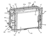
図4、図4aは、我々の同時係属の(以前に発行されていない)出願に開示されている車輪付き手荷物ケース30を示し、手荷物容器31、支持車輪組立体32a(32bは不図示)、操舵車輪組立体33、および格納式ハンドル39を備えている。手荷物容器31は、ベース34、前端部壁35、後端部壁36、側壁37(他の側壁は不図示)によって定義されて手荷物室(コンパートメント)を形成する。蓋38は、ケースが閉じられるとき、コンパートメントの上部に架けられる。容器31と蓋38は、以下に述べられる特殊な構造上の特性を除いて、互いに連携して、典型的な旅行者のスーツケースの一般的な構成と構造を構成する。
4 and 4a show a
この特殊な例において、容器31と蓋38は、互いに連携して一般的な四角形構造を構成する。両要素は、耐久性のある材料で形成される。ケース30は、もちろん、他の形状を持つことができ、他の材料で形成されることができ、そして、どのような寸法の手荷物ケースにも同じように適用できる。全てのケースについて本質的というわけではないが、手荷物容器31と蓋38は、互いに連携して、その高さよりも、長く、幅広いのが、最大の安定性を与えるので好ましい。
In this special example, the
蓋は、これらの技術に熟練した者に知られている種々の方法によって、手荷物ケースに固定され、蓋が閉じられる種々の方法として、ジッパ、ロック、留め金、その他の保持手段などを含むが、これらに限定されるものではない。ケース30は、床、歩道などを転がされるように設計されている一方で、少しの距離だけ動かされるときに、ケースを持って運ぶことができるように、通常の手持ちグリップ(不図示)を備えるのが好ましい。本発明は、他の形式のヒンジ、閉鎖具、ラッチ手段、および、ケースを運ぶための手段を備えた手荷物ケースに同じように適用できる。
Lid, by a variety of methods known to those skilled in these technologies, is fixed to the luggage case, as various methods lid is closed, the zipper, lock, clasp, other including and retaining means However , it is not limited to these. While the
一般にU字形状の格納式ハンドル39は、旅行者が、正常な立った姿勢でケース30を押すのを可能にする。ハンドルは、一対の共面平行アーム40を有しており、それは、使用しないときにハンドルの頂点が蓋38から突き出ないように、また、限られた空間においてケース保管場所と干渉しないように、チャンバ41の中に格納され得る。アームの反対の端は、ケースの移動中に使用者によって掴まれるクロスメンバ42によって、つながっている。ハンドル39は、それぞれのアームがテレスコープ構造になっており、伸ばしたり縮めたりすることができる。使用に際して、旅行者が、伸ばし具合を選ぶことができるように、アームを所定の位置に固定する手段を備えている。
A generally U-shaped
空間をおいて離れて支持車輪組立体32a,32b(不図示)が、手荷物容器31の向かい合った側面領域であって、容器31の後端部壁36の近くに配置され、下方に伸びて支持面に接触している。
Supporting
ケースのベースの支持面からの傾斜は、大股歩行のための空間を提供するように、ハンドルバーを後方に傾ける。ケースの後部面の部分は、大股歩行のための追加の空間を与えるためにオプションで凹んでいる(図参照)。操舵車輪組立体33は、示されるように操舵車輪組立体33が手荷物容器34の底部壁の下に展開している使用状態の位置と、操舵車輪組立体が前方壁35から重大な状況となるほどには突き出ておらずまた限られた空間のケース保管場所と干渉することがないように手荷物容器の中に実質的に納められている非使用状態の位置と、の間でピボット構造的に移動可能である。
The inclination from the support surface of the base of the case tilts the handlebar backward so as to provide a space for large-scale walking. The rear face portion of the case is optionally recessed to provide additional space for the crotch walking (see figure). As shown, the
次に図5乃至図9によって、本発明の第1の好ましい実施形態が述べられる。これは、車輪による移動の複数モードを許すことにより、また操舵車輪組立体を備えるための極めて効率的な手段を提供することによって、図4と図4aに関連して上述した我々の先の車輪付き手荷物ケースの発明の原理に基づき、また改善するものである。 A first preferred embodiment of the present invention will now be described with reference to FIGS. This allows our previous wheel described above in connection with FIGS. 4 and 4a by allowing multiple modes of wheel movement and by providing a highly efficient means for providing a steering wheel assembly. This is based on the principle of the invention of the attached baggage case and is an improvement.
我々の先の車輪付き手荷物ケースと共通に、本発明のケースは、標準のハンドキャリースーツケースのように手で持ち運ぶことができ、同様に、押すトロリー/カートとして押して使うことができる。それは、また、ユーザの高さ位置の横で、ケースの端部壁に装着された一方向性、又は好ましくは多方向性の車輪によって、人間工学性および梃子を最適化するように、真っ直ぐな、または好ましく湾曲した/”屈曲した”格納式のハンドルを用いて引くことができる。車輪移動の第3のモードとして、ケースは、カートの要領で転がされるように、端部壁の回転車輪上で傾ける、すなわち、端部壁よりも主壁によって傾ける、ことができる。改良された手荷物ケースは、従って、移送中の様々な状況に対処するために、車輪移動の複数のモードを有する。この多芸により、ユーザが、移動する状況や地形に最適化にするように、移動に最適のモードを選択できる。 In common with our previous wheeled luggage case, the case of the present invention can be carried by hand like a standard hand carry suitcase and can also be pushed and used as a push trolley / cart. It is also straight so as to optimize ergonomics and levers by a unidirectional, or preferably multi-directional, wheel mounted on the end wall of the case, next to the user's height position. Or preferably with a curved / "bent" retractable handle. As a third mode of wheel movement, the case can be tilted on the rotating wheel of the end wall, i.e. tilted by the main wall rather than the end wall, so that it is rolled in the manner of a cart. The improved baggage case therefore has multiple modes of wheel movement in order to cope with various situations during transfer. With this multi-purpose, the user can select the optimum mode for movement so as to optimize the situation and the terrain to move.
図5乃至図9における第1の実施形態は、非格納式の支持車輪組立体57a,57b付きの手荷物容器56を有する車輪付き手荷物ケース55、格納式操舵車輪組立体58、および格納式ハンドル59を備えている。
The first embodiment in FIGS. 5-9 includes a
手荷物容器56は、ベースまたは底部壁60、前端部壁61、後端部壁62、第1側壁63、および対向側壁64を有し、これらは、全体として手荷物室(コンパートメント)を形成し、コンパートメントの上部に架けられる蓋65によって閉じられる。先の我々の手荷物ケースの設計のように、容器56と蓋65は連携して、以下に述べられる特殊な構造上の特性を除いて、旅行者の典型的なハンドキャリするスーツケースの一般的な構成と構造とを有する。2つの対向する長い広い(主)面、2つの対向する長く/狭い端部壁面、および、2つの短く/狭い端部壁を有し、形状が適切に実質的に四角形であることが望ましい。持ち上げるためのキャリハンドルは、長く狭い面の1つ、および/または短く狭い端部壁の1つに備えることができる。
The
図4の車輪付きケースのように、この車輪付きケース55の好ましい第1の実施形態は、正常に真っ直ぐ立った姿勢で歩くときに、一般的なU字形状の格納式ハンドル59を用いて、旅行者によってトロリーの要領で押すことができる。ハンドル59の平面平行アーム66a,66bの対は、テレスコープの仕方で格納される。対向するアームの上端は、ハンドルバー67として機能する上部クロスメンバによって接続されている。この車輪付きケースの好ましい実施形態において、格納式ハンドル59は、真っ直ぐではなく湾曲したアーム66を有する。さらに、図4のケースの設計とは異なり、好ましい車輪付きケースの実施形態は、ここでは操舵車輪組立体58を構成し、それはアーム66の下部端を繋ぐ低部クロスメンバ68にあるキャスタ輪58を備える。従って、それはケースの端部壁の凹部にしまい込まれるが、操舵可能な車輪組立体58はハンドル59の低部クロスメンバ68にピボット構造的に実装されるのであって、ケースの底部壁60にではない。
A preferred first embodiment of the
さらに、格納式ハンドル59は、図4のケースとは異なり、(それは、変形例として、ハンドルステム/アームを容器に貫通させて、内部に実装できるけれども)ケースの側壁に外部から備えられている。ハンドル59の1つのアーム66aは、ピボット69aによって、ケースの一方の側壁に軸支され、他のアーム66bは、ピボット69bによって、ケースの他方の側壁に軸支されている。従って、格納式ハンドル59は、ケースに相対的にテレスコープ伸長態様で動くことができるだけでなく、ケース回りに回転でき、ケース回りで回転するときに、それは、低部クロスメンバ68に取り付けられた操舵車輪組立体58の位置を変化させ、ケースの端部壁における容器70にしまい込まれた位置から、ケースの下側を隣接して支える使用状態へと、その位置変えを可能とする。ハンドル59および関連する操舵車輪組立体58の使用の段階々々が図7aから図7fに示されている。
Furthermore,
図5、図6から明らかな車輪付きケースの構成のさらなる特徴は、ピボット69a,69b回りのハンドル59の回転運動の広がりを制限するエンドストップの使用にある。ハンドル59および連携する操舵車輪組立体58がしまい込まれた位置にあるとき、ハンドルはハンドルバー67に隣接する第1のエンドストップ72によって、また、その他端は第2のエンドストップ71によって引き留められる。各エンドストップ71,72は、出っ張ったつまみの形を有し、他の2つのつまみ73,74と共に小さな脚の役割もし、ハンドル59の腕が地面に押し付けられるのを防ぐために、ケース側壁を地面から離す。つまみ形状の脚/エンドストップ73は、操舵車輪組立体58が完全使用状態とするため回転されたハンドル59を引き留めるように備えられている。さらなる4つめのつまみ形状の脚/エンドストップの脚74は、ハンドル59を使用できるようにするため、図8、図9を参照して後述されるように、格納または変向して適用される。
A further feature of the wheeled case configuration apparent from FIGS. 5 and 6 is the use of end stops to limit the spread of the rotational movement of the
格納式ハンドル組立体は、それぞれがテレスコープ部を備えたアーム66a,66bを有する。各アーム66a,66bの底部75は、操舵車輪組立体58が実装される低部クロスバー68を有している。底部75は、その”上”端においてケース側壁にそれぞれピボット69a,69bによって実装され、それは、中にアーム66a,66bの中間部76がテレスコープのように摺動して受け止められるチューブ状スリーブの形状を有している。アーム66a,66bの各中間部76は、同様に、チューブ状スリーブに形成され、テレスコープのように摺動して内部に受け止められる上アーム部78を有し、その”上”端にはハンドルバー67を有している。中間部76の”上”端には、さらに、第1のエンドストッパ72に鉤止めするように見えるフック様に形成されたチューブ状ボディ77がある。これらの各アーム66a,66bのフック様チューブ状ボディ77は、中間クロスバー79によって結合され、それらのフック形状は、ケースの底部壁60の端におけるリベート(rebate)80に納まることができるようにクロスバー79を位置決めするために、アーム66a,bから、十分突出している。この中間クロスバー79は、ハンドル組立体59を補強し、加えて、傾けて/立てた状態の車輪モードで使われる場合に、ケースの底部壁60の端部におけるリベート80内に収容されて、ハンドル組立体59が意図せずに回転されないように保つことを助ける。
The retractable handle assembly has
図5と図6に見られるように第1の好ましい実施形態の車輪付き手荷物ケースのさらなる特徴として、それぞれケースの一端および一側壁における従前のハンドキャリ用のハンドル81,82を備えている。また、小さなキャスタ輪83が、ハンドキャリ用のハンドル81を有するケースの端部壁とは反対側のケース端部壁に備えられており、ハンドルは車輪移動によるトロリーモードとして使われるのと同じように、車輪移動のこのモードのための押し/引き用のハンドルバー67と同じくユーザが適切に掴み、ケースが旅行者の横で立てて引かれる。ハンドルバー67がしまい込まれる位置に隣接する、手荷物ケース容器の端部壁における凹部または除去部90は、それがしまい込まれているときに、ハンドルバーを掴もうとするときに都合がよい。
As seen in FIGS. 5 and 6, as a further feature of the wheeled baggage case of the first preferred embodiment, there are
図7a乃至図7fにおいては、これらは車輪移動の2つのモードの間における変化を示す。これらの最初の図において、ケースはユーザの横で立てて移動するモードにある。ハンドル59は、非使用の/しまい込まれた回転位置にあり、図5、図6と共通であるが、ハンドルバー67の引出によって、ハンドルバーの上部78が中間部76から出て部分的にテレスコープ様に伸長されていおり、その位置に適切にロックされている。この部分的テレスコープ伸長位置は、ケースの高さに対してユーザから届きやすいように選択される。
In Figures 7a to 7f, these show the change between the two modes of wheel movement. In these first figures, the case is in a mode of moving on its side. The
図7bにおいて、ハンドル59は、さらにテレスコープ伸長され、各アーム66a,66bの中間部76が底部75からさらに引き出される。この動作は、有効にロックを外して中間クロスバー79をケース端部壁のリベート80内から持ち上げ、それが端部壁を越えるように十分持ち上げ、ハンドル59がピボット69a,69b回りに傾けられる。このとき、操舵車輪組立体58は、同時に、ケースのベース壁60におけるその凹部70から持ち上げられる。図7dにおいて、ハンドル59は、ピボット69a,69bの回りにさらに傾けられ、その過程で、邪魔に成らないように脚/ストッパ74を押し除ける。
In FIG. 7 b, the
ハンドル59をさらに傾斜させる極限において、それは、操舵車輪組立体58の使用状態に対応する終極の落ち着き位置に至り、そこでは、低部クロスバー68がケースのベース壁60に押し付けられ、アーム66a,66bの中間部76は第3のエンドストップ73を押しつける。低部クロスバー68は、水平ロックバーとして作用し、ケースに対してハンドル59のさらなる回転を阻止し、ケースの重さによって位置が保持され、使用状態にある操舵車輪組立体をロックするためのロック機構の必要性を回避し、ピボットにかかる応力を減らす助けをするように比較的大きな面積に亘ってケースの重さを分布させる。
In the limit of further tilting the
第3のエンドストップ73は、ハンドル59の回転使用において、または手荷物の重量からの、過大の力が操舵車輪組立体58、およびピボット69a,69bにかかるのを阻止する。
The
図8、図9を参照のごとく、ストッパ/脚74は、ハンドル59が上げられるときに、ハンドルアームの中間部76によって邪魔にならないよう押し戻されるように、ケースに軸支して実装されている。図9を見て分かるように、ストッパ/脚74は、直立したレバーピン74aを有し、それは、ハンドル59と操舵車輪組立体58を非使用位置へと戻すために、アームがそのしまい込み状態に戻されるときに、アーム中間部76を受け止める。従って、中間部76は、そのしまい込み位置に戻る際にレバーピン74aを押し、それによってストッパ/脚74を、その展開された位置に戻す。
As shown in FIGS. 8 and 9, the stopper /
次に、図10a乃至図10dに示される本発明の第2の好ましい実施形態につき、ここにおける車輪付き手荷物ケースは、それぞれがハンドル59の低部に実装されてケースの各側に各1つとされる操舵車輪58a,58bの対を備えた操舵車輪組立体を有する。この第2の好ましい実施形態は、中間または低クロスメンバを有さず、ハンドル59のケースの側壁への軸支実装は、関節で接合されている。各アーム76a’,76b’は、それぞれのケース側壁におけるそれぞれのチャネル84a,84bに沿ってスライドするように強制されるピボット69a’,69b’によって、ケースのそれぞれの側壁に実装されている。ハンドル69のアーム76a’,76b’は、真っ直ぐで、曲がりがなく、しかし、実質的に第1の実施形態におけるアーム76a,76bと同様の方法でテレスコープ伸長し、ハンドル59と操舵車輪組立体58a,58bの使用時動作は、第1の実施形態のそれと同様であり、ハンドルバー67は、車輪58a,58bがしまい込まれた状態(図10a)にあるとき、初期にケースの底壁に対して幾分下向きに傾斜しており、しかし、反転されて上向きに向かされ手荷物ケースからユーザの方に傾斜される(図10d)。この第2の実施形態は、第1のエンドストップ72’を有し、それに対して、しまい込み状態においてハンドルアーム76a’,76b’が休止し、さらなるエンドストップ73’を有し、それに対して、操舵車輪が使用状態においてアーム76a’,76b’が休止する。これらの2つに位置の間において、さらなる移動止めつめ85が移動止めつめ、および、ハンドル59が回る第2のピボットとして機能し、第1のピボット69a’,69b’がそれぞれのチャネル84a,84bをすべり下がるように強制されるときに、その回りを回る。この移動止めつめ85は、また、第1のピボット69a’,69b’がそれらの対応するチャネル84a,84bの端に達したときに、操舵車輪組立体58a,58bの使用状態位置のためのエンドストップとして機能する。
Next, according to the second preferred embodiment of the present invention shown in FIGS. 10a to 10d, the wheeled luggage cases here are each mounted on the lower portion of the
図11、図12を参照すると、これらは、ハンドル59、および関連する操舵車輪組立体58a,58bの2つの択一的な端の状態を示す。図11において、ハンドル59はケースの側壁のそばにしまい込まれた操舵車輪組立体58a,58bを伴って非使用状態にあり、この位置において、ユーザは、或る角度にケースを傾斜させて、その固定された車輪57a,57bを転がして、ハンドル67によってケースを快適に引くことができる。図12において、操舵車輪が使用される配置で、ユーザはケースをトロリーのように引いたり運転したりできる。これらの図から理解できるように、これおよび本発明の他の全ての実施形態は、特に好ましくは、操舵車輪組立体が使用されるとき、ベース壁を地面に対して傾斜して地面に対して鋭角を成し、支持車輪から上方に傾けたベース壁を、保持するように配置される。これは、ユーザの快適性と操縦性を大きく改善する。
Referring to FIGS. 11 and 12, these show two alternative end states of the
図10a乃至図12から分かるように、ハンドル59をケースに対して動かすことによってハンドルを使用する単純な動作は、操舵車輪組立体を同時に使用状態にさせるばかりでなく、それを1つの車輪移動モードから他の1つの車輪移動モードへと動かし、それらの各々は、ハンドル59を、ケースに対する便利な角度と位置にしてユーザに提供する。図11の位置において、ユーザは優れた歩行空間と、納得できる快適なハンドルバー67の高さを確保し、図12の位置において、ユーザはトロリー移動モードにおいて用いられるケースについて実質的に最適のハンドル構成を有する。
As can be seen from FIGS. 10a-12, the simple operation of using the handle by moving the
図13a乃至図13cに示される、本発明の次の実施形態は、静的ピボット91によってケースの側壁に直接軸支して取り付けられたハンドル59のハンドルステムを有し、操舵車輪組立体58を使用位置に展開するための移動の制限された角度だけのハンドル回転を有する。この実施形態は、一般に真っ直ぐで、湾曲しないハンドルステム/アームを有し、その最も低い端はアームの主たる長さ部に対して或る角度を有する。この構成は、特に設計と操作において、上述の先行する実施形態に比べて単純である。或る用途において、操舵車輪組立体を安全に使用状態に保持するためにラッチ構造が備えられる。ハンドルをしまい込み位置に保持するためのラッチまたはロックは、また、特に好ましくは、縦にして傾けて車輪移動するモードにおいて操作を安全にするために備えられ、車輪移動における両モードに対して、ハンドル59/ハンドルバー67’の使用を容易にする。しまい込まれたハンドルバー67’を維持するためのリベート80は、図13の実施形態において与えられ、第1の実施形態におけるリベート80と同様に機能する。ハンドルバー67’のしまい込み位置に隣接する、手荷物ケース容器の端部壁における凹部または除去部90は、それがしまい込まれたときにハンドルバー67’を掴むのに適合している。
The next embodiment of the present invention, shown in FIGS. 13 a-13 c, has a handle stem of a
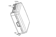
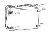
図14においてケースは、剛体による/押すことのできるハンドルステムに代えて、柔軟なストラップ101を備えるハンドル100を有する。これは重さが軽く、コンパクトな形に格納でき、ユーザおよび異なる使用モードに適合する様に、数々の任意の引き延ばし選択長に適切に固定できる。図15は、さらなるケースを示し、ここにクロスメンバ103によって連結された1対の反転可能操舵車輪102a,bを有する。ここで、ハンドル100は、ケースの底部壁により近く、従って、縦にして傾けた移動モードでの使用がより容易である。実際、ストラップ101は、図14の構成とは違って、蓋から伸びていなく、従って、縦にして傾けたモードにおけるケースに対する、より良い支持を提供できる。
In FIG. 14, the case has a
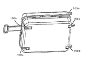
図16a乃至図16dを参照すると、ケースはそこでとりわけ、剛体のテレスコープ構造ハンドル104、およびトロリー移動、または端部壁のエッジ回りに回転して縦にして移動する際にケースを支持できる、1対の傾斜可能車輪105c,105dを備えている。さらなる特徴は、ケースを引くために使うことができるクリップ108’を有するストラップ107’であり、例えば手を使わずにケースを引くことができるように、ユーザのベルトにクリップ止めできる。図16a、図16dは、ストラップ107’のための2つの代替有用取付具を示す。
Referring to FIGS. 16a to 16d, the case can support the case, among other things, as the rigid
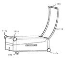
図17a乃至図17cは、ケースの変形例を示し、それは、湾曲したテレスコープ的に伸長できるハンドル112,113、操舵車輪組立体109、支持車輪110a、また、ケースが縦にして傾けて引かれるときに使用できる特別の2つの車輪111a,111bの組を有する。
Figures 17a to 17c show variations of the case, which are curved telescopically
図18、図18bは、本発明のケースの積み重ね容易性を示し、それらがどのように、一緒にクランプされるかを示し、1つのケースにおけるラッチクラスプ114aが、接して積まれたケースにおける協同して結合する特徴物(例えば、バーまたは肩)114bに架けられる。図19a乃至図19cおよび図20a、図20bにおいて、ケースの収まりは、ケースの蓋における車輪収容凹部115a,115bによって容易とされる。
18 and 18b show the ease of stacking of the cases of the present invention, how they are clamped together, and the cooperation in the case where the
操舵車輪組立体が複数の操舵車輪を備え、単純に1車輪ではないことに留意すべきである。 It should be noted that the steering wheel assembly comprises a plurality of steering wheels and is not simply one wheel.
本発明は、新規の設計を提供し、それは、特により大きなサイズの旅行スーツケースとして有用であるが、多様な範囲のサイズ、形状、および型のケースとして用いることができる。それは最小の努力でポータブルであり、使用するには、高度に扱いやすく安定で便利である。スーツケースは、軽い重量、堅固、格納可能な押しハンドルを持つトロリーまたはトレラー型の設計、および格納可能な車輪を有し、先行技術に対して数々の重要な優位点を有する。 The present invention provides a novel design, which is particularly useful as a larger size travel suitcase, but can be used as a range of sizes, shapes, and types of cases. It is portable with minimal effort and is highly manageable, stable and convenient to use. The suitcase has a light weight, a solid, trolley or trailer design with retractable push handles, and retractable wheels, and has a number of important advantages over the prior art.
トロリー/トレラー移動モードにおける広いベース部と低い重心の設計は、種々の従来のスーツケースの設計と比べて、本来、より安定である。傾斜させて車輪の上に載せてケースを綱で引くのと異なり(例えば、米国特許No.5116289号参照)、この設計は、移動時において自己安定かつ自己支持のものである。このケースは、高度に操作性が良く、格納式押しハンドルは、ハンドルと車輪とが格納されたときに、スーツケースを縦にして傾けて車輪で転がされるようにできる。格納式ハンドルは、現代の軽量で頑丈なアルミ合金を用いて、様々な設計オプションに基づいて容易に製造される。 The wide base and low center of gravity design in the trolley / trailer travel mode is inherently more stable than various conventional suitcase designs. Unlike tilting and placing the case on a wheel and pulling the case (see, for example, US Pat. No. 5,116,289), this design is self-stable and self-supporting when moving. This case has a high degree of operability, and the retractable push handle can be rotated by the wheel by tilting the suitcase vertically when the handle and the wheel are stored. The retractable handle is easily manufactured based on various design options using modern lightweight and sturdy aluminum alloys.
格納式の車輪は、車輪が必要なときのみ使われるようにでき、手荷物の輸送の間に露出した車輪の損傷ということを避けることができる。ケースは、”カート”が傾けられたときのみ使用状態となる2つの小さい軽量のローラブレード様の後部車輪/支持車輪を備えることができる。前部における操舵車輪組立体は、ケースを適切に傾けて、これらの後部車輪/支持車輪を使用するようにし、ケースがトロリーまたはトレラーとして機能するようにできる。この設計は、ケースそのものの体積と重量を最小化し、ケースの使用に際して実用的で便利なものとする。押しトロリー型のスーツケース設計は、大きくて重い荷物を動かすために、人間工学的に適合している。さらに、重い荷物は引くよりも押す方がより簡単である。この押しトロリー型スーツケースの設計は、重いスーツケースの荷物を運ぶとき、より少ない努力で、より詳細な制御を可能とする。さらに、このトロリー型スーツケースの設計は、90゜コーナからバックしたり、段差からバックで降りたりするときのように、引っぱる目的にも対応できる。押しトロリー型のスーツケース設計は、押しトロリーそのものとして用いることができる。他の手荷物が、その上に積み重ねられ、空港や鉄道駅の押しトロリーの用途として荷を運ぶことができる。ケースは現代の、タフで軽く丈夫なプラスチックを用いて実現でき、または、例えば、アルミニウム/他の金属/合金の骨組みで強化されたキャンバス地や他の強う材料を用いることができる。 Retractable wheels can be used only when the wheels are needed, avoiding damage to exposed wheels during baggage transport. The case can include two small lightweight roller blade-like rear / support wheels that are in use only when the “cart” is tilted. The steering wheel assembly at the front can tilt the case appropriately to use these rear / support wheels, allowing the case to function as a trolley or trailer. This design minimizes the volume and weight of the case itself, making it practical and convenient to use the case. The push trolley type suitcase design is ergonomically adapted to move large and heavy loads. In addition, it is easier to push heavy loads than to pull them. This push trolley type suitcase design allows for more detailed control with less effort when carrying heavy suitcase luggage. Furthermore, the design of this trolley-type suitcase can also be used for pulling purposes, such as when backing from a 90 ° corner or descending from a step. A push trolley type suitcase design can be used as the push trolley itself. Other baggage can be stacked on top of it and carried as a push trolley for airports and railway stations. The case can be realized using modern, tough, light and durable plastics, or can be made of canvas or other tough materials reinforced with an aluminum / other metal / alloy framework, for example.
スーツケースのベース部は、格納式車輪が使用されるとき傾斜した状態となり、このことは、後輪が使用状態となるのを助けると共に、重心を後輪の方にシフトさせ、三輪車の安定性、および、前部の多方向性車輪の操作性を改善する。また、ハンドルバーを後方に傾斜させるので、ケースを押しながら歩くときの足運びのための空間を確保でき、これはさらに、トロリーとして用いたときに上に重ねて乗せた手荷物を保持可能とする。 The suitcase base is tilted when retractable wheels are used, which helps the rear wheels to be in use and shifts the center of gravity towards the rear wheels, making the tricycle stable And improving the operability of the front multidirectional wheel. In addition, because the handlebar is tilted backwards, it is possible to secure a space for walking when walking while pushing the case, and this can also hold baggage stacked on top when used as a trolley .
図示され、また上述されたように、格納式の操舵車輪組立体は、手荷物ケースに用いられ、ここに、操舵車輪組立体と支持車輪とは、実質的に同等サイズである。 As shown and described above, the retractable steering wheel assembly is used in a luggage case, where the steering wheel assembly and the support wheel are substantially the same size.
手荷物スーツケースの転がり移動の”押しトロリー”モードは、転がり手荷物スーツケースの従来モードに比べて幾つかの理由により有利である。これらは、(a)車輪で手荷物を移動させるための改善された人間工学性、(b)荷物を押す際に自分自身の重さを用いて助けるので、荷物を引くよりも同じ荷物を押すのにより少ない努力で済む、(c)低い重心と広いベースが最大の安定性を与える、(d)車輪構成、特に三輪車構成が最適な操縦性を提供する、(e)車輪システムが自己支持でありユーザにはケースのバランスを保つ努力が要求されない、(f)ケースをカートとして用いることができ、その上部に手荷物の他の物が積まれて、運搬される、(g)上記のように、車輪付きケースは、適切な付属品(例えば、座席)や安全装置(例えば、ブレーキ)を備えることにより、手押し乳母車または車椅子きの機能に容易に適用できる。 The “push trolley” mode of rolling movement of baggage suitcases is advantageous for several reasons compared to the conventional mode of rolling baggage suitcases. These are: (a) improved ergonomics for moving baggage on wheels, (b) using the weight of oneself to assist in pushing the baggage, so pushing the same baggage rather than pulling the baggage (C) Low center of gravity and wide base provide maximum stability, (d) Wheel configuration, especially tricycle configuration, provides optimal maneuverability, (e) Wheel system is self-supporting The user is not required to make an effort to balance the case, (f) the case can be used as a cart, and other items of baggage can be loaded and carried on top of it (g) as described above, The wheeled case can be easily applied to the function of a hand-held baby carriage or wheelchair by providing appropriate accessories (for example, a seat) and safety devices (for example, a brake).
押しトロリーの機能に加えて、押しトロリー型のスーツケースは、適切な付属品や安全装置を設けることにより、赤ちゃんやよちよち歩きの小児のための押し椅子や乳母車に転換できる。代替としてまたは追加として、ケースは通行する人が乗る動力車両/自動車として適用できる。 In addition to push trolley functions, push trolley-type suitcases can be converted into push chairs and prams for babies and toddlers by providing appropriate accessories and safety devices. As an alternative or in addition, the case can be applied as a powered vehicle / automobile with a passerby.
操舵車輪組立体をハンドルを介して使用する手段の提供は、トロリーモード機能を使用状態とするワンステップの使用操作を効果的に可能とし、この押しトロリー機能を使用化、非使用化とする容易さと便利さとを最適化する。ケースは、車輪移動の異なるモードの間で、容易に転換できる。 Providing means for using the steering wheel assembly via the steering wheel effectively enables one-step use operation to use the trolley mode function, and makes it easy to use and disable this push trolley function. Optimize for convenience and convenience. The case can be easily switched between different modes of wheel movement.
本発明の新しい二重機能転換可能トロリー構成は、自己支持であり、低い重心と広いベースを有して安定であり、ぐらつくことなく操作性が良く、人間工学的であり、荷物を引くよりも(体重を加えて使用でき)押し易く、ケースの上に他の手荷物を積み上げ易く(各ケースにおいて最大表面積が可能、低い重心と広いベースによる初期の安定性)そして大変多芸である。それは、我々の先の”トロリー”発明がツーステップ使用であるのに比べて、ワンステップ使用であり、それぞれが、事実上何らの追加の”機構”/重量を伴なわずに両方の機能の利点を有する二重の機能(カートとトロリー)を備えている。 The new dual function convertible trolley configuration of the present invention is self-supporting, has a low center of gravity and wide base, is stable, is easy to operate without wobbling, ergonomic, and more than pulling luggage Easy to push (can be used with added weight), easy to stack other baggage on the case (maximum surface area possible in each case, initial stability with low center of gravity and wide base) and very versatile. It is a one-step use compared to our previous “trolley” invention being a two-step use, each of both functions without virtually any additional “mechanism” / weight. Has dual function (cart and trolley) with advantages.
トレラーとしての構成においては、その構成は、テレスコープ様のハンドルやハウジングを持たないことにより、一般的にトロリー配置よりもより以上に軽く、”カート”や”スピナケース”よりも軽い。その構成は、カートとスピナケースに比べて、移動に際してより努力を要さず、カートとスピナケースに比べて、より人間工学的である。ケースは、自己支持であり、低い重心と広いベースを有して安定であり、ぐらつくことなく操作可能であり、ケースの上に他の手荷物を積み上げ易く、コンピュータ/ビジネス/書類ケースなどを含む小さな(可能性として中間の)サイズのケースのための、ハンドフリー機能の能力を広げる。さらに述べると、荒い表面(例えば道路)を移動する際に、カート、スピナ、またはトロリーケースに比べて、非常に少ない振動しか手に伝わらない。ケースは、また、トロリー配置に比べて、より易く製造を実行でき、カートやスピナケースに比べても、より易く製造できる。ケースは、カートやスピナケースに比べて、潜在能力として(上りの坂道で)より努力を要さず、または、(下りの坂道で)制御がより困難ではない。 In a trailer configuration, the configuration is generally lighter than a trolley arrangement and lighter than a “cart” or “spinner case” by not having a telescope-like handle or housing. The configuration requires less effort to move than the cart and spinner case, and is more ergonomic than the cart and spinner case. The case is self-supporting, has a low center of gravity and a wide base, is stable, can be operated without wobbling, is easy to stack other baggage on the case, is small including computer / business / document cases, etc. Expand the capabilities of the hands-free function for (possibly intermediate) size cases. More specifically, when moving on rough surfaces (eg roads), very little vibration is handed compared to carts, spinners or trolley cases. The case can also be manufactured more easily than a trolley arrangement, and can be manufactured more easily than a cart or spinner case. The case requires less effort (on the uphill) as a potential or less difficult to control (on the downhill) than the cart or spinner case.
本発明のケースのトロリーまたはトレラー構成によって提供されるさらなる機能は、その移動モードにおける段差を登る能力である。実際、ケースは、さらにスキッドまたはローラをその底部壁に持たせ、その壁が地面に近接することによって、かなり容易に、ぐらつく危険性なく滑らせたり、あるいは、操縦して、段差を登りまたは下ることができる。 A further function provided by the trolley or trailer configuration of the case of the present invention is the ability to climb steps in its travel mode. In fact, the case also has a skid or roller on its bottom wall, which can be slid or maneuvered to climb or descend a step fairly easily, with its wall close to the ground be able to.
Claims (18)
前記底部壁の一方の端に配置された複数の非格納式支持車輪と、
使用時に前記支持車輪から離されて前記底部壁に配置され、少なくとも1つの車輪を有し、前記手荷物容器の底部壁の下に展開している使用状態の位置と格納された非使用状態の位置との間で移動可能な格納式操舵車輪組立体と、
前記手荷物容器の一方の端に配置され、操舵し、押し、および/または、牽引するためのハンドルと、を備え、
前記手荷物ケースは、前記格納式操舵車輪組立体と前記非格納式支持車輪とを接地用として用いて前記底部壁が地面に面し、前記ケースが格納式操舵車輪組立体の先導のもとで前記ハンドルによって押されて進む第1の車輪移動モード、または、代替の接地用車輪配置を用いて1つの端部壁が地面に面している第2の車輪移動モードについて選択的に使用できる構成とされている車輪付き手荷物ケース。A wheeled baggage case having a baggage container, the container having two opposite main walls and a plurality of end walls constituting a baggage compartment, wherein one main wall of the container is the baggage case. The bottom wall facing the ground when moving in wheel mode, the baggage case is further
A plurality of non-retractable support wheels disposed at one end of the bottom wall;
A position in use and located at the bottom wall, spaced apart from the support wheel in use, having at least one wheel and deployed below the bottom wall of the baggage container and a stored non-use position A retractable steering wheel assembly movable between,
A handle disposed at one end of the baggage container for steering, pushing and / or towing,
The baggage case uses the retractable steering wheel assembly and the non-retractable support wheel for grounding, the bottom wall faces the ground, and the case is led by the retractable steering wheel assembly. first wheel movement mode traveling pushed by said handle, or, selectively used for the second wheel movement mode in which one of the end walls with ground vehicles Wahai location alternative is facing the ground A wheeled baggage case that can be configured.
Applications Claiming Priority (3)
| Application Number | Priority Date | Filing Date | Title |
|---|---|---|---|
| GBGB0517720.9A GB0517720D0 (en) | 2005-08-31 | 2005-08-31 | Improved luggage |
| GB0517720.9 | 2005-08-31 | ||
| PCT/GB2006/003226 WO2007026154A2 (en) | 2005-08-31 | 2006-08-31 | Improved luggage |
Publications (2)
| Publication Number | Publication Date |
|---|---|
| JP2009505763A JP2009505763A (en) | 2009-02-12 |
| JP4897812B2 true JP4897812B2 (en) | 2012-03-14 |
Family
ID=35198659
Family Applications (1)
| Application Number | Title | Priority Date | Filing Date |
|---|---|---|---|
| JP2008528576A Expired - Fee Related JP4897812B2 (en) | 2005-08-31 | 2006-08-31 | Improved baggage case |
Country Status (13)
| Country | Link |
|---|---|
| US (2) | US8490765B2 (en) |
| EP (4) | EP1947975A2 (en) |
| JP (1) | JP4897812B2 (en) |
| KR (1) | KR101393966B1 (en) |
| CN (2) | CN101262792B (en) |
| AU (1) | AU2006286312B2 (en) |
| BR (1) | BRPI0617051A2 (en) |
| CA (1) | CA2620573C (en) |
| GB (2) | GB0517720D0 (en) |
| RU (2) | RU2427301C1 (en) |
| SG (3) | SG165332A1 (en) |
| WO (1) | WO2007026154A2 (en) |
| ZA (1) | ZA200802537B (en) |
Families Citing this family (55)
| Publication number | Priority date | Publication date | Assignee | Title |
|---|---|---|---|---|
| GB0517720D0 (en) | 2005-08-31 | 2005-10-05 | Lee Paul T H | Improved luggage |
| JP4431151B2 (en) * | 2007-01-11 | 2010-03-10 | 享憲 神谷 | Carry Bag |
| US20080308369A1 (en) * | 2007-06-15 | 2008-12-18 | Louis Robert D | Luggage transport system |
| KR100914262B1 (en) * | 2008-12-01 | 2009-08-27 | 황희 | Latch-cum-loop for bag and changeable handbag using same |
| FR2948265B1 (en) * | 2009-07-23 | 2012-12-28 | Daniel Naud | TOWABLE HANDBAG COMPRISING A SUPPORT SYSTEM |
| GB201017526D0 (en) | 2010-10-18 | 2010-12-01 | Ultimate Products Ltd | Luggage |
| US20120228074A1 (en) * | 2011-03-08 | 2012-09-13 | Scott Osler | Travel Master |
| US9126323B2 (en) | 2011-08-22 | 2015-09-08 | The Procter & Gamble Company | Device for treating a target surface and having an ergonomically pivoting handle |
| US8757642B2 (en) * | 2012-05-22 | 2014-06-24 | Retract Enterprises Inc | Retractable wheel assembly |
| CN202680868U (en) * | 2012-07-04 | 2013-01-23 | 上海冶成国际贸易有限公司 | Improved luggage box |
| ES2632059T3 (en) | 2012-07-09 | 2017-09-08 | Royalty Bugaboo Gmbh | A luggage item, a luggage item system, a luggage item adapter |
| US9066565B2 (en) | 2012-11-09 | 2015-06-30 | Samsonite IP Holdings S.ar.l. | Luggage with shells having varied depths |
| US9060577B2 (en) | 2012-11-09 | 2015-06-23 | Samsonite Ip Holdings S.A R.L. | Luggage with shells having varied depths |
| SG11201504921VA (en) * | 2012-12-28 | 2015-07-30 | Ryon Brown | A mobile cart convertible among a plurality of operational modes |
| USD734948S1 (en) | 2013-03-15 | 2015-07-28 | Samsonite Ip Holdings S.A R.L. | Luggage |
| CN203511916U (en) * | 2013-04-01 | 2014-04-02 | 王建民 | Portable and foldable draw-bar box type electric tricycle with function of folding chair |
| BR202013016333U2 (en) * | 2013-06-25 | 2015-11-24 | Nicole Ignácio De Jesus | layout introduced in case with integrated transport device |
| US9254857B2 (en) | 2013-08-30 | 2016-02-09 | David M. Fiebelkorn | Child seat carriage |
| EP3281548B1 (en) | 2013-10-03 | 2019-03-27 | Royalty Bugaboo GmbH | A frame for carrying a luggage item |
| MX2016005503A (en) | 2013-10-28 | 2016-10-13 | Travel-Light Ltd | Wheeled luggage case. |
| EP2904923A1 (en) * | 2014-02-11 | 2015-08-12 | RIMOWA GmbH | Piece of luggage |
| US20150310842A1 (en) * | 2014-04-28 | 2015-10-29 | Gig Armor LLC | System for transporting stringed instruments and assiting performers |
| US9351550B2 (en) | 2014-05-01 | 2016-05-31 | Retrac Enterprises Inc | Wheel deployment apparatus |
| KR20150129547A (en) * | 2014-05-12 | 2015-11-20 | 농업회사법인 주식회사 홀인원 | Movable storage apparatus |
| US10617186B2 (en) * | 2014-08-04 | 2020-04-14 | Samsonite Ip Holdings S.A.R.L. | Spinner wheel assembly for a luggage article |
| GB2530493A (en) * | 2014-09-19 | 2016-03-30 | Sunrise Properties Wolverhampton Ltd | A luggage system and components therefor |
| JP6071968B2 (en) * | 2014-09-26 | 2017-02-01 | 株式会社サンカ | Towed storage box |
| CN104287424B (en) * | 2014-10-09 | 2016-08-17 | 平湖市四通箱包有限公司 | A kind of type load school bag |
| JP2016112172A (en) * | 2014-12-15 | 2016-06-23 | 偉浤 頼 | Hard type suitcase constitution |
| WO2016141091A1 (en) * | 2015-03-02 | 2016-09-09 | Kevin O'donnell | Motorized luggage |
| KR101761281B1 (en) | 2015-06-26 | 2017-07-25 | 김태현 | Travel suit case assembly provided with module type |
| CN104997263A (en) * | 2015-07-29 | 2015-10-28 | 胡世棉 | Storage box |
| US20170049202A1 (en) * | 2015-08-21 | 2017-02-23 | Edinaldo Nascimento | Automatic Following Luggage System |
| US9872547B2 (en) | 2015-11-25 | 2018-01-23 | Milwaukee Electric Tool Corporation | Handle assembly for a case |
| FR3046033B1 (en) * | 2015-12-24 | 2018-01-12 | Louis Vuitton Malletier | ROLLING LUGGAGE COMPRISING A RETRACTABLE ROD |
| DE102016209988A1 (en) | 2016-06-07 | 2017-12-07 | Heraeus Medical Gmbh | Paste-like two-component polymethyl methacrylate bone cement |
| US9861170B1 (en) | 2016-06-21 | 2018-01-09 | Robert M. Hamaty | Rolling suitcase that converts to a luggage cart |
| US11253034B2 (en) | 2016-07-11 | 2022-02-22 | Alex Malavazos | Survivor package |
| US10272934B2 (en) * | 2016-07-18 | 2019-04-30 | Ice Rover, Inc. | Multi-terrain multi-purpose insulated container |
| USD816423S1 (en) | 2016-07-18 | 2018-05-01 | Ice Rover, Inc. | Combination container and wagon |
| USD815919S1 (en) | 2016-07-18 | 2018-04-24 | Ice Rover, Inc. | Container |
| ES2938664T3 (en) | 2016-10-18 | 2023-04-13 | Travel Glider IP Pty Ltd as Trustee for Travel Glider IP Unit Trust | Combination luggage and child carrier |
| US10681969B2 (en) | 2016-12-24 | 2020-06-16 | 24-7 International LLC | Luggage cases |
| US9867437B1 (en) * | 2017-02-26 | 2018-01-16 | Donald Dohmann | Luggage system |
| USD881673S1 (en) | 2017-06-16 | 2020-04-21 | Ice Rover, Inc. | Handle |
| CN107114884B (en) * | 2017-06-19 | 2022-07-08 | 山东交通学院 | All-directional movement draw-bar box with terrain adaptability |
| CN207836995U (en) * | 2017-12-12 | 2018-09-11 | 唐昌金 | A kind of ultra-thin folding pull rod luggage case |
| US10568400B2 (en) * | 2018-03-29 | 2020-02-25 | All Bond LTD | Rolling luggage article |
| CN108669740A (en) * | 2018-08-06 | 2018-10-19 | 娄肃萍 | A kind of multi-function suitcase |
| KR200490209Y1 (en) * | 2018-10-16 | 2019-10-11 | 황석진 | Travel carrier |
| TWI725363B (en) * | 2018-12-11 | 2021-04-21 | 緯創資通股份有限公司 | Moving mechanism, mobile carrier and luggage |
| AU2020245231A1 (en) * | 2019-03-22 | 2021-11-18 | Netta Dor SHALGI | Split handle, narrow rolling bag |
| RU197503U1 (en) * | 2019-09-25 | 2020-05-12 | Дмитрий Викторович Любушкин | Cover with push handle |
| US11332263B2 (en) * | 2020-03-24 | 2022-05-17 | The Boeing Company | Trolley system and method for transferring cargo in relation to a cargo compartment of a vehicle |
| IT202000015601A1 (en) * | 2020-06-29 | 2021-12-29 | Alessandro VIVIANI | IMPROVED MODULAR SUITCASE |
Citations (7)
| Publication number | Priority date | Publication date | Assignee | Title |
|---|---|---|---|---|
| US3982613A (en) * | 1975-08-07 | 1976-09-28 | Leeds Travelwear, A Division Of Rapid-American Corporation | Retractable pull strap on wheeled luggage |
| JPS60119903A (en) * | 1983-11-17 | 1985-06-27 | エリツヒ エイ.カーギ | Portable container convertible to hand push wheel and trunk |
| US4913252A (en) * | 1988-11-21 | 1990-04-03 | Bartley B Dean | Motorized luggage |
| JPH0379288U (en) * | 1989-11-19 | 1991-08-13 | ||
| US5313817A (en) * | 1993-05-07 | 1994-05-24 | Meinders Larry L | Wheelable, storable cooler |
| JP2003521262A (en) * | 1998-01-09 | 2003-07-15 | アウトリッガー,インコーポレイテッド | Towable luggage equipment |
| US20040026882A1 (en) * | 2001-04-20 | 2004-02-12 | Deborah Brown | Convertible luggage device |
Family Cites Families (49)
| Publication number | Priority date | Publication date | Assignee | Title |
|---|---|---|---|---|
| US2002836A (en) | 1933-12-04 | 1935-05-28 | Anastasio Petrocelli | Baggage carrier |
| FR968949A (en) | 1948-07-03 | 1950-12-08 | Rolling suitcase | |
| US3178197A (en) * | 1963-03-25 | 1965-04-13 | Boatner Carolyn | Roll along luggage |
| US4228877A (en) | 1978-12-26 | 1980-10-21 | Cothary Walter G | Wheeled suitcase with extendable handle means |
| US4273222A (en) * | 1979-08-22 | 1981-06-16 | K. A. I. Cassimally | Combined portable case and luggage trolley |
| US4261447A (en) | 1980-01-28 | 1981-04-14 | Arias Antonio M | Suitcase cart |
| US4460188A (en) * | 1982-04-15 | 1984-07-17 | Maloof John J | Cart with seat and storage compartment |
| GB2124589A (en) | 1982-08-05 | 1984-02-22 | Chih Chang Chiang | Luggage having rollers |
| DE8300286U1 (en) * | 1983-01-07 | 1983-09-01 | Sudhaus Schloss- Und Beschlagtechnik Gmbh & Co, 5860 Iserlohn | HANDLE |
| FR2598897B1 (en) | 1986-05-23 | 1990-12-28 | Chomard Bernard | LUGGAGE CONVERTIBLE INTO TROLLEY |
| US4717168A (en) | 1986-09-10 | 1988-01-05 | Moon Sr James R | Utility cart |
| US4890705A (en) | 1988-06-10 | 1990-01-02 | Pineda Jose J | Portable file with retracting handle |
| FR2641951B1 (en) | 1989-01-20 | 1991-04-05 | Delsey Soc | RIGID OR SEMI-RIGID CASE IN PLASTIC MATERIAL |
| US5114164A (en) * | 1989-04-13 | 1992-05-19 | Bothwell Peter W | Case |
| JPH0379288A (en) * | 1989-08-23 | 1991-04-04 | Seiko Instr Inc | Oiling device |
| US5048649A (en) | 1990-03-02 | 1991-09-17 | American Tourister, Inc. | Luggage with pull handle |
| GB2245543B (en) | 1990-07-04 | 1994-08-24 | David John Tutcher | Wheeled suitcase |
| US5215318A (en) * | 1990-07-25 | 1993-06-01 | Capraro Anthony L | Body trailer |
| US5116289A (en) | 1991-03-29 | 1992-05-26 | Porter Case, Inc. | Carry-on case having wheels and an extendable handle |
| GB2264481B (en) | 1992-02-26 | 1996-06-19 | Samsonite Corp | Luggage case |
| US5154265A (en) * | 1992-03-17 | 1992-10-13 | Stephen G. Capistrant | Retractable wheel assembly |
| US5249438A (en) | 1992-08-20 | 1993-10-05 | Systemwide Product | Mobile cooler with retractable wheels and handles |
| US5407039A (en) * | 1993-06-04 | 1995-04-18 | Alper; Brad | Wheeled luggage case |
| US5501308A (en) * | 1994-01-18 | 1996-03-26 | Samsonite Corporation | Retractable incrementally adjusting auxiliary luggage attachment mechanism and method |
| US5555960A (en) * | 1994-04-27 | 1996-09-17 | Sudhaus Schloss-Und Beschlagtechnik Gmbh & Co. | Rolling travel case |
| US5377795A (en) * | 1994-05-06 | 1995-01-03 | Vt International Ltd. | Two-way towable luggage |
| US5630521A (en) * | 1996-04-23 | 1997-05-20 | Samsonite Corporation | Ergonomic upright wheeled luggage |
| US5813503A (en) | 1996-11-18 | 1998-09-29 | Chang; Yuan-Chi | Luggage case structure with retrievable handle and wheels |
| US6082510A (en) | 1997-02-28 | 2000-07-04 | Liang; Sung-Ming | Supporting device for a wheeled suitcase |
| US5873439A (en) | 1997-02-28 | 1999-02-23 | Liang; Sung-Ming | Supporting device for a wheeled suitcase |
| US5758752A (en) * | 1997-03-07 | 1998-06-02 | Samsonite Corporation | Automatically extendable and retractable wheel assembly for luggage |
| US6193033B1 (en) | 1997-06-09 | 2001-02-27 | Outrigger, Inc. | Towable carrying case |
| US6041900A (en) * | 1997-06-09 | 2000-03-28 | Outrigger, Inc. | Towable article of luggage |
| US6802409B1 (en) * | 1998-03-04 | 2004-10-12 | 500 Group, Inc. | Wheeled luggage and associated devices |
| TW365753U (en) | 1998-07-02 | 1999-08-01 | Chaw Khong Technology Co Ltd | Pull bar apparatus for luggage with two-steps controlled |
| JP3079288B2 (en) | 1999-01-18 | 2000-08-21 | 株式会社ニチフ端子工業 | Wire connection method for closed terminals |
| TW380388U (en) * | 1999-04-14 | 2000-01-21 | Chen Kuen Tang | Carry luggage |
| US6345414B1 (en) * | 2000-02-18 | 2002-02-12 | Chieh-Chiung Chen | Collapsible handle for a portable luggage |
| US6241313B1 (en) | 2000-05-18 | 2001-06-05 | Randall G. Lenz | Child seat attachable to a suitcase |
| US6502656B2 (en) * | 2000-08-04 | 2003-01-07 | John M. Weiss | Universally adaptable mobilized storage container |
| US7051853B2 (en) * | 2001-04-20 | 2006-05-30 | Deborah Brown | Convertible luggage device |
| DE10200567C2 (en) * | 2002-01-09 | 2003-11-06 | Brington Ind Ltd | Baggage with a transport device |
| US20040050636A1 (en) * | 2002-09-13 | 2004-03-18 | Forbes Frank C. | Attachment for a wheeled container |
| US7246805B2 (en) * | 2003-12-19 | 2007-07-24 | Neal Phillip H | Apparatus and method for convertible cargo carrier |
| DE202004000598U1 (en) | 2004-01-16 | 2004-04-22 | Reynolds, Erika | Shoulder strap for pulling luggage has closure lock with release button to selectively hold strap in loop |
| GB2411393B (en) * | 2004-02-28 | 2006-01-11 | Paul Tee Hui Lee | Improved luggage |
| GB0517720D0 (en) | 2005-08-31 | 2005-10-05 | Lee Paul T H | Improved luggage |
| US8118145B1 (en) * | 2006-06-09 | 2012-02-21 | Regev Hamamy | Convertible pushcart luggage |
| US9615638B2 (en) * | 2006-12-07 | 2017-04-11 | Max Moskowitz | Wheeled suitcase with auxiliary wheels on legs and undercarriage therefor |
-
2005
- 2005-08-31 GB GBGB0517720.9A patent/GB0517720D0/en not_active Ceased
-
2006
- 2006-08-31 EP EP06779248A patent/EP1947975A2/en not_active Withdrawn
- 2006-08-31 US US12/065,201 patent/US8490765B2/en active Active
- 2006-08-31 SG SG201006336-0A patent/SG165332A1/en unknown
- 2006-08-31 GB GB0617229A patent/GB2429636B/en not_active Expired - Fee Related
- 2006-08-31 EP EP13159300.6A patent/EP2664249A3/en not_active Withdrawn
- 2006-08-31 CN CN2006800317867A patent/CN101262792B/en not_active Expired - Fee Related
- 2006-08-31 EP EP13159295.8A patent/EP2664247A3/en not_active Withdrawn
- 2006-08-31 KR KR1020087007368A patent/KR101393966B1/en not_active IP Right Cessation
- 2006-08-31 JP JP2008528576A patent/JP4897812B2/en not_active Expired - Fee Related
- 2006-08-31 WO PCT/GB2006/003226 patent/WO2007026154A2/en active Application Filing
- 2006-08-31 SG SG201006337-8A patent/SG165333A1/en unknown
- 2006-08-31 RU RU2010123960/12A patent/RU2427301C1/en not_active IP Right Cessation
- 2006-08-31 AU AU2006286312A patent/AU2006286312B2/en not_active Ceased
- 2006-08-31 CN CN2011100402449A patent/CN102247048B/en not_active Expired - Fee Related
- 2006-08-31 SG SG201006334-5A patent/SG165331A1/en unknown
- 2006-08-31 CA CA2620573A patent/CA2620573C/en not_active Expired - Fee Related
- 2006-08-31 BR BRPI0617051-0A patent/BRPI0617051A2/en not_active IP Right Cessation
- 2006-08-31 RU RU2008112223/12A patent/RU2401027C2/en not_active IP Right Cessation
- 2006-08-31 EP EP13159299.0A patent/EP2664248A3/en not_active Withdrawn
-
2008
- 2008-03-19 ZA ZA2008/02537A patent/ZA200802537B/en unknown
-
2013
- 2013-07-18 US US13/945,492 patent/US9700110B2/en active Active
Patent Citations (7)
| Publication number | Priority date | Publication date | Assignee | Title |
|---|---|---|---|---|
| US3982613A (en) * | 1975-08-07 | 1976-09-28 | Leeds Travelwear, A Division Of Rapid-American Corporation | Retractable pull strap on wheeled luggage |
| JPS60119903A (en) * | 1983-11-17 | 1985-06-27 | エリツヒ エイ.カーギ | Portable container convertible to hand push wheel and trunk |
| US4913252A (en) * | 1988-11-21 | 1990-04-03 | Bartley B Dean | Motorized luggage |
| JPH0379288U (en) * | 1989-11-19 | 1991-08-13 | ||
| US5313817A (en) * | 1993-05-07 | 1994-05-24 | Meinders Larry L | Wheelable, storable cooler |
| JP2003521262A (en) * | 1998-01-09 | 2003-07-15 | アウトリッガー,インコーポレイテッド | Towable luggage equipment |
| US20040026882A1 (en) * | 2001-04-20 | 2004-02-12 | Deborah Brown | Convertible luggage device |
Also Published As
Similar Documents
| Publication | Publication Date | Title |
|---|---|---|
| JP4897812B2 (en) | Improved baggage case | |
| JP4538495B2 (en) | Wheeled luggage case | |
| US5568848A (en) | Laterally movable suitcase with wheeled, pivotable leg | |
| CA2405305A1 (en) | Baggage item with rollers | |
| US6832670B2 (en) | Convertible travel case | |
| JP3134559U (en) | Trolley bag | |
| GB2443944A (en) | Luggage with a flexibly attached handle | |
| GB2436486A (en) | Wheeled luggage with retractable steering wheel assembly | |
| JP2002037081A (en) | Carrying cart | |
| MX2008002946A (en) | Improved luggage |
Legal Events
| Date | Code | Title | Description |
|---|---|---|---|
| A621 | Written request for application examination |
Free format text: JAPANESE INTERMEDIATE CODE: A621 Effective date: 20090514 |
|
| A131 | Notification of reasons for refusal |
Free format text: JAPANESE INTERMEDIATE CODE: A131 Effective date: 20110802 |
|
| A521 | Request for written amendment filed |
Free format text: JAPANESE INTERMEDIATE CODE: A523 Effective date: 20111102 |
|
| TRDD | Decision of grant or rejection written | ||
| A01 | Written decision to grant a patent or to grant a registration (utility model) |
Free format text: JAPANESE INTERMEDIATE CODE: A01 Effective date: 20111206 |
|
| A01 | Written decision to grant a patent or to grant a registration (utility model) |
Free format text: JAPANESE INTERMEDIATE CODE: A01 |
|
| A61 | First payment of annual fees (during grant procedure) |
Free format text: JAPANESE INTERMEDIATE CODE: A61 Effective date: 20111222 |
|
| R150 | Certificate of patent or registration of utility model |
Ref document number: 4897812 Country of ref document: JP Free format text: JAPANESE INTERMEDIATE CODE: R150 Free format text: JAPANESE INTERMEDIATE CODE: R150 |
|
| FPAY | Renewal fee payment (event date is renewal date of database) |
Free format text: PAYMENT UNTIL: 20150106 Year of fee payment: 3 |
|
| R250 | Receipt of annual fees |
Free format text: JAPANESE INTERMEDIATE CODE: R250 |
|
| R250 | Receipt of annual fees |
Free format text: JAPANESE INTERMEDIATE CODE: R250 |
|
| R250 | Receipt of annual fees |
Free format text: JAPANESE INTERMEDIATE CODE: R250 |
|
| R250 | Receipt of annual fees |
Free format text: JAPANESE INTERMEDIATE CODE: R250 |
|
| R250 | Receipt of annual fees |
Free format text: JAPANESE INTERMEDIATE CODE: R250 |
|
| R250 | Receipt of annual fees |
Free format text: JAPANESE INTERMEDIATE CODE: R250 |
|
| R250 | Receipt of annual fees |
Free format text: JAPANESE INTERMEDIATE CODE: R250 |
|
| R250 | Receipt of annual fees |
Free format text: JAPANESE INTERMEDIATE CODE: R250 |
|
| LAPS | Cancellation because of no payment of annual fees |