JP4897787B2 - Ventilation check valve for combustion powered nailer - Google Patents
Ventilation check valve for combustion powered nailer Download PDFInfo
- Publication number
- JP4897787B2 JP4897787B2 JP2008501931A JP2008501931A JP4897787B2 JP 4897787 B2 JP4897787 B2 JP 4897787B2 JP 2008501931 A JP2008501931 A JP 2008501931A JP 2008501931 A JP2008501931 A JP 2008501931A JP 4897787 B2 JP4897787 B2 JP 4897787B2
- Authority
- JP
- Japan
- Prior art keywords
- combustion
- air
- cylinder
- powered
- check valve
- Prior art date
- Legal status (The legal status is an assumption and is not a legal conclusion. Google has not performed a legal analysis and makes no representation as to the accuracy of the status listed.)
- Expired - Fee Related
Links
- 238000002485 combustion reaction Methods 0.000 title claims abstract description 69
- 238000009423 ventilation Methods 0.000 title claims description 18
- 238000004891 communication Methods 0.000 claims description 6
- 238000007789 sealing Methods 0.000 claims 1
- 238000013022 venting Methods 0.000 abstract 1
- 239000007789 gas Substances 0.000 description 8
- 239000000446 fuel Substances 0.000 description 7
- 239000000356 contaminant Substances 0.000 description 6
- 238000001816 cooling Methods 0.000 description 4
- 239000000428 dust Substances 0.000 description 4
- 230000007246 mechanism Effects 0.000 description 4
- 238000000034 method Methods 0.000 description 4
- 239000000463 material Substances 0.000 description 3
- 230000001681 protective effect Effects 0.000 description 3
- 235000014676 Phragmites communis Nutrition 0.000 description 2
- 238000011109 contamination Methods 0.000 description 2
- 230000000694 effects Effects 0.000 description 2
- 239000002737 fuel gas Substances 0.000 description 2
- 239000000314 lubricant Substances 0.000 description 2
- 230000004048 modification Effects 0.000 description 2
- 238000012986 modification Methods 0.000 description 2
- 239000002245 particle Substances 0.000 description 2
- 230000008569 process Effects 0.000 description 2
- 230000035939 shock Effects 0.000 description 2
- 229910000639 Spring steel Inorganic materials 0.000 description 1
- 230000009471 action Effects 0.000 description 1
- 239000000853 adhesive Substances 0.000 description 1
- 230000001070 adhesive effect Effects 0.000 description 1
- 230000002411 adverse Effects 0.000 description 1
- 238000005273 aeration Methods 0.000 description 1
- 230000002457 bidirectional effect Effects 0.000 description 1
- 238000004140 cleaning Methods 0.000 description 1
- 238000007796 conventional method Methods 0.000 description 1
- 230000008878 coupling Effects 0.000 description 1
- 238000010168 coupling process Methods 0.000 description 1
- 238000005859 coupling reaction Methods 0.000 description 1
- 230000000881 depressing effect Effects 0.000 description 1
- 238000009826 distribution Methods 0.000 description 1
- 239000012530 fluid Substances 0.000 description 1
- 230000007774 longterm Effects 0.000 description 1
- 238000012423 maintenance Methods 0.000 description 1
- 230000007257 malfunction Effects 0.000 description 1
- 238000004519 manufacturing process Methods 0.000 description 1
- 239000002184 metal Substances 0.000 description 1
- 238000002156 mixing Methods 0.000 description 1
- 239000000203 mixture Substances 0.000 description 1
- 230000001151 other effect Effects 0.000 description 1
- 230000002093 peripheral effect Effects 0.000 description 1
- 239000011148 porous material Substances 0.000 description 1
- 238000003825 pressing Methods 0.000 description 1
- 230000008439 repair process Effects 0.000 description 1
- 239000000126 substance Substances 0.000 description 1
Images


Classifications
-
- B—PERFORMING OPERATIONS; TRANSPORTING
- B25—HAND TOOLS; PORTABLE POWER-DRIVEN TOOLS; MANIPULATORS
- B25C—HAND-HELD NAILING OR STAPLING TOOLS; MANUALLY OPERATED PORTABLE STAPLING TOOLS
- B25C1/00—Hand-held nailing tools; Nail feeding devices
- B25C1/08—Hand-held nailing tools; Nail feeding devices operated by combustion pressure
-
- F—MECHANICAL ENGINEERING; LIGHTING; HEATING; WEAPONS; BLASTING
- F01—MACHINES OR ENGINES IN GENERAL; ENGINE PLANTS IN GENERAL; STEAM ENGINES
- F01B—MACHINES OR ENGINES, IN GENERAL OR OF POSITIVE-DISPLACEMENT TYPE, e.g. STEAM ENGINES
- F01B11/00—Reciprocating-piston machines or engines without rotary main shaft, e.g. of free-piston type
- F01B11/04—Engines combined with reciprocatory driven devices, e.g. hammers
-
- F—MECHANICAL ENGINEERING; LIGHTING; HEATING; WEAPONS; BLASTING
- F01—MACHINES OR ENGINES IN GENERAL; ENGINE PLANTS IN GENERAL; STEAM ENGINES
- F01L—CYCLICALLY OPERATING VALVES FOR MACHINES OR ENGINES
- F01L3/00—Lift-valve, i.e. cut-off apparatus with closure members having at least a component of their opening and closing motion perpendicular to the closing faces; Parts or accessories thereof
- F01L3/20—Shapes or constructions of valve members, not provided for in preceding subgroups of this group
- F01L3/205—Reed valves
-
- F—MECHANICAL ENGINEERING; LIGHTING; HEATING; WEAPONS; BLASTING
- F01—MACHINES OR ENGINES IN GENERAL; ENGINE PLANTS IN GENERAL; STEAM ENGINES
- F01L—CYCLICALLY OPERATING VALVES FOR MACHINES OR ENGINES
- F01L7/00—Rotary or oscillatory slide valve-gear or valve arrangements
- F01L7/02—Rotary or oscillatory slide valve-gear or valve arrangements with cylindrical, sleeve, or part-annularly shaped valves
- F01L7/04—Rotary or oscillatory slide valve-gear or valve arrangements with cylindrical, sleeve, or part-annularly shaped valves surrounding working cylinder or piston
-
- F—MECHANICAL ENGINEERING; LIGHTING; HEATING; WEAPONS; BLASTING
- F02—COMBUSTION ENGINES; HOT-GAS OR COMBUSTION-PRODUCT ENGINE PLANTS
- F02B—INTERNAL-COMBUSTION PISTON ENGINES; COMBUSTION ENGINES IN GENERAL
- F02B71/00—Free-piston engines; Engines without rotary main shaft
- F02B71/04—Adaptations of such engines for special use; Combinations of such engines with apparatus driven thereby
-
- F—MECHANICAL ENGINEERING; LIGHTING; HEATING; WEAPONS; BLASTING
- F01—MACHINES OR ENGINES IN GENERAL; ENGINE PLANTS IN GENERAL; STEAM ENGINES
- F01L—CYCLICALLY OPERATING VALVES FOR MACHINES OR ENGINES
- F01L3/00—Lift-valve, i.e. cut-off apparatus with closure members having at least a component of their opening and closing motion perpendicular to the closing faces; Parts or accessories thereof
- F01L2003/25—Valve configurations in relation to engine
Abstract
Description
本発明は、締結具をワーク内に打込むために使用される締結具駆動工具に関し、特に、燃焼動力式工具または燃焼動力式釘打ち機とも称される燃焼動力式締結具駆動工具に関する。 The present invention relates to a fastener driving tool used to drive a fastener into a workpiece, and more particularly, to a combustion power type fastener driving tool also called a combustion power type tool or a combustion power type nailing machine.
締結具をワーク内に打込む燃焼動力式釘打ち機は、この技術分野において知られており、例えば、ニコリッシュ(Nikolich)に付与され本願と共通に譲渡された米国再発行特許第32452号、米国特許第4522162号、米国特許第4483473号、米国特許第4483474号、米国特許第4403722号、米国特許第5197646号、米国特許第5263439号、米国特許第5713313号に記載されており、該文献の全ての開示を本願と一体をなすものとして参照する。同様の燃焼動力式釘打ち機およびステープル打工具が、イリノイ州バーロンヒルズ(Verron Hills)所在のITWパスロード(Paslode)社からインパルス(IMPULSE)およびパスロード(Paslode)の商標名で市販されている。 Combustion-powered nailers that drive fasteners into workpieces are known in the art, for example, U.S. Reissue Pat. No. 3,2452, assigned to Nikolich and commonly assigned to this application. US Pat. No. 4,522,162, US Pat. No. 4,483,473, US Pat. No. 4,483,474, US Pat. No. 4,403,722, US Pat. No. 5,197,646, US Pat. No. 5,263,439, US Pat. No. 5,713,313. All disclosures are hereby incorporated by reference. Similar combustion-powered nailers and stapling tools are commercially available under the IMPULSE and Paslode trade names from ITW Paslode, Inc., Verron Hills, Ill. .
こうした工具は、小型の内燃エンジンまたは動力源を包囲するハウジングを有している。該エンジンは、燃料セルとも称される加圧された燃料ガスのキャニスターを動力源とする。バッテリー式の電力分配ユニットによって点火用の火花が生成され、燃焼室に配設されたファンによって燃焼室内の燃焼を促進し、また、装置の燃焼に付随する工程を容易にする。こうした付随工程は、燃焼室内での燃料と空気の混合、燃焼プロセスを促進する乱流、燃焼生成物の除去または排気およびエンジンの冷却を含む。前記エンジンは単一のシリンダ本体内に配設された往復動ピストンを含み、該ピストンは細長い剛性のブレードを備える。 Such tools have a small internal combustion engine or housing that encloses a power source. The engine is powered by a pressurized fuel gas canister, also called a fuel cell. A battery-type power distribution unit generates sparks for ignition, and a fan disposed in the combustion chamber facilitates combustion in the combustion chamber and facilitates the processes associated with the combustion of the device. These accompanying steps include mixing fuel and air in the combustion chamber, turbulence to facilitate the combustion process, removal of combustion products or exhaust and engine cooling. The engine includes a reciprocating piston disposed within a single cylinder body, the piston comprising an elongated rigid blade.
弁スリーブが、リンク機構によってシリンダの周囲で軸方向に往復動自在に設けられており、前記リンク機構の先端部に設けられたワーク接触要素がワークに対して押圧されると、前記弁スリーブが移動して燃焼室を閉鎖する。この押圧作用によって、また燃料計量弁が起動し、所定量の燃料が閉鎖された燃焼室内に導入される。 The valve sleeve is provided so as to be capable of reciprocating in the axial direction around the cylinder by the link mechanism, and when the workpiece contact element provided at the tip of the link mechanism is pressed against the workpiece, the valve sleeve is Move to close the combustion chamber. By this pressing action, the fuel metering valve is activated again, and a predetermined amount of fuel is introduced into the closed combustion chamber.
トリガースイッチが引かれると、火花が生成されて燃焼室内の燃料ガスが点火され、ピストンおよび駆動部レートが下方に押し出されて、位置決めされている締結具に衝当して該締結具をワーク内に駆動する。次いで、ピストンは、ガスの差圧によって初期位置または点火前位置へ復帰する。締結具は、マガジン式にノーズ部に供給され、駆動ブレードによる衝当を受けるための適切な位置、配向で保持される。 When the trigger switch is pulled, a spark is generated, the fuel gas in the combustion chamber is ignited, the piston and the drive unit rate are pushed downward, and strike the positioned fastener to place the fastener in the workpiece. To drive. Next, the piston returns to the initial position or the pre-ignition position by the differential pressure of the gas. The fasteners are fed to the nose portion in a magazine fashion and are held in the proper position and orientation for receiving an impact by the drive blade.
ピストンがシリンダ内で変位すると、所定の行程容積の空気が排気ポートおよび通気ポートから放出される。駆動行程に続いて、通気ポートから空気が、シリンダ内でピストンの非燃焼側に流入し、差圧によるピストンの復帰を容易にしている。 When the piston is displaced in the cylinder, a predetermined stroke volume of air is released from the exhaust and vent ports. Following the drive stroke, air flows from the vent port into the non-combustion side of the piston in the cylinder, facilitating return of the piston due to differential pressure.
従来の燃焼動力式釘打ち機の操作上の問題は、使用環境が比較的汚れているために、燃焼用空気が工具内に流入する際に、塵埃やその他の粒子、以下に限定されないが釘帯の破片、鋸屑、ウォールボードの粒子が、工具内、特にシリンダ内のピストンよりも下側に流入する。この汚染された空気は、燃焼後にピストンが点火前位置に復帰する際に、主として排気ポートの下側に配置されている通気ポートから流入する。空気ポートは、一般的に、シリンダ内に配置されている緩衝バンパの下側またはその近傍に配置されている。一方向ペタル弁(petal valve)が設けられているので、空気は排気ポートから再流入することはない。他の複数の効果の中で、工具を長時間使用すると、これらの汚染物質は堆積して、ピストンが作動不良を起こしたり、ピストンの円滑な動作および弁スリーブの往復動作に必要な工具潤滑剤が劣化する。従って、より頻繁な清掃および/または補修が必要となる。 The problem with the operation of conventional combustion powered nailers is that the operating environment is relatively dirty, so when combustion air flows into the tool, it is not limited to dust, other particles, Strip debris, sawdust, and wallboard particles flow into the tool, particularly below the piston in the cylinder. When the piston returns to the pre-ignition position after combustion, this contaminated air flows mainly from the ventilation port arranged below the exhaust port. The air port is generally located below or near a shock bumper located in the cylinder. Since a one-way petal valve is provided, air does not re-enter from the exhaust port. Among other effects, these contaminants accumulate with long-term use of the tool, causing the piston to malfunction, or the tool lubricant required for smooth operation of the piston and reciprocation of the valve sleeve Deteriorates. Therefore, more frequent cleaning and / or repair is required.
こうした釘打ち機は、典型的に、工具の上端で燃焼室ファンの空気入口の近傍に空気フィルタが設けられている。然しながら、このフィルタは、工具に流入する空気を濾過するように構成されているが、汚染物質による損傷が生じるシリンダ内のピストンの下側の空気には何等の効果を奏さない。この問題を解決するために、製造者は、工具の下端にダストブーツやシュラウドを設けてきた。この特徴によって、大きな汚染物質にエンジンが直接曝されることは少なくなったが、ピストンの復帰サイクル中にシリンダ内に流入する微小な汚染物質を低減する効果はない。更に、こうして構成は嵩張り、また、工具を流通する空気量が制限されてしまう。或いは、フィルタ要素を使用することもできるが、効果的なフィルタの良好な濾過特性は、釘打ち機の下端部に配置したときに、目詰まりしやすく、シリンダ内への空気の流入、流出を制限してしまう。また、工具内での適正な空気循環を維持するために十分な空気の流通を可能とするためには、比較的大きなフィルタサイズが必要となる。こうして、空間的要因、材料要因および工具の作動要因が組合わさって、工具の設計者をして、シリンダ内のピストンの下側の空気を濾過するために工具にフィルタを配置することを思いとどまらせている。 Such nailers are typically provided with an air filter near the air inlet of the combustion chamber fan at the upper end of the tool. However, this filter is configured to filter the air flowing into the tool, but has no effect on the air below the piston in the cylinder where the contamination is damaged. In order to solve this problem, manufacturers have provided dust boots and shrouds at the lower end of the tool. This feature reduces the direct exposure of the engine to large contaminants, but does not reduce the amount of minute contaminants that flow into the cylinder during the piston return cycle. Further, the configuration is bulky and the amount of air flowing through the tool is limited. Alternatively, a filter element can be used, but the good filter characteristics of an effective filter are that it can easily clog when placed at the lower end of the nailing machine, preventing air from flowing into and out of the cylinder. Limit it. Also, a relatively large filter size is required to allow sufficient air flow to maintain proper air circulation within the tool. In this way, spatial factors, material factors and tool actuation factors combine to make the tool designer discourage placing a filter on the tool to filter the air under the piston in the cylinder. ing.
従って、限定されないが、シリンダへの空気の十分な流入、流出量を維持しながら、シリンダの通気ポートから吸引される汚染物質の悪影響を低減した燃焼動力式工具の必要性がある。 Thus, although not limited, there is a need for a combustion powered tool that reduces the adverse effects of contaminants aspirated from the cylinder vent port while maintaining sufficient air inflow and outflow to the cylinder.
上記の必要性は、ポートを通って工具から排気されるガスの体積と、同じポートを通って流入する空気の体積とを異なるようにすることのできる本発明の燃焼動力式釘打ち機用の通気チェック弁によって充足または突破される。復帰行程でシリンダ内に吸引可能な空気体積よりも大きな体積のガスをシリンダから放出可能となっている。有効ポートサイズを変更可能とすることによって、汚染物質の侵入を防止しながら、工具動力を維持し、かつ、ピストンの復帰を促進する。 The above need is for a combustion-powered nailer of the present invention that can vary the volume of gas exhausted from the tool through the port and the volume of air entering through the same port. Satisfied or broken by a ventilation check valve. A larger volume of gas than the volume of air that can be sucked into the cylinder during the return stroke can be released from the cylinder. By making the effective port size changeable, tool power is maintained and piston return is facilitated while preventing entry of contaminants.
より詳細には、作動中に汚染された空気の吸引を低減するようにした燃焼動力式釘打ち機が、シリンダ、および、点火前位置と最大伸長位置との間で往復するピストンを有した内燃エンジンと、前記最大伸長位置よりも下側に前記シリンダ(20)に設けられた少なくとも1つの空気ポート(54、102)とを具備する。前記少なくとも1つの空気ポートを通って前記シリンダから排気される体積が流入量よりも大きくなるように形成された通気チェック弁が、前記少なくとも1つの空気ポートに設けられている。 More particularly, a combustion-powered nailer designed to reduce the intake of contaminated air during operation has an internal combustion engine having a cylinder and a piston that reciprocates between a pre-ignition position and a maximum extension position. An engine, and at least one air port (54, 102) provided in the cylinder (20) below the maximum extension position. A ventilation check valve formed so that a volume exhausted from the cylinder through the at least one air port is larger than an inflow amount is provided in the at least one air port.
本発明の他の形態では、燃焼動力式釘打ち機において、空気入口端部および反対側のバンパー端部を有し、駆動ブレードを備えた往復動ピストンを包囲し、かつ、前記ピストンよりも下側において前記パンパー端部に配置された少なくとも1つの空気ポートを有した燃焼動力源を含む。少なくとも1つの空気入口に空気フィルタが設けられ、空気通路が、該少なくとも1つの空気ポートに連通し、かつ、前記空気フィルタに連通して、工具の作動中、前記少なくとも1つの空気ポートと、前記少なくとも1つの空気入口との間で双方向の空気の流れを作る。前記少なくとも1つの空気ポートを通って前記シリンダから流出する体積が流入量よりも大きくなるように形成された通気チェック弁が設けられている。 According to another aspect of the present invention, in a combustion powered nailer, the reciprocating piston having an air inlet end portion and an opposite bumper end portion and including a driving blade is enclosed, and is lower than the piston. A combustion power source having at least one air port arranged on the side at the end of the bumper. An air filter is provided at at least one air inlet, and an air passage communicates with the at least one air port and communicates with the air filter during operation of the tool, and the at least one air port; A bidirectional air flow is created with at least one air inlet. There is provided a ventilation check valve formed so that a volume flowing out from the cylinder through the at least one air port is larger than an inflow amount.
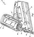
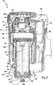
図1、2を参照すると、本発明の通気チェック弁を組込んだ、燃焼動力式釘打ち機としても知られている燃焼動力式締結具駆動工具が、全体的に参照番号10にて指示されている。該燃焼動力式締結具駆動工具は、好ましくは、本願と一体をなすものとして参照した上記の特許に詳細に説明されている一般的なタイプの工具である。工具10のハウジング12が、ハウジング主室16内に内蔵された内部動力源14(図2)を包囲する。従来の燃焼工具と同様に、動力源つまり内燃エンジン14は内部燃焼によって動力を発生し、シリンダ20に連通する燃焼室18を有している。シリンダ20内に往復動自在に配設されたピストン22が、駆動ブレード24の上端に連結されている。図2に示すように、ピストン22の往復動作の上限は点火前位置と称され、そしてそれは点火の直前の、つまり、燃焼性ガスに点火し、締結具(図示せず)に衝当してワークに押し込むために、駆動ブレード24の下方への駆動が開始する直前の位置である。
Referring to FIGS. 1 and 2, a combustion powered fastener drive tool, also known as a combustion powered nailing machine, incorporating the ventilation check valve of the present invention is generally designated by the
トリガースイッチ(図示せず)を組込んだトリガー26(本明細書では、トリガーおよびトリガースイッチとの語は、相互に入替えて使用されている)を押込むことによって、操作者は、燃焼室18内に燃焼を引き起こし、駆動ブレード24がノーズ部28(図1)内を下方へ駆動される。ノーズ部28は、締結具マガジン30によってノーズ部内に給送された締結具に衝当させるために、駆動ブレード24を案内する。
By depressing a trigger 26 (in this document, the terms trigger and trigger switch are used interchangeably) incorporating a trigger switch (not shown), the operator can Combustion is caused inside, and the
ノーズ部28に隣接させてワーク接触要素32が設けられており、該ワーク接触要素は、往復動する弁スリーブ36にリンク機構34を介して連結されている。弁スリーブの上端は、燃焼室18の一部を画成する。図1に示すように、工具のハウジング12をワーク接触要素32に対して下方(周知となっているように、他の操作方向でもよい)へ押込むと、ワーク接触要素は休止位置から点火前位置へ移動する。この移動は、バネ38(図1では隠れている)によるワーク接触要素32の通常下方への付勢に対抗して行われる。バネ38の位置は他の位置でもよい。
A
リンク機構34を通じて、ワーク接触要素32は、弁スリーブ36に連結され、該弁スリーブと共に往復動作する。休止位置(図2)では、弁スリーブ36とシリンダヘッド42とを隔てる上方間隙40U、および、弁スリーブ36とシリンダ20とを隔てる下間隙法40Lがあるので、燃焼室18は密閉されていない。前記シリンダヘッドには、スパークプラグ46が配設されている。弁スリーブ36の位置を監視するために、該弁スリーブの近傍に燃焼室スイッチ44が配設されている。本工具10の好ましい実施形態では、シリンダヘッド42は、また、冷却ファン48および該冷却ファンを駆動するファンモータ49のための取付部となっている。該ファンモータ一部は、周知のように、また、本願と一体をなすものとして参照した上記特許に記載されているように、燃焼室18内に突き出ている。図2に示す休止位置では、燃焼室18は、シリンダヘッド42およびシリンダ20により密閉されておらず、また、燃焼室スイッチ44が開成しているので、工具10は点火不能となっている。
Through the
操作者がワーク接触要素32をワークに押圧すると、点火可能となる。この操作は、バネの付勢力に対抗して行われ、これによって弁スリーブ36がハウジング12に関して上動し、間隙40U、40Lが閉じ、燃焼室18が密閉され、燃焼室スイッチ44が起動する。この操作によって、また、計量された量の燃料が燃料キャニスター50(部分的に示されている)から燃焼室18内に供給される。
When the operator presses the
トリガー26が引かれると、点火プラグ46が活性化し、燃焼室18内の燃料と空気の混合気が点火し、ピストン22および駆動ブレード24が、ワークへ打込むために待機している締結具へ向けて下方へ送出される。ピストン22がシリンダを下方へ移動すると、該ピストンは空気を押して、少なくとも1つのペタル弁(petal valve)、リード弁または逆止弁52、および、ピストンの移動行程を越えた位置(図2)に配置されている少なくとも1つの通気ポートまたは通気孔53、以下、単にポートと称する、を介して排気する。ピストン行程の下端つまりピストンの最大移動距離の位置で、周知のようにピストン22は弾性バンパー54に衝接する。ピストン22が排気逆止弁52を越えると、シリンダ20から高圧気体が排気される。残留気体の冷却によるシリンダ20内の内部圧力の違いによって、ピストン22は図2に示す点火前位置へ復帰する。
When the
ピストンの復帰に差圧を利用する燃焼動力式釘打ち機では、ピストン22の非燃焼側に大気圧が作用する。ポート54によって、工具の内側と外側とが連通する。駆動行程中に適正な動力性能を確保するサイズにポート54を形成した釘打ち機もある。これによって、ピストン22に作用する行程容積によるエアブレーキが低減され、動力損失を生じる。ポート54の面積は、しばしば、ピストン22を効果的に復帰させるのに必要な最大面積よりも大きくなっている。ポート面積が大きければ大きいほど、塵埃、汚染物質は工具10へ侵入し易くなる。
In a combustion-powered nailing machine that uses differential pressure to return the piston, atmospheric pressure acts on the non-combustion side of the
本発明の釘打ち機10は、工具10の駆動サイクル中に必要な空気流量が、ピストンの復帰に必要な空気量よりも大きいので、流量を調整するために、通気チェック弁または流量制限弁60をポート54に配設している点を1つの特徴としている。ピストン22が行程の終点に到達しバンパ56に衝接するとき、固有のチェック弁オフセット圧力が克服されると、チェック弁60は、シリンダ20からの空気の流出を許容する。チェック弁60の重要な特徴は、戻り空気の流れを完全に止めるのではなく、上述したピストンの駆動行程での排気よりも少ない、制限された流入を許容する点である。制限された流入量は、用途に応じて変えることができるが、好ましくは、効果的にピストンを復帰させるのに必要な最低流量である。最小面積は、工具の他の領域に接続または配管でつなげることのできる単一のポートまたは複数のポートとすることができる。
In the nailing
図2に示すように、チェック弁60は、好ましくは、ポート54に隣接させてシリンダ20を囲繞し、また、好ましくは、十分な空気圧力を受けたときに容易に膨張するゴム状のフラップまたはバネ鋼より成る帯部材である。リードペタル(reed petal)やバネによって付勢されたプレート、ボール弁のような一方向の流れを作る他の手段であってもよい。他のタイプの取付方も考えられるが、チェック弁60は、好ましくは、半径方向内側に突出したリップ部64を環状溝66に係合させることによって、シリンダ20の上端部62に固定される。
As shown in FIG. 2, the
外気が制限された流量で流入できるようにするために、ウェブ部分68にはポート54に連通する少なくとも1つの小孔70が設けられている。然しながら、該小孔は、空気の流れが内向きとなる限り、対応のポートに直接的に配置しなくともよい。更に、小孔70の断面積は、ポート54の断面積よりも大きくまたは小さくすることができる。図2に示すように、小孔70の断面積は、関連したポート54の断面積よりも小さくなっている。小孔70の個数は、用途に応じて変更することができ、小孔の個数はポート54の個数よりも多く或いは少なくすることができる。また、少なくとも1つのポート54は、チェック弁60の一部によって覆われたり或いは阻害されたりしないようにしてもよい(図2A参照)。
The
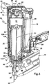
図3を参照すると、本発明の他の実施形態による通気チェック弁を備えた燃焼動力式釘打ち機が全体的に参照番号80にて指示されている。釘打ち機10と同様の構成要素には同じ参照番号が付されている。また、釘打ち機80は、好ましくは、釘打ち機10の特徴の全てを含むように構成されている。
Referring to FIG. 3, a combustion powered nailer with a vent check valve according to another embodiment of the present invention is indicated generally by the
ハウジング12にはキャップ82に設けられており、該キャップはハウジングの上端84を閉鎖し、また、該キャップには空気入口88を有した空気入口端部86が形成されている。この技術分野において知られているように、空気フィルタ90がキャップ82に関連させて設けられており、保護格子92によって支持されている。この技術分野において周知となっているように、空気フィルタ90は、着脱自在にキャップ82に固定されている。空気フィルタ90は、プラスチックメッシュや金属メッシュ、発泡材料のような多孔性の材料から形成されており、ハウジング12内へ空気が流入が可能となっているが、破片や塵埃その他の操作上の汚染物質の進入は防止される。
The
上端84の反対側の工具80の下端96には、ノーズ部28に駆動ブレード通路98が設けられている。該駆動ブレード通路には、駆動ブレード24がスライド自在に配設されている。エンドプレート100には中心穴102が形成されており、作動中にピストン22が往復動作すると、駆動ブレード24が空気と共に該中心穴を通過する。従って、中心穴102を空気ポートとして称することができよう。然しながら、ポート54はこうした空気ポートと考えることができ、また、エンドプレート100やシリンダ20の下方部分に他の空気ポートを設けることもできる。
A
通路98内での駆動ブレード24の相対的なスライド動作を許容しながら、空気ポートから空気がノーズ部へ向けて流出することを防止するために、グロメットまたはワイピングシール104が、シリンダ20の下端においてノーズ部28の上端の直ぐ上側に配置されている。
A grommet or wiping
釘打ち機80の1つの重要な特徴は、少なくとも1つの空気ポート54、102に連通し、かつ、空気フィルタ90と協働する、参照番号106で指示する少なくとも1つの空気通路を設けた点である。少なくとも1つの空気通路106によって、シリンダ20の下端と空気フィルタ90ならびに空気入口端部86との間が連通(好ましくは、作動流体は空気)する。好ましい実施形態では、空気フィルタ90は工具10に流入する空気を濾過するために設けられているが、特に通路106との連津のために、空気入口端部と関連する付加的な空気フィルタまたは専用空気フィルタを設けてもよい。明確に示すために、代表としてフィルタ90のみを説明する。
One important feature of
ピストン22が、図2に示す点火前位置に復帰する際にシリンダ20に流入する空気は、先ず、フィルタ90を通過しなければならない。また、燃焼サイクル中に、空気は、空気ポート54ならびに通気チェック弁60から排気される。
When the
好ましい実施形態では、通路106は、相互接続管とも称する、少なくとも1つの管の形態で設けられており、ピストン22の作動軸に関して概ね平行な中央部分108と、上端部分110と下端部分112とを有している。上端部分と下端部分は、夫々、空気入口端部および空気ポート54に接続するために、中央部分に関して概ね直角に突出し半径ベンド部として形成されている。上端部分110および下端部分112の特定の角度配向は、状況に適合するように変更することができよう。少なくとも1本の連続管が図示されているが、通路106は、所定角度のフィッティングによって接合された複数の管部分から形成したり、或いは、完成した組立体の中で通路を形成する個々の要素形態で形成することができよう。
In a preferred embodiment, the
より詳細には、上端部分110は、好ましくは、キャップ82によってフィルタ90の下側に形成される空気室114内に固定される。上端部分110を固定するための従来の技術には、以下に限定されないが、摩擦嵌合、化学的接着剤、クリップ、剛体フィッティング等が含まれよう。上端部分110は、空気フィルタ90の下流にあるハウジングの主室16に連通していることは理解されよう。
More specifically, the
通路106の中央部分108と、上端部分110および下端部分112の少なくとも主要部分とが、内燃エンジン14に沿って、ハウジング12内に好ましく延設されている。必要で有れば、ハウジング12は、通路106を包含するように半径方向に膨出させることができる。更に他の実施形態では、通路106は、ハウジング12と一体成形される。また、通路106は、ハウジング12の外部に配置してもよい。通路106は、好ましくは、一般的に燃焼動力式釘打ち機で経験する、ありうる衝撃や温度に耐える十分な耐久性ある管製作法によって製造される。
A
下端部分112において、通路106は、排気開口部または空気ポート54を介してシリンダ20内部と連通する。下端部分がシリンダ20内に突出しないようにして、ピストン22との干渉を防止することは好ましい。然しながら、突出した管であっても、シリンダへの入口点がピストン行程の最下点よりも低い位置にあれば許容できる。下端部分112は、最終的に、シリンダ20の下方部分に固定され、かつ、通気チェック弁60および少なくとも1つの小孔70を貫通して連通を維持する。上端部分110に関連して既述した固定技術と同様の技術を用いて、下端部分112が正しい位置に固定される。全ての小孔70が、マニフォールド(図示せず)またはこの技術分野で公知の適当なコネクター継手によって、通路106に連通することは理解されよう。然しながら、燃焼が完了したときの排気ガスが、ピストンの復帰に必要な吸気量と比較して大量な場合には、小孔70が設けられておらず通路106に連通していない付加的な排気開口部54を設けてもよい。
In the
通路106の断面積は、ピストンを復帰可能とする空気量だけが流入するように決定される。この面積は、釘打ち機80のタイプおよび燃焼動力源14の大きさによって変わる。
The cross-sectional area of the
図2を参照すると、グローメットまたはワイピングシール104に代えて、交換可能なプラグ118が設けられている。該プラグは、駆動ブレード通路98内に固定可能で、かつ、駆動ブレード24をスライド自在に収容する開口部120を有している。
Referring to FIG. 2, a replaceable plug 118 is provided in place of the grommet or wiping
図4を参照すると、本発明の他の実施形態が全体的に参照番号130にて指示されており、また、釘打ち機10、80と同様の構成要素には同じ参照番号が付されている。釘打ち機10、80は類似する構成を有している。工具130では、通路132はハウジング12の外部に形成されている。
Referring to FIG. 4, another embodiment of the present invention is indicated generally by
工具130と工具80との主要な相違点は、通路132の上端部分134が空気入口88ではなくて、ハウジング12の上端部分138に特別に形成された補助空気入口136に連通している点である。然しながら、空気入口88、136の双方は、好ましくは、空気入口端部86に或いは該空気入口端部に隣接させて設けられている。補助空気入口136には、好ましくは、専用のフィルタ140、保護格子142、補助空気室144が設けられており、該補助空気室によって、上端部分134が連通するようになっている。フィルタ140、保護格子142および補助空気室144を省略した応用例もあろう。また、少なくとも1つの補助空気入口136をハウジング内で燃焼動力源14の高い作動温度に関して十分に離した適当な位置に配置したような構成も考え得る。
The main difference between the
通路132の上端部分134は、鉛直に突出した中央部分146の延長部分として図示されているが、角度を以て配向させたり、他の構成も可能である。釘打ち機10、80の場合と同様に、通路132はハウジング12の周縁部に図示されているが、内部に配置してもよい。実施形態130の作用は、実施形態80に関連した上述した作用と実質的に同じであるが、主要な差異は、補助空気室144からは燃焼動力源14、より詳細には燃焼室18へは空気が供給されない点である。
Although the
釘打ち機130の他の特徴は、図3に示すように、通路132の下端部分112を通気チェック弁60および関連する小孔70を貫通させることができる点である。また、通路132は、参照番号148で示すように、シリンダ20および関する空気ポート54aを直接貫通させて、通気チェック弁60とは独立にシリンダ内に導入するようにしてもよい。こうした構成は、また、図3に示す工具80でも可能である。図4の実施形態では、通気チェック弁60は、該チェック弁の作用を阻害することなく、通路132とポート54aとが直接係合するように構成することもできよう。
Another feature of the nailing
こうして、本発明は、燃焼が生じたときに、選択的に空気の戻りを吸引するための通気チェック弁を特徴とする。実施されると、本発明の通気チェック弁システムによれば、工具のメンテナンスが少なくなり、必要な潤滑剤が低減され、損耗が低減され、スリーブの内側と外側との間の連通が一層安定する。 Thus, the present invention features a vent check valve for selectively aspirating air return when combustion occurs. When implemented, the vent check valve system of the present invention reduces tool maintenance, reduces required lubricant, reduces wear, and provides more stable communication between the inside and outside of the sleeve. .
燃焼動力式釘打ち機用の本発明による通気チェック弁の特定の実施形態を説明したが、本発明の広い特徴の範囲および特許請求の範囲から逸脱することなく、その変更と修正が可能であることは当業者の当然とするところである。 While a particular embodiment of the aeration check valve according to the present invention for a combustion powered nailer has been described, changes and modifications can be made without departing from the broad features and scope of the present invention. This is obvious to those skilled in the art.
10 燃焼動力式釘打ち機
12 ハウジング
14 内燃エンジン
20 シリンダ
22 ピストン
24 駆動ブレード
52 排気弁
54 空気ポート
60 通気チェック弁
70 小孔
80 燃焼動力式釘打ち機
88 空気入口
90 空気フィルタ
98 駆動ブレード通路
102 空気ポート
104 グロメットまたはワイピングシール
106 空気通路
108 中央部分
110 上端部分
112 下端部分
118 交換可能なプラグ
114 空気室
130 燃焼動力式釘打ち機
136 空気入口
DESCRIPTION OF
Claims (16)
シリンダ(20)、および、点火前位置と最大伸長位置との間で往復するピストン(22)を有した内燃エンジン(14)と、
前記最大伸長位置よりも下側に前記シリンダ(20)に設けられた少なくとも1つの空気ポート(54、102)とを具備し、
前記少なくとも1つの空気ポートを通って前記シリンダから排気される体積が流入量よりも大きくなるように形成された通気チェック弁(60)が前記少なくとも1つの空気ポートに設けられている燃焼動力式釘打ち機。In a combustion powered nailer (10, 80, 130) designed to reduce the suction of contaminated air during operation,
An internal combustion engine (14) having a cylinder (20) and a piston (22) reciprocating between a pre-ignition position and a maximum extension position;
Comprising at least one air port (54, 102) provided in the cylinder (20) below the maximum extension position;
A combustion powered nail in which a ventilation check valve (60) formed so that a volume exhausted from the cylinder through the at least one air port is larger than an inflow amount is provided in the at least one air port. Hammering machine.
前記駆動ブレードの往復動作を可能としながら前記前記シリンダ内への空気の流れを制限するための、前記開口部に配設された少なくとも1つのシール部材(104)とを更に具備する請求項1に記載の燃焼動力式釘打ち機。A drive blade passage (98) formed in the cylinder (20) to receive a drive blade (24) attached to the piston (22);
The apparatus of claim 1, further comprising at least one seal member (104) disposed in the opening for restricting air flow into the cylinder while allowing the drive blade to reciprocate. The combustion-powered nailer described.
前記少なくとも1つの空気入口と、少なくとも1つの空気ポート(54)とに連通する少なくとも1つの空気通路(106)とを更に具備する請求項1に記載の燃焼動力式釘打ち機。At least one air inlet (88, 136) disposed in the tool housing (12);
The combustion-powered nailer according to claim 1, further comprising at least one air passage (106) in communication with the at least one air inlet and at least one air port (54).
Applications Claiming Priority (5)
| Application Number | Priority Date | Filing Date | Title |
|---|---|---|---|
| US66211205P | 2005-03-15 | 2005-03-15 | |
| US60/662,112 | 2005-03-15 | ||
| US11/182,208 | 2005-07-15 | ||
| US11/182,208 US7314025B2 (en) | 2005-07-15 | 2005-07-15 | Combustion powered fastener-driving tool with interconnected chambers |
| PCT/US2006/008837 WO2006101789A1 (en) | 2005-03-15 | 2006-03-13 | Venting check valve for combustion nailer |
Publications (3)
| Publication Number | Publication Date |
|---|---|
| JP2008532787A JP2008532787A (en) | 2008-08-21 |
| JP2008532787A5 JP2008532787A5 (en) | 2009-03-26 |
| JP4897787B2 true JP4897787B2 (en) | 2012-03-14 |
Family
ID=37024124
Family Applications (1)
| Application Number | Title | Priority Date | Filing Date |
|---|---|---|---|
| JP2008501931A Expired - Fee Related JP4897787B2 (en) | 2005-03-15 | 2006-03-13 | Ventilation check valve for combustion powered nailer |
Country Status (11)
| Country | Link |
|---|---|
| US (1) | US7591236B2 (en) |
| EP (1) | EP1858671B1 (en) |
| JP (1) | JP4897787B2 (en) |
| KR (1) | KR20070108238A (en) |
| CN (1) | CN101142060B (en) |
| AT (1) | ATE440704T1 (en) |
| AU (1) | AU2006227796B2 (en) |
| CA (1) | CA2599443C (en) |
| DE (1) | DE602006008754D1 (en) |
| NZ (1) | NZ561444A (en) |
| WO (1) | WO2006101789A1 (en) |
Families Citing this family (14)
| Publication number | Priority date | Publication date | Assignee | Title |
|---|---|---|---|---|
| US7314025B2 (en) * | 2005-07-15 | 2008-01-01 | Illinois Tool Works Inc. | Combustion powered fastener-driving tool with interconnected chambers |
| JP4886068B2 (en) * | 2008-06-04 | 2012-02-29 | 株式会社東亜利根ボーリング | Shock absorber shock absorber |
| US8016046B2 (en) | 2008-09-12 | 2011-09-13 | Illinois Tool Works Inc. | Combustion power source with back pressure release for combustion powered fastener-driving tool |
| US9844864B2 (en) | 2012-02-10 | 2017-12-19 | Illinois Tool Works Inc. | Sleeve for a pneumatic fastener-driving tool |
| FR2988634B1 (en) * | 2012-04-03 | 2014-03-21 | Illinois Tool Works | REMOVABLE ADAPTER FOR ADMISSION AND MIXING OF AIR AND FUEL FOR A COMBUSTION TOOL |
| WO2014020606A1 (en) * | 2012-07-31 | 2014-02-06 | Eitan Furst | A method and system for controlling liquid flow |
| US9638092B2 (en) * | 2014-06-20 | 2017-05-02 | Joseph S. Adams | Combustion-powered tool with flexible silicone control check valve operable between a primary combustion chamber and a secondary combustion chamber |
| US11554471B2 (en) * | 2014-08-28 | 2023-01-17 | Power Tech Staple and Nail, Inc. | Elastomeric exhaust reed valve for combustion driven fastener hand tool |
| US9862083B2 (en) | 2014-08-28 | 2018-01-09 | Power Tech Staple and Nail, Inc. | Vacuum piston retention for a combustion driven fastener hand tool |
| US10759031B2 (en) | 2014-08-28 | 2020-09-01 | Power Tech Staple and Nail, Inc. | Support for elastomeric disc valve in combustion driven fastener hand tool |
| EP3325218A4 (en) * | 2015-07-23 | 2019-05-08 | Power Tech Staple And Nail, Inc. | Elastomeric exhaust reed valve for combustion driven fastener hand tool |
| EP3184248A1 (en) * | 2015-12-22 | 2017-06-28 | HILTI Aktiengesellschaft | Combustion-driven setting tool and method for operating such a setting tool |
| US11624314B2 (en) | 2018-08-21 | 2023-04-11 | Power Tech Staple and Nail, Inc. | Combustion chamber valve and fuel system for driven fastener hand tool |
| CN111779723B (en) * | 2020-05-20 | 2022-07-19 | 广东明晖气动科技有限公司 | Pneumatic valve of pneumatic nail gun |
Citations (4)
| Publication number | Priority date | Publication date | Assignee | Title |
|---|---|---|---|---|
| JPS6328574A (en) * | 1986-07-02 | 1988-02-06 | センコ、プロダクツ、インコ | Simple built-in internal combustion type fastener driving tool |
| JPS6328573A (en) * | 1986-07-18 | 1988-02-06 | 日立工機株式会社 | Scavenging structure of gas combustion type driving machine |
| JPS63174883A (en) * | 1987-01-08 | 1988-07-19 | ポウーアール・トゥールズ・コーポレーション | Initiation type impact tool |
| JP2005040875A (en) * | 2003-07-24 | 2005-02-17 | Makita Corp | Combustion power tool |
Family Cites Families (13)
| Publication number | Priority date | Publication date | Assignee | Title |
|---|---|---|---|---|
| US3278103A (en) * | 1965-04-06 | 1966-10-11 | Senco Products | Fastener applying device |
| DE1503033A1 (en) * | 1965-07-09 | 1969-12-04 | Reich Maschf Gmbh Karl | Pneumatic nailer |
| US4401251A (en) * | 1980-11-19 | 1983-08-30 | Signode Corporation | Bumperless gun nailer |
| IN157475B (en) * | 1981-01-22 | 1986-04-05 | Signode Corp | |
| US4403722A (en) * | 1981-01-22 | 1983-09-13 | Signode Corporation | Combustion gas powered fastener driving tool |
| US4483473A (en) * | 1983-05-02 | 1984-11-20 | Signode Corporation | Portable gas-powered fastener driving tool |
| US4717060A (en) * | 1986-07-02 | 1988-01-05 | Senco Products, Inc. | Self-contained internal combustion fastener driving tool |
| US5199626A (en) * | 1990-10-05 | 1993-04-06 | Hitachi Koki Company Limited | Combustion gas powered tool |
| US5909836A (en) * | 1997-10-31 | 1999-06-08 | Illinois Tool Works Inc. | Combustion powered tool with combustion chamber lockout |
| US6116489A (en) * | 1998-10-28 | 2000-09-12 | Pow-R-Tools Corporation | Manually operable internal combustion-type impact tool with reduced recycler stroke |
| CN2415886Y (en) * | 2000-04-30 | 2001-01-24 | 喻启平 | Pneumatic nailing gun |
| JP4144472B2 (en) * | 2003-08-11 | 2008-09-03 | 日立工機株式会社 | Combustion power tool |
| US7201301B2 (en) * | 2004-02-09 | 2007-04-10 | Illinois Tool Works Inc. | Exhaust system for combustion-powered fastener-driving tool |
-
2006
- 2006-03-13 WO PCT/US2006/008837 patent/WO2006101789A1/en active Application Filing
- 2006-03-13 NZ NZ561444A patent/NZ561444A/en not_active IP Right Cessation
- 2006-03-13 CN CN2006800081676A patent/CN101142060B/en not_active Expired - Fee Related
- 2006-03-13 KR KR1020077020783A patent/KR20070108238A/en not_active Application Discontinuation
- 2006-03-13 AU AU2006227796A patent/AU2006227796B2/en not_active Ceased
- 2006-03-13 JP JP2008501931A patent/JP4897787B2/en not_active Expired - Fee Related
- 2006-03-13 AT AT06737955T patent/ATE440704T1/en not_active IP Right Cessation
- 2006-03-13 CA CA2599443A patent/CA2599443C/en not_active Expired - Fee Related
- 2006-03-13 DE DE602006008754T patent/DE602006008754D1/en active Active
- 2006-03-13 EP EP06737955A patent/EP1858671B1/en not_active Not-in-force
- 2006-03-13 US US11/885,894 patent/US7591236B2/en active Active
Patent Citations (4)
| Publication number | Priority date | Publication date | Assignee | Title |
|---|---|---|---|---|
| JPS6328574A (en) * | 1986-07-02 | 1988-02-06 | センコ、プロダクツ、インコ | Simple built-in internal combustion type fastener driving tool |
| JPS6328573A (en) * | 1986-07-18 | 1988-02-06 | 日立工機株式会社 | Scavenging structure of gas combustion type driving machine |
| JPS63174883A (en) * | 1987-01-08 | 1988-07-19 | ポウーアール・トゥールズ・コーポレーション | Initiation type impact tool |
| JP2005040875A (en) * | 2003-07-24 | 2005-02-17 | Makita Corp | Combustion power tool |
Also Published As
| Publication number | Publication date |
|---|---|
| CA2599443C (en) | 2010-09-21 |
| DE602006008754D1 (en) | 2009-10-08 |
| US20080169326A1 (en) | 2008-07-17 |
| AU2006227796A1 (en) | 2006-09-28 |
| AU2006227796B2 (en) | 2010-04-22 |
| JP2008532787A (en) | 2008-08-21 |
| US7591236B2 (en) | 2009-09-22 |
| EP1858671A4 (en) | 2008-04-02 |
| EP1858671B1 (en) | 2009-08-26 |
| CN101142060B (en) | 2010-05-19 |
| ATE440704T1 (en) | 2009-09-15 |
| KR20070108238A (en) | 2007-11-08 |
| EP1858671A1 (en) | 2007-11-28 |
| CA2599443A1 (en) | 2006-09-28 |
| CN101142060A (en) | 2008-03-12 |
| WO2006101789A1 (en) | 2006-09-28 |
| NZ561444A (en) | 2010-12-24 |
Similar Documents
| Publication | Publication Date | Title |
|---|---|---|
| JP4897787B2 (en) | Ventilation check valve for combustion powered nailer | |
| EP1910036B1 (en) | Combustion powered fastener-driving tool with interconnected chambers | |
| CA2735399C (en) | Combustion power source with back pressure release for combustion powered fastener-driving tool | |
| EP1893387B1 (en) | Combustion nailer with a temperature sensor | |
| NZ548482A (en) | Exhaust system for combustion-powered fastener-driving tool | |
| EP1954448B1 (en) | One way valve for combustion tool fan motor | |
| NZ568395A (en) | Fan motor control for a combustion nailer based on the operating mode of the nailer | |
| TWI587988B (en) | High efficiency pneumatic nailer | |
| AU2009292089B9 (en) | Combustion power source with back pressure release for combustion powered fastener-driving tool |
Legal Events
| Date | Code | Title | Description |
|---|---|---|---|
| A521 | Request for written amendment filed |
Free format text: JAPANESE INTERMEDIATE CODE: A523 Effective date: 20090204 |
|
| A621 | Written request for application examination |
Free format text: JAPANESE INTERMEDIATE CODE: A621 Effective date: 20090204 |
|
| TRDD | Decision of grant or rejection written | ||
| A01 | Written decision to grant a patent or to grant a registration (utility model) |
Free format text: JAPANESE INTERMEDIATE CODE: A01 Effective date: 20111122 |
|
| A01 | Written decision to grant a patent or to grant a registration (utility model) |
Free format text: JAPANESE INTERMEDIATE CODE: A01 |
|
| A61 | First payment of annual fees (during grant procedure) |
Free format text: JAPANESE INTERMEDIATE CODE: A61 Effective date: 20111222 |
|
| R150 | Certificate of patent or registration of utility model |
Free format text: JAPANESE INTERMEDIATE CODE: R150 |
|
| FPAY | Renewal fee payment (event date is renewal date of database) |
Free format text: PAYMENT UNTIL: 20150106 Year of fee payment: 3 |
|
| R250 | Receipt of annual fees |
Free format text: JAPANESE INTERMEDIATE CODE: R250 |
|
| R250 | Receipt of annual fees |
Free format text: JAPANESE INTERMEDIATE CODE: R250 |
|
| R250 | Receipt of annual fees |
Free format text: JAPANESE INTERMEDIATE CODE: R250 |
|
| LAPS | Cancellation because of no payment of annual fees |