JP4895881B2 - Pipe fitting for high pressure fluid - Google Patents
Pipe fitting for high pressure fluid Download PDFInfo
- Publication number
- JP4895881B2 JP4895881B2 JP2007075506A JP2007075506A JP4895881B2 JP 4895881 B2 JP4895881 B2 JP 4895881B2 JP 2007075506 A JP2007075506 A JP 2007075506A JP 2007075506 A JP2007075506 A JP 2007075506A JP 4895881 B2 JP4895881 B2 JP 4895881B2
- Authority
- JP
- Japan
- Prior art keywords
- valve seat
- seal ring
- outer peripheral
- setting
- pressure fluid
- Prior art date
- Legal status (The legal status is an assumption and is not a legal conclusion. Google has not performed a legal analysis and makes no representation as to the accuracy of the status listed.)
- Active
Links
- 239000012530 fluid Substances 0.000 title claims description 99
- 230000002093 peripheral effect Effects 0.000 claims description 75
- 238000011144 upstream manufacturing Methods 0.000 claims description 15
- 238000004891 communication Methods 0.000 claims description 12
- 238000007789 sealing Methods 0.000 claims description 4
- UFHFLCQGNIYNRP-UHFFFAOYSA-N Hydrogen Chemical compound [H][H] UFHFLCQGNIYNRP-UHFFFAOYSA-N 0.000 description 31
- 230000006835 compression Effects 0.000 description 3
- 238000007906 compression Methods 0.000 description 3
- 239000000470 constituent Substances 0.000 description 1
- 230000008878 coupling Effects 0.000 description 1
- 238000010168 coupling process Methods 0.000 description 1
- 238000005859 coupling reaction Methods 0.000 description 1
- 238000007599 discharging Methods 0.000 description 1
- 239000000446 fuel Substances 0.000 description 1
- 239000007789 gas Substances 0.000 description 1
- 239000001257 hydrogen Substances 0.000 description 1
- 229910052739 hydrogen Inorganic materials 0.000 description 1
- 239000007788 liquid Substances 0.000 description 1
- 238000012423 maintenance Methods 0.000 description 1
- 239000002184 metal Substances 0.000 description 1
- 230000000149 penetrating effect Effects 0.000 description 1
Images
Classifications
-
- F—MECHANICAL ENGINEERING; LIGHTING; HEATING; WEAPONS; BLASTING
- F16—ENGINEERING ELEMENTS AND UNITS; GENERAL MEASURES FOR PRODUCING AND MAINTAINING EFFECTIVE FUNCTIONING OF MACHINES OR INSTALLATIONS; THERMAL INSULATION IN GENERAL
- F16L—PIPES; JOINTS OR FITTINGS FOR PIPES; SUPPORTS FOR PIPES, CABLES OR PROTECTIVE TUBING; MEANS FOR THERMAL INSULATION IN GENERAL
- F16L37/00—Couplings of the quick-acting type
- F16L37/28—Couplings of the quick-acting type with fluid cut-off means
- F16L37/38—Couplings of the quick-acting type with fluid cut-off means with fluid cut-off means in only one of the two pipe-end fittings
- F16L37/40—Couplings of the quick-acting type with fluid cut-off means with fluid cut-off means in only one of the two pipe-end fittings with a lift valve being opened automatically when the coupling is applied
- F16L37/42—Couplings of the quick-acting type with fluid cut-off means with fluid cut-off means in only one of the two pipe-end fittings with a lift valve being opened automatically when the coupling is applied the valve having an axial bore communicating with lateral apertures
-
- F—MECHANICAL ENGINEERING; LIGHTING; HEATING; WEAPONS; BLASTING
- F16—ENGINEERING ELEMENTS AND UNITS; GENERAL MEASURES FOR PRODUCING AND MAINTAINING EFFECTIVE FUNCTIONING OF MACHINES OR INSTALLATIONS; THERMAL INSULATION IN GENERAL
- F16K—VALVES; TAPS; COCKS; ACTUATING-FLOATS; DEVICES FOR VENTING OR AERATING
- F16K15/00—Check valves
- F16K15/02—Check valves with guided rigid valve members
- F16K15/06—Check valves with guided rigid valve members with guided stems
- F16K15/063—Check valves with guided rigid valve members with guided stems the valve being loaded by a spring
-
- F—MECHANICAL ENGINEERING; LIGHTING; HEATING; WEAPONS; BLASTING
- F16—ENGINEERING ELEMENTS AND UNITS; GENERAL MEASURES FOR PRODUCING AND MAINTAINING EFFECTIVE FUNCTIONING OF MACHINES OR INSTALLATIONS; THERMAL INSULATION IN GENERAL
- F16L—PIPES; JOINTS OR FITTINGS FOR PIPES; SUPPORTS FOR PIPES, CABLES OR PROTECTIVE TUBING; MEANS FOR THERMAL INSULATION IN GENERAL
- F16L37/00—Couplings of the quick-acting type
- F16L37/22—Couplings of the quick-acting type in which the connection is maintained by means of balls, rollers or helical springs under radial pressure between the parts
- F16L37/23—Couplings of the quick-acting type in which the connection is maintained by means of balls, rollers or helical springs under radial pressure between the parts by means of balls
-
- F—MECHANICAL ENGINEERING; LIGHTING; HEATING; WEAPONS; BLASTING
- F16—ENGINEERING ELEMENTS AND UNITS; GENERAL MEASURES FOR PRODUCING AND MAINTAINING EFFECTIVE FUNCTIONING OF MACHINES OR INSTALLATIONS; THERMAL INSULATION IN GENERAL
- F16L—PIPES; JOINTS OR FITTINGS FOR PIPES; SUPPORTS FOR PIPES, CABLES OR PROTECTIVE TUBING; MEANS FOR THERMAL INSULATION IN GENERAL
- F16L37/00—Couplings of the quick-acting type
- F16L37/28—Couplings of the quick-acting type with fluid cut-off means
- F16L37/38—Couplings of the quick-acting type with fluid cut-off means with fluid cut-off means in only one of the two pipe-end fittings
- F16L37/44—Couplings of the quick-acting type with fluid cut-off means with fluid cut-off means in only one of the two pipe-end fittings with one lift valve being actuated to initiate the flow through the coupling after the two coupling parts are locked against withdrawal
-
- F—MECHANICAL ENGINEERING; LIGHTING; HEATING; WEAPONS; BLASTING
- F17—STORING OR DISTRIBUTING GASES OR LIQUIDS
- F17C—VESSELS FOR CONTAINING OR STORING COMPRESSED, LIQUEFIED OR SOLIDIFIED GASES; FIXED-CAPACITY GAS-HOLDERS; FILLING VESSELS WITH, OR DISCHARGING FROM VESSELS, COMPRESSED, LIQUEFIED, OR SOLIDIFIED GASES
- F17C2205/00—Vessel construction, in particular mounting arrangements, attachments or identifications means
- F17C2205/03—Fluid connections, filters, valves, closure means or other attachments
- F17C2205/0302—Fittings, valves, filters, or components in connection with the gas storage device
- F17C2205/037—Quick connecting means, e.g. couplings
-
- Y—GENERAL TAGGING OF NEW TECHNOLOGICAL DEVELOPMENTS; GENERAL TAGGING OF CROSS-SECTIONAL TECHNOLOGIES SPANNING OVER SEVERAL SECTIONS OF THE IPC; TECHNICAL SUBJECTS COVERED BY FORMER USPC CROSS-REFERENCE ART COLLECTIONS [XRACs] AND DIGESTS
- Y02—TECHNOLOGIES OR APPLICATIONS FOR MITIGATION OR ADAPTATION AGAINST CLIMATE CHANGE
- Y02E—REDUCTION OF GREENHOUSE GAS [GHG] EMISSIONS, RELATED TO ENERGY GENERATION, TRANSMISSION OR DISTRIBUTION
- Y02E60/00—Enabling technologies; Technologies with a potential or indirect contribution to GHG emissions mitigation
- Y02E60/30—Hydrogen technology
- Y02E60/32—Hydrogen storage
-
- Y—GENERAL TAGGING OF NEW TECHNOLOGICAL DEVELOPMENTS; GENERAL TAGGING OF CROSS-SECTIONAL TECHNOLOGIES SPANNING OVER SEVERAL SECTIONS OF THE IPC; TECHNICAL SUBJECTS COVERED BY FORMER USPC CROSS-REFERENCE ART COLLECTIONS [XRACs] AND DIGESTS
- Y10—TECHNICAL SUBJECTS COVERED BY FORMER USPC
- Y10T—TECHNICAL SUBJECTS COVERED BY FORMER US CLASSIFICATION
- Y10T137/00—Fluid handling
- Y10T137/7722—Line condition change responsive valves
- Y10T137/7837—Direct response valves [i.e., check valve type]
- Y10T137/7854—In couplings for coaxial conduits, e.g., drill pipe check valves
-
- Y—GENERAL TAGGING OF NEW TECHNOLOGICAL DEVELOPMENTS; GENERAL TAGGING OF CROSS-SECTIONAL TECHNOLOGIES SPANNING OVER SEVERAL SECTIONS OF THE IPC; TECHNICAL SUBJECTS COVERED BY FORMER USPC CROSS-REFERENCE ART COLLECTIONS [XRACs] AND DIGESTS
- Y10—TECHNICAL SUBJECTS COVERED BY FORMER USPC
- Y10T—TECHNICAL SUBJECTS COVERED BY FORMER US CLASSIFICATION
- Y10T137/00—Fluid handling
- Y10T137/8593—Systems
- Y10T137/87917—Flow path with serial valves and/or closures
- Y10T137/87925—Separable flow path section, valve or closure in each
- Y10T137/87941—Each valve and/or closure operated by coupling motion
- Y10T137/87949—Linear motion of flow path sections operates both
Description
本発明は、水素ガスなどの高圧流体を扱うのに適した管継手部材に関する。 The present invention relates to a pipe joint member suitable for handling a high-pressure fluid such as hydrogen gas.
近年、水素ガスを使用した燃料電池を動力源とする車両が実用化されてきている。このような車両においては、現在主流のガソリン車両に対するガソリンスタンドと同様の水素ガス供給スタンドなどでの水素ガスの供給が必要となる。この場合、車両側の水素ガス貯留タンクの入口に取り付けられる管継手部材に対して、スタンド側の水素ガス貯留タンクからの水素ガスを排出供給するためのホースの出口に取り付けられた管継手部材を連結して、その供給が行われることになる。(特許文献1参照) In recent years, vehicles using a fuel cell using hydrogen gas as a power source have been put into practical use. In such a vehicle, it is necessary to supply hydrogen gas at a hydrogen gas supply station similar to a gas station for a currently mainstream gasoline vehicle. In this case, the pipe joint member attached to the outlet of the hose for discharging and supplying the hydrogen gas from the hydrogen gas storage tank on the stand side is connected to the pipe joint member attached to the inlet of the hydrogen gas storage tank on the vehicle side. It will be connected and the supply will be performed. (See Patent Document 1)
この場合の水素ガスは、30Mpa以上、通常は70Mpa程度に加圧されている。従って、そのような水素ガスの供給手段に用いられる管継手は、水素ガスが漏れないように万全のものが要求される。各管継手部材は、内部に開閉弁を装着する必要があるために、2つの筒状部材を軸線方向で整合して相互に嵌合連結して構成されるのが一般的である。従って、相互に嵌合される筒状部材の嵌合面の間の隙間や水素ガス供給完了後、筒状部材先端部から水素ガスが外部に漏洩しないようにシールリングが設定されることになるが、水素ガスが極めて高い加圧状態にあるため、該シールリングの設定には特に注意が必要となる。 The hydrogen gas in this case is pressurized to 30 Mpa or more, usually about 70 Mpa. Therefore, a pipe joint used for such a hydrogen gas supply means is required to be perfect so that hydrogen gas does not leak. Since each pipe joint member needs to be equipped with an on-off valve inside, it is general that two tubular members are aligned and fitted and connected to each other in the axial direction. Therefore, after the gap between the fitting surfaces of the cylindrical members to be fitted to each other and the hydrogen gas supply completion, the seal ring is set so that hydrogen gas does not leak to the outside from the tip of the cylindrical member. However, since hydrogen gas is in a very high pressure state, special attention is required for setting the seal ring.
本発明は、このような点に鑑み、水素ガスのような高圧流体を扱う管継手部材において、シールリングを十全に機能させるようにして、高圧流体の漏洩が生じるのを阻止するようにした高圧流体用管継手部材を提供することを目的とするものである。 In view of these points, the present invention prevents the leakage of high-pressure fluid by fully functioning a seal ring in a pipe joint member that handles high-pressure fluid such as hydrogen gas. An object of the present invention is to provide a pipe joint member for high pressure fluid.
すなわち、本発明は、
高圧流体を受け入れる入口側から高圧流体タンクに連結される出口側に延びる流体通路、及び、該流体通路の壁面に該流体通路を囲むようにして設けられる弁座を有する筒状の高圧流体用管継手本体と、
該流体通路内に設定されて該弁座に対して係合・係合解除されて当該流体通路の開閉を行う弁部材と
を有する高圧流体用管継手部材であって、
該高圧流体用管継手本体は、該入口側から該出口側に向けて延びる第1筒状部材、及び、該第1筒状部材に対し、該第1筒状部材の該出口側から挿入されて固定される第2筒状部材を有し、
該第1筒状部材の内周面が、該入口側から該出口側に向けて延びて該流体通路の上流部分を画定する流体通路画定面と、該流体通路画定面の出口側端部縁から半径方向外側に延びる第1半径方向面と、該第1半径方向面よりも該出口側にあり該第1半径方向面の外周縁よりも大きい径で該流体通路の軸線に平行に延びる弁座設定面と、該弁座設定面の出口側端部縁から半径方向外側に延びる第2半径方向面と、該第2半径方向面の外周縁から該流体通路の軸線に平行に延びるシールリング設定面と、を有し、
該高圧流体用管継手部材が更に、
該弁座設定面に係合される上流側部分と該シールリング設定面に平行に延びる下流側部分とを有する筒状の外周面と、該外周面の入口側端部縁から半径方向内向きに延びる環状の入口側端面と、該外周面の出口側端部端縁から半径方向内向きに延びる環状の出口側端面と、該入口側端面及び出口側端面の間を延びる内周面とを有する弁座部材を有し、
該第2筒状部材が、該第1筒状部材の該シールリング設定面を接するように挿入された外周面を有する先端部分を有し、該先端部分の先端面が、該弁座部材の出口側端面に当接して、該弁座部材を該第1筒状部材の該第1半径方向面との間で保持するようにされており、
該第2筒状部材の該先端面と、該シールリング設定面と、第2半径方向面と、該弁座部材の外周面とによって筒状のシールリング設定空間が形成され、該シールリングが該シールリング設定空間内に設定されて、該弁座部材の外周面及び該シールリング設定面に密封係合するようになされ、
該弁部材は、該弁座部材に係合して該流体通路を閉じるようになされており、
該第2筒状部材の該先端部分が、該流体通路の下流部分を画定している該第2筒状部材の内周面から、該先端部分を半径方向で貫通して、該第1筒状部材のシールリング設定面に接している該先端部分の外周面に至る連通孔を有していることを特徴とする高圧流体用管継手部材を提供する。
That is, the present invention
A tubular high pressure fluid pipe fitting body having a fluid passage extending from an inlet side for receiving high pressure fluid to an outlet side connected to a high pressure fluid tank, and a valve seat provided on the wall surface of the fluid passage so as to surround the fluid passage. When,
A pipe member for high-pressure fluid having a valve member set in the fluid passage and engaged / disengaged from the valve seat to open and close the fluid passage,
The high-pressure fluid pipe joint body is inserted from the outlet side of the first cylindrical member into the first cylindrical member extending from the inlet side toward the outlet side, and the first cylindrical member. A second cylindrical member fixed by
An inner peripheral surface of the first tubular member extending from the inlet side toward the outlet side to define an upstream portion of the fluid passage; and an outlet-side end edge of the fluid passage definition surface radius and a first radial surface extending outwardly, said first radius than the direction plane located at the outlet side first radial surface valve extending parallel to the axis of the fluid passage at a greater diameter than the outer peripheral edge of the A seat setting surface, a second radial surface extending radially outward from an outlet-side end edge of the valve seat setting surface, and a seal ring extending parallel to the axis of the fluid passageway from an outer peripheral edge of the second radial surface And a setting surface,
The high pressure fluid pipe joint member further comprises:
A cylindrical outer peripheral surface having an upstream portion engaged with the valve seat setting surface and a downstream portion extending in parallel with the seal ring setting surface, and radially inward from an inlet side end edge of the outer peripheral surface An annular inlet side end surface extending inward, an annular outlet side end surface extending radially inward from an outlet side end edge of the outer peripheral surface, and an inner peripheral surface extending between the inlet side end surface and the outlet side end surface Having a valve seat member having,
Is the second tubular member having a tip portion with inserted outer peripheral surface so as to contact the seal ring setting surface of the first tubular member, the distal end surface of the tip portion, the valve seat member The valve seat member is held between the first radial surface of the first cylindrical member,
A cylindrical seal ring setting space is formed by the tip surface of the second cylindrical member, the seal ring setting surface, the second radial surface, and the outer peripheral surface of the valve seat member, and the seal ring Is set in the seal ring setting space, and is configured to sealingly engage the outer peripheral surface of the valve seat member and the seal ring setting surface;
The valve member is adapted to engage the valve seat member to close the fluid passage;
The distal end portion of the second tubular member penetrates the distal end portion in a radial direction from the inner peripheral surface of the second tubular member defining the downstream portion of the fluid passage, and the first tube There is provided a high-pressure fluid pipe joint member characterized by having a communication hole reaching the outer peripheral surface of the tip portion in contact with a seal ring setting surface of a member.
この高圧流体用管継手部材においては、第2筒状部材の先端部分を貫通する上記の如き連通孔を設けたことを特徴としている。 This high-pressure fluid pipe joint member is characterized in that a communication hole as described above that penetrates the distal end portion of the second cylindrical member is provided.
すなわち、本願発明者が、上記のような連通孔がない点を除いては、上記のものと同じ高圧流体用管継手部材を用意し、水素ガスの供給実験を行ったが、水素ガスの供給後に、高圧流体管継手部材内の弁部材を閉止し、水素ガス供給側の管継手部材を当該高圧流体管継手部材から外した状態においたところ、シールリングが上記のような状態で設定されているにもかかわらず、弁部材より下流側に封入された水素ガスが、このシールリングが設定されている部分を通して、当該高圧流体管継手部材の上流側に漏洩することがわかった。 That is, the inventor of the present application prepared the same high-pressure fluid pipe joint member as described above except that there was no communication hole as described above, and conducted a hydrogen gas supply experiment. Later, when the valve member in the high-pressure fluid fitting member was closed and the hydrogen gas supply-side fitting member was removed from the high-pressure fluid fitting member, the seal ring was set in the above-described state. Nevertheless, it has been found that hydrogen gas sealed downstream from the valve member leaks to the upstream side of the high-pressure fluid coupling member through the portion where the seal ring is set.
この点を、本願発明者が種々の検討を行った結果、次のような推測に至った。すなわち、水素ガス供給側及び受入れ側の管継手部材が相互に連結されて水素ガスの供給が行われると、その供給開始瞬間の段階では、受入れ側の管継手部材内の弁部材が閉止されているために、弁部材よりも上流側の水素ガスの圧力が、当該受入れ側の管継手部材の構成エレメント間の微小な隙間を通してシールリングにかかり、一方、該弁部材よりも下流側からはそのような圧力が該シールリングにかからない。このために、該シールリングは、それが設定されているシールリング設定空間内で水素ガスの極めて高い圧力により当該管継手部材の出口側に押圧される。これにより、該シールリングは、同シールリング設定空間の出口側壁面を画定している第1筒状部材の内周面(具体的には、シールリング設定面)と第2筒状部材の先端部分の外周面との間の隙間(この隙間は、当該管継手部材部材の外周面に至る)に部分的に圧入されて挟み込まれる。そのため、その後に、弁部材が開放されて、該弁部材よりも下流側からシールリング設定空間に至る微小間隙を介して水素ガスの圧力がシールリングにかけられたとしても、上記隙間に部分的に圧入されたシールリングは、そのままの状態となる。このため、水素ガスの供給が終了後に弁部材が閉じられた場合、弁部材よりも下流側で閉じ込められた水素ガスは、上記微小隙間を介してシールリング設定空間に至るが、当該シールリングの機能が不完全となっているために、該シールリングを通り、上流側へ漏洩する。 As a result of various studies by the inventor of this application, the following inferences have been made. That is, when the hydrogen gas supply side and the reception side pipe joint members are connected to each other and hydrogen gas is supplied, the valve member in the reception side pipe joint member is closed at the stage of the supply start moment. Therefore, the pressure of the hydrogen gas upstream of the valve member is applied to the seal ring through a minute gap between the constituent elements of the pipe joint member on the receiving side, while from the downstream side of the valve member Such pressure is not applied to the seal ring. For this reason, the seal ring is pressed to the outlet side of the pipe joint member by the extremely high pressure of hydrogen gas in the seal ring setting space where the seal ring is set. As a result, the seal ring has an inner peripheral surface (specifically, a seal ring setting surface) of the first cylindrical member that defines an outlet side wall surface of the seal ring setting space and a tip of the second cylindrical member. A gap between the outer peripheral surface of the portion (this gap reaches the outer peripheral surface of the pipe joint member) is partially press-fitted and sandwiched. Therefore, even if the valve member is subsequently opened and hydrogen gas pressure is applied to the seal ring through a minute gap from the downstream side of the valve member to the seal ring setting space, the gap is partially The press-fitted seal ring remains as it is. For this reason, when the valve member is closed after the supply of the hydrogen gas is completed, the hydrogen gas confined on the downstream side of the valve member reaches the seal ring setting space through the minute gap. Since the function is incomplete, it leaks upstream through the seal ring.
このような推測のもと、本願発明者は、第2筒状部材の先端部分に上記の通りの連通孔を設けた結果、このような水素ガスの漏洩を防止することに成功した。これは、この連通孔及び第1筒状部材の内周面と第2筒状部材の先端部分の外周面との間の隙間を通して封入された水素ガスの圧力がシールリングにかかり、該シールリングの上記の如き不完全な状態のシールリングがもとに完全な状態に戻されるからと考えられる。 Based on this assumption, the inventor of the present application succeeded in preventing such leakage of hydrogen gas as a result of providing the communication hole as described above at the tip portion of the second cylindrical member. This is because the pressure of the hydrogen gas sealed through the communication hole and the gap between the inner peripheral surface of the first cylindrical member and the outer peripheral surface of the distal end portion of the second cylindrical member is applied to the seal ring. It is considered that the seal ring in the incomplete state as described above is returned to the complete state.
上記管継手部材においては、シールリング設定空間内において、シールリングの入口側及び出口側に設定され、弁座部材の外周面と該シールリング設定面との間で設定されるバックアップリングを設けることが好ましい。 In the pipe joint member, a backup ring set between the outer peripheral surface of the valve seat member and the seal ring setting surface is provided on the inlet side and the outlet side of the seal ring in the seal ring setting space. Is preferred.
入口側のバックアップリングは、供給後の高圧流体がシールリングを高圧流体用管継手部材の入口側に押圧して、該シールリングが第1筒状部材の弁座部材設定面と弁座部材の外周面との間の隙間に押込まれて損傷が生じるのを防止するためである。出口側のバックアップリングは、該管継手部材の出口側に連結されているタンクのメンテナンスのために、該タンクを除圧した場合に、シールリングがタンク側に引き付けられて弁部材の外周面と第2筒状部材との間の隙間に吸引されて損傷するのを防止するためである。なお、本願発明者は、これら2つのバックアップリングを設定しただけでは、上述した第2筒状部材の先端に連通孔を設けて防止することができた水素ガスの漏洩を、十分には防止することができないことを確認している。 The backup ring on the inlet side presses the seal ring against the inlet side of the high pressure fluid pipe joint member after the supply high pressure fluid, and the seal ring is connected to the valve seat member setting surface of the first tubular member and the valve seat member. This is for preventing damage caused by being pushed into the gap between the outer peripheral surface. When the tank is depressurized for maintenance of the tank connected to the outlet side of the pipe joint member, the backup ring on the outlet side is attracted to the tank side and the outer peripheral surface of the valve member This is for preventing damage from being sucked into the gap between the second cylindrical member. The inventor of the present application sufficiently prevents leakage of hydrogen gas, which can be prevented by providing a communication hole at the tip of the second cylindrical member, just by setting these two backup rings. Make sure you can't.
具体的には、
該弁座部材と該第1半径方向面との間に設定される筒状の固定部材を設け、該弁座部材が該固定部材を介して該第1半径方向面と該第2筒状部材の先端面との間に当接されるようにすることができる。
In particular,
A cylindrical fixing member set between the valve seat member and the first radial surface is provided, and the valve seat member is interposed between the first radial surface and the second cylindrical member via the fixing member. It can be made to contact | abut between the front-end | tip surfaces.
この場合、
該弁座部材に接する該固定部材の出口側端面が、該弁座部材設定面に接して該弁座部材の該入口側端面の外周縁に当接する位置から、該入口側端面の内周縁を越えて半径方向内側の位置まで延び、該弁座部材の入口側端面の全面と当接するようにすることが好ましい。また、該固定部材の内周面は弁座部材の内周面よりも小さくすることが好ましい。
in this case,
From the position where the outlet side end surface of the fixing member in contact with the valve seat member contacts the outer peripheral edge of the inlet side end surface of the valve seat member in contact with the valve seat member setting surface, the inner peripheral edge of the inlet side end surface is It is preferable to extend over to the radially inner position so as to abut against the entire inlet side end face of the valve seat member. The inner peripheral surface of the fixing member is preferably smaller than the inner peripheral surface of the valve seat member.
弁座部材の入口側端面を、その全面で支持することにより、該弁座部材の損傷を少なくするものである。 By supporting the inlet side end surface of the valve seat member over the entire surface, damage to the valve seat member is reduced.
より具体的には、
該第1半径方向面が該弁座部材設定面よりも小さい直径とされ、該第1半径方向面の外周縁から該出口側に向けて該流体通路の軸線方向に平行に延びて、該固定部材が嵌合される固定部材設定面と、該固定部材設定面から該弁座部材設定面に向けて傾斜する環状傾斜面とを有し、該固定部材は、その外周面が、該固定部材設定面に接する上流側面、及び、該上流側面より該出口側にあって該弁座部材設定面に接する下流側面を有し、該上流側面には、その入口側端部縁及び出口側端部縁の中間位置に設けられた環状のシールリング嵌合溝を有し、該シールリング嵌合溝にシールリングが設定されて、該固定部材設定面に密封係合するようにすることができる。
More specifically,
The first radial surface has a diameter smaller than that of the valve seat member setting surface, and extends in parallel to the axial direction of the fluid passage from the outer peripheral edge of the first radial surface toward the outlet side. A fixing member setting surface to which the member is fitted, and an annular inclined surface that is inclined from the fixing member setting surface toward the valve seat member setting surface, the outer peripheral surface of the fixing member being the fixing member upstream face in contact with the setting plane, and, in the outlet side than the upstream side have a downstream side in contact with the valve seat member setting surface, the upper stream side, the inlet end edge and an outlet side end portion An annular seal ring fitting groove provided at an intermediate position of the edge is provided, and a seal ring is set in the seal ring fitting groove so as to be sealingly engaged with the fixing member setting surface.
このようにすることにより、シールリング嵌合溝に嵌合されるシールリングを固定部材設定面に密封係合するように設定する際に、環状傾斜面のあることによって、該シールリングが損傷されないようにすることができる。 Thus, when the seal ring fitted in the seal ring fitting groove is set so as to be sealingly engaged with the fixed member setting surface, the seal ring is not damaged by the presence of the annular inclined surface. Can be.
また、好ましくは、固定部材が、該固定部材の外周面から該流体通路まで至る封入圧除去手段を有するようにする。これは、高圧流体がタンクに供給された後は、タンク内に供給された高圧流体の圧力によって、弁座部材及び固定部材が入口側に押圧され、第1筒状部材の内周面との強固な密封係合が生じ、該弁部材及び固定部材と該内周面との間に高圧流体が封入されてしまい、高圧流体供給側の管継手部材を外した後に、該封入された高圧流体が長い時間にわたって少しずつ漏れ出し、当該管継手部材にトラブルが生じたのではないかとの懸念が生じるのを防ぐためである。 Preferably, the fixing member has a sealed pressure removing means extending from the outer peripheral surface of the fixing member to the fluid passage. This is because, after the high-pressure fluid is supplied to the tank, the valve seat member and the fixing member are pressed to the inlet side by the pressure of the high-pressure fluid supplied into the tank, and the first cylindrical member is brought into contact with the inner peripheral surface. After the tight sealing engagement occurs, the high pressure fluid is sealed between the valve member and the fixing member and the inner peripheral surface, and the sealed high pressure fluid is removed after the pipe joint member on the high pressure fluid supply side is removed. This is for the purpose of preventing concern that the pipe joint member may have a trouble due to leaking little by little over a long period of time.
この封入圧除去手段は、第1半径方向面に当接される固定部材の入口側端面に設けられた溝とすることができる。 The enclosed pressure removing means may be a groove provided on the inlet side end surface of the fixing member that is in contact with the first radial surface.
また、固定部材にはフィルタを固定することができ、このフィルタは、固定部材から流体通路内を入口側に延びる筒状フィルタ部分と該筒状フィルタ部分の入口側端面を覆うように設定される端面フィルタ部分とを有するものとすることできる。 The filter can be fixed to the fixing member, and the filter is set so as to cover the cylindrical filter portion extending from the fixing member to the inlet side in the fluid passage and the inlet side end surface of the cylindrical filter portion. And an end face filter portion.
以下、本発明に係る高圧流体用管継手部材の実施形態につき、添付図面に基づき説明する。 Hereinafter, an embodiment of a pipe joint member for high pressure fluid according to the present invention will be described with reference to the accompanying drawings.
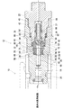
図1は、本発明に係る高圧流体用管継手部材12を示しており、該高圧流体管継手部材は、一点差線で一部を示す液体水素供給用の雌型管継手部材10に連結されて、水素ガスを受け入れるためのものとして示してある。
FIG. 1 shows a high-pressure fluid pipe
すなわち、高圧流体用管継手部材12は、全体として筒状とされ、水素ガスを受け入れる入口側(図1において左側端部開口側)から高圧流体タンクに連結される出口側(右側端部開口側)に延びる流体通路14を有している。具体的には、該高圧流体用管継手本体12は、その主要部品として、第1筒状部材20と、第1筒状部材20に対し、第1筒状部材の出口側開口から挿入されて固定される第2筒状部材22と、弁座部材24と、該弁座部材24を第1及び第2筒状部材20,22の間に固定するための固定部材26と、逆止弁形式の弁部材27を有している。
That is, the high-pressure fluid pipe
第1筒状部材20の内壁面は、入口側から出口側に向けて延びて該流体通路14の上流側部分を画定する流体通路画定面25と、該流体通路画定面25の出口側端縁26から半径方向外側に延びる第1半径方向面28と、該第1半径方向面28の外周縁から当該流体通路14の軸線に対して平行に延びて固定部材26の外周面に接する固定部材設定面30と、該固定部材設定面30よりも大きい径を有し、傾斜面32により固定部材設定面30に接続されている弁座部材設定面34と、該弁座部材設定面34の出口側端縁から半径方向外側に延びる第2半径方向面36と、該第2半径方向面36の外周縁から当該流体通路の軸線に平行に延びるシールリング設定面38と、該シールリング設定面よりも出口側にあり、第2筒状部材22のオネジ面40にネジ係合されるメネジ面42と、を有している。
An inner wall surface of the first
第2筒状部材22は、その先端部分の外周面がシールリング設定面38とほぼ同径とされて、その先端面により、弁座部材24及び固定部材26を第1筒状部材20の第1半径方向面28との間に挟着固定するようになっている。
The second
弁座部材24は、全体として環状とされ、その外周面44が弁座部材設定面34と同径とされて、その上流側部分が該弁座部材設定面34に接するようにされ、下流側部分がシールリング設定面38から間隔をあけて平行に延びるように設定される。該弁座部材24は、外周面44の入口側端縁から半径方向内向きに延びる環状の入口側端面46と、該外周面44の出口側端縁から半径方向内向きに延びる環状の出口側端面48と、入口側端面46と出口側端面48との間で延びる内周面50とを有しており、該内周面50は、当該流体通路の軸線に平行に延びる入口側部分、及び、該入口側部分から後方に向けて広がり出口側端面48まで延びる出口側部分を有し、該入口側部分と出口側部分との間に弁座面52を形成している。
The
固定部材26は、全体として環状とされ、その外周面56のほぼ全体が固定部材設定面30に接するようにされ、同外周面の出口側端部において径が大きくされて弁座部材設定面34に接するようにされている。該固定部材26は断面がほぼ矩形状とされ、その入口側端面58が第1半径方向面28と、出口側端面60が弁座部材24の入口側端面と当接するようになされている。該固定部材の出口側端面60は弁座部材の入口側端面46よりも半径方向寸法が大とされ、該弁座部材の入口側端面46の全体が該固定部材の出口側端面60に当接するようにされている。
The fixing
固定部材26には、その外周面に環状のシールリング嵌合溝64が形成され、該シールリング嵌合溝64に嵌合されたシールリング66が、固定部材設定面30に密封係合されるようになされている。該固定部材26には、該固定部材の外周面と第1筒状部材の内周面との間の微小な隙間に封入される可能性のある圧力を流体通路に逃すためまた、シールリング66を封入された圧力により破損することを防止するための封入圧除去手段が設けられるが、図示の例では、シールリング嵌合溝64より入口側にある該固定部材の入口側端面に形成される溝68と、同嵌合溝64より出口側において該固定部材を半径方向に延びている貫通孔70とにより当該封入圧除去手段が構成されている。
An annular seal
弁座部材24の外周面と、第2半径方向面36と、シールリング設定面38と、第2筒状部材22の先端面によって断面矩形状のシールリング設定空間が画定されており、該シールリング設定空間内にシールリング72が設定されて、該弁座部材24の外周面とシールリング設定面38との間で密封されている。また、該シールリング設定空間内における該シールリング72の入口側及び出口側には、バックアップリング74,76がそれぞれ設定されている。該バックアップリングは、弁座部材24の外周面とシールリング設定面38との間に設定されており、第1及び第2筒状部材の相互接触面間の隙間や、第2筒状部材と弁座部材24の外周面との間の接触面間の隙間にシールリングが食い込むのを防止するためのものである。図示の例では、同様のシールリング78、及び一対のバックアップリング80,82が第1及び第2筒状部材の間に設定されている。
A seal ring setting space having a rectangular cross section is defined by the outer peripheral surface of the
第2筒状部材22の先端部分には、半径方向に延びる連通孔84が設けられている。すなわち、この連通孔84は、当該第2筒状部材の内周面86、すなわち、当該高圧流体用管継手部材の流体通路14における下流部分を画定している面から、第1筒状部材のシールリング設定面38と接触している第2筒状部材の外周面88まで延びており、流体通路の圧力を該連通孔84、及び、第1筒状部材のシールリング設定面38と第2筒状部材22の外周面との間の微小な隙間を通して、シールリング設定空間に通じることができるようにしている。
A
弁部材27は、全体として筒状とされ、その入口側端部90がテーパ状の閉止端とされており、そのテーパ面が図示のように、弁座部材24の内周面に形成された弁座面52と係合可能とされており、また、その筒状側壁にはそれを貫通する貫通孔92が設けられている。該弁部材27は、圧縮バネ94により、弁部材27を入口側に付勢され、入口側端部90のテーパ面が弁座面52に押圧係合されるようになされている。
The
図示の実施形態においては、固定部材26の入口側に筒状のフィルタ96が取り付けられている。すなわち、該フィルタ96は、固定部材から延びる筒状フィルタ部と、その先端の端部金属部とから構成されている。
In the illustrated embodiment, a
高圧流体用管継手部材12に高圧流体供給用の管継手部材10が連結されて、該管継手部材10から高圧流体の供給が始まると、該弁部材27が圧縮バネ94の付勢力に抗して動かされ、弁座面から離れて、流体通路が開かれ流体の供給が行われる。
When the high-pressure fluid pipe
高圧流体の供給の開始瞬間の段階では、弁部材27が開いておらず、このため、流体通路14の弁部材よりも上流側が高圧となり、その圧力は、弁座部材24と固定部材26との当接面の間、弁座部材24と弁座部材設定面34との接触面の間を通りシールリング設定空間にかかる。このため、シールリング72及びバックアップリング74,76が出口側の方へ押圧され変形され、このとき、出口側のバックアップリング76とシールリング設定面との間、出口側のバックアップリング76と弁座部材24の外周面との間に隙間が生じ、シールリング72がそれらの隙間に食い込む可能性がある。
The
しかし、本発明では、第2筒状部材の先端部分に連通孔84が設けられているために、その後に開かれる弁座面よりも下流側に達する高圧流体の圧力が、弁座部材と第2筒状部材の先端面との間の隙間のほかに、第2筒状部材の先端部分外周面とシールリング設定面との間の隙間を通して、シールリング設定用空間に加えられ、上記のようなシールリングの食い込みがあったとしても、それを是正することが出来る。このため、弁部材が閉じられて、供給側の管継手部材が外されたときに、シールリング72は適正な状態でそのシール機能を奏することが可能となり、該シールリング設定空間を通して、流体通路の上流側に高圧流体が漏洩することを防止することができる。
However, in the present invention, since the
以上、本発明の実施形態を説明したが、本発明はこれに限定されるものではない。例えば、本発明に係る高圧流体用管継手部材を雄型管継手部材として示したが、これを雌型管継手部材とすることもできる。 As mentioned above, although embodiment of this invention was described, this invention is not limited to this. For example, although the pipe joint member for high-pressure fluid according to the present invention is shown as a male pipe joint member, it can be a female pipe joint member.
高圧流体用管継手部材12; 水素ガス供給用の雌型管継手部材10; 流体通路14;
第1筒状部材20; 第2筒状部材22; 弁座部材24; 固定部材26;
弁部材27; 流体通路画定面25; 第1半径方向面28; 固定部材設定面30;
傾斜面32; 弁座部材設定面34; 第2半径方向面36;
シールリング設定面38 ;オネジ面40; メネジ面42; 外周面44;
入口側端面46; 出口側端面48; 内周面50; 弁座面52; 外周面56;
出口側端面60; シールリング嵌合溝64; シールリング66; 溝68;
貫通孔70; シールリング72; バックアップリング74,76;
シールリング78; バックアップリング80,82; 連通孔84; 内周面86;
外周面88; 入口側端部90; 貫通孔92; 圧縮バネ94; フィルタ96 ;
High-pressure fluid
First
Seal
Inlet
Outlet
Through-
Outer
Claims (8)
該流体通路内に設定されて該弁座に対して係合・係合解除されて当該流体通路の開閉を行う弁部材と
を有する高圧流体用管継手部材であって、
該高圧流体用管継手本体は、第1筒状部材、及び、該第1筒状部材に対し、該第1筒状部材の該出口側から挿入されて固定される第2筒状部材を有し、
該第1筒状部材の内周面が、該入口側から該出口側に向けて延びて該流体通路の上流部分を画定する流体通路画定面と、該流体通路画定面の出口側端部縁から半径方向外側に延びる第1半径方向面と、該第1半径方向面よりも該出口側にあり該第1半径方向面の外周縁よりも大きい径で該流体通路の軸線に平行に延びる弁座設定面と、該弁座設定面の出口側端部縁から半径方向外側に延びる第2半径方向面と、該第2半径方向面の外周縁から該流体通路の軸線に平行に延びるシールリング設定面と、を有し、
該高圧流体用管継手部材が更に、
該弁座設定面に係合される上流側部分と該シールリング設定面に平行に延びる下流側部分とを有する筒状の外周面と、該外周面の入口側端部縁から半径方向内向きに延びる環状の入口側端面と、該外周面の出口側端縁から半径方向内向きに延びる環状の出口側端面と、該入口側端面及び出口側端面の間を延びる筒状の内周面とを有する弁座部材を有し、
該第2筒状部材が、該第1筒状部材の該シールリング設定面を接するように挿入された外周面を有する先端部分を有し、該先端部分の先端面が、該弁座部材の出口側端面に当接して、該弁座部材を第1筒状部材の第1半径方向面との間で保持するようにされており、
該第2筒状部材の先端面と、該シールリング設定面と、第2半径方向面と、該弁座部材の外周面とによって筒状のシールリング設定空間が形成され、該シールリングが該シールリング設定空間内に設定されて、該弁座部材の外周面及び該シールリング設定面に密封係合するようになされ、
該弁部材は、該弁座部材に係合して該流体通路を閉じるようになされており、
該第2筒状部材の該先端部分が、該流体通路の下流部分を画定している該第2筒状部材の内周面から、該先端部分を半径方向で貫通して、該第1筒状部材のシールリング設定面に接している該先端部分の外周面に至る連通孔を有していることを特徴とする高圧流体用管継手部材。 A tubular high pressure fluid pipe fitting body having a fluid passage extending from an inlet side for receiving high pressure fluid to an outlet side connected to a high pressure fluid tank, and a valve seat provided on the wall surface of the fluid passage so as to surround the fluid passage. When,
A pipe member for high-pressure fluid having a valve member set in the fluid passage and engaged / disengaged from the valve seat to open and close the fluid passage,
The high-pressure fluid pipe fitting main body has a first tubular member and a second tubular member that is inserted and fixed to the first tubular member from the outlet side of the first tubular member. And
An inner peripheral surface of the first tubular member extending from the inlet side toward the outlet side to define an upstream portion of the fluid passage; and an outlet-side end edge of the fluid passage definition surface radius and a first radial surface extending outwardly, said first radius than the direction plane located at the outlet side first radial surface valve extending parallel to the axis of the fluid passage at a greater diameter than the outer peripheral edge of the A seat setting surface, a second radial surface extending radially outward from an outlet-side end edge of the valve seat setting surface, and a seal ring extending parallel to the axis of the fluid passageway from an outer peripheral edge of the second radial surface And a setting surface,
The high pressure fluid pipe joint member further comprises:
A cylindrical outer peripheral surface having an upstream portion engaged with the valve seat setting surface and a downstream portion extending in parallel with the seal ring setting surface, and radially inward from an inlet side end edge of the outer peripheral surface An annular inlet-side end surface extending inward, an annular outlet-side end surface extending radially inward from the outlet-side end edge of the outer peripheral surface, and a cylindrical inner peripheral surface extending between the inlet-side end surface and the outlet-side end surface A valve seat member having
Is the second tubular member having a tip portion with inserted outer peripheral surface so as to contact the seal ring setting surface of the first tubular member, the distal end surface of the tip portion, the valve seat member The valve seat member is held between the first radial surface of the first tubular member,
A cylindrical seal ring setting space is formed by the tip surface of the second cylindrical member, the seal ring setting surface, the second radial surface, and the outer peripheral surface of the valve seat member, and the seal ring is Is set in a seal ring setting space, and is configured to sealingly engage with an outer peripheral surface of the valve seat member and the seal ring setting surface;
The valve member is adapted to engage the valve seat member to close the fluid passage;
The distal end portion of the second tubular member penetrates the distal end portion in a radial direction from the inner peripheral surface of the second tubular member defining the downstream portion of the fluid passage, and the first tube A high-pressure fluid pipe joint member having a communication hole reaching the outer peripheral surface of the tip portion in contact with the seal ring setting surface of the member.
Priority Applications (7)
| Application Number | Priority Date | Filing Date | Title |
|---|---|---|---|
| JP2007075506A JP4895881B2 (en) | 2007-03-22 | 2007-03-22 | Pipe fitting for high pressure fluid |
| KR1020097019782A KR101128754B1 (en) | 2007-03-22 | 2008-03-19 | Pipe joint member for high-pressure fluid |
| CA 2681304 CA2681304C (en) | 2007-03-22 | 2008-03-19 | Pipe coupling member for high-pressure fluid |
| US12/532,565 US8342202B2 (en) | 2007-03-22 | 2008-03-19 | Pipe coupling member for high-pressure fluid |
| CN2008800140387A CN101711323B (en) | 2007-03-22 | 2008-03-19 | Pipe joint member for high-pressure fluid |
| PCT/JP2008/055074 WO2008114816A1 (en) | 2007-03-22 | 2008-03-19 | Pipe joint member for high-pressure fluid |
| EP08722461.4A EP2131091B1 (en) | 2007-03-22 | 2008-03-19 | Pipe joint member for high-pressure fluid |
Applications Claiming Priority (1)
| Application Number | Priority Date | Filing Date | Title |
|---|---|---|---|
| JP2007075506A JP4895881B2 (en) | 2007-03-22 | 2007-03-22 | Pipe fitting for high pressure fluid |
Publications (3)
| Publication Number | Publication Date |
|---|---|
| JP2008232361A JP2008232361A (en) | 2008-10-02 |
| JP2008232361A5 JP2008232361A5 (en) | 2010-04-08 |
| JP4895881B2 true JP4895881B2 (en) | 2012-03-14 |
Family
ID=39765920
Family Applications (1)
| Application Number | Title | Priority Date | Filing Date |
|---|---|---|---|
| JP2007075506A Active JP4895881B2 (en) | 2007-03-22 | 2007-03-22 | Pipe fitting for high pressure fluid |
Country Status (7)
| Country | Link |
|---|---|
| US (1) | US8342202B2 (en) |
| EP (1) | EP2131091B1 (en) |
| JP (1) | JP4895881B2 (en) |
| KR (1) | KR101128754B1 (en) |
| CN (1) | CN101711323B (en) |
| CA (1) | CA2681304C (en) |
| WO (1) | WO2008114816A1 (en) |
Families Citing this family (24)
| Publication number | Priority date | Publication date | Assignee | Title |
|---|---|---|---|---|
| FR2991424B1 (en) * | 2012-05-29 | 2014-07-11 | Staubli Sa Ets | DISCHARGE AND PURGE DEVICE, CONNECTION TIP, AND CONNECTOR COMPRISING SUCH A DEVICE |
| CN102777719A (en) * | 2012-07-11 | 2012-11-14 | 宁波嘉诚液压有限公司 | Backflow-preventing pipe joint |
| CN102913702B (en) * | 2012-09-29 | 2014-08-13 | 中冶京诚工程技术有限公司 | High pressure rotating joint capable of preventing backflowing |
| ITBS20130168A1 (en) * | 2013-11-15 | 2015-05-16 | Omb Saleri S P A | VALVE FOR METHANE IN IMPROVED SELF-TESTING SYSTEMS |
| US9982511B2 (en) | 2014-01-03 | 2018-05-29 | Proserv Operations, Inc. | Dirty fluid pressure regulator and control valve |
| JP6450562B2 (en) * | 2014-10-27 | 2019-01-09 | 株式会社ジェイテクト | Pressure reducing valve |
| US10670155B2 (en) | 2015-10-05 | 2020-06-02 | Proserv Gilmore Valve Llc | Latching poppet valve |
| US10385982B2 (en) * | 2015-11-24 | 2019-08-20 | Proserv Operations, Inc. | Robust in-line valve |
| DE112016005591T5 (en) * | 2015-12-07 | 2018-10-31 | Nitto Kohki Co., Ltd. | Male coupling member |
| CN108291667B (en) | 2015-12-07 | 2019-10-15 | 日东工器株式会社 | Joint member |
| US10487951B2 (en) | 2016-01-22 | 2019-11-26 | Proserv Operations, Inc. | Non-interflow directional control valve |
| US10591076B2 (en) | 2016-09-15 | 2020-03-17 | Proserv Operations, Inc. | Low friction hydraulic circuit control components |
| CN110168271B (en) * | 2016-10-03 | 2021-03-02 | Csir公司 | Coupling device, drive assembly for a coupling device and method for providing a substance |
| JP6559722B2 (en) | 2017-01-26 | 2019-08-14 | 日東工器株式会社 | Check valve |
| US10739796B2 (en) | 2017-09-22 | 2020-08-11 | Proserv Gilmore Valve Llc | Pressure regulator with reconfigurable hydraulic dampening |
| US10633951B2 (en) | 2017-09-22 | 2020-04-28 | Proserv Operations, Inc. | Pressure regulator with user selectable dampening |
| US11022226B2 (en) | 2018-03-20 | 2021-06-01 | Proserv Operations, Inc. | Microfluidic valve |
| US11054050B2 (en) | 2018-08-13 | 2021-07-06 | Proserv Operations Inc. | Valve with press-fit insert |
| US11209096B2 (en) | 2018-11-19 | 2021-12-28 | Proserv Operations, Inc. | Bilateral and throttling directional control valve |
| US11261982B2 (en) | 2019-06-27 | 2022-03-01 | Proserv Gilmore Valve Llc | Pressure relief valve with bi-directional seat |
| US11828370B2 (en) | 2020-01-02 | 2023-11-28 | Proserv Gilmore Valve Llc | Check valve with conforming seat |
| KR102336331B1 (en) * | 2020-07-31 | 2021-12-09 | (주)모토닉 | Receptacle for fuel cell electric vehicle |
| KR102651683B1 (en) * | 2021-05-04 | 2024-03-28 | 남양넥스모 주식회사 | Receptacle check valve for refueling hydrogen |
| WO2024025246A1 (en) * | 2022-07-26 | 2024-02-01 | 남양넥스모 주식회사 | Receptacle for charging hydrogen |
Family Cites Families (11)
| Publication number | Priority date | Publication date | Assignee | Title |
|---|---|---|---|---|
| US4378028A (en) | 1981-04-13 | 1983-03-29 | Swagelok Company | Quick connect coupling |
| US4828296A (en) | 1987-02-09 | 1989-05-09 | Swagelok Quick-Connect Co. | Bulkhead mounting for fluid fittings |
| CN1057590C (en) | 1995-01-06 | 2000-10-18 | 考尔得产品公司 | Low spill high flow quick coupling valve assembly |
| US6082401A (en) | 1995-01-06 | 2000-07-04 | Colder Products Company | Low spill high flow quick coupling valve assembly |
| US6161578A (en) | 1996-10-09 | 2000-12-19 | Colder Products Company | Low spill high flow quick coupling valve assembly |
| DE20110598U1 (en) * | 2001-06-30 | 2002-08-01 | Weh Erwin | connecting nipple |
| DE10257517B4 (en) * | 2002-12-10 | 2007-09-06 | Neoperl Gmbh | backflow preventer |
| JP3999690B2 (en) * | 2003-03-25 | 2007-10-31 | 日東工器株式会社 | Fitting socket |
| US20050126638A1 (en) * | 2003-12-12 | 2005-06-16 | Halliburton Energy Services, Inc. | Check valve sealing arrangement |
| DE502004008314D1 (en) * | 2004-03-16 | 2008-12-04 | Luxembourg Patent Co | Coupling piece, in particular for the refueling of natural gas vehicles |
| CN2826123Y (en) * | 2005-10-10 | 2006-10-11 | 叶春渊 | Flick preventing structure for quick joint |
-
2007
- 2007-03-22 JP JP2007075506A patent/JP4895881B2/en active Active
-
2008
- 2008-03-19 CN CN2008800140387A patent/CN101711323B/en not_active Expired - Fee Related
- 2008-03-19 CA CA 2681304 patent/CA2681304C/en not_active Expired - Fee Related
- 2008-03-19 US US12/532,565 patent/US8342202B2/en active Active
- 2008-03-19 EP EP08722461.4A patent/EP2131091B1/en not_active Not-in-force
- 2008-03-19 KR KR1020097019782A patent/KR101128754B1/en active IP Right Grant
- 2008-03-19 WO PCT/JP2008/055074 patent/WO2008114816A1/en active Application Filing
Also Published As
| Publication number | Publication date |
|---|---|
| CN101711323B (en) | 2011-12-14 |
| CN101711323A (en) | 2010-05-19 |
| CA2681304A1 (en) | 2008-09-25 |
| EP2131091A4 (en) | 2017-08-16 |
| WO2008114816A1 (en) | 2008-09-25 |
| JP2008232361A (en) | 2008-10-02 |
| KR101128754B1 (en) | 2012-04-16 |
| EP2131091B1 (en) | 2019-01-02 |
| EP2131091A1 (en) | 2009-12-09 |
| CA2681304C (en) | 2012-02-07 |
| US8342202B2 (en) | 2013-01-01 |
| US20100108162A1 (en) | 2010-05-06 |
| KR20090125123A (en) | 2009-12-03 |
Similar Documents
| Publication | Publication Date | Title |
|---|---|---|
| JP4895881B2 (en) | Pipe fitting for high pressure fluid | |
| JP2008232361A5 (en) | ||
| TWI718324B (en) | Pipe joint | |
| JP4896070B2 (en) | Female joint member and male joint member | |
| US20120326439A1 (en) | Valve and Other Connections | |
| JP7387199B2 (en) | Fluid piping device | |
| JP2009079636A (en) | Swivel coupling | |
| JP2010078027A5 (en) | ||
| JP2010078027A (en) | Piping joint | |
| KR101756526B1 (en) | Pipe coupling apparatus | |
| CN211259967U (en) | Fuel pipeline quick connector | |
| FR3061771B1 (en) | DEVICE AND METHOD FOR SEALING TESTING | |
| BE1006081A3 (en) | Bypass pipe fitting for thermoplastic. | |
| JP6901281B2 (en) | Fluid connection device | |
| JP2016205432A (en) | Seal device | |
| WO2012066588A1 (en) | Coupler | |
| US7549678B2 (en) | Systems for actuating a pipe connection | |
| US11041566B2 (en) | Seal structure, sealing method, and coupling equipped with said seal structure | |
| CN203413255U (en) | Quick conduit joint | |
| FR3040755A1 (en) | PRESSURIZED FLUID CONNECTION, FAUCET AND BOTTLE COMPRISING SUCH A FITTING | |
| JP4438117B2 (en) | Pipe fitting | |
| KR20180001534U (en) | Pipe coupling apparatus | |
| KR200493227Y1 (en) | Apparatus for cutting off the leakage of gas | |
| CN212107324U (en) | Quick pipeline connector | |
| KR20110092210A (en) | Hub type structure for valve |
Legal Events
| Date | Code | Title | Description |
|---|---|---|---|
| A621 | Written request for application examination |
Free format text: JAPANESE INTERMEDIATE CODE: A621 Effective date: 20091228 |
|
| A521 | Request for written amendment filed |
Free format text: JAPANESE INTERMEDIATE CODE: A821 Effective date: 20091228 |
|
| A521 | Request for written amendment filed |
Free format text: JAPANESE INTERMEDIATE CODE: A523 Effective date: 20100129 |
|
| TRDD | Decision of grant or rejection written | ||
| A01 | Written decision to grant a patent or to grant a registration (utility model) |
Free format text: JAPANESE INTERMEDIATE CODE: A01 Effective date: 20111130 |
|
| A01 | Written decision to grant a patent or to grant a registration (utility model) |
Free format text: JAPANESE INTERMEDIATE CODE: A01 |
|
| A61 | First payment of annual fees (during grant procedure) |
Free format text: JAPANESE INTERMEDIATE CODE: A61 Effective date: 20111220 |
|
| R150 | Certificate of patent or registration of utility model |
Ref document number: 4895881 Country of ref document: JP Free format text: JAPANESE INTERMEDIATE CODE: R150 Free format text: JAPANESE INTERMEDIATE CODE: R150 |
|
| FPAY | Renewal fee payment (event date is renewal date of database) |
Free format text: PAYMENT UNTIL: 20150106 Year of fee payment: 3 |
|
| R250 | Receipt of annual fees |
Free format text: JAPANESE INTERMEDIATE CODE: R250 |
|
| R250 | Receipt of annual fees |
Free format text: JAPANESE INTERMEDIATE CODE: R250 |
|
| R250 | Receipt of annual fees |
Free format text: JAPANESE INTERMEDIATE CODE: R250 |
|
| R250 | Receipt of annual fees |
Free format text: JAPANESE INTERMEDIATE CODE: R250 |
|
| R250 | Receipt of annual fees |
Free format text: JAPANESE INTERMEDIATE CODE: R250 |
|
| R250 | Receipt of annual fees |
Free format text: JAPANESE INTERMEDIATE CODE: R250 |
|
| R250 | Receipt of annual fees |
Free format text: JAPANESE INTERMEDIATE CODE: R250 |
|
| R250 | Receipt of annual fees |
Free format text: JAPANESE INTERMEDIATE CODE: R250 |
|
| R250 | Receipt of annual fees |
Free format text: JAPANESE INTERMEDIATE CODE: R250 |
|
| R250 | Receipt of annual fees |
Free format text: JAPANESE INTERMEDIATE CODE: R250 |