JP4894596B2 - Portable information reader - Google Patents

Portable information reader Download PDF

Info

Publication number
JP4894596B2
JP4894596B2 JP2007109184A JP2007109184A JP4894596B2 JP 4894596 B2 JP4894596 B2 JP 4894596B2 JP 2007109184 A JP2007109184 A JP 2007109184A JP 2007109184 A JP2007109184 A JP 2007109184A JP 4894596 B2 JP4894596 B2 JP 4894596B2
Authority
JP
Japan
Prior art keywords
battery
small
portable information
small battery
claw portion
Prior art date
Legal status (The legal status is an assumption and is not a legal conclusion. Google has not performed a legal analysis and makes no representation as to the accuracy of the status listed.)
Expired - Fee Related
Application number
JP2007109184A
Other languages
Japanese (ja)
Other versions
JP2008269137A (en
Inventor
信幸 藤原
Current Assignee (The listed assignees may be inaccurate. Google has not performed a legal analysis and makes no representation or warranty as to the accuracy of the list.)
Denso Wave Inc
Original Assignee
Denso Wave Inc
Priority date (The priority date is an assumption and is not a legal conclusion. Google has not performed a legal analysis and makes no representation as to the accuracy of the date listed.)
Filing date
Publication date
Application filed by Denso Wave Inc filed Critical Denso Wave Inc
Priority to JP2007109184A priority Critical patent/JP4894596B2/en
Publication of JP2008269137A publication Critical patent/JP2008269137A/en
Application granted granted Critical
Publication of JP4894596B2 publication Critical patent/JP4894596B2/en
Expired - Fee Related legal-status Critical Current
Anticipated expiration legal-status Critical

Links

Images

Description

本発明は、光学情報コード、IDタグに対する読取り機能を備えた電池駆動式の携帯型情報読取装置に関し、特に、2種類の電池を収容可能な携帯型情報読取装置に関するものである。 The present invention relates to a battery-driven portable information reader having a reading function for an optical information code and an ID tag, and more particularly to a portable information reader capable of accommodating two types of batteries.

携帯型情報読取装置は、使用者の利用態様によって、長時間、電池交換無しに利用したい場合と、また、通常のペースで電池交換を行いながら利用できる場合とがある。それぞれの要求に対応するためには、1台の携帯型情報読取装置において、容量の大きな大型電池と、容量の小さな小型電池とのいずれでも収容できるようにすることが望ましい。ここで、特許文献1には、角形二次電池と円筒形単三型電池とのいずれも収容可能な電池収容構造が開示されている。
特開平11−144693号公報
The portable information reader may be used for a long time without battery replacement, or may be used while replacing the battery at a normal pace, depending on the usage mode of the user. In order to meet each request, it is desirable that one portable information reader can accommodate either a large battery with a large capacity or a small battery with a small capacity. Here, Patent Document 1 discloses a battery housing structure that can accommodate both a square secondary battery and a cylindrical AA battery.
Japanese Patent Laid-Open No. 11-144893

しかしながら、図8(A)に示すように、凹部274を有する電池収容部270と凹部281を有する電池蓋280とに大型電池56Lを収容する構造に、図8(B)に示すように小型電池56Sを収容すると、電池蓋280の凹部281に空間が空く。このため、携帯型情報読取装置が落下した際に、小型電池の端子が携帯型情報読取装置側の接続端子から外れて、電力供給が絶えることとなる。 However, as shown in FIG. 8 (A), the large battery 56L is accommodated in the battery accommodating portion 270 having the recess 274 and the battery lid 280 having the recess 281, and the small battery as shown in FIG. 8 (B). When 56S is accommodated, a space is formed in the recess 281 of the battery lid 280. For this reason, when the portable information reader is dropped, the terminal of the small battery is disconnected from the connection terminal on the portable information reader and power supply is cut off.

本発明は、上述した課題を解決するためになされたものであり、その目的とするところは、厚みが異なる大型電池と小型電池とをそれぞれ収容可能な携帯型情報読取装置を提供することにある。 The present invention has been made to solve the above-described problems, and an object of the present invention is to provide a portable information reader capable of accommodating a large battery and a small battery having different thicknesses. .

上記目的を達成するため、請求項1の発明は、筐体60に凹形状の電池収容部70を備え、当該電池収容部70に収容した電池を筐体60に対して着脱自在な電池蓋80により保持させる携帯型情報読取装置10であって、
該電池収容部70は、縦横長が同じで厚みが2倍以上の大型電池56Lを1個、又は、小型電池56Sを1個挿入可能であって、
前記電池蓋80は、小型電池56Sを一個装着可能であって、前記小型電池56Sが前記電池収容部70に1個収容される際に、当該小型電池56Sの上面に当接して当該小型電池を押さえる爪部86aを備え、
該爪部86aは、前記大型電池56Lが前記電池収容部70に収容される際に、該電池収容部70の凹形状の側壁74方向へ退避可能に構成されていることを技術的特徴とする。
In order to achieve the above object, according to the first aspect of the present invention, the housing 60 is provided with the concave battery housing portion 70, and the battery lid 80 detachably attachable to the housing 60 from the battery housed in the battery housing portion 70. A portable information reader 10 held by
The battery housing part 70 can be inserted with one large battery 56L or two small batteries 56S having the same vertical and horizontal length and a thickness of at least twice,
The battery cover 80 can be fitted with one small battery 56S, and when one small battery 56S is accommodated in the battery accommodating portion 70, the small battery 56S comes into contact with the upper surface of the small battery 56S. It has a claw portion 86a to hold down,
The claw portion 86a is configured to be retractable toward the concave side wall 74 of the battery accommodating portion 70 when the large battery 56L is accommodated in the battery accommodating portion 70. .

請求項1の携帯型情報読取装置では、電池蓋が、小型電池の下面が電池収容部の凹形状の底部と対向するように1個収容される際に、当該小型電池の上面に当接して支持する爪部を備えるため、該爪部で押さえて支持することで、電池収容部に小型電池が収容された際にも、小型電池が動くことが無く、例え、携帯型情報読取装置が落下した際にも、小型電池の端子が携帯型情報読取装置側の接続端子から外れて、電力供給が絶えることが無くなる。一方、大型電池が電池収容部に収容される際に、該爪部が該電池収容部の凹形状の側壁方向へ退避するため、厚い大型電池を収容することが可能である。 In the portable information reading device according to claim 1, when one battery cover is accommodated such that the lower surface of the small battery faces the concave bottom of the battery accommodating portion, the battery lid contacts the upper surface of the small battery. Since the supporting claw portion is provided, the small battery does not move even when a small battery is accommodated in the battery accommodating portion by holding and supporting the claw portion. For example, the portable information reader is dropped. In this case, the terminal of the small battery is disconnected from the connection terminal on the portable information reader side, so that the power supply is not cut off. On the other hand, when the large battery is accommodated in the battery accommodating portion, the claw portion is retracted toward the concave side wall of the battery accommodating portion, so that a thick large battery can be accommodated.

請求項2の携帯型情報読取装置では、電池収容部に小型電池が1個、電池蓋に1個収容される際に、電池収容部に収容される1個の小型電池の下面が電池収容部の凹形状の底部と対向し、該小型電池の上面が爪部により押さえられ、電池蓋に装着された小型電池が、上面が電池蓋側に当接され、下面が爪部により当接支持される。即ち、電池蓋に装着された小型電池が、電池蓋側に支持されるので、電池蓋に装着された小型電池を収容した状態で、電池蓋を筐体側へ容易に取り付けることができる。更に、該爪部、撓み片及び電池蓋を一体に成形することが可能であり、製造コストを削減することができる。 According to another aspect of the portable information reader of the present invention, when one small battery is accommodated in the battery accommodating portion and one small battery is accommodated in the battery lid, the lower surface of the one small battery accommodated in the battery accommodating portion is the battery accommodating portion. The upper surface of the small battery is pressed by the claw portion, the small battery mounted on the battery lid is abutted on the battery lid side, and the lower surface is abutted and supported by the claw portion. The That is, since the small battery attached to the battery lid is supported on the battery lid side, the battery lid can be easily attached to the housing side in a state in which the small battery attached to the battery lid is accommodated. Furthermore, the claw portion, the flexure piece, and the battery lid can be integrally formed, and the manufacturing cost can be reduced.

請求項3の携帯型情報読取装置では、爪部が、小型電池の厚み方向の下面と当接する撓み片の先端に形成されているため、当該撓み片が小型電池の側面と当接することで小型電池が移動することが無くなり、電池蓋に装着された小型電池を収容した状態で、電池蓋を筐体側へ容易に取り付けることができる。また、電池蓋を筐体に取り付けた状態で、電池蓋に装着された小型電池が動くことが無くなり、該小型電池と電池蓋との衝突によるがたつきを防ぐことができる。 In the portable information reading device according to claim 3, since the claw portion is formed at the tip of the bending piece that comes into contact with the lower surface in the thickness direction of the small battery, the bending piece comes into contact with the side surface of the small battery, thereby reducing the size. The battery does not move, and the battery lid can be easily attached to the housing in a state where the small battery mounted on the battery lid is accommodated. Further, the small battery attached to the battery lid does not move in a state where the battery lid is attached to the housing, and rattling due to the collision between the small battery and the battery lid can be prevented.

請求項4の携帯型情報読取装置では、小型電池の下面が電池収容部の凹形状の底部と対向するように1個収容される際に、該小型電池の上面に当接して当該小型電池を押さえる第2の爪部が電池収容部に備えられているため、該1個の小型電池を電池蓋が外された状態でも固定することができる。更に、該1個の小型電池を取り外す際には、第2の爪部を支持する撓み片を撓ませることで、容易に取り外しができる。このため、電池取り外し用のリボンを無くすことが可能となる。 According to another aspect of the portable information reader of the present invention, when one small battery is accommodated so that the bottom surface of the small battery faces the concave bottom of the battery accommodating portion, the small battery is brought into contact with the top surface of the small battery. Since the second claw portion to be pressed is provided in the battery housing portion, the one small battery can be fixed even when the battery cover is removed. Furthermore, when removing the one small battery, it can be easily removed by bending the bending piece supporting the second claw portion. For this reason, the ribbon for removing the battery can be eliminated.

請求項5の携帯型情報読取装置では、小型電池の下面が電池収容部の凹形状の底部と対向するように1個収容される際に、付勢部材により付勢されて電池蓋から爪部が突出し当該小型電池の上面に当接して支持するため、電池収容部に小型電池が収容された際にも、小型電池が動くことが無く、例え、携帯型情報読取装置が落下した際にも、小型電池の端子が携帯型情報読取装置側の接続端子から外れて、電力供給が絶えることが無くなる。一方、大型電池が電池収容部に収容される際に、該爪部が電池蓋へ退避するため、厚い大型電池を収容することが可能である。 In the portable information reading device according to claim 5, when one small battery is accommodated so as to face the concave bottom of the battery accommodating portion, the nail portion is energized by the urging member and is moved from the battery lid. Projecting and abutting on and supporting the upper surface of the small battery so that the small battery does not move even when the small battery is accommodated in the battery accommodating portion, for example, even when the portable information reader is dropped. The terminal of the small battery is disconnected from the connection terminal on the portable information reader side, so that the power supply is not cut off. On the other hand, when the large battery is accommodated in the battery accommodating portion, the claw portion is retracted to the battery lid, so that a thick large battery can be accommodated.

請求項6の携帯型情報読取装置では、板状の爪部の側面側に斜面が設けられているため、電池蓋の取り付けの際に、該爪部が大型電池と当接した際の退避が容易になる。 In the portable information reading device according to claim 6, since the inclined surface is provided on the side surface of the plate-like claw portion, when the battery lid is attached, the claw portion is retracted when it comes into contact with the large battery. It becomes easy.

[第1実施形態]
以下、本発明を携帯型情報読取装置に適用した第1実施形態を図1乃至図6を参照して説明する。図1は携帯型情報読取装置10の断面を示している。携帯型情報読取装置10は握り部を兼用する操作部12、例えば液晶からなる表示部14などを備えている。操作部12には、例えば複数のキースイッチ16が設けられ、これらキースイッチ16により、動作内容を指示するようになっている。この操作部12には、キースイッチ16に加えて、読取り開始を指示するためのトリガースイッチ18が設けられている。
[First embodiment]
Hereinafter, a first embodiment in which the present invention is applied to a portable information reader will be described with reference to FIGS. FIG. 1 shows a cross section of the portable information reader 10. The portable information reader 10 includes an operation unit 12 that also serves as a gripping unit, for example, a display unit 14 made of liquid crystal. For example, the operation unit 12 is provided with a plurality of key switches 16, and the operation contents are instructed by these key switches 16. In addition to the key switch 16, the operation unit 12 is provided with a trigger switch 18 for instructing the start of reading.

携帯型情報読取装置10の筐体60内にはプリント配線基板20が固定されており、そのプリント配線基板20の一方の面にキースイッチ16がマトリクス状に搭載されている。また、プリント配線基板20の他方の面には2次元受光センサ32が立設して実装されている。 A printed wiring board 20 is fixed in a housing 60 of the portable information reading apparatus 10, and key switches 16 are mounted in a matrix on one surface of the printed wiring board 20. A two-dimensional light receiving sensor 32 is erected and mounted on the other surface of the printed wiring board 20.

筐体60の前端に形成された開口部60Aには光学系ユニット30が配設されており、筐体60内において光学系ユニット30の光軸上となる位置に反射鏡34が配設されていると共に、反射鏡34により折曲げられた光軸上に2次元受光センサ32が位置している。検出対象物は光学系ユニット30及び反射鏡34を介して2次元受光センサ32に結像されるようになっている。 The optical system unit 30 is disposed in the opening 60A formed at the front end of the housing 60, and the reflecting mirror 34 is disposed in the housing 60 at a position on the optical axis of the optical system unit 30. In addition, the two-dimensional light receiving sensor 32 is positioned on the optical axis bent by the reflecting mirror 34. The detection object is imaged on the two-dimensional light receiving sensor 32 via the optical system unit 30 and the reflecting mirror 34.

開口部60A近傍のプリント配線基板22の中央には孔22aが形成されており、その孔22aの周囲に複数の照明用LED38が搭載されている。また、プリント配線基板22の周縁部に対応して送信アンテナコイル42が配置されている。 A hole 22a is formed in the center of the printed circuit board 22 near the opening 60A, and a plurality of illumination LEDs 38 are mounted around the hole 22a. A transmitting antenna coil 42 is disposed corresponding to the peripheral edge of the printed wiring board 22.

プリント配線基板22に形成された孔22aにはレンズユニット36が装着されている。このレンズユニット36は、検出対象物からの反射光を集光する集光レンズ36aと、照明用LED38からの光を正面に投光するための投光レンズ36bとを一体にして形成されている。一方、プリント配線基板22の裏面には受信アンテナコイル44が配置されている。 A lens unit 36 is mounted in the hole 22 a formed in the printed wiring board 22. The lens unit 36 is integrally formed with a condenser lens 36a that condenses the reflected light from the detection target and a light projection lens 36b that projects the light from the illumination LED 38 to the front. . On the other hand, a receiving antenna coil 44 is disposed on the back surface of the printed wiring board 22.

図2は携帯型情報読取装置10の電気的構成を示している。マイクロコンピュータ(以下、マイコン)50は、トリガースイッチ18が操作されたことに応じて照明用LED38の点灯を制御すると共に、2次元受光センサ32からの画像信号を検出するようになっている。また、マイコン50は、送信アンテナコイル42に電力信号を出力すると共に、受信アンテナコイル44が受信したIDタグからの受信信号を抽出するようになっている。 FIG. 2 shows an electrical configuration of the portable information reader 10. A microcomputer (hereinafter referred to as a microcomputer) 50 controls lighting of the illumination LED 38 in response to the operation of the trigger switch 18 and detects an image signal from the two-dimensional light receiving sensor 32. Further, the microcomputer 50 outputs a power signal to the transmission antenna coil 42 and extracts a reception signal from the ID tag received by the reception antenna coil 44.

ここで、マイコン50は、IDタグと通信を行うときは、自動同調回路52により送信アンテナコイル42とコンデンサによって共振回路を構成するが、その共振周波数を送信周波数とほぼ同一となるように自動的に共振回路のコンデンサ容量を制御するようになっている。また、マイコン50は、発音部54を駆動することにより使用者に読取り終了を報知するようになっている。 Here, when the microcomputer 50 communicates with the ID tag, the automatic tuning circuit 52 forms a resonance circuit with the transmission antenna coil 42 and the capacitor, and the resonance frequency is automatically set to be substantially the same as the transmission frequency. The capacitor capacity of the resonance circuit is controlled. In addition, the microcomputer 50 informs the user of the end of reading by driving the sound generation unit 54.

第1実施形態の携帯型情報読取装置10は、図1(A)に示すように小型電池56Sを2個収容することと(この際、1個を電源として接続、他の1個は交換用)、図1(B)に示すように小型電池56Sを1個収容することと、図1(C)に示すように大型電池56Lを1個収容することとができる。ここで、小型電池56Sと大型電池56Lとは、縦横長が同じで、厚みが2倍強異なる。 As shown in FIG. 1A, the portable information reader 10 of the first embodiment accommodates two small batteries 56S (in this case, one is connected as a power source, the other one is for replacement). ), One small battery 56S can be accommodated as shown in FIG. 1B, and one large battery 56L can be accommodated as shown in FIG. 1C. Here, the small battery 56 </ b> S and the large battery 56 </ b> L have the same length and width and are slightly different in thickness.

この収容構造について、図3〜図6を参照して説明する。
図3(A)は、図1(A)中に示す小型電池56Sを2個収容した携帯型情報読取装置10を下側から見た底面図であり、図3(B)は、図3(A)のb−b断面図であり、図3(C)は、図3(A)のc−c断面図であり、図3(D)は、図3(C)に示す携帯型情報読取装置から電池蓋を外した状態を示す断面図である。図4(A)は、小型電池56Sを収容した状態の電池蓋の側面図であり、図4(B)は、図4(A)の電池蓋の底面図である。図4(C)は、小型電池56Sを収容しない状態の電池蓋の側面図であり、図4(D)は、図4(C)の電池蓋の底面図である。図5(A)は、図1(C)中の大型電池56Lを収容した携帯型情報読取装置10を下側から見た底面図であり、図5(B)は、図5(A)のb2−b2断面図であり、図5(C)は、図5(A)のc2−c2断面図である。図5(D)は小型電池56Sが一個収容された状態の断面図である。図6(A)は、図3(B)に示す小型電池56Sを2個収容した携帯型情報読取装置のa1−a1断面図であり、図6(B)は、b1−b1断面図である。図6(C)は、小型電池56Sを1個収容した状態の断面図である。図6(D)は、図5(B)に示す大型電池56Lを1個収容した携帯型情報読取装置のd1−d1断面図であり、図6(E)は、e1−e1断面図である。
This housing structure will be described with reference to FIGS.
FIG. 3A is a bottom view of the portable information reader 10 containing two small batteries 56S shown in FIG. 1A as viewed from below, and FIG. 3A is a cross-sectional view taken along line bb in FIG. 3C, FIG. 3C is a cross-sectional view taken along line cc in FIG. 3A, and FIG. 3D is a portable information reading device shown in FIG. It is sectional drawing which shows the state which removed the battery cover from the apparatus. 4A is a side view of the battery lid in a state where the small battery 56S is accommodated, and FIG. 4B is a bottom view of the battery lid of FIG. 4A. 4C is a side view of the battery lid in a state where the small battery 56S is not accommodated, and FIG. 4D is a bottom view of the battery lid of FIG. 4C. FIG. 5A is a bottom view of the portable information reader 10 containing the large battery 56L in FIG. 1C as viewed from below, and FIG. 5B is a view of FIG. It is b2-b2 sectional drawing, FIG.5 (C) is c2-c2 sectional drawing of FIG. 5 (A). FIG. 5D is a cross-sectional view of a state where one small battery 56S is accommodated. 6A is a cross-sectional view taken along line a1-a1 of the portable information reading apparatus that accommodates two small batteries 56S shown in FIG. 3B, and FIG. 6B is a cross-sectional view taken along line b1-b1. . FIG. 6C is a cross-sectional view of a state where one small battery 56S is accommodated. 6D is a d1-d1 cross-sectional view of a portable information reading apparatus that accommodates one large battery 56L shown in FIG. 5B, and FIG. 6E is an e1-e1 cross-sectional view. .

図3(A)及び図3(B)に示すように、筐体60には、凹形状の電池収容部70が形成され、該筐体60には、着脱可能な電池蓋80が取り付けられる。図3(B)は、図1に対して上下反転させて表示されており、以降の説明では、電池蓋80側を上側、電池収容部70側を下側として参照する。電池蓋80の縦方向後端側(以降、縦方向とは携帯型情報読取装置の長手方向を意味し、縦方向先端側とは開口部60A側を、縦方向後端側とは先端側の反対側を意味する)には、係合片82が形成され、縦方向先端側には鍵状の鍵部材84が形成されている。該係合片82を筐体の係合孔60aに嵌入し、鍵部材84にロック部材62の先端を係合させることで、電池蓋80が筐体60に取り付けられる。ロック部材62は、ロックノブ62aにより図中で矢印Y方向にスライドされることで、鍵部材84にロック部材62の先端が係合、係合解除され、ロック、アンロックが成される。 As shown in FIGS. 3A and 3B, a concave battery housing portion 70 is formed in the casing 60, and a detachable battery lid 80 is attached to the casing 60. 3B is displayed upside down with respect to FIG. 1. In the following description, the battery lid 80 side is referred to as the upper side, and the battery housing portion 70 side is referred to as the lower side. The rear end side in the vertical direction of the battery cover 80 (hereinafter, the vertical direction means the longitudinal direction of the portable information reader, the front end side in the vertical direction is the opening 60A side, and the rear end side in the vertical direction is the front end side. An engagement piece 82 is formed on the opposite side), and a key-shaped key member 84 is formed on the longitudinal tip side. The battery lid 80 is attached to the housing 60 by fitting the engagement piece 82 into the engagement hole 60 a of the housing and engaging the key member 84 with the tip of the lock member 62. The lock member 62 is slid in the direction of the arrow Y in the figure by the lock knob 62a, whereby the tip of the lock member 62 is engaged and disengaged from the key member 84, and locked and unlocked.

凹形状の電池収容部70は、側壁74と底部76とからなり、底部76は収容される小型電池56S、又は、大型電池56Lの下面と対向する。底部76の上面には、緩衝用のクッション材79が設けられている。側壁74は、図3(D)に示すように縦方向先端側及び後端側は、垂直壁に形成されている。一方、図3(B)のa1−a1断面図である図6(A)に示すように横方向(以降、横方向とは携帯型情報読取装置の短手方向を意味する)の側壁74は、断面クランク状に形成され、該横方向の側壁74の底部76側の部位は、小型電池56S、大型電池56Lの側面と当接する幅に形成され、該小型電池56S、大型電池56Lを収容できるようになっている。側壁74の上方は、側方に幅が広がり、小型電池56S、大型電池56Lに対してクリアランスを持たせ交換を容易にしている。図3(D)に示すように、該電池収容部70の縦方向先端側には、小型電池56S、大型電池56Lの端子と接続するための接続端子72が設けられる。縦方向後端側に、収容された小型電池56Sを保持するための第2の爪78が形成されている。該第2の爪78は、下面が小型電池56Sの上面と当接する第2の爪部78aと、該第2の爪部78aを保持し、縦方向後端側の側壁74方向に撓む撓み片78bとからなる。 The concave battery housing portion 70 includes a side wall 74 and a bottom portion 76, and the bottom portion 76 faces the lower surface of the small battery 56S or the large battery 56L to be housed. A cushioning cushion 79 is provided on the upper surface of the bottom 76. As shown in FIG. 3D, the side wall 74 is formed into a vertical wall on the front end side and the rear end side in the vertical direction. On the other hand, as shown in FIG. 6A, which is an a1-a1 cross-sectional view of FIG. 3B, the side wall 74 in the lateral direction (hereinafter, the lateral direction means the lateral direction of the portable information reader) The portion of the lateral side wall 74 on the bottom 76 side is formed in a width that contacts the side surfaces of the small battery 56S and the large battery 56L, and can accommodate the small battery 56S and the large battery 56L. It is like that. The upper side of the side wall 74 is widened to the side, and a clearance is provided for the small battery 56S and the large battery 56L to facilitate replacement. As shown in FIG. 3D, a connection terminal 72 for connecting to the terminals of the small battery 56S and the large battery 56L is provided on the longitudinal end side of the battery housing portion 70. A second claw 78 for holding the accommodated small battery 56S is formed on the rear end side in the vertical direction. The second claw 78 holds the second claw portion 78a whose lower surface is in contact with the upper surface of the small battery 56S, and the second claw portion 78a, and is bent in the direction of the side wall 74 on the rear end side in the vertical direction. It consists of a piece 78b.

第1実施形態の携帯型情報読取装置10では、小型電池56Sの下面が電池収容部70の底部76と対向するように1個収容される際に、該小型電池56Sの上面に当接して当該小型電池56Sを押さえる第2の爪部78aが電池収容部70に備えられているため、該1個の小型電池56Sを電池蓋80が外された状態でも固定することができる。更に、該1個の小型電池56Sを取り外す際には、第2の爪部78aを支持する撓み片78bを撓ませることで、容易に取り外しができる。このため、電池取り外し用のリボンを無くすことが可能となる。 In the portable information reader 10 of the first embodiment, when one small battery 56S is accommodated so that the lower surface of the small battery 56S faces the bottom 76 of the battery accommodating part 70, the small battery 56S comes into contact with the upper surface of the small battery 56S. Since the second claw portion 78a for holding the small battery 56S is provided in the battery housing portion 70, the single small battery 56S can be fixed even when the battery cover 80 is removed. Further, when removing the single small battery 56S, it can be easily removed by bending the bending piece 78b supporting the second claw portion 78a. For this reason, the ribbon for removing the battery can be eliminated.

電池蓋80は、図4(B)に示すように小型電池56Sの縦方向後端側を保持する保持板88と、該電池蓋80に収容される小型電池56Sを保持する2対の爪86とを備える。図6(A)に断面を示すL字形状の爪86は、先端側の爪部86aと該爪部86aを支持する撓み片86bから成る。該撓み片86bは、該電池蓋80に保持される小型電池56Sの側面に当接する。一方、図6(D)に示すように大型電池56Lが収容される際には、撓み片86bは、爪部78aを電池収容部の横方向の側壁74側に退避させるように撓む。図6(A)に示すように爪部86aの上面は、該保持される小型電池56Sの下面に当接し、該爪部86aの下面は、電池収容部70に収容された小型電池56Sの上面に当接する。図4(A)に示すように電池蓋80は、小型電池56Sを保持した状態でも、図4(C)に示すように小型電池56Sを保持しない状態でも筐体60に対して取り付け可能であり、電池蓋80が小型電池56を保持しない状態では、図5(D)に示すように爪部86aの下面は、電池収容部70に収容された小型電池56Sの上面に当接し、該小型電池56Sを電池収容部70に固定させる。一方、図6(D)に示すように、電池収容部70に大型電池56Lが収容されている際には、撓み片86bが横方向の側壁74側に撓むことで、爪部78aが側壁74側に退避し、当該大型電池56Lが収容される際にも、電池蓋80を筐体60に取り付け可能にしている。 As shown in FIG. 4B, the battery cover 80 includes a holding plate 88 that holds the rear end side in the vertical direction of the small battery 56S, and two pairs of claws 86 that hold the small battery 56S accommodated in the battery cover 80. With. The L-shaped claw 86 whose cross section is shown in FIG. 6 (A) includes a claw portion 86a on the distal end side and a bending piece 86b that supports the claw portion 86a. The flexible piece 86b contacts the side surface of the small battery 56S held by the battery lid 80. On the other hand, as shown in FIG. 6D, when the large battery 56L is accommodated, the bending piece 86b bends so as to retract the claw portion 78a toward the side wall 74 in the lateral direction of the battery accommodating portion. As shown in FIG. 6A, the upper surface of the claw portion 86a abuts on the lower surface of the small battery 56S to be held, and the lower surface of the claw portion 86a is the upper surface of the small battery 56S housed in the battery housing portion 70. Abut. As shown in FIG. 4 (A), the battery lid 80 can be attached to the housing 60 even when the small battery 56S is held or when the small battery 56S is not held as shown in FIG. 4 (C). When the battery cover 80 does not hold the small battery 56, the lower surface of the claw portion 86a contacts the upper surface of the small battery 56S accommodated in the battery accommodating portion 70 as shown in FIG. 56S is fixed to the battery accommodating part 70. FIG. On the other hand, as shown in FIG. 6 (D), when the large battery 56L is accommodated in the battery accommodating portion 70, the claw portion 78a becomes the side wall because the bending piece 86b is bent toward the side wall 74 in the lateral direction. The battery cover 80 can be attached to the housing 60 even when retracted to the 74 side and the large battery 56L is accommodated.

第1実施形態の携帯型情報読取装置10では、電池蓋80が、小型電池56Sの下面が電池収容部70の凹形状の底部76と対向するように1個収容される際に、当該小型電池56Sの上面に当接して支持する爪部86aを備えるため、該爪部86aで押さえて支持することで、電池収容部70に小型電池56Sが収容された際にも、小型電池56Sが動くことが無く、例え、携帯型情報読取装置10が落下した際にも、小型電池56Sの端子が携帯型情報読取装置側の接続端子72から外れて、電力供給が絶えることが無くなる。一方、大型電池56Lが電池収容部70に収容される際に、該爪部86aが該電池収容部70の凹形状の側壁74方向へ退避するため、厚い大型電池56Lを収容することが可能である。 In the portable information reading device 10 of the first embodiment, when one battery lid 80 is accommodated so that the lower surface of the small battery 56S faces the concave bottom 76 of the battery accommodating portion 70, the small battery 56 Since the claw portion 86a is provided to contact and support the upper surface of the 56S, the small battery 56S moves even when the small battery 56S is accommodated in the battery accommodating portion 70 by being supported by the claw portion 86a. For example, even when the portable information reader 10 is dropped, the terminal of the small battery 56S is disconnected from the connection terminal 72 on the portable information reader side, and the power supply is not cut off. On the other hand, when the large battery 56L is accommodated in the battery accommodating portion 70, the claw portion 86a is retracted toward the concave side wall 74 of the battery accommodating portion 70, so that the thick large battery 56L can be accommodated. is there.

また、第1実施形態の携帯型情報読取装置10では、電池収容部70に小型電池56Sが1個、電池蓋80に1個収容される際に、電池収容部70に収容される1個の小型電池56Sの下面が電池収容部70の凹形状の底部76と対向し、該小型電池56Sの上面が爪部86aにより押さえられ、電池蓋80に装着された小型電池56Sが、上面が電池蓋80側に当接され、下面が爪部86aにより当接支持される。即ち、電池蓋80に装着された小型電池56Sが、電池蓋80側に支持されるので、電池蓋80に装着された小型電池56Sを収容した状態で、電池蓋80を筐体60側へ容易に取り付けることができる。更に、該爪部86a及び撓み片86bから成る爪86を電池蓋80と一体に成形することで、製造コストを削減できる。 Further, in the portable information reading device 10 of the first embodiment, when one small battery 56S is accommodated in the battery accommodating portion 70 and one is accommodated in the battery lid 80, one small amount is accommodated in the battery accommodating portion 70. The lower surface of the small battery 56S faces the concave bottom 76 of the battery housing portion 70, the upper surface of the small battery 56S is pressed by the claw portion 86a, and the small battery 56S attached to the battery lid 80 has the upper surface of the battery lid. The lower surface is abutted and supported by the claw portion 86a. In other words, since the small battery 56S attached to the battery lid 80 is supported on the battery lid 80 side, the battery lid 80 can be easily moved to the housing 60 side in a state where the small battery 56S attached to the battery lid 80 is accommodated. Can be attached to. Furthermore, the manufacturing cost can be reduced by forming the claw 86 including the claw portion 86a and the bending piece 86b integrally with the battery lid 80.

更に、第1実施形態の携帯型情報読取装置10では、爪部86aが、小型電池56Sの厚み方向の下面と当接する撓み片86bの先端に形成されているため、当該撓み片86bが小型電池56Sの側面と当接することで小型電池56Sが移動することが無くなり、電池蓋80に装着された小型電池56Sを収容した状態で、電池蓋80を筐体60側へ容易に取り付けることができる。また、電池蓋80を筐体60に取り付けた状態で、電池蓋80に装着された小型電池56Sが動くことが無くなり、該小型電池56Sと電池蓋80との衝突によるがたつきを防ぐことができる。 Furthermore, in the portable information reading device 10 of the first embodiment, the claw portion 86a is formed at the tip of the bending piece 86b that contacts the lower surface in the thickness direction of the small battery 56S, so the bending piece 86b is the small battery. The small battery 56S does not move by coming into contact with the side surface of the 56S, and the battery cover 80 can be easily attached to the housing 60 side while the small battery 56S attached to the battery cover 80 is accommodated. Further, the small battery 56S attached to the battery lid 80 does not move in a state where the battery lid 80 is attached to the housing 60, and rattling due to the collision between the small battery 56S and the battery lid 80 can be prevented. it can.

[第2実施形態]
引き続き、本発明の第2実施形態に係る携帯型情報読取装置について、図7を参照して説明する。
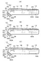
図7(A)は、第2実施形態の携帯型情報読取装置の電池収容部に小型電池56Sが収容された際の説明図であり、図7(B)は、図7(A)のb3−b3断面に対応する説明図であり、図7(A)は、図7(B)中のa3−a3断面に対応する。図7(C)は、電池収容部に大型電池56Lが収容された際の説明図であり、図7(D)は、図7(C)のd3−d3断面に対応する説明図であり、図7(C)は、図7(D)中のc3−c3断面に対応する。図7(E)及び図7(F)は、電池収容部に大型電池56Lが収容された際の電池蓋80の取り付けの説明図であり、図7(F)は、図7(E)中のf3−f3断面に対応する。
[Second Embodiment]
Next, a portable information reading apparatus according to the second embodiment of the present invention will be described with reference to FIG.
FIG. 7A is an explanatory diagram when the small battery 56S is accommodated in the battery accommodating portion of the portable information reading device of the second embodiment, and FIG. 7B is b3 in FIG. 7A. It is explanatory drawing corresponding to -b3 cross section, and FIG. 7 (A) respond | corresponds to the a3-a3 cross section in FIG. 7 (B). FIG. 7C is an explanatory diagram when the large battery 56L is accommodated in the battery accommodating portion, and FIG. 7D is an explanatory diagram corresponding to the d3-d3 cross section of FIG. FIG. 7C corresponds to a c3-c3 cross section in FIG. FIGS. 7E and 7F are explanatory views of attachment of the battery lid 80 when the large battery 56L is accommodated in the battery accommodating portion, and FIG. 7F is a view in FIG. Corresponds to the f3-f3 cross section.

上述した第1実施形態では、爪部86aで小型電池56Sを保持し、大型電池56Lが収容される際には、撓み片86bが撓むことで爪部86aを側方へ退避させた。これに対して、第2実施形態で、図7(B)に示すように、板状の爪部96により、小型電池56Sを保持し、図7(D)に示すように大型電池56Lが収容される際には、付勢部材を構成するバネ94によって、電池蓋180側に板状の爪部96が退避する。バネ94は、支持部材92に支持されている。支持部材92は、電池蓋180に設けられた溝孔186に取り付けられる。 In 1st Embodiment mentioned above, the small battery 56S was hold | maintained by the nail | claw part 86a, and when the large battery 56L was accommodated, the nail | claw part 86a was retracted to the side because the bending piece 86b bent. In contrast, in the second embodiment, the small battery 56S is held by the plate-like claw portion 96 as shown in FIG. 7B, and the large battery 56L is accommodated as shown in FIG. 7D. In doing so, the plate-like claw 96 is retracted to the battery lid 180 side by the spring 94 constituting the biasing member. The spring 94 is supported by the support member 92. The support member 92 is attached to a slot 186 provided in the battery lid 180.

即ち、図7(B)に示すように、電池蓋180の凹部184に小型電池56Sが収容された状態で、板状の爪部96は、電池蓋180から突出し、該板状の爪部96の上面(図7(B)中の右側)が該小型電池56Sの下面に当接して支持する。電池収容部170の凹部174に小型電池56Sが収容され、小型電池56Sの端子が電池収容部170の接続端子172に接続された状態で、該小型電池56Sの上面が板状の爪部96の下面に当接して支持される。 That is, as shown in FIG. 7B, in the state where the small battery 56S is accommodated in the recess 184 of the battery lid 180, the plate-like claw portion 96 protrudes from the battery lid 180, and the plate-like claw portion 96. The upper surface (the right side in FIG. 7B) contacts and supports the lower surface of the small battery 56S. The small battery 56S is housed in the recess 174 of the battery housing 170, and the terminal of the small battery 56S is connected to the connection terminal 172 of the battery housing 170, and the upper surface of the small battery 56S is the plate-like claw 96. It is supported by contacting the lower surface.

一方、図7(C)、図7(D)に示すように、電池収容部170の凹部174及び電池蓋180の凹部184に大型電池56Lが収容された状態では、バネ94によって、電池蓋180内に板状の爪部96が退避する。 On the other hand, as shown in FIGS. 7C and 7D, when the large battery 56L is housed in the recess 174 of the battery housing 170 and the recess 184 of the battery lid 180, the battery lid 180 is moved by the spring 94. The plate-like claw portion 96 is retracted inside.

第2実施形態の携帯型情報読取装置では、小型電池56Sの下面が電池収容部170の凹部174の底部と対向するように1個収容される際に、バネ94により付勢されて電池蓋180から爪部96が突出し当該小型電池56Sの上面に当接して支持するため、電池収容部170に小型電池56Sが収容された際にも、小型電池56Sが動くことが無く、例え、携帯型情報読取装置が落下した際にも、小型電池56Sの端子が携帯型情報読取装置側の接続端子172から外れて、電力供給が絶えることが無くなる。一方、大型電池56Lが電池収容部170に収容される際に、該爪部96が電池蓋180へ退避するため、厚い大型電池56Lを収容することが可能である。 In the portable information reading apparatus of the second embodiment, when one small battery 56S is accommodated so that the lower surface of the small battery 56S faces the bottom of the recess 174 of the battery accommodating part 170, the battery lid 180 is urged by the spring 94. Since the claw portion 96 protrudes from and contacts and supports the upper surface of the small battery 56S, even when the small battery 56S is accommodated in the battery accommodating portion 170, the small battery 56S does not move. Even when the reading device falls, the terminal of the small battery 56S is disconnected from the connection terminal 172 on the portable information reading device side, so that the power supply is not cut off. On the other hand, when the large battery 56L is accommodated in the battery accommodating portion 170, the claw portion 96 is retracted to the battery lid 180, so that the thick large battery 56L can be accommodated.

図7(E)、図7(F)に示すように、板状の爪部96は4角形に形成され、バネ94の付勢方向に対する側面側(縦方向後端側)の斜面96aが形成されている。板状の爪部96の側面側に斜面96aが設けられているため、電池蓋180の取り付けの際に、該爪部96が大型電池56Lと当接した際の退避が容易になる。 As shown in FIGS. 7E and 7F, the plate-like claw portion 96 is formed in a quadrangular shape, and a slope 96a on the side surface (vertical rear end side) with respect to the biasing direction of the spring 94 is formed. Has been. Since the inclined surface 96a is provided on the side surface of the plate-like claw portion 96, when the battery lid 180 is attached, the claw portion 96 is easily retracted when it comes into contact with the large battery 56L.

上述した実施形態では、携帯型情報読取装置として、光学情報コード、IDタグの両方が読み取り可能な携帯型情報読取装置を例示したが、本発明の電池収容構造は、光学情報コード、IDタグの一方のみの読み取り用の携帯型情報読取装置に適用できることは言うまでもない。 In the above-described embodiment, the portable information reader is exemplified as a portable information reader that can read both the optical information code and the ID tag. However, the battery housing structure of the present invention includes the optical information code and the ID tag. Needless to say, the present invention can be applied to only one portable information reader for reading.

本発明の第1実施形態に係る携帯型情報読取装置の断面図である。It is sectional drawing of the portable information reader which concerns on 1st Embodiment of this invention. 第1実施形態の携帯型情報読取装置の電気的構成を示すブロック図である。It is a block diagram which shows the electric constitution of the portable information reader of 1st Embodiment. 図3(A)は、図1(A)中に示す小型電池を2個収容した携帯型情報読取装置を下側から見た底面図であり、図3(B)は、図3(A)のb−b断面図であり、図3(C)は、図3(A)のc−c断面図であり、図3(D)は、図3(C)に示す携帯型情報読取装置から電池蓋を外した状態を示す断面図である。FIG. 3A is a bottom view of the portable information reading apparatus containing two small batteries shown in FIG. 1A as viewed from below, and FIG. 3B is a view of FIG. 3C is a cross-sectional view taken along the line cc of FIG. 3A, and FIG. 3D is a plan view of the portable information reader shown in FIG. It is sectional drawing which shows the state which removed the battery cover. 図4(A)は、小型電池を収容した状態の電池蓋の側面図であり、図4(B)は、図4(A)の電池蓋の底面図である。図4(C)は、小型電池を収容しない状態の電池蓋の側面図であり、図4(D)は、図4(C)の電池蓋の底面図である。4A is a side view of the battery lid in a state where a small battery is accommodated, and FIG. 4B is a bottom view of the battery lid of FIG. 4A. 4C is a side view of the battery lid in a state where the small battery is not accommodated, and FIG. 4D is a bottom view of the battery lid of FIG. 4C. 図5(A)は、図1(C)中の大型電池を収容した携帯型情報読取装置を下側から見た底面図であり、図5(B)は、図5(A)のb2−b2断面図であり、図5(C)は、図5(A)のc2−c2断面図である。図5(D)は小型電池が一個収容された状態の断面図である。FIG. 5A is a bottom view of the portable information reading apparatus that accommodates the large battery in FIG. 1C as viewed from below, and FIG. 5B is b2- in FIG. 5A. It is b2 sectional drawing, FIG.5 (C) is c2-c2 sectional drawing of FIG. 5 (A). FIG. 5D is a cross-sectional view of a state where one small battery is accommodated. 図6(A)は、図3(B)に示す小型電池を2個収容した携帯型情報読取装置のa1−a1断面図であり、図6(B)は、b1−b1断面図である。図6(C)は、小型電池を1個収容した状態の断面図である。図6(D)は、図5(B)に示す大型電池を1個収容した携帯型情報読取装置のd1−d1断面図であり、図6(E)は、e1−e1断面図である。6A is a cross-sectional view taken along line a1-a1 of the portable information reading apparatus containing two small batteries shown in FIG. 3B, and FIG. 6B is a cross-sectional view taken along line b1-b1. FIG. 6C is a cross-sectional view of a state where one small battery is accommodated. 6D is a cross-sectional view taken along d1-d1 of the portable information reading apparatus in which one large battery shown in FIG. 5B is accommodated, and FIG. 6E is a cross-sectional view taken along e1-e1. 図7(A)は、第2実施形態の携帯型情報読取装置の電池収容部に小型電池が収容された際の説明図であり、図7(B)は、図7(A)のb3−b3断面に対応する説明図である。図7(C)は、電池収容部に大型電池が収容された際の説明図であり、図7(D)は、図7(C)のd3−d3断面に対応する説明図である。図7(E)及び図7(F)は、電池収容部に大型電池が収容された際の電池蓋の取り付けの説明図である。FIG. 7A is an explanatory diagram when a small battery is accommodated in the battery accommodating portion of the portable information reading device of the second embodiment, and FIG. 7B is a b3- in FIG. 7A. It is explanatory drawing corresponding to a b3 cross section. FIG. 7C is an explanatory diagram when a large battery is accommodated in the battery accommodating portion, and FIG. 7D is an explanatory diagram corresponding to the d3-d3 cross section of FIG. 7C. FIGS. 7E and 7F are explanatory diagrams of attachment of a battery lid when a large battery is accommodated in the battery accommodating portion. 先行技術の電池収容構造の説明図である。It is explanatory drawing of the battery accommodation structure of a prior art.

符号の説明Explanation of symbols

10 携帯型情報読取装置
60 筐体
70 電池収容部
74 側壁
76 底部
78a 爪部
78b 撓み片
80 電池蓋
86a 爪部
86b 撓み片
94 バネ(付勢部材)
96 板状の爪部
170 電池収容部
180 電池蓋
DESCRIPTION OF SYMBOLS 10 Portable information reader 60 Case 70 Battery accommodating part 74 Side wall 76 Bottom part 78a Claw part 78b Deflection piece 80 Battery cover 86a Claw part 86b Deflection piece 94 Spring (biasing member)
96 Plate-shaped claw part 170 Battery accommodating part 180 Battery cover

Claims (6)

筐体に凹形状の電池収容部を備え、当該電池収容部に収容した電池を筐体に対して着脱自在な電池蓋により保持させる携帯型情報読取装置であって、
該電池収容部は、縦横長が同じで厚みが2倍以上の大型電池を1個、又は、小型電池を1個挿入可能であって、
前記電池蓋は、小型電池を一個装着可能であって、前記小型電池が前記電池収容部に1個収容される際に、当該小型電池の上面に当接して当該小型電池を押さえる爪部を備え、 該爪部は、前記大型電池が前記電池収容部に収容される際に、該電池収容部の凹形状の側壁方向へ退避可能に構成されていることを特徴とする携帯型情報読取装置。
A portable information reading device comprising a housing with a concave battery housing, and holding the battery housed in the battery housing with a battery lid that is detachable from the housing,
The battery housing portion can be inserted one large battery having the same vertical and horizontal length and a thickness of twice or more, or one small battery,
The battery lid can be equipped with one small battery, and includes a claw portion that comes into contact with an upper surface of the small battery and holds the small battery when the small battery is accommodated in the battery accommodating portion. The claw portion is configured to be retractable toward the concave side wall of the battery housing portion when the large battery is housed in the battery housing portion.
前記電池収容部に前記小型電池が1個収容され、前記電池蓋に前記小型電池が1個装着される際に、
前記電池収容部に収容される小型電池の下面が前記電池収容部の凹形状の底部と対向し、該小型電池の上面が前記爪部により押さえられ、
前記電池蓋に装着される前記小型電池が、上面が前記電池蓋側に当接され、下面が前記爪部により当接支持されることを特徴とする請求項1の携帯型情報読取装置。
When one small battery is accommodated in the battery accommodating portion and one small battery is attached to the battery lid,
The lower surface of the small battery housed in the battery housing portion faces the concave bottom of the battery housing portion, and the upper surface of the small battery is pressed by the claw portion,
2. The portable information reader according to claim 1, wherein the small battery mounted on the battery lid has an upper surface abutted on the battery lid side and a lower surface abutted and supported by the claw portion.
前記爪部が、前記電池蓋に装着される前記小型電池の厚み方向の下面と当接する位置に、電池収容部の側壁方向へ撓み可能な撓み片の先端に形成されていることを特徴とする請求項2の携帯型情報読取装置。 The claw portion is formed at the tip of a bending piece that can be bent in the side wall direction of the battery housing portion at a position that contacts the lower surface in the thickness direction of the small battery attached to the battery lid. The portable information reader according to claim 2. 前記電池収容部は、前記小型電池が1個収容される際に、該小型電池の上面に当接して該小型電池を押さえる第2の爪部を備え、該第2の爪部が、前記1個の小型電池の上面と当接すると共に、電池収容部の凹形状の側壁方向へ撓み可能な撓み片に形成されていることを特徴とする請求項3の携帯型情報読取装置。 The battery accommodating portion includes a second claw portion that contacts the upper surface of the small battery and holds the small battery when the small battery is accommodated, and the second claw portion includes the first claw portion. 4. The portable information reading device according to claim 3, wherein the portable information reading device is formed in a bending piece that is in contact with the upper surface of each small battery and can be bent toward the concave side wall of the battery housing portion. 前記爪部が、板状に形成され、付勢部材によって前記電池蓋から突出可能であると共に、電池蓋側に退避可能に形成されていることを特徴とする請求項1又は請求項2の携帯型情報読取装置。 The mobile phone according to claim 1 or 2, wherein the claw portion is formed in a plate shape, can be protruded from the battery lid by an urging member, and can be retracted to the battery lid side. Type information reader. 前記板状の爪部が、4角形に形成され、前記付勢部材の付勢方向に対する側面側に、斜面が設けられていることを特徴とする請求項5の携帯型情報読取装置。 6. The portable information reader according to claim 5, wherein the plate-like claw portion is formed in a quadrangular shape, and an inclined surface is provided on a side surface side with respect to the urging direction of the urging member.
JP2007109184A 2007-04-18 2007-04-18 Portable information reader Expired - Fee Related JP4894596B2 (en)

Priority Applications (1)

Application Number Priority Date Filing Date Title
JP2007109184A JP4894596B2 (en) 2007-04-18 2007-04-18 Portable information reader

Applications Claiming Priority (1)

Application Number Priority Date Filing Date Title
JP2007109184A JP4894596B2 (en) 2007-04-18 2007-04-18 Portable information reader

Publications (2)

Publication Number Publication Date
JP2008269137A JP2008269137A (en) 2008-11-06
JP4894596B2 true JP4894596B2 (en) 2012-03-14

Family

ID=40048578

Family Applications (1)

Application Number Title Priority Date Filing Date
JP2007109184A Expired - Fee Related JP4894596B2 (en) 2007-04-18 2007-04-18 Portable information reader

Country Status (1)

Country Link
JP (1) JP4894596B2 (en)

Family Cites Families (2)

* Cited by examiner, † Cited by third party
Publication number Priority date Publication date Assignee Title
JPH0353748A (en) * 1989-07-21 1991-03-07 Nec Corp Voice storage device
JP3910507B2 (en) * 2002-08-19 2007-04-25 富士フイルム株式会社 Electronics

Also Published As

Publication number Publication date
JP2008269137A (en) 2008-11-06

Similar Documents

Publication Publication Date Title
US6244894B1 (en) Cellular phone battery equipped with IC card
KR101082209B1 (en) Battery device and electronic apparatus
US20050062478A1 (en) Power supply unit for electronic devices
KR101122943B1 (en) Battery device and electronic apparatus
JP7010579B2 (en) Connection unit, information processing device
JP2011060626A (en) Switch device
JP2012136192A (en) In-vehicle electronic device
WO2008075869A1 (en) Bar code reader
JP2011204508A (en) Switch device
US20160064874A1 (en) Board connection structure and electronic device
JP4894596B2 (en) Portable information reader
JP6819069B2 (en) Image forming device
CN116018476A (en) Reader/writer device and holder for reader/writer
JPH04272882A (en) Printer device
US7396235B2 (en) Modular electronic device
JP3896228B2 (en) Bar code reader attachment and portable information terminal
JP2000348133A (en) Reader/writer for tag
JP3923624B2 (en) IC card reader
JP2004220504A (en) Bar code handy terminal
US20210218187A1 (en) Connector and connection adapter
JP2000242423A (en) Cordless mouse
JP2017107504A (en) Information read device
JP4154247B2 (en) Barcode handy terminal
JP2021112001A (en) Battery and portable terminal
CN115114942A (en) Information reading assembly, information reading device and expansion module

Legal Events

Date Code Title Description
A621 Written request for application examination

Free format text: JAPANESE INTERMEDIATE CODE: A621

Effective date: 20090825

A977 Report on retrieval

Free format text: JAPANESE INTERMEDIATE CODE: A971007

Effective date: 20111124

TRDD Decision of grant or rejection written
A01 Written decision to grant a patent or to grant a registration (utility model)

Free format text: JAPANESE INTERMEDIATE CODE: A01

Effective date: 20111129

A01 Written decision to grant a patent or to grant a registration (utility model)

Free format text: JAPANESE INTERMEDIATE CODE: A01

A61 First payment of annual fees (during grant procedure)

Free format text: JAPANESE INTERMEDIATE CODE: A61

Effective date: 20111212

R150 Certificate of patent or registration of utility model

Ref document number: 4894596

Country of ref document: JP

Free format text: JAPANESE INTERMEDIATE CODE: R150

Free format text: JAPANESE INTERMEDIATE CODE: R150

FPAY Renewal fee payment (event date is renewal date of database)

Free format text: PAYMENT UNTIL: 20150106

Year of fee payment: 3

FPAY Renewal fee payment (event date is renewal date of database)

Free format text: PAYMENT UNTIL: 20150106

Year of fee payment: 3

R250 Receipt of annual fees

Free format text: JAPANESE INTERMEDIATE CODE: R250

R250 Receipt of annual fees

Free format text: JAPANESE INTERMEDIATE CODE: R250

R250 Receipt of annual fees

Free format text: JAPANESE INTERMEDIATE CODE: R250

R250 Receipt of annual fees

Free format text: JAPANESE INTERMEDIATE CODE: R250

R250 Receipt of annual fees

Free format text: JAPANESE INTERMEDIATE CODE: R250

R250 Receipt of annual fees

Free format text: JAPANESE INTERMEDIATE CODE: R250

LAPS Cancellation because of no payment of annual fees