JP4891258B2 - Fin mounting mechanism - Google Patents
Fin mounting mechanism Download PDFInfo
- Publication number
- JP4891258B2 JP4891258B2 JP2007546230A JP2007546230A JP4891258B2 JP 4891258 B2 JP4891258 B2 JP 4891258B2 JP 2007546230 A JP2007546230 A JP 2007546230A JP 2007546230 A JP2007546230 A JP 2007546230A JP 4891258 B2 JP4891258 B2 JP 4891258B2
- Authority
- JP
- Japan
- Prior art keywords
- fin
- main body
- surfboard
- box
- fin box
- Prior art date
- Legal status (The legal status is an assumption and is not a legal conclusion. Google has not performed a legal analysis and makes no representation as to the accuracy of the status listed.)
- Expired - Fee Related
Links
Images


Classifications
-
- B—PERFORMING OPERATIONS; TRANSPORTING
- B63—SHIPS OR OTHER WATERBORNE VESSELS; RELATED EQUIPMENT
- B63B—SHIPS OR OTHER WATERBORNE VESSELS; EQUIPMENT FOR SHIPPING
- B63B32/00—Water sports boards; Accessories therefor
- B63B32/60—Board appendages, e.g. fins, hydrofoils or centre boards
- B63B32/66—Arrangements for fixation to the board, e.g. fin boxes or foil boxes
Landscapes
- Chemical & Material Sciences (AREA)
- Engineering & Computer Science (AREA)
- Combustion & Propulsion (AREA)
- Mechanical Engineering (AREA)
- Ocean & Marine Engineering (AREA)
- Connection Of Plates (AREA)
- Vehicle Step Arrangements And Article Storage (AREA)
Description
本発明は、水上や水中を進むための小型の乗り物や器具(small water craft)に用いるフィン及びその取付け部材に関する。特には、サーフボードに種々の形状のフィンを取付ける機構に関する。 The present invention relates to a fin used for a small vehicle or a small water craft for traveling on or under water, and a mounting member for the fin. In particular, the present invention relates to a mechanism for attaching fins of various shapes to a surfboard.
多くのスポーツ器具と同様、ユーザーの嗜好や使用時の条件に合った製品を仕立てて用意すべく、基本品に対する種々の変形品が開発されている。サーフボードの後部下面にフィンが取付けられたものについてもそうである。 As with many sports equipment, various modifications to the basic product have been developed to tailor and prepare products that meet user preferences and usage conditions. This is also the case with fins attached to the rear lower surface of the surfboard.
サーフボードの持ち主にとり、自分の体重や波乗りのスタイルに最も合ったフィンを探す目的で試して見るためにも、また、時々折々波乗りを行う条件に合わせるためにも、フィンを取替え可能とすることは明らかに有利である。 For surfboard owners, it is possible to change fins for the purpose of trying to find a fin that best suits your weight and surfing style, and to meet the conditions of occasional surfing. Clearly advantageous.
取替え可能なフィンシステムは、公知であり、いわゆるフィンボックスに保持されるフィンを選択することからなる。具体例は、米国特許US 5, 830, 025及びUS 5, 975, 974、及び国際特許公開WO 01/70565に見られる。フィンボックスは、一般に、サーフボードの製造中にサーフボードの本体に作り込まれた永続的な取付け具であり、また、一般に、フィンのタブまたは付け根を差し込むスロットを含んでいる。差し込まれたフィンを固定して保持する手段としては、比較的単純なスナップ留め機構から、フィンボックスへのフィンの取付けに、道具をあてがう必要のある止め具を組み込んだ構成まで、多種多様のものがある。
これらのシステムの不利な点は、フィンボックスが一つの形状のフィンタブを受け入れるために設計されていることである。そのため、サーフボードの持ち主は、自分のサーフボードのメーカー以外のメーカーからの種々のフィンに取り替えたり試して見たいと思っても、または、少なくとも自分のサーフボードに嵌め込まれたフィンボックスのメーカー以外のメーカーからの種々のフィンに取り替えたり試して見たいと思っても、選択の範囲が制限される。 The disadvantage of these systems is that the fin box is designed to accept a single shaped fin tab. So surfboard owners want to try and replace with various fins from manufacturers other than their own surfboard manufacturer, or at least from manufacturers other than the manufacturer of the fin box that fits into their surfboard Even if you want to replace or try out different fins, your selection is limited.
本発明の目的は、このような不利な点のいくつかについて、手立てを行うか、または少なくとも改善することである。 The object of the present invention is to address or at least improve some of these disadvantages.
一の態様において、本発明は、サーフボードなどの本体に対して取り外し可能にフィンを取付ける取付け構造である。ここで、フィンにはこれに組み合わされたフィンタブが備えられ、該取付け構造は、前記サーフボード中に差し込まれて保持されるのに適したものとなっており、また、複数の形状のフィンタブを受け入れて取り外し可能に保持するのに適したもので、これにより、前記フィンを、前記サーフボードに対して固定した位置関係にて取り外し可能に保持することができる。 In one aspect, the present invention is a mounting structure for removably attaching a fin to a body such as a surfboard. Here, the fin is provided with a fin tab combined therewith, and the mounting structure is suitable for being inserted and held in the surfboard and accepts a plurality of fin tabs. The fins can be detachably held in a fixed positional relationship with respect to the surfboard.
別の態様によると、本発明は、サーフボードにおける少なくとも一つのフィンのための複数の形状のフィンタブを取り外し可能に取付ける方法であって、(a)前記サーフボード中に、少なくとも中央のフィンボックス(細長い本体及び凹陥部からなるフィンボックス)を嵌め込んだものを用意する工程と、(b)前記フィンボックス中における傾斜付きネジ切孔に備えられた止めネジ(set screw)を、前記フィンタブの差込を可能にするのに充分なまでに後退させる工程と、(c)前記止めネジを前記フィンタブに接触させるようにねじ込む工程と、からなる。 According to another aspect, the present invention is a method for removably attaching a plurality of shaped fin tabs for at least one fin in a surfboard, comprising: (a) at least a central fin box (elongate body) in the surfboard. And a step (b) in which a fin screw comprising a recessed portion is fitted, and (b) a set screw provided in a slanted screw hole in the fin box is inserted into the fin tab. Retracting enough to allow, and (c) screwing the set screw into contact with the fin tab.
別の態様によると、本発明は、サーフボードなどの本体に対して取り外し可能にフィンを取付けるフィンボックスである。ここで、フィンにはこれに組み合わされたフィンタブが備えられ、該フィンボックスは、前記サーフボード中に差し込まれて保持されるのに適したものとなっており、また、複数の形状のフィンタブを受け入れて取り外し可能に保持するのに適したもので、これにより、前記フィンを、前記サーフボードに対して固定した位置関係にて取り外し可能に保持することができる。ここで、さらには、前記フィンボックスの第1面についての長さ及び幅が、前記フィンの全体を支えるのに充分であって、前記フィンのいずれの部分もサーフボード等の本体に接触しない。 According to another aspect, the present invention is a fin box for removably attaching a fin to a body such as a surfboard. Here, the fin is provided with a fin tab combined therewith, and the fin box is suitable for being inserted and held in the surfboard, and accepts fin tabs of a plurality of shapes. The fins can be detachably held in a fixed positional relationship with respect to the surfboard. Here, furthermore, the length and width of the first surface of the fin box are sufficient to support the entire fin, and none of the fins contact the main body such as a surfboard.
別の態様によると、本発明は、水上や水中を進むための小型の乗り物や器具の中に配置されるのに適したフィン保持機構であって、(1)互いに異なる形状のフィンタブを有する複数の互いに異なるタイプのフィンを受け入れるような寸法の開口を取り囲み、前記乗り物や器具の外面を突き抜けるように装着される本体と、(2)本体の前記開口を取り囲み、該開口から外側へと延びるフランジであって、前記本体が前記乗り物や器具中に配置された際には、該乗り物や器具の外面とほぼ面一(つらいち)となる(すなわち、周囲の面との間で段差を生じず、連続した面をなす)ように配置されるフランジと、(3)前記本体中に配置されて第1の形状のフィンタブに係合す第1の保持機構と、(4)前記本体中に配置されて第2の形状のフィンタブに係合す第2の保持機構とを備える。 According to another aspect, the present invention is a fin holding mechanism suitable for being placed in a small vehicle or equipment for traveling on or under water, and (1) a plurality of fin tabs having differently shaped fin tabs. A body that surrounds an opening sized to receive different types of fins, and is mounted to penetrate the outer surface of the vehicle or instrument, and (2) a flange that surrounds the opening of the body and extends outward from the opening When the main body is disposed in the vehicle or appliance, the main body is substantially flush with the outer surface of the vehicle or appliance (that is, there is no step between the surrounding surfaces). A flange arranged to form a continuous surface), (3) a first holding mechanism disposed in the body and engaging a first-shaped fin tab, and (4) disposed in the body. Engaged with the second shaped fin tab And a second retaining mechanism.
本発明の実施形態について添付の図面を参照して説明する。 Embodiments of the present invention will be described with reference to the accompanying drawings.
<第1の好ましい実施形態>
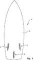
本発明の第1の好ましい実施形態では、図1〜2を参照すると、サーフボード10に3つのフィン保持構造体12,13及び14が嵌めこまれている。これらは、一般にフィンボックスと呼ばれており、サーフボード10の下面16に挿嵌されている。フィンボックス12は、センターフィン17用であり、フィンボックス13及び14は、左側フィン18及び右側フィン19をそれぞれ受け入れる。
<First Preferred Embodiment>
In a first preferred embodiment of the present invention, referring to FIGS. 1-2, three
フィン17,18及び19は、フィン保持構造体であるフィンボックス12,13及び14中に、フィンの上端エッジに設けられたフィンタブによって保持されている。フィンの上端エッジは、サーフボード10の下面16と、実質上、面一(つらいち)である。市販の典型的なフィン及びフィンタブの例を、図3に示す。
The
再度、図2を参照するならば、次のことが知られる。センターフィン17の中央平面は、サーフボード10の下面16と垂直であり、左右のフィン18及び19は、該中央平面に対して左右に傾斜している。傾斜角度は、一般に、5度である。外側フィンの傾斜角は、左右のフィンボックス13及び14の凹陥部の傾斜角によっても、また、フィンタブに対するフィンの傾斜角によっても設けることができる。本発明のフィンボックス13及び14は、フィンとタブが一直線上にある(すなわち、フィンタブにはフィンに対する傾斜角が付けられていない)外側フィン13及び14に対して傾斜角を与えるものであり、なおかつ、フィンタブとの間に傾斜角が付けられた外側フィンをも用いることができるようにする。以下、詳細に説明する。
Again referring to FIG. 2, the following is known. The center plane of the
まず、一の好ましい形態における特定の構造のフィンボックスであって、中央及び外側のフィンとして、まっすぐに延びるフィンタブまたは傾斜したフィンタブを有する複数種の市販のフィンを用いることができるものについて説明する。図4を参照すると、中央のフィンボックス20は、凹陥部24を有する全体に細長の本体22からなる。本体22は、図1及び図5に示すように、フィンボックス20がサーフボードの本体に取り付けられた際に、通常、サーフボード10の下面16と面一(つらいち)である。第1面25は、本体22から外側へと延びる外周フランジ26を含んでいる。
First, a fin box having a specific structure in one preferred embodiment, in which a plurality of types of commercially available fins having straight extending fin tabs or inclined fin tabs can be used as the central and outer fins, will be described. Referring to FIG. 4, the
凹陥部24は、本体中へと、図3の市販のフィンのフィンタブについて、いずれをも受け入れるのに充分な深さにまで達している。図4及び5から最も良く知られるように、本体22には、さらに、左右両側のいずれにも、一対のバットレス部(支持・補強用の傾斜した突き出し壁部)28が設けられている。各バットレス部28は、フランジ26の上面から延びて、面31のエッジへと向かってすぼまるテーパー状をなしている。傾斜付きネジ切孔34A及び34Bが、凹陥部24の左右両側に設けられており、図5,6及び7から最も良く知られるように、平面25から凹陥部の内面へと突き抜けている。他の傾斜付きネジ切孔35は、凹陥部24の前方端の内壁面へと突き抜けている。図4及び7から知られるように垂直ネジ切孔37も設けられている。
The
凹陥部24の幅及び形状は、図3の各フィンタブを差し込むことのできるようなものとなっている。そのため、例えば、主たる凹陥部24から外側へと突き出す横方向凹陥部23は、図3Aのフィンにおけるフィンタブ29の突出部30を受け入れるのに適したものとなっている。図9から知ることができるように、図3Aのフィンタブ29は、止めネジ38によって、フィンボックス20の凹陥部24に確実に固定されて保持される。止めネジ38は、凹陥部24の左右一方の側にある傾斜付きネジ切孔34A中へとねじ込まれて、フィンタブ29の円柱状部分40に係合する。
The width and shape of the
図6及び7を参照するならば、凹陥部24に保持部材32が備えられている。保持部材32は、凹陥部24の後方端の内壁面から突き出して凹陥部24の幅方向全体にわたって延びている。保持部材32は、図3Cのフィンタブ34における後方ノッチ35に係合するのに適したものとなっている。図10に示すように、図3Cのフィンタブ34は、後方でノッチ35が保持部材32に係合し、前方で止めネジ38が前方ノッチ37に係合することにより、フィンボックス20中に保持される。また、図10には示さないが、止めネジ38を、フィンタブ34の側面へと、傾斜付きネジ切孔34A及び34Bを突き抜けるようにねじ込むことができる。
Referring to FIGS. 6 and 7, the
図3Bのフィンは、2つの部分42A及び42Bからなるフィンタブを有している。本実施形態のフィンボックスにフィンタブを収納するためには、図8に示す差込具44Aが備えられる。差込具44Aは、図3Cのフィンタブ34と同様の外形寸法を有し、同様の後方ノッチ45及び前方ノッチ46を備える。差込具44Aが、フィンボックス中20にて、保持部材32と、前方ネジ切孔35を突き抜ける止めネジ38とによって保持されるようになっているのである。差込具44Aは、また、抜き部48A及び48Bを有し、これらが、フィンタブの2つの部分42A及び42Bを受け入れる寸法に設けらている。これらフィンタブ部分42A及び42Bは、止めネジが、傾斜付きネジ切孔34A及び34Bを突き抜けるようにねじ込まれて、フィンタブ部分42A及び42Bの側面へと押し付けられることによって、フィンボックス20中に固定される。
The fin of FIG. 3B has a fin tab consisting of two
図15及び16を参照すると、図3Dのフィンは、フィンタブ50が、フィンとフィンタブとの接合面にスロット51を備える。このフィンは、フィンボックスの凹陥部24に差し込まれた際、スロット51中に差し込まれたプレート53によって保持される。ここで、該プレート53は、垂直ネジ切孔237にネジ52によってねじ止めされて、フィンボックスに固定される。
Referring to FIGS. 15 and 16, in the fin of FIG. 3D, the
左右のフィンボックス13及び14は、以上に説明した中央のフィンボックス20と同様の形状を有するが、凹陥部は多少変更されている。左右のフィンボックス13及び14は、対称となる形状構成を有するため、左側フィンボックスについてのみ詳細に説明する。
The left and
図11Aには、3フィン・サーフボードの左側フィンのためのフィンボックス13の平面図を示す。このフィンボックスの凹陥部124は、凹陥部の内壁面におけるサーフボードの外縁(図11Aにおける左側)に最も近い部分128が、図11BのA-A断面図及びD-D断面図に示すように、5度だけ傾斜している。主たる凹陥部124から外側へと延びる横方向凹陥部123では、互いに向き合う内壁面123A及び123Bが、C-C断面図から知られるように、主たる凹陥部124の傾斜面部分128に平行となるように、サーフボードの外縁(図11Aにおける左側)に向かって傾斜している。
FIG. 11A shows a plan view of the
外側への傾斜面部分128は、A-A断面及びD-D断面の箇所にて、主たる凹陥部124の範囲内に位置しており、図11Cに示すような直線配列フィンタブや、図11Dに示すような傾斜付きフィンタブを有するところの、本発明のフィンボックスに受け入れ可能なフィン構成を受け入れるようになっている。左右のフィンにおいて、図3A及び図3Bのフィンタブは、直線配列状であり、図3Cのフィン及び図3Dのフィンは、左右に5度傾斜している。
The outwardly
図11A及び図11Bにおける外側への傾斜面部分128の配置から知られるように、図3Aのフィンの直線状フィンタブ29は、凹陥部124に差し込まれた際に、外側へと5度傾斜する。両側壁面が5度の傾斜角を有するA-A断面部、B-B断面部及びC-C断面部中にて、直線状フィンタブ29は、全ての垂直面でもって滑るようにして差し込まれるからである。
As is known from the outwardly
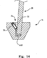
同様に、図3Bの構成のフィンタブは、前述したと同様、図13の差込具44Bと組み合わされて、B-B断面部及びD-D断面部に装着される。しかし、図13の差込具44Bには、5度の傾斜が抜き部48C及び48Dに作り込まれている。図14に示すように、図3Bのフィンが差込具44Bとともに凹陥部24中に配置され、傾斜付きネジ切孔135を突き抜ける止めネジ38によって位置が固定されている。
Similarly, the fin tab having the configuration of FIG. 3B is mounted on the BB cross section and the DD cross section in combination with the
ところが、図3Cのフィンタブ34、及び図3Dのフィンタブ50は、5度の傾斜を付けずに、フィンボックス中に保持する必要がある。このことは、凹陥部124の残りの部分126、すなわち垂直の平行な内壁面を有する部分によって実現できる。
However, the
また、フィンボックス13には、一対の傾斜付きネジ切孔134A及び134Bが、凹陥部124における、サーフボードの外縁から遠い側(図11Aの右側)にだけ設けられる。そのため、図3Aのフィンの直線配列フィンタブは、孔134Aを突き抜けてねじ込まれる止めネジによって、フィンボックス中、所望の傾斜位置へと押し込まれ、また、傾斜した内壁面に、サーフボードの外側へとむかって、押し付けられる。
Also, the
図13及び14を参照すると、図3Bの直線配列フィンタブ42A及び42Bは、差込具44Bの抜き部48C及び48Dに差し込むことによって5度の傾斜が付けられる。この後、フィンタブは、抜き部48C及び48Dのスロット50を突き抜ける止めネジ38によって、抜き部48C及び48D中にて固定され、フィンタブが、凹陥部24における外側へと傾斜した面に押し付けられる。このようにして、フィンが、サーフボードの外縁に向かって5度の傾斜を付けられる。
Referring to FIGS. 13 and 14, the linear
図3Cのフィンタブ34、及び、図3Dのフィンタブ50は、中央のフィンボックスについて前述したと同様の、通常の、垂直の向きの配置にて保持される。
The
本発明に置ける中央及び左右のフィンボックスは、また、調整可能なフィンを受け入れて保持することができる。図12に示すように、調整可能なフィン210は、より短いフィンタブ212を備える。好ましくは、このフィンタブ212は、凹陥部224よりも20mm短く、フィン210が中央の位置から前後へと10mmだけ動くことができる。フィンタブ210は、さらに、ノッチ235を備え、フィンタブが、後方壁233に押し付けられるまでの範囲に配置できるようになっており、最も後方の位置に配置された際にも保持部材(32;図6及び7中)の妨げを受けないようになっている。ところが、フィンタブ212は、保持部材の凹陥部224にも、また、傾斜付きネジ切孔235中の止めネジ235にも頼らずに保持されている。
The center and left and right fin boxes in the present invention can also receive and hold adjustable fins. As shown in FIG. 12, the adjustable fin 210 includes a shorter fin tab 212. Preferably, the fin tab 212 is 20 mm shorter than the recess 224 so that the fin 210 can move 10 mm back and forth from the central position. The fin tab 210 further includes a
本実施形態において、フィン210のフィンタブ212には、凹陥部214A及び214Bが設けられている。図12に示すような左側のフィンボックス、または右側のフィンボックスにおいて、2つの凹陥部が、フィンタブの左右一方の側にある。すなわち、傾斜付きネジ切孔234が位置する側にある。中央のフィンでは、このような凹陥部が、タブの左右両側に設けられており、中央のフィンボックスに互いに同等の傾斜付きネジ切孔が前述したように設けられていることに対応している。凹陥部214の長さは、傾斜付きネジ切孔234にねじ込まれた止めネジ241が、ユーザーの好みの位置に関わらず、凹陥部に係合できるようなものとなっている。
In the present embodiment, the fin tab 212 of the fin 210 is provided with recessed portions 214A and 214B. In the left-side fin box or the right-side fin box as shown in FIG. 12, the two recessed portions are on the left and right sides of the fin tab. That is, it is on the side where the inclined threaded
<第2の好ましい実施形態>
本発明の他の好ましい実施形態においては、フィンボックスが、図6〜8及び図11及び12に示された前述のものよりも、いくらかシンプルになっている。本実施形態において、左右及び中央のフィンボックスは、図3B及び図3Cの形状構成のフィンタブ付きのフィンを装着するためのものである。
<Second Preferred Embodiment>
In another preferred embodiment of the invention, the fin box is somewhat simpler than the one shown in FIGS. 6-8 and FIGS. In the present embodiment, the left and right and center fin boxes are for mounting fins with fin tabs having the configuration shown in FIGS. 3B and 3C.
図17を参照すると、中央のフィンボックス300、右側フィンボックス302及び左側フィンボックス304は、いずれも、上記のように、中央の凹陥部308及び外周フランジ301を備えた細長い本体306からなる。図17中に破線で示すように、また、図18から最も良く知られるように、本実施形態における凹陥部308は、後方端内壁面311から突き出した保持構造319を備える。
Referring to FIG. 17, the
第1の外面316は、凹陥部308の周りの、外周フランジ310の第1の内側部分からなる。フランジ310の外側部分318は、第1の外面316を除いた残りの領域である。図17、17A、17B及び17Cから知られるように、第1の外面316と、フランジ310の外側部分318との間のオフセット印刷版と印刷領域との間のような関係は、フィンボックスがサーフボードの本体に装着された際に、外側部分318の面が、サーフボードの発泡体コア307と面一(つらいち)となり、第1の外面316が、下面322における製品完成後のガラス繊維外皮320の表面322と面一(つらいち)となるようにするものである。
The first
第1の外面316がサーフボードの表面322と面一(つらいち)であるものの、第1の外面316の幅及び長さは、フィンボックス300,302または304に装着されたフィンのいずれの部分も、サーフボードの下面322に接触しないようなものとなっている。フィンのブレード部は、このようにして、第1の外面316の領域内にて第1の外面316により充分に支持される。
Although the first
図17、17A、17B及び17Cを参照するならば、本実施形態における右側フィンボックス302及び左側フィンボックス304は、いずれも、2つの外側への傾斜壁面部309を有する。右側及び左側のフィンボックス302及び304における外側への傾斜壁面部309は、それぞれ、サーフボードの右側及び左側へと傾斜している。傾斜壁面部309の長さ及び配置は、図3の「B」のフィンタブ構成における前後のフィンタブ42A及び42Bの長さ及び間隔に一致している。各傾斜壁面部309と向かい合う側、すなわち左右方向逆側には、傾斜付きネジ切孔313が、第1の外面316から、これに隣接する、凹陥部308の側壁面へと突き抜けるように備えられる。
Referring to FIGS. 17, 17A, 17B, and 17C, the
図17、17A、17B及び17Cに示すように、右側及び左側フィンボックス302及び304は、本実施形態において、それぞれ、右側の取り外し可能な差込具330、及び、左側の取り外し可能な差込具332を備える。取り外し可能な差込具330及び332の幅及び深さ寸法は、凹陥部308をほぼ満たす寸法となっている。図18B及び18Cを参照するならば、取り外し可能な差込具330及び332は、いずれも差込具の後方端にノッチ334を有しており、凹陥部308の保持構造319に対して、取り外し可能に係合するのに適したものとなっている。
As shown in FIGS. 17, 17A, 17B and 17C, the right and left
取り外し可能な差込具330及び332は、いずれも、一対の受け入れ凹陥部(それぞれ331及び333)をも有している。受け入れ凹陥部331及び333の長さ及び配置は、差込具330及び332が、それぞれ右側及び左側のフィンボックス300及び302に差し込まれた際に、受け入れ凹陥部が傾斜壁面部309の長さ及び配置に一致するようになっている。受け入れ凹陥部331及び333の内壁面336には、スロット338が設けられており、傾斜付きネジ切孔313を突き抜けるようにねじ込まれた取付けネジ339が、該スロット338を通り抜けて前後2部分構成のフィンタブに係合する。
Both
受け入れ凹陥部331及び333の内壁面336は、傾斜壁面部309の傾斜と同じだけ傾斜しており、差込具が凹陥部308中に配置された際には、傾斜壁面部309と、受け入れ凹陥部331及び333の内壁面336とが平行となる。このように平行配置される一対の面の間隔は、図3の2部分構成フィンタブ42A及び42Bの厚みに一致する。
The
図17B及び図17Cの断面図から知られるように、これら2部分構成フィンタブがフィン342の中央面340から直線状に延びることから、これらフィン342は、サーフボードの下面322に対して外側への傾斜角を付けられている。そのため、2部分構成フィンタブ付きのフィンは、取り外し可能な差込具330を嵌め込んだ右側フィンボックス300に差し込まれた状態にて、サーフボードの右側へと傾斜する。同じフィンが、同様に、左側フィンボックス302及びこれに組み合わされた差込具332に差し込まれた際には、サーフボードの左側へと傾斜する。
As known from the cross-sectional views of FIGS. 17B and 17C, these two-part fin tabs extend linearly from the
図17A及び17Cを参照するならば、中央のフィンボックス300の凹陥部308には傾斜壁面部が設けられておらず、向かい合う左右側部の内壁面が、平行であってサーフボードの下面322に対して垂直である。中央のフィンボックス300には、また、2つの傾斜付ネジ切孔317が設けられており、これらは、左右のフィンボックスに置ける傾斜付ネジ切孔313と同様に、凹陥部の長さ方向に沿って、間隔を置いて配列されている。但し、一つずつ、凹陥部308の左右に配置されている。
Referring to FIGS. 17A and 17C, the recessed
中央のフィンボックス300には、図18Aに示した取り外し可能な差込具350が設けられている。この差込具350は、左右のフィンボックスに差し込まれる前述の差込具330及び332と同様の外形及び寸法を有する。この取り外し可能な差込具350にも受け入れ凹陥部352が設けられており、これら受け入れ凹陥部352は、長さ方向に沿った寸法及び配置が、右側及び左側の差込具における受け入れ凹陥部331及び333と同様である。但し、受け入れ凹陥部352は、向かって奥側の壁面354が傾斜しておらず、差込具350が凹陥部308に差し込まれた際、面同士が平行の、垂直に配置されたスロット状の凹陥部をなす。
The
そのため、2部分構成フィンタブ付きのフィンは、取り外し可能な差込具350を備えた中央のフィンボックス300に装着されたならば、サーフボードの下面322に対して垂直となるであろう。中央フィンボックスに傾斜付きネジ切孔が配置されているので、後方の受け入れ凹陥部の壁にのみ、止めネジを通して固定するためのスロット356を設ける必要がある。
Thus, a fin with a two-part fin tab would be perpendicular to the
右側、中央及び左側のフィンボックスにおいて、それぞれの差込具330,350及び332を取り外すことで、フィンボックスは、図19から知られるように、図3Cの形状構成のフィンタブを受け入れることができる。右側及び左側のフィンのそれぞれが、サーフボードの外側へと傾斜することから、図11Dに示すようにフィンの面に対して傾斜したフィンタブを用いることもできる。
By removing the
本発明の実施形態における、右側、中央及び左側のフィンボックスは、また、図12に示す形状のフィンタブ付のフィンを、受け入れて前後に調整を行うことを可能にする。これらのフィンは、右側、中央及び左側のフィンに特有のフィンタブを有しており、左右のフィンのフィンタブは、フィンのブレード部に対して傾斜している。その結果、フィンタブが、フィンボックスの凹陥部における、互いに平行で垂直を向く左右両側の壁面の間に保持されている際、フィンを、サーフボードの下面に対して外側へと傾斜した状態に位置決めすることができる。 The right, middle and left fin boxes in the embodiments of the present invention also allow for receiving fins with fin tabs of the shape shown in FIG. 12 to be adjusted back and forth. These fins have fin tabs specific to the right, center, and left fins, and the fin tabs of the left and right fins are inclined with respect to the blade portions of the fins. As a result, when the fin tab is held between the left and right wall surfaces parallel to and perpendicular to each other in the recessed portion of the fin box, the fin is positioned so as to be inclined outward with respect to the lower surface of the surfboard. be able to.
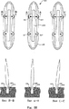
フィンタブの長さを、フィンボックスの長さよりも約20mm短くすることによって、前後方向へのフィンタブの調整を行うことができる。図19A及び19Bは、可能な最も前方の位置にあるフィン、及び、可能な最も後方の位置にあるフィンをそれぞれ示す。フィンタブ442は、フィンボックス中にて、前述の止めネジによって固定される。また、見て取ることができるように、フィンの前後の調整位置に関らず、フィンのブレード部は、フィンボックスの内側部分316により十分に支持されており、サーフボードの他の表面444に接触しない。
By making the length of the fin tab about 20 mm shorter than the length of the fin box, the fin tab can be adjusted in the front-rear direction. 19A and 19B show the fins in the foremost position possible and the fins in the most rearward position possible, respectively. The
<第3の好ましい実施形態>
図20及び21を見るならば、本発明のさらに他の実施形態である本実施形態では、前述の第2の実施形態と同様、右側フィンボックス400、中央フィンボックス402及び左側フィンボックス404が備えられる。これらフィンボックスの外面形状は、図17に示す第2の好ましい実施形態の場合と、いずれも同一である。
<Third Preferred Embodiment>
20 and 21, the present embodiment, which is still another embodiment of the present invention, includes a
ところが、本実施形態では、各フィンボックスの中央の凹陥部408の長さは、図21に示すように、2部分構成フィンタブ付きのフィン426における前方のフィンタブ421の前縁420から後方のフィンタブ423の後縁422までの長さと同一である。また、凹陥部の後方端壁面からは、何らの保持構造も突き出していない。
However, in the present embodiment, the length of the central recessed
右側フィンボックス400及び左側フィンボックス404においては、中央の凹陥部408が、サーフボードの下面418に対して傾斜する互いに平行の、左右両側の壁面を備える。一方、中央フィンボックスにおける中央の凹陥部は、左右両側の壁面が、互いに平行に、垂直方向へと延びる。
In the right-
図21A及び図21Bを参照するならば、2部分構成フィンタブ付きのフィン526についての、フィンボックス中での前後方向の位置調整は、凹陥部の長さが、前方のフィンタブ521の前縁520から後方のフィンタブ523の後縁522までの距離よりも長いことにより実現可能となっている。そのため、図21A及び図21Bに示すように、凹陥部530は、2部分構成のフィンタブ521及び523の全体の長さよりも10mm長く、フィン526について、図21Aに示す最も前方の位置と図21Bに示す最も後方の位置との間の等分点から、プラスまたはマイナス5mmだけの位置調整を可能にする。ここでも、第1外面516の全体の長さ及び幅は、フィン526のいずれの部分もサーフボードの他の表面532に接触しないようにするものである。
Referring to FIGS. 21A and 21B, for a
<第4の好ましい実施形態>
図22及び23を参照すると、本発明の第4の好ましい実施形態では、右側、中央及び左側のフィンボックス600が互いに同一である。フィンボックス600の外面形状は、前述の第2及び第3の実施形態の場合と同様である。但し、凹陥部608は、さらにシンプルになっており、矩形状断面の凹陥部であって、互いに向き合う左右の壁面及び両端の壁面は、互いに平行であって、かつ、前記第1外面612に垂直に延びている。
<Fourth Preferred Embodiment>
Referring to FIGS. 22 and 23, in the fourth preferred embodiment of the present invention, the right, middle and left
本実施形態においてフィンボックスには、凹陥部の左右両側に、いずれも2つの傾斜付きネジ切孔617が設けられており、一体構成のフィンタブ620を保持するための止めネジ614を受け入れるのに適したものとなっている。
In this embodiment, the fin box is provided with two inclined threaded
本実施形態のフィンボックスは、3フィン配列における左右のフィンにおいて、フィンタブがフィンの中央面に対して傾斜しているフィンタブ構成に適している。 The fin box of the present embodiment is suitable for a fin tab configuration in which the fin tab is inclined with respect to the center plane of the fin in the left and right fins in the three-fin arrangement.
<使用状態>
本発明のフィンボックスは、公知の方法によりサーフボードの本体に組み込むことができる。すなわち、サーフボードは、ガラスからなる材料で被覆する最終仕上げ工程の後、ガラス系表皮及び発泡体コア中へと機械研削を行うことにより適当な凹陥部を設けることができる。次いで、フィンボックスを差し込んで、適当な接着・結合剤でもって保持する。このような方法に代えて、空洞を、発泡体コア中に設けておき、ガラスからなる材料で被覆を行う前に、フィンボックスを差し込むことができる。この方法のためには、フィンボックスに、突起防壁240(図12及び15)を設けておき、樹脂が凹陥部224及び傾斜付きネジ切孔234及び235に流れ込まないようにする。
<Use state>
The fin box of the present invention can be incorporated into the body of the surfboard by a known method. That is, the surfboard can be provided with an appropriate recess by performing mechanical grinding into the glass-based skin and the foam core after the final finishing step of coating with a glass material. The fin box is then inserted and held with a suitable adhesive / bonding agent. Instead of such a method, a cavity can be provided in the foam core and the fin box can be inserted before coating with a material made of glass. For this method, the fin box is provided with a protrusion barrier 240 (FIGS. 12 and 15) so that the resin does not flow into the recessed portion 224 and the inclined threaded
Claims (10)
略細長状の本体からなり、該本体には、略矩形状の断面を有する凹陥部が、第1面で開口をなすように設けられており、前記凹陥部は、前記第1面の逆側の第2面に近い基部にまで延びており、前記凹陥部は前方端及び後方端を有し、
前記本体から外側へと延びる外周フランジが備えられ、前記フランジの第1面が、前記本体の第1面に連続しており、
バットレス部が、該フィンボックスの左側及び右側の少なくとも一方に設けられ、前記バットレス部が、前記本体の第1面から見ての前記フランジの裏面から前記本体の側面へと延びており、
傾斜付きネジ切孔が設けられ、該傾斜付きネジ切孔は、前記フランジ、前記バットレス部、及び、前記本体の左側または右側の面を突き抜けるように延びており、該傾斜付きネジ切孔に受け入れられた止めネジが、前記凹陥部に差し込まれた前記フィンタブの左側または右側の面に突き当てられるのに適するようになっており、前記止めネジにより前記フィンが前記フィンボックスに固定されていることを特徴とするフィンボックス。A fin box as a mounting structure for detachably attaching a fin to a main body such as a surfboard, wherein the fin is a combination of fin tabs, and the fin box is inserted and held in the surfboard And suitable for the mounting structure to receive and removably hold a plurality of shaped fin tabs so that the fins are fixed relative to the surfboard. Can be held detachable,
The main body is formed of a substantially elongated main body, and a concave portion having a substantially rectangular cross section is provided on the main body so as to form an opening on the first surface, and the concave portion is opposite to the first surface. Extending to a base near the second side of the recess, the recessed portion having a front end and a rear end,
An outer peripheral flange extending outward from the body, the first surface of the flange being continuous with the first surface of the body;
A buttress portion is provided on at least one of the left side and the right side of the fin box, and the buttress portion extends from the back surface of the flange as viewed from the first surface of the main body to the side surface of the main body ,
An inclined threaded hole is provided, and the inclined threaded hole extends through the flange, the buttress portion, and the left or right surface of the main body, and is received in the inclined threaded hole. set screw which is is being adapted to suit for being abutted against the left or right side of the Fintabu plugged into the recessed portion, said fins by the set screw that is fixed to the fin box A fin box featuring.
(a)前記サーフボード中に、細長い本体及び凹陥部からなるフィンボックスを嵌め込んだものを用意する工程と、
(b)前記フィンボックス中における傾斜付きネジ切孔中に備えられた止めネジを、前記フィンタブの差込を可能にするのに充分なまでに後退させる工程と、
(c)前記止めネジを前記フィンタブに接触させるようにねじ込む工程と、からなり、
前記フィンボックスには、前記本体から外側へと延びる外周フランジが備えられ、前記フランジの第1面が、前記本体の第1面に連続しており、また、バットレス部が、該フィンボックスの左側及び右側の少なくとも一方に設けられ、前記バットレス部が、前記本体の第1面から見ての前記フランジの裏面から前記本体の側面へと延び、さらに、傾斜付きネジ切孔が設けられ、該傾斜付きネジ切孔は、前記フランジ、前記バットレス部、及び、前記本体の左側または右側の面を突き抜けるように延びていることを特徴とするフィン取付け方法。A method of removably attaching a plurality of fin tabs for at least one fin of a surfboard,
(A) preparing a thing in which a fin box consisting of an elongated main body and a recessed portion is fitted in the surfboard;
(B) retracting a set screw provided in a beveled threaded hole in the fin box to a sufficient extent to allow insertion of the fin tab;
(C) a step of screwing the set screw so as to contact the fin tab;
The fin box includes an outer peripheral flange extending outward from the main body, the first surface of the flange is continuous with the first surface of the main body, and the buttress portion is on the left side of the fin box. And at least one of the right side, the buttress portion extends from the back surface of the flange to the side surface of the main body as viewed from the first surface of the main body, and is further provided with an inclined threaded hole. The attached threaded hole extends so as to penetrate through the flange, the buttress portion, and the left or right surface of the main body.
(a)細長い本体及び凹陥部からなり、前記本体から外側へと延びる外周フランジが備えられ、前記フランジの第1面が、前記本体の第1面に連続しており、また、バットレス部が、該フィンボックスの左側及び右側の少なくとも一方に設けられ、前記バットレス部が、前記本体の第1面から見ての前記フランジの裏面から前記本体の側面へと延び、傾斜付きネジ切孔が設けられ、該傾斜付きネジ切孔は、前記フランジ、前記バットレス部、及び、前記本体の左側または右側の面を突き抜けるように延びており、前記凹陥部は、その長手方向がサーフボードの長手方向に一致しており、前記凹陥部の長さが、前記フィンタブの長さよりも大きいフィンボックスを用意し、前記サーフボード中に、前記フィンボックスを嵌め込んだものを用意する工程と、
(b)前記フィンボックス中における傾斜付きネジ切孔中に備えられた止めネジを、前記フィンタブの差込を可能にするのに充分なまでに後退させる工程と、
(c)前記フィンタブを、前記凹陥部中にて前方または後方にずらすことにより、前記本体と前記フィンとの位置関係を調整する工程と、
(d)前記フィンの位置調整の後、前記サーフボードの使用中に前記フィンが前記フィンボックスの中で前方または後方に動くのを防ぐように、前記止めネジを、前記フランジ、前記バットレス部、及び、前記本体の左側または右側の面を少なくとも部分的に突き抜けるように前記第1の面からねじ込んで、前記止めネジの先端を前記フィンタブに接触させることで前記フィンを固定する工程とからなることを特徴とするフィン取付け方法。A method of removably and adjustably attaching a plurality of fin tabs for at least one fin of a surfboard, comprising:
(A) an outer peripheral flange including an elongated main body and a recessed portion and extending outward from the main body, the first surface of the flange being continuous with the first surface of the main body, and the buttress portion being Provided on at least one of the left side and the right side of the fin box, the buttress portion extends from the back surface of the flange as viewed from the first surface of the main body to the side surface of the main body, and is provided with an inclined threaded hole. The inclined threaded hole extends so as to penetrate the flange, the buttress portion, and the left or right surface of the main body, and the longitudinal direction of the recessed portion coincides with the longitudinal direction of the surfboard. A fin box in which the length of the recessed portion is larger than the length of the fin tab, and the surfboard with the fin box fitted therein is prepared. And a step,
(B) retracting a set screw provided in a beveled threaded hole in the fin box to a sufficient extent to allow insertion of the fin tab;
(C) adjusting the positional relationship between the main body and the fin by shifting the fin tab forward or backward in the recessed portion;
(D) after adjusting the position of the fins, the set screw, the flange, the buttress part, and the fins to prevent the fins from moving forward or backward in the fin box during use of the surfboard; Screwing from the first surface so as to at least partially penetrate the left or right surface of the main body, and fixing the fin by bringing the tip of the set screw into contact with the fin tab. Characteristic fin mounting method.
Applications Claiming Priority (10)
| Application Number | Priority Date | Filing Date | Title |
|---|---|---|---|
| AU2004907054A AU2004907054A0 (en) | 2004-12-13 | Fin attachment system | |
| AU2004907054 | 2004-12-13 | ||
| AU200407120 | 2004-12-14 | ||
| AU2004907120 | 2004-12-14 | ||
| AU2004907120A AU2004907120A0 (en) | 2004-12-14 | Fin attachment system | |
| AU2005100116A AU2005100116B4 (en) | 2004-12-13 | 2005-02-08 | Fin Attachment System |
| AU2005100116 | 2005-02-08 | ||
| US65433805P | 2005-02-18 | 2005-02-18 | |
| US60/654,338 | 2005-02-18 | ||
| PCT/IB2005/004167 WO2006077470A2 (en) | 2004-12-13 | 2005-12-13 | Fin attachment system |
Publications (3)
| Publication Number | Publication Date |
|---|---|
| JP2008534337A JP2008534337A (en) | 2008-08-28 |
| JP2008534337A5 JP2008534337A5 (en) | 2009-02-05 |
| JP4891258B2 true JP4891258B2 (en) | 2012-03-07 |
Family
ID=34426436
Family Applications (1)
| Application Number | Title | Priority Date | Filing Date |
|---|---|---|---|
| JP2007546230A Expired - Fee Related JP4891258B2 (en) | 2004-12-13 | 2005-12-13 | Fin mounting mechanism |
Country Status (3)
| Country | Link |
|---|---|
| US (1) | US7198532B2 (en) |
| JP (1) | JP4891258B2 (en) |
| AU (1) | AU2005100116B4 (en) |
Families Citing this family (18)
| Publication number | Priority date | Publication date | Assignee | Title |
|---|---|---|---|---|
| US7285031B2 (en) * | 2004-07-20 | 2007-10-23 | Larry William Allison | Fin systems |
| US20070283865A1 (en) | 2004-11-01 | 2007-12-13 | Bouncing Brain Innovations Season Two Subsidiary 14, Llc | Powered surfboard for preserving energy of surfer during paddling |
| US7497752B2 (en) * | 2004-12-13 | 2009-03-03 | John Field | Fin attachment system and method |
| US20080287018A1 (en) * | 2007-05-14 | 2008-11-20 | Bill Johnson | Stealth tail quad surfboard |
| CN101821159B (en) * | 2007-08-10 | 2013-04-03 | 菲恩控制系统有限公司 | Fin plug assembly and method of installation |
| AU2007251906A1 (en) * | 2007-08-22 | 2009-03-12 | Hyperaktiv Inc | Fin Attachment System |
| CA2662592A1 (en) * | 2008-04-15 | 2009-10-15 | Derek R. Leek | A thick, elleptical-planform fin for a water sports board |
| US8513581B2 (en) | 2008-05-20 | 2013-08-20 | Raytheon Company | Multi-caliber fuze kit and methods for same |
| AU2009251008A1 (en) * | 2009-09-09 | 2011-03-24 | Boomerboard, Llc | Powered surfboard |
| CN102666270A (en) * | 2009-11-10 | 2012-09-12 | 奥瑞根芬系统有限公司 | Fin collar with a fluid modification surface |
| US8951079B2 (en) * | 2010-07-01 | 2015-02-10 | Boomerboard, Llc | Motorized watercraft system with interchangeable motor module |
| CN103781700A (en) | 2011-06-30 | 2014-05-07 | 布姆邦德有限责任公司 | System for mounting a motorized cassette to a watercraft body |
| US8845374B2 (en) | 2011-07-07 | 2014-09-30 | Quint J. Higgins | Adjustable fin system |
| WO2013036536A2 (en) | 2011-09-07 | 2013-03-14 | Boomerboard, Llc | Inflatable watercraft with battery powered motorized cassette |
| AU2013204785C1 (en) | 2012-07-09 | 2019-09-05 | Fin Control Systems Pty. Limited | Fin Plug for Water Craft |
| AU2013204755A1 (en) | 2012-11-14 | 2014-05-29 | Fin Control Systems Pty. Limited | A Fin Plug for a Water Craft |
| WO2015089299A1 (en) * | 2013-12-13 | 2015-06-18 | Ganguli Julian | Insert of fin boxes of surfboards |
| US9457877B2 (en) * | 2014-08-24 | 2016-10-04 | John Hoon Chung | Fin system for watercraft |
Family Cites Families (21)
| Publication number | Priority date | Publication date | Assignee | Title |
|---|---|---|---|---|
| DE4038517A1 (en) | 1989-12-06 | 1991-06-13 | Zander Wolf Dietrich | Sailboard fin-mounting adaptor - has recess of cross=section matching fin shank and fits in bottom recess |
| AU669096B3 (en) | 1992-03-09 | 1996-05-23 | Fin Control Systems Pty. Limited | Surf fin fixing system |
| US5464359A (en) * | 1992-03-09 | 1995-11-07 | Fin Control Systems Pty. Limited | Surf fin fixing system |
| US5328397A (en) | 1992-03-09 | 1994-07-12 | Fin Control Systems Pty. Limited | Surf fin fixing system |
| AUPO269596A0 (en) | 1996-10-01 | 1996-10-24 | Sunbum Pty. Limited | Removable surf fin system |
| US5830025A (en) | 1997-09-15 | 1998-11-03 | Fleming; Marc W. | Fin box for a water sports board and method of installation |
| US6139383A (en) * | 1997-10-27 | 2000-10-31 | Pat-Tech Pty Ltd. | Fin assembly |
| AUPP744198A0 (en) | 1998-12-01 | 1998-12-24 | Milne, John De Courcey | Surfboards and improvements to surfboards |
| AUPQ637700A0 (en) | 2000-03-22 | 2000-04-15 | Low Pressure Systems | Spring locking surfboard fin system |
| BR8101826Y1 (en) | 2001-08-24 | 2009-05-05 | Constructive arrangement for the adjustment of removable surfboard side fins. | |
| US20030092333A1 (en) | 2001-11-13 | 2003-05-15 | Mccausland Bill | Removable and adjustable surf fin system |
| AUPS216302A0 (en) | 2002-05-07 | 2002-06-06 | Batt, Michael | Surfboard fin adjustment system |
| US6752674B2 (en) * | 2002-05-23 | 2004-06-22 | Oam, Llc | Sportboard fin attachment system |
| US6991503B2 (en) * | 2002-07-17 | 2006-01-31 | Antonio Garcia | Constructive disposition of adjustment of the removable lateral fins in surfboard |
| WO2004035377A1 (en) | 2002-10-17 | 2004-04-29 | Decourcey Pty Ltd | Surfboard fin box |
| US7001236B2 (en) * | 2003-12-23 | 2006-02-21 | Blake Jr David T | Dynamic fin system for watercraft |
| JP3102763U (en) * | 2004-01-09 | 2004-07-15 | 拱照 張 | surfboard |
| US7285031B2 (en) | 2004-07-20 | 2007-10-23 | Larry William Allison | Fin systems |
| US6991504B1 (en) * | 2004-08-16 | 2006-01-31 | English James A | Surfboard fin mounting system |
| WO2006021029A1 (en) | 2004-08-25 | 2006-03-02 | Decourcey Pty Ltd | Improved surfboard fin box and fin attachment system |
| US20060178061A1 (en) | 2005-01-10 | 2006-08-10 | Caldwell James M | Flex and resonance controlled watercraft |
-
2005
- 2005-02-08 AU AU2005100116A patent/AU2005100116B4/en not_active Expired
- 2005-12-13 US US11/300,642 patent/US7198532B2/en not_active Expired - Fee Related
- 2005-12-13 JP JP2007546230A patent/JP4891258B2/en not_active Expired - Fee Related
Also Published As
| Publication number | Publication date |
|---|---|
| AU2005100116A4 (en) | 2005-03-17 |
| US7198532B2 (en) | 2007-04-03 |
| JP2008534337A (en) | 2008-08-28 |
| US20060258239A1 (en) | 2006-11-16 |
| AU2005100116B4 (en) | 2005-09-08 |
Similar Documents
| Publication | Publication Date | Title |
|---|---|---|
| JP4891258B2 (en) | Fin mounting mechanism | |
| ES2453899T3 (en) | Cutting insert | |
| JP2008534337A5 (en) | ||
| JP5475865B2 (en) | Cutting tool and cutting insert for it | |
| JP5580400B2 (en) | Cutting tool assembly and its tool holder | |
| CN103118823B (en) | Point of a knife changes formula cutting element | |
| JP4377316B2 (en) | Chip removal tool | |
| JP5038333B2 (en) | Cutting tools | |
| EP2945765B1 (en) | Cutting tool with cutting insert having non-abutting side flanks | |
| JP5079684B2 (en) | Dispenser for leather cartridge | |
| JP2012522651A5 (en) | ||
| KR20110018312A (en) | Cutting tool and cutting insert therefor | |
| US7530459B2 (en) | Tool box for storing a tool handle and multiple tool tips | |
| JP2020090156A (en) | Fin for register | |
| JP2007533468A (en) | Adjustable deburring tool | |
| JP2013519537A (en) | Cutting inserts and cutting tools | |
| WO2006077470A2 (en) | Fin attachment system | |
| JP2021068579A5 (en) | ||
| JPH11104904A (en) | Tool holder for grooving and throwaway tip thereof | |
| KR20190128728A (en) | Hair Cutter and Hair Cutting Blade | |
| JPH0121832Y2 (en) | ||
| JPS5926402B2 (en) | boring tool | |
| KR100624555B1 (en) | A cutting tool having improved mounting structure | |
| CN113260474A (en) | Cutting insert and tool for machining a workpiece | |
| US668494A (en) | Tool-head. |
Legal Events
| Date | Code | Title | Description |
|---|---|---|---|
| A521 | Written amendment |
Free format text: JAPANESE INTERMEDIATE CODE: A523 Effective date: 20081212 |
|
| A621 | Written request for application examination |
Free format text: JAPANESE INTERMEDIATE CODE: A621 Effective date: 20081212 |
|
| A131 | Notification of reasons for refusal |
Free format text: JAPANESE INTERMEDIATE CODE: A131 Effective date: 20110111 |
|
| A601 | Written request for extension of time |
Free format text: JAPANESE INTERMEDIATE CODE: A601 Effective date: 20110411 |
|
| A602 | Written permission of extension of time |
Free format text: JAPANESE INTERMEDIATE CODE: A602 Effective date: 20110418 |
|
| A521 | Written amendment |
Free format text: JAPANESE INTERMEDIATE CODE: A523 Effective date: 20110711 |
|
| TRDD | Decision of grant or rejection written | ||
| A01 | Written decision to grant a patent or to grant a registration (utility model) |
Free format text: JAPANESE INTERMEDIATE CODE: A01 Effective date: 20111115 |
|
| A01 | Written decision to grant a patent or to grant a registration (utility model) |
Free format text: JAPANESE INTERMEDIATE CODE: A01 |
|
| A61 | First payment of annual fees (during grant procedure) |
Free format text: JAPANESE INTERMEDIATE CODE: A61 Effective date: 20111215 |
|
| R150 | Certificate of patent or registration of utility model |
Free format text: JAPANESE INTERMEDIATE CODE: R150 |
|
| FPAY | Renewal fee payment (event date is renewal date of database) |
Free format text: PAYMENT UNTIL: 20141222 Year of fee payment: 3 |
|
| LAPS | Cancellation because of no payment of annual fees |