JP4891148B2 - Recording apparatus and recording apparatus control method - Google Patents
Recording apparatus and recording apparatus control method Download PDFInfo
- Publication number
- JP4891148B2 JP4891148B2 JP2007130695A JP2007130695A JP4891148B2 JP 4891148 B2 JP4891148 B2 JP 4891148B2 JP 2007130695 A JP2007130695 A JP 2007130695A JP 2007130695 A JP2007130695 A JP 2007130695A JP 4891148 B2 JP4891148 B2 JP 4891148B2
- Authority
- JP
- Japan
- Prior art keywords
- paper
- roll sheet
- sheet
- detection
- information
- Prior art date
- Legal status (The legal status is an assumption and is not a legal conclusion. Google has not performed a legal analysis and makes no representation as to the accuracy of the status listed.)
- Active
Links
Images


Description
本発明は、記録装置及びその制御方法に関し、斜行やジャム等の要因に伴って実行するロールシートの取り付け直し時の処理に関する。
The present invention relates to a recording apparatus and a control method therefor , and relates to a process at the time of reattaching a roll sheet , which is executed in association with factors such as skew feeding and jamming.
従来のジャム処理として、カットマークを施し、このカットマークに従い、記録用紙を切断し、印画基準マークを検出し、位置決めを施すことが知られている(たとえば、特許文献1参照)。 As conventional jam processing, it is known to perform a cut mark, cut a recording sheet, detect a print reference mark, and perform positioning according to the cut mark (see, for example, Patent Document 1).
また、ジャム処理において、ジャムを除去するために、搬送ローラとカットマークによって排出動作を行うことが知られている(たとえば、特許文献2参照)。 In jam processing, it is known to perform a discharging operation using a conveyance roller and a cut mark in order to remove the jam (for example, see Patent Document 2).
さらに、ロール状記録媒体を用いる記録装置において、斜行検出処理の回数、実行頻度を低減し、印字処理結果が得られるまでの時間を短縮するとともに、斜行の誤検出を防止するように施す装置が知られている(たとえば、特許文献3参照)。
しかしながら、上記従来例のようにジャムや斜行の発生により用紙を取り付け位置に取り付ける際は、通常の用紙取り付け動作に伴う処理を行うので、時間がかかるという問題がある。
However, when the paper is attached to the attachment position due to the occurrence of a jam or skew as in the above-described conventional example, there is a problem that it takes time because the processing associated with the normal paper attachment operation is performed.
本発明は、ロールシートを再度取り付け直す際に、ロールシートを取り除かずに再セットした場合、入力動作等、無駄な処理を省略することができ、また、時間を短縮することができる記録装置及びその制御方法を提供することを目的とする。
The present invention, when re-installing the roll sheet again, when re-set without removing the roll sheet, it is possible to omit the input operation or the like, useless processing, also, the recording apparatus and it is possible to reduce the time An object is to provide a control method thereof.
本発明の記録装置は、ロールシート取り付け位置に取り付けられたロールシートに画像を記録する記録装置であって、前記取り付け位置に取り付けられたロールシートの情報を設定する設定手段と、ロールシートの有無を検出する検出手段と、前記取り付け位置に取り付けられたロールシートを取り外すための操作がなされてからロールシートの前記取り付け位置への取り付けの操作がなされるまでの間に、前記検出手段によりロールシートが無いことが検出されたか判断する判断手段と、前記判断手段により、前記検出手段によりロールシートが無いことが検出されたと判断された場合、前記設定手段により設定されたロールシートの情報の再設定を行わせ、前記検出手段によりロールシートが無いことが検出されなかったと判断された場合、前記設定手段により設定されたロールシートの情報を維持するよう制御する制御手段とを有することを特徴とする。The recording apparatus of the present invention is a recording apparatus that records an image on a roll sheet attached to a roll sheet attachment position, and includes setting means for setting information on the roll sheet attached to the attachment position, and the presence or absence of the roll sheet Detecting means for detecting the roll sheet, and after the operation for removing the roll sheet attached at the attachment position until the operation for attaching the roll sheet to the attachment position is performed, the roll sheet is detected by the detection means. Re-setting the roll sheet information set by the setting means when it is determined by the determining means that the detecting means detects that there is no roll sheet. If it is determined by the detection means that no roll sheet has been detected Characterized by a control means for controlling so as to maintain the information of the roll sheet set by the setting means.
本発明によれば、ロールシートを再度取り付け直す際に、ロールシートを取り除かずに再セットした場合、以前のロールシートの情報を使用することによって、ロールシートのセットに伴う動作を省略できるので、入力動作等、無駄な処理や時間を短縮することができるという効果を奏する。 According to the present invention, when re-installing the roll sheet again, when re-set without removing the roll sheet, by using information from the previous roll sheet, it is possible to omit the operation associated with the set of roll sheet, There is an effect that wasteful processing such as an input operation and time can be shortened.
発明を実施するための最良の形態は、次の実施例である。 The best mode for carrying out the invention is the following embodiment.
図1は、本発明の実施例1であるインクジェット記録装置PR1の概略を示す斜視図である。 FIG. 1 is a perspective view schematically showing an ink jet recording apparatus PR1 that is Embodiment 1 of the present invention.
インクジェット記録装置PR1は、キャリッジ10と、センサユニット11と、カッターユニット12と、ロール紙13と、用紙有無センサ14と、搬送ローラ15と、矢印16と、搬送ローラ解除位置17とを有する。また、インクジェット記録装置PR1は、プラテン18と、用紙基準検出位置19と、用紙先端20と、用紙基準検出点21と、用紙非基準位置22とを有する。
The ink jet recording apparatus PR1 includes a
ロール紙13は、最大60インチサイズの用紙である。また、ロール紙13を外すことによって、予め定型サイズにカットされているカット紙を取り付けることもできる。ロール紙13の上下が、搬送ローラ15によって挟まれている。搬送ローラ15が回転することによって、ロール紙13が紙送りされる。キャリッジ10は、図1中、右から左へ動作する。キャリッジ10に、記録ヘッドが搭載され、この記録ヘッドがインクを吐出することによって印字する。
The
センサユニット11は、キャリッジ10に搭載されている。センサユニット11は、様々なLEDを搭載し、用紙の端部、紙厚等を測定することができる。搬送ローラ15とキャリッジ10とを動作させることによって、様々な位置で、用紙の端部位置、紙厚を取得する。用紙基準検出位置19と用紙基準検出点21との差分に応じて、用紙の斜行量を検出する。用紙の斜行量検出については、後述する。
The
実施例1では、図1中、右側(キャリッジ10が記載されている側)を、「基準側」と呼び、逆側(左側)を、「非基準側」と呼ぶ。用紙基準検出位置19は、用紙先端20から150mm奥側の位置であり、用紙基準検出点21は、用紙基準検出位置19から300mm奥側の位置である。用紙基準検出位置19と用紙基準検出点21との差分に応じて、斜行量を検出する。用紙先端20は、キャリッジ10の動作方向非基準側に向かって、用紙基準端部から30mmにある。
In the first embodiment, the right side (side on which the
次に、用紙の斜行量を検出する動作について説明する。 Next, an operation for detecting the skew amount of the paper will be described.
図10、図11は、用紙が斜行していない場合に、斜行していないことを検出する動作の説明図であり、図1に示す状態を上から見た図である。 FIG. 10 and FIG. 11 are explanatory diagrams of an operation for detecting that the sheet is not skewed when the sheet is not skewed, and is a view of the state shown in FIG. 1 as viewed from above.
ここで、図1のプラテン18上の基準側(図1では右側)には、ロール紙の取り付け位置を示す基準線(不図示)が引いてあり、ユーザは、上記基準線に合わせてロール紙をセットする。図1において、ユーザは、ロール紙の右側端部を上記基準線に合わせて取り付ける。そして、斜行せずにロール紙を上記基準線の位置に取り付ければ、キャリッジ10に搭載されているセンサユニット11が検出した記録紙端部の位置は、上記基準線の位置となるはずである。そこで、制御部は、上記基準線の位置を論理的な検出位置として予め記憶している。
Here, a reference line (not shown) indicating the attachment position of the roll paper is drawn on the reference side (right side in FIG. 1) on the
斜行を検出するためには、まず、用紙基準検出位置19を、キャリッジ10に搭載されているセンサユニット11が読み取る。キャリッジ10は、図10に示すように、左右にのみ動作するので、センサユニット11が読み取る位置61に、用紙基準検出位置19が来るように、搬送ローラ15がロール紙13を予め紙送りする。センサユニット11から用紙上に光を当て、反射した光を、センサユニット11が受光する。用紙上の受光量とプラテン上の受光量との違いから、予め閾値を決定し、図10中、矢印のように、キャリッジ10を、用紙上から用紙外へ動作させる。そして、センサユニット11が検出した受光量が上記閾値に達したときに、用紙端部が上記読み取る位置61に到達したと判断する。
In order to detect the skew, first, the
ここで、ロール紙が斜行せずに正しく取り付けられている場合、図10に示すようになる。そして、センサユニット11が検出した記録紙端部の位置と、理論的な検出位置との差分が±5mm以下であれば、斜行せずに正常に取り付けられたと判断し、図11に示す動作に移る。つまり、図11において、19から21に向けて、上記ロール紙の取り付け位置を示す基準線(不図示)が引いてあり、読み取る位置61と交わる点になる(図11における21が論理的な検出位置である)。
Here, when the roll paper is correctly attached without being skewed, it is as shown in FIG. Then, if the difference between the position of the recording paper edge detected by the
図11は、用紙基準検出点21を読み取るときの動作を示す図である。
FIG. 11 is a diagram illustrating an operation when the paper
図10に関連する動作の後に、用紙基準検出点21を読み取るために、搬送ローラ15がロール紙13を送り出し、センサユニット11が読み取る位置61に、用紙基準検出点21が来るように、ロール紙13を送り出す。その後は、図10で説明したと同様に、図11中、矢印の方向に、キャリッジ10を動作させ、その位置を読み取ることによって、用紙基準検出点21の位置を検出する。斜行が全く無いので、用紙基準検出位置19と用紙基準検出点21との左右方向の検出位置は、同じ位置になり、差が無いので、斜行していないと判断することができる。
After the operation related to FIG. 10, in order to read the paper
図12、図13は、用紙が斜行している場合の検出動作の説明図であり、図1に示す状態を上から見た図である。 12 and 13 are explanatory diagrams of the detection operation when the paper is skewed, and is a view of the state shown in FIG. 1 as viewed from above.
図12は、本発明を適用できる用紙斜行時の基準側用紙端部検出動作を示す図である。 FIG. 12 is a diagram illustrating the reference side paper edge detection operation when the paper is skewed to which the present invention can be applied.
用紙基準検出位置19の検出動作は、図10と同様である。斜行検出する場合、図10における理論的な検出位置からの差分によって、±5mm以上誤差があれば、斜行エラーとして検出し、再度取付けることを、ユーザに促す。センサユニット11が検出した記録紙端部の位置と、理論的な検出位置との差分が、±5mm以下であれば、図13に示す動作に移る。
The detection operation of the paper
上記理論的な検出位置は、図11において、19から21に向けて上記ロール紙の取り付け位置を示す基準線(不図示)が引いてあり、読み取る位置60と交わる点であり、図11における論理的な検出点21である。また、上記理論的な検出位置は、図12において、ロール紙の一番上から垂直に下ろした位置と読み取る位置60との交差点である。
The theoretical detection position is a point at which a reference line (not shown) indicating the attachment position of the roll paper is drawn from 19 to 21 in FIG. This is a
図13は、図12に関する動作が終了した後に、用紙が斜行している場合に、用紙基準検出点21を読み取るときの動作を示す図である。図13中、点線部は、図12に示す用紙の位置を表す。
FIG. 13 is a diagram illustrating an operation when the paper
図11に関する説明と同様に、用紙基準検出点21を読み取るために、搬送ローラ15がロール紙13を送り出し、センサユニット11が読み取る位置60に、用紙基準検出点21が来るように、ロール紙13を送り出す。そして、キャリッジ10を動作し、用紙基準検出点21の位置を検出する。斜行量は、この用紙基準検出位置19と用紙基準検出点21との差分に応じて判断する。図13中、破線部分70を拡大したものを、図13の下の部分に示す。差分71が、用紙基準検出位置19と用紙基準検出点21との差分であり、この差分71の値が、斜行量である。斜行エラーと判断する基準は、用紙種類毎に、本体に設定されている。一般的には、斜行量が1mmであれば、エラーであると判断する。また、緩めに判断基準を設定することもでき、この場合は、斜行量が2mm以上であれば、エラーであると判断する。
Similarly to the description with reference to FIG. 11, in order to read the paper
用紙基準検出点21と用紙非基準位置22とを結ぶ線は水平であり、この2つの位置21、22に基づいて、用紙幅を算出する。また、キャリッジ10は、カッターユニット12を搭載し、キャリッジ10を非基準側の壁に突き当てると、カッターユニット12内の刃が突出し、この刃が用紙を切断する。
A line connecting the paper
プラテン18がロール紙13を支え、搬送ローラ15が、ロール紙13を紙送りし、プラテン18上を紙が前後することによって、自動給紙動作や印字が行われる。用紙有無センサ14は、ピンチローラよりも奥側のプラテン18上に設けられ、用紙がプラテン18上に有るか無いかを判断する。センサ14による用紙の有無に基づいて、用紙再セット時に、用紙が抜かれ、他の用紙が取り付けられた可能性があるのか、同じ用紙がついたままであるのかを判断する。
The
すなわち、センサが紙無しを検出すると、用紙が除去されたと判断することができる。また、図示しない搬送ローラ解除レバーが設けられ、この上記搬送ローラ解除レバーによって、搬送ローラ15を、矢印16が示すように、上下に移動可能である。搬送ローラ15が位置17にあると、用紙が挟まれている状態が解除され、用紙が自由になるので、ユーザは、用紙の取り外し、取り付けを行うことができる。
That is, when the sensor detects no paper, it can be determined that the paper has been removed. Further, a conveyance roller release lever (not shown) is provided, and the
搬送ローラ解除レバーに、図示しないロック機構が設けられているが、キャリッジ10等が動作しているときは、上記搬送ローラ解除レバーを解除することができない。
Although a lock mechanism (not shown) is provided on the transport roller release lever, the transport roller release lever cannot be released when the
また、上記搬送ローラ解除レバーによって搬送ローラ15が解除されているかどうかを、図示しないセンサが判断し、搬送ローラ15が解除されたことをトリガとして、用紙取り付け、取り外し動作が行われていると判断する。
Further, a sensor (not shown) determines whether or not the
その後に、上記搬送ローラ解除レバーの操作によって、搬送ローラ解除位置17から搬送ローラ15の位置に、搬送ローラ15がセットされたときに、用紙の取り付け直しが終了したと判断する。すなわち、搬送ローラ15が、解除位置にあれば、用紙の取り付け、直しの最中であり、この間に、用紙が除去されたかどうかを、用紙有無センサ14が判断する。
Thereafter, when the
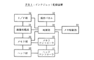
図2は、インクジェット記録装置PR1の構成を示すブロック図である。 FIG. 2 is a block diagram showing a configuration of the ink jet recording apparatus PR1.
インクジェット記録装置PR1は、制御部30と、画像処理部31と、メカ駆動部33と、I/F(インタフェース)部34と、メモリコントローラ35と、メモリ部36と、ヘッドコントローラ37と、ヘッド部38とを有する。
The ink jet recording apparatus PR1 includes a
制御部30は、インクジェット記録装置PR1の全体を制御する。
The
I/F(インタフェース)部34と、図示しないホストコンピュータとが接続されている。ホストコンピュータから、コマンドと印字を行う記録データとが送られ、このコマンドに応じて、インクジェット記録装置PR1が動作することによって、記録データを用紙に記録する。
An I / F (interface)
また、インクジェット記録装置PR1の情報を、ホストコンピュータに、コマンド及びデータを送ることによって、インクジェット記録装置PR1の状態を通知することができ、これによって、ユーザに用紙情報を通知することができる。I/F部34として、セントロニクス、USBインタフェースが用いられる。
Further, by sending a command and data to the host computer, information on the ink jet recording apparatus PR1 can be notified of the state of the ink jet recording apparatus PR1, thereby making it possible to notify the user of paper information. As the I /
画像処理部31は、I/F部34から受信した記録データ(多値画像データ)について、γ補正、色処理、拡大/縮小処理、2値化等を行い、メモリ、ASIC、DSP、RISCチップ等によって構成されている。
The
本体コストを下げるために、ホスト側のドライバやRIP(Raster Image Processor)が、画像処理部31の機能を実行するようにしてもよい。
In order to reduce the main body cost, a driver on the host side or a RIP (Raster Image Processor) may execute the function of the
画像処理部31における処理の最終段で、ドットパターンに展開された印字データを、メモリ部36に一旦蓄積する。メモリ部36は、図示しない記録ヘッドが、主走査方向に1回スキャンして記録するために必要な1バンド分以上のメモリ容量を有する。メモリ部36は、後述する用紙端部情報等、本体情報の記憶にも用いられる。
In the final stage of processing in the
メモリコントローラ35が、メモリ部36へ印字データを書込み/読み出しし、画像処理部31のDSP又はRISCチップの制御の下に、メモリ部36にアドレス信号と書込み/読み出しタイミング信号とを生成する。また、メモリ部36から印字データを読み出す場合、ヘッドコントローラ37からの読み出し信号に同期して、ヘッドコントローラ37に出力する。
The
ヘッドコントローラ37は、図示しないリニアスケールからの信号に基づいて、ヘッド部38でのインク吐出のタイミング信号やヒートパルスを、制御部30の制御によって、生成する。ヘッド部38は、各色インクに対応する記録ヘッドによって構成され、制御部30とヘッドコントローラ37とによって、ヒータ部を加熱し、インクを吐出することによって、紙面へ画像記録する。ヘッド部38は、実際には、メカ駆動部33のキャリッジ10上に取り付けられている。
The
メカ駆動部33は,記録ヘッドを主走査方向に移動させるためのキャリッジ10と、キャリッジ駆動部と記録用紙とを動作させる用紙制御部と、記録ヘッドのインク詰りを回復する回復ユニット部と、用紙を巻き取る巻き取り装置部と、その他センサとを有する。
The
用紙端部を検出するセンサユニットは、キャリッジ10上に取り付けられている。このキャリッジ10を移動させ、図示しないリニアスケールからの信号に基づいて、キャリッジ10に搭載されているセンサが、キャリッジ10が変化した位置を算出し、用紙の幅方向の端部情報を得る。
A sensor unit for detecting the edge of the sheet is mounted on the
また、キャリッジ10を、ある位置に固定し、搬送ローラ15を動作させ、用紙を動作させる。これによって、キャリッジ10に搭載されているセンサが、変化した搬送ローラ15の位置を、先のリニアスケールとは別のリニアスケール(図示せず)からの信号に基づいて、算出し、先端位置情報を得る。これら検出した位置情報等の用紙情報が、メモリ部36に保存される。
Further, the
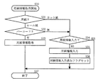
図3は、実施例1において、ユーザが用紙取り付けする際の制御部30の動作を示すフローチャートである。
FIG. 3 is a flowchart illustrating the operation of the
このフローチャートは、ユーザが、用紙の取り付け又は取り付け直しを行っている際に、用紙有無センサ14が、用紙無しであるかどうかを監視するだけである。用紙有無センサが用紙無しを検出すると、用紙が除去されたと判断することができ、用紙有りを検出すると、同じ用紙が取り付けられていると判断できる。これによって、ユーザが、同じ用紙を引き続き使用しているのか、用紙が取り除かれ、違う用紙が取り付けられた可能性があるのかを判断することができる。違う用紙が取り付けられたと判断した場合、用紙情報フラグをクリアする。用紙情報フラグをクリアすることによって、後述の位置情報や、基準位置を検出済みかどうかのフラグ、幅検出フラグがクリアされ、これらを再設定する動作を行う。この再設定の動作は後述する。
This flowchart only monitors whether the
本フローチャート終了後に、用紙を自動給紙し、用紙の情報を得る。ユーザが、用紙を取り付けし、取り外しを行う場合、たとえば、搬送ローラ15の上記搬送ローラ解除レバーを操作し、搬送ローラ15を解除することによって、用紙を自由に動かせる状態にする。よって、搬送ローラ15の上記搬送ローラ解除レバーが解除されたときに、用紙取り付け/取り外しを開始する(S10)。
After this flowchart is completed, the paper is automatically fed to obtain paper information. When the user attaches and removes a sheet, for example, the sheet is freely moved by operating the conveyance roller release lever of the
同じ用紙でも状態が変わるので、S11で、処理終了後の用紙自動検出において検出する必要がある用紙情報を、一部クリアする。たとえば、用紙基準位置等は、同じ用紙でも、取り付け位置に応じて変化するので、自動検出の際に、用紙基準位置等を再度読み込み直す必要がある。このために、位置情報や、基準位置を検出済みかどうかを示すフラグを、クリアする。このフラグによって、用紙の幅を検出したかどうかを判断することができる。 Since the state changes even for the same sheet, a part of sheet information that needs to be detected in the automatic sheet detection after the process is completed is cleared in S11. For example, since the paper reference position and the like change depending on the attachment position even with the same paper, it is necessary to read the paper reference position and the like again at the time of automatic detection. For this purpose, the position information and the flag indicating whether the reference position has been detected are cleared. With this flag, it is possible to determine whether or not the width of the sheet has been detected.
S13で、用紙有を確認し、S14で、搬送ローラ15がセットされるまでの間に、用紙有無センサ14が、用紙無しになるかどうかを判断する。搬送ローラ15が解除された状態の位置17で用紙無になると、用紙が取り外されたと判断する。用紙が取り外された場合、別の用紙が取り付けられる可能性があるので、続く自動でのロード動作は、全ての検出・設定を行う必要がある。このために、S12で、用紙情報をクリアし、S16で、終了する。搬送ローラ15が解除された状態の位置17で、常に用紙有の状態であれば、同じ用紙がセットされたものとする。そして、続く用紙自動検出において変化しない値は、保持したまま、S15で、搬送ローラ15の上記搬送ローラ解除レバーをロックし、解除できない状態にし、S16で、終了する。
In S13, the presence of a sheet is confirmed. In S14, the sheet presence /
図4は、ユーザが用紙をセットし終わった(図3のS16に示す制御を制御部30が行った後)後に、制御部30によって実行される、用紙の情報を自動的に検出する動作を示すフローチャートである。
FIG. 4 shows an operation of automatically detecting paper information performed by the
図4に示す動作における用紙は、ロール紙である。実際には、用紙情報が書き込まれたバーコードを読み取る等、その他の動作が行われるが、ここでは省略する。また、S21〜S25、S27の動作は、検出位置異常等、異常時には、終了処理(S29)を行い、次の動作には移らずに、終了する。図3に示す終了処理が行われると(S16)、上記搬送ローラ解除レバーがロックされた後に、ユーザによる用紙の取り付け又は再セットが行われ、正常完了したと判断し、用紙の端部を検出する動作を開始する(S20)。 The paper in the operation shown in FIG. 4 is roll paper. Actually, other operations such as reading a barcode on which paper information is written are performed, but are omitted here. Also, the operations of S21 to S25 and S27 are terminated without performing the next operation (S29) when an abnormality such as a detection position abnormality occurs, and the next operation is not performed. When the end process shown in FIG. 3 is performed (S16), after the transport roller release lever is locked, the user mounts or resets the sheet, and determines that the sheet is normally completed and detects the end of the sheet. The operation to start is started (S20).
まず、S21で、端部検出の閾値を検出するために、用紙を現在の位置から150mm送り、用紙上とプラテン18上とで、センサを使用し、端部検出時の閾値を求める。
First, in step S21, in order to detect a threshold value for detecting an edge, the sheet is fed 150 mm from the current position, and a sensor is used on the sheet and on the
S22で、先端を検出するための用紙基準仮検出を行う。つまり、用紙先端における用紙の紙浮きを考慮し、用紙基準端部から一定の距離で読むために、用紙基準仮検出を行う。キャリッジ10を、用紙上からプラテン18上に動作し、センサユニット11のセンサが、変化したキャリッジ10の位置から、用紙基準位置を算出する。
In S22, paper reference temporary detection for detecting the leading edge is performed. In other words, the paper reference temporary detection is performed in order to read the paper at a certain distance from the paper reference edge in consideration of the paper floating at the front edge of the paper. The
S23で、用紙先端20を検出する。これは、先ほど算出した用紙基準端部から30mmの位置に、センサユニットが位置するように、キャリッジ10を固定し、搬送ローラ15によって用紙を巻き戻すことによって、用紙先端20の位置を算出する。S24で、用紙先端20から一定の位置(150mmの位置)で、用紙基準検出位置19を検出する。この検出は、斜行検出用に一時覚えておくだけの検査である。その後、S25で、用紙基準検出位置19よりも300mm、搬送ローラ15で用紙を送り、その位置で、用紙基準検出点21を検出し、S24の位置情報と比較する。この比較結果が、閾値以上であれば、斜行エラーであると判断し、異常時の動作に移り、S29で、終了する。
In S23, the leading
この閾値は、用紙種類や斜行検出の緩め、通常、きつめ等の設定によっても変わる。普通紙のロール紙における通常の斜行を検出する場合、上記閾値を、1mmに設定し、カット紙における上記閾値を、2mmに設定する。S26で、用紙情報の1つである幅検出済みフラグによって幅検出を行ったかどうかを判断する。この幅検出済みフラグは、用紙情報一部クリア(S11)では、クリアされないフラグである。よって、幅検出フラグがセットされていれば、以前に取り付けられていた用紙と同じ用紙が再セットされていると判断することができる。S26で幅検出が済んでいない場合、以前幅検出した用紙と異なる用紙が取り付けられた可能性があるので、S27で、用紙非基準位置22を検出する。 This threshold value also varies depending on settings such as the paper type, slack detection, and normal, tightness. When detecting normal skew in plain paper roll paper, the threshold value is set to 1 mm, and the threshold value in cut paper is set to 2 mm. In S26, it is determined whether or not width detection has been performed based on a width detection completed flag which is one of the sheet information. This width detected flag is a flag that is not cleared when the paper information is partially cleared (S11). Therefore, if the width detection flag is set, it can be determined that the same paper as that previously attached has been reset. If the width detection has not been completed in S26, there is a possibility that a paper different from the paper whose width has been detected before is attached, so the paper non-reference position 22 is detected in S27.
用紙基準検出点21と用紙非基準位置22とによって、用紙幅を算出する。すなわち、幅検出は、用紙非基準位置22の検出である。幅検出が済むと、S28で、用紙幅検出フラグをセットし、終了する。S26で幅検出が済んでいると判断されれば、以前の用紙と同じ用紙であり、幅は大幅に変化していないので、幅検出動作(S27、S28)をスキップする。この場合、以前に保存されている用紙幅情報を、そのまま使用するので、用紙幅検出動作(S27、S28)を省略することができる。また、以前検出した用紙基準位置と用紙非基準位置とに応じて算出した用紙幅情報に基づいて、新たな基準位置から幅情報を加算したものが、用紙非基準位置である。
The paper width is calculated from the paper
ここで、斜行した場合等は、用紙幅が変化するので、斜行量に基づいて、用紙幅を算出し直すようにしてもよい。用紙基準位置と用紙非基準位置として、以前検出した値を使用するようにしてもよく、幅情報を使用して必要な情報を算出するようにしてもよい。 Here, since the paper width changes when skewed, the paper width may be recalculated based on the skew amount. As the paper reference position and the paper non-reference position, previously detected values may be used, or necessary information may be calculated using width information.
また、実施例1は、ロール紙を使用しているが、カット紙の幅検出を先に行う等、検出順序等動作は異なるが、用紙幅の検出動作(S26〜S28)を省略することができる。よって、端部検出順序は、どのようなものであってもよい。 In the first embodiment, roll paper is used, but the detection operation (S26 to S28) of the paper width is omitted, although the detection order and other operations are different, such as detecting the width of the cut paper first. it can. Therefore, the end detection order may be any.
上記のように、ユーザが用紙を取り付け直ししている際に、用紙有り無しを検出し、用紙有り状態が維持されていれば、幅検出(用紙非基準位置検出)動作を省略することができ、時間を短縮することができる。 As described above, the width detection (paper non-reference position detection) operation can be omitted if the presence / absence of the paper is detected while the paper is being reattached by the user. , Can save time.
実施例1では、搬送ローラ15を解除することによって、用紙の有無の監視を開始するが、ユーザが用紙を引き抜いた場合を考慮し、幅検出済み後に、用紙の有無監視を常に行う等、別のタイミングで、用紙の有無を監視するようにしてもよい。また、このように引き抜いた場合等のために、引き抜いたタイミングで、用紙取り外しを開始するようにしてもよい。また、操作パネル上で用紙をセット開始と取り外し要求とを行ったとき等、別のタイミングで、用紙取り外しを開始するようにしてもよい。
In the first exemplary embodiment, monitoring of the presence / absence of paper is started by releasing the
また、用紙の有無と搬送ローラ15の解除とを、ポーリングによって実行するが、割り込みによって、用紙の有無と搬送ローラ15の解除とを実行するようにしてもよく、ユーザの用紙取り付け中に用紙の有無が分かれば、どのように実行してもよい。
The presence / absence of the paper and the release of the
たとえば、操作パネル上等で、斜行検出機能をOFFすることができる等、様々な順序や、組み合わせが考えられるので、幅を検出する手段であれば、どのような手段であってもよい。また、斜行検出が厳しいので、幅にはあまり影響しないが、幅は斜行量によって変化するので、斜行量に基づいて、用紙幅を算出し直すようにしてもよい。
For example, various means and combinations can be considered such that the skew detection function can be turned off on the operation panel or the like, and any means may be used as long as it is a means for detecting the width. Further, since the skew detection is severe, the width is not greatly affected, but the width changes depending on the skew amount. Therefore, the paper width may be recalculated based on the skew amount.
図5は、本発明の実施例2であるインクジェット記録装置PR2において、ユーザが用紙をセットし終わった後における用紙情報取得時に制御部30が行う動作を示すフローチャートである。
FIG. 5 is a flowchart illustrating an operation performed by the
なお、インクジェット記録装置PR2の構成は、インクジェット記録装置PR1の構成と同様であり、つまり、図1、図2、図3に示す構成、動作と同様の構成、動作を有する。 Note that the configuration of the inkjet recording apparatus PR2 is the same as the configuration of the inkjet recording apparatus PR1, that is, has the same configuration and operation as the configurations and operations shown in FIG. 1, FIG. 2, and FIG.
実施例2では、用紙情報として、用紙種類と用紙長さとを入力する。用紙種類は、図4で説明した端部検出動作に反映する。たとえば、用紙種類毎に、斜行検出をする、しない等の設定、上記のような斜行検出の緩め、通常、きつめの設定や、搬送速度等、多くの用紙を問題なく自動でロードし、印刷する等、サポートするために必要である。また、用紙長さを管理することができる。 In the second embodiment, the paper type and the paper length are input as the paper information. The paper type is reflected in the edge detection operation described with reference to FIG. For example, for each paper type, many papers are automatically loaded without problems, such as setting whether or not to perform skew detection, loosening skew detection as described above, normal and tight settings, and transport speed. Necessary to support, printing, etc. In addition, the paper length can be managed.
用紙情報は、ここでは、用紙種類と用紙長さとの2つであるが、用紙に付随する他の情報であってもよい。この用紙情報を取得する動作(S30)は、図3に示す終了動作(S16)後に開始する。まず、S31で、現在取り付ける用紙が、ロール紙であるのかカット紙であるのかを判断する。ロール紙である場合、用紙種類等の用紙情報を、ロール紙上に、バーコードとして記載するので、ユーザが入力する必要が無く、給紙が完了する。したがって、S32で、キャリッジ10上に搭載されているセンサユニット11のセンサが、ロール紙上に記載されているバーコードを検出する。
Here, the paper information includes two types, that is, the paper type and the paper length, but may be other information attached to the paper. The operation for acquiring the paper information (S30) starts after the end operation (S16) shown in FIG. First, in S31, it is determined whether the currently attached paper is roll paper or cut paper. In the case of roll paper, paper information such as paper type is described as a barcode on the roll paper, so that it is not necessary for the user to input and paper feed is completed. Therefore, in S32, the sensor of the
用紙種類等の用紙情報が記載されているバーコードがあれば、センサユニット11のセンサが上記バーコードを読み取ることによって、用紙情報を取得し、S37で、終了する。用紙先端20に、上記バーコードを記載する必要があり、用紙排紙時、バーコードを記載する。
If there is a bar code in which paper information such as the paper type is described, the sensor of the
印字物がある場合や、後述する巻き取り装置を使用する場合は、先端20にバーコードを記載することができない。したがって、用紙種類と長さとのみを、先端20ではない場所に記載し、用紙を取り付けるときに、ユーザがバーコードを入力する。用紙を再セットする場合、用紙を切断し、先端20にバーコードを記載し、現在の用紙種類や残り長さをユーザが覚えて、入力する必要がある。
When there is a printed matter or when a winding device described later is used, a barcode cannot be written on the
実施例2では、用紙を外さずに、同じ用紙を取り付けた場合、以降の処理によって、上記入力作業を省く。S31で、カット紙であると判断された場合や、S32で、バーコードが無いと判断された場合、S34で、用紙情報を入力したかどうかを調べる。用紙情報を入力したかどうかを示すフラグは、図4に示す幅検出済みフラグと同様に、図3に示す用紙情報一部クリア(S11)では、クリアしない。 In the second embodiment, when the same paper is attached without removing the paper, the above input operation is omitted by the subsequent processing. If it is determined in S31 that the sheet is a cut sheet, or if it is determined in S32 that there is no barcode, it is checked in S34 whether or not sheet information has been input. Similarly to the width detected flag shown in FIG. 4, the flag indicating whether or not the paper information is input is not cleared in the paper information partial clear (S11) shown in FIG.
よって、用紙情報を入力したら、以前に取り付けられていた用紙と同じ用紙を、再セットしたことになるので、同じ用紙であると判断し、用紙種類等の用紙情報を受け継ぎ、用紙情報を入力せずに、S37で、終了する。S34で入力済みではないと判断されると、S35で、操作パネル上で、用紙種類等の用紙情報の入力を求め、ユーザが用紙種類を選択する等、必要な情報を入力することによって、用紙情報を決定する。用紙情報が決定された後は、S36で、用紙情報入力済みフラグをセットし、S37で、終了する。 Therefore, when paper information is entered, the same paper as previously loaded paper is set again, so it is determined that it is the same paper, inherits paper information such as paper type, and enters paper information. In step S37, the process ends. If it is determined in S34 that the input has not been completed, in S35, the user is requested to input paper information such as the paper type on the operation panel, and the user inputs the necessary information such as selecting the paper type. Determine information. After the paper information is determined, the paper information input flag is set in S36, and the process ends in S37.
実施例2によれば、同じ用紙を取り付け直す場合、バーコードを印字する手間と、用紙情報を覚えて入力する手間とを省き、何もせずに用紙の取り付けを行うことができる。したがって、ユーザの手間や時間を短縮することができる。
According to the second embodiment, when the same paper is reattached, the trouble of printing the barcode and the trouble of learning and inputting the paper information can be saved, and the paper can be attached without doing anything. Therefore, the user's labor and time can be reduced.
図6は、本発明の実施例3の巻き取り装置を使用したインクジェット記録装置PR3の概略を示す図である。 FIG. 6 is a diagram showing an outline of an ink jet recording apparatus PR3 using the winding device of Embodiment 3 of the present invention.
インクジェット記録装置PR3は、インクジェット記録装置PR1において、巻き取り装置を装着し、動作させる実施例である。 The ink jet recording apparatus PR3 is an embodiment in which a winding device is mounted and operated in the ink jet recording apparatus PR1.
巻き芯42は、巻き取り装置(図示せず)に装着されている巻き芯であり、この巻き芯42に、ロール紙を貼り付け、巻き取り装置が巻き取ることによって、ロール紙13に印字することができる。
The winding core 42 is a winding core attached to a winding device (not shown). A roll paper is attached to the winding core 42, and the winding device winds up to print on the
センサ(図示せず)が、巻き取り装置よりも下に設けられ、印字される用紙が弛むと、この用紙を検出し、ある一定量、巻き取り動作を行い、これによって、用紙を巻き取る。 A sensor (not shown) is provided below the take-up device. When the paper to be printed is loosened, this paper is detected, and a certain amount of take-up operation is performed, thereby taking up the paper.
用紙先端位置41は、搬送ローラ15の上記搬送ローラ解除レバーを解除し、再セットしたときの先端検出を省略した場合における用紙先端の位置である。上記「用紙先端」を、内部的に管理し、たとえば、用紙残量を管理するために、用紙取り付け時にセンサが読み取った先端や、カットした物理的な現在の先端や、次ページのページ先端等である。
The paper leading
ここでは、次ページのページ先端位置41のみを更新する。この位置41は、搬送ローラ15に挟み込まれる位置から、8mm手前の位置であり、通常、用紙をセットして待機するページの先端である。ページ先端位置41は、インクジェット記録装置PR3が待機状態であるときにおけるページの先端の位置である。すなわち、搬送ローラ15の上記搬送ローラ解除レバーを解除し、セットするまで、先端が動かされなかったとして動作する。
Here, only the page leading
この先端位置41は、一例であり、安全のために、先端位置41を、たとえば30mm後ろに設定するようにしてもよい。また、巻き取りの形態は、どのようなものであってもよいが、既に、このような状態であると、先端を検出することに時間がかかるか、又は、不可能な場合である。用紙基準検出位置43、44は、図1に示す用紙基準検出位置19、用紙基準検出点21と同じ意味合いのものである。ページ先端位置41から150mm奥側の位置が、用紙基準検出位置43であり、そこから300mm奥側の位置が、用紙基準検出位置44である。この用紙基準検出位置43と44との差分に応じて、斜行検出を、図1に示す場合と同様に行う。
The
図7は、インクジェット記録装置PR3において、制御部30が実行する、用紙端部を検出する動作を示すフローチャートである。
FIG. 7 is a flowchart showing an operation of detecting the edge of the sheet, which is executed by the
図7に示す動作は、図3に示す動作の後の動作であり、巻き取り装置を使用中である場合には、先端検出動作を行わない。このようにすることによって、斜行やジャム発生時等のメンテナンスの際に、用紙を切断せずに、また、用紙を取り外さずに位置合わせし、用紙を取り付けることができる。また、巻き取り装置使用中であるかどうかを判定することによって、先端を読める状態であるにもかかわらず読まない等の動作を減少させることができる。 The operation shown in FIG. 7 is an operation after the operation shown in FIG. 3, and the tip detection operation is not performed when the winding device is in use. By doing so, it is possible to align and attach the paper without cutting the paper and without removing the paper at the time of maintenance such as skew or jam. Further, by determining whether or not the winding device is in use, it is possible to reduce an operation such as not reading even though the tip can be read.
S40で、端部検出を開始する。図4に示す場合と同様に、S41で、センサ光量を調整し、続いて、先端検出動作をする前に、S42で、巻き取り装置が使用中であるかどうかを判断する。 In S40, edge detection is started. As in the case shown in FIG. 4, the sensor light amount is adjusted in S41, and then, before performing the tip detection operation, it is determined in S42 whether the winding device is in use.
「巻き取り装置が使用中」は、ユーザが、操作パネル上で、使用中に変更した場合等、本体側を認識できる状態である。用紙先端が巻き取り装置に取り付けられると、巻き戻すことが困難であるので、巻き取り機へのロード動作をした時点で、使用中にし、又は、用紙の先端が巻き取り装置以上の位置へ送られたら、使用中にするようにしてもよい。 “The winding device is in use” is a state in which the user can recognize the main body side, for example, when the user makes a change during use on the operation panel. When the leading edge of the paper is attached to the take-up device, it is difficult to rewind. Therefore, when the loading operation to the winder is performed, it is in use or the leading edge of the paper is sent to a position higher than the take-up device. If in use, it may be in use.
図3に示す動作によって、用紙取り付け時に、用紙が一度でも除去されたら、巻き取り装置を未使用とし、取り除かれなければ、使用中を継続する。また、巻き取り装置の状態を判断し、使用中にしてもよく、操作パネル上から、用紙を巻き取り装置へ取り付けたと入力したときに、使用中であるとしてもよい。 With the operation shown in FIG. 3, if the paper is removed even once when the paper is attached, the winding device is not used, and if it is not removed, the use is continued. Further, the state of the winding device may be determined and used, or may be used when it is input from the operation panel that a sheet has been attached to the winding device.
巻き取り装置が未使用である場合、用紙先端を検出することができると判断し、S43で、用紙の基準仮検出を行い、S44で、用紙先端を検出する。巻き取り装置を使用中である場合、先端を検出するのに時間がかかり又は困難であると判断し、先端検出動作を行わない。したがって、S45で、用紙先端を決定する必要がある。用紙先端を内部的に管理する。たとえば、用紙残量を管理するために、用紙取り付け時にセンサが読み取った先端や、カットした物理的な現在の先端や、次ページのページ先端等を管理する。 If the take-up device is not used, it is determined that the leading edge of the sheet can be detected. In step S43, the paper is temporarily detected, and in step S44, the leading edge of the sheet is detected. When the winding device is in use, it is determined that it takes time or is difficult to detect the tip, and the tip detection operation is not performed. Therefore, it is necessary to determine the leading edge of the sheet in S45. Manage the leading edge of the paper internally. For example, in order to manage the remaining amount of paper, the leading edge read by the sensor when the paper is loaded, the current physical leading edge that has been cut, the leading edge of the next page, and the like are managed.
ここでは、次ページのページ先端位置41のみを更新する。このページ先端位置41は、搬送ローラ15に挟み込まれた位置から8mm手前の位置で、新規に用紙をセットし、先端位置41をセンサが検出し、待機するページの先端である。この先端位置41は、一例であり、安全のために、たとえば30mm後ろに設定するようにしてもよく、位置決めによって先端検出動作を省くことが目的であるので、どこであってもよい。実施例3では、取り付け前と後では、先端位置が何ら変化しないので、S45での用紙先端決定動作は、用紙先端済みフラグを設定するのみである。
Here, only the page leading
続いて、図4に示す場合と同様に、S46で、先ほどのページ先端位置から150mmの基準位置を、センサが検出する。その後に、S47で、さらに300mmの位置で、斜行を検出し、S48で、用紙幅も検出し、S49で、終了する。 Subsequently, as in the case shown in FIG. 4, in S46, the sensor detects a reference position of 150 mm from the previous page tip position. Thereafter, in S47, a skew is further detected at a position of 300 mm, the paper width is also detected in S48, and the process ends in S49.
上記のように、ユーザが用紙を取り付け直しているときに、用紙有り無しを検出し、用紙有り状態のままであれば、先端検出動作を省略することができる。また、従来は、先端を検出するために、用紙を取り除く必要があり、用紙を一度切断し、用紙を取り外す必要があるが、実施例4では用紙を取り外さずに、用紙の位置をずらすだけで、再セットが可能であり、操作性が向上し、時間短縮になる。また、他の条件で先端検出動作を省いた場合等に、用紙の先端を検出することがあるにもかかわらず、検出動作を行わない等、動作が巻き取り装置使用中であるかどうかを判断する。これによって、先端を読むことができる状態であれば、先端を検出することが可能である。
As described above, when the user reinstalls the paper, the presence / absence of the paper is detected, and if the paper is still in the state, the leading edge detection operation can be omitted. Conventionally, in order to detect the leading edge, it is necessary to remove the paper, and it is necessary to cut the paper once and remove the paper. However, in the fourth embodiment, the paper position is simply shifted without removing the paper. , Resetting is possible, improving operability and reducing time. Also, if the leading edge detection operation is omitted under other conditions, whether the leading edge of the paper may be detected, but the detection operation is not performed, etc. To do. Thus, the tip can be detected as long as the tip can be read.
図8は、本発明の実施例4である巻き取り装置を使用したインクジェット記録装置PR4の概略を示す図である。 FIG. 8 is a diagram showing an outline of an ink jet recording apparatus PR4 using a winding device that is Embodiment 4 of the present invention.
図8は、図1に示す実施例1において、カット動作を行わずに印字した後の状態を示す図である。 FIG. 8 is a diagram illustrating a state after printing is performed without performing the cutting operation in the first embodiment illustrated in FIG. 1.
一様な濃度の印字50は、実施例4の説明を簡略化するために使用する印字例である。
The
先端検出位置51は、用紙再セット時における先端検出位置である。基準検出位置52、53は、用紙の基準検出位置であり、用紙基準位置19、用紙基準検出点21と同様の位置である。すなわち用紙基準位置19、用紙基準検出点21が、用紙先端20からの位置である。再セット時先端検出位置51から150mm奥側が、先端検出位置51であり、ここからさらに300mm奥側の位置が、基準検出位置52である。位置51と52とを比較することによって、用紙の斜行を検出する。
The leading edge detection position 51 is a leading edge detection position when the paper is reset. The reference detection positions 52 and 53 are paper reference detection positions and are the same positions as the
実施例4では、搬送ローラ15よりも手前側で、再セット時の印字面がセットされることが前提であるが、奥側でセットするようにしてもよい。奥側でセットする場合、初めにある程度フィードし、セットする。また、印字50の濃度が一定でない場合、用紙再セット時先端検出位置51は、印字後端側の検出可能濃度の場所を、用紙再セット時先端検出位置とする。
In the fourth embodiment, it is premised that the printing surface at the time of resetting is set on the front side of the
また、先端検出時に、搬送ローラ15に印字50がかかる場合、印字面のインクがローラに付着することがある。よって、検出を行わずに、図6に示す場合と同様に、先端を位置決めするのみとし、乾燥時間によっては、印字面が乾燥しているので、先端検出動作を行う等の判断をするようにしてもよい。さらに、巻き取り装置を使用している場合等は、ある一定距離以上は巻き戻せないので、検出動作を、図6に示す場合と同様に、省略するようにしてもよい。
In addition, when printing 50 is applied to the
図9は、実施例4において、制御部30によって実行される、用紙端部を検出する動作を示すフローチャートである。
FIG. 9 is a flowchart illustrating the operation of detecting the edge of the sheet, which is executed by the
S50で、用紙端部検出動作を開始し、S51で、センサの光量を調整する。光量調整は、S21等と同様に、用紙を、現在の位置から150mm送り、用紙上とプラテン18上で、センサが、端部検出時の閾値を求める。しかし、この場合、用紙上が印字面である可能性があるので、印字面であると判断すると、再度紙送りし、調整をやり直す。それでも印字面である場合、実施例4では、上記のように、印字面を搬送ローラ15よりも手前にセットすることが前提であるので、エラーであるとして異常時の動作に移り、S62で、終了する。
In S50, a paper edge detection operation is started, and in S51, the light quantity of the sensor is adjusted. In the light amount adjustment, similarly to S21 and the like, the sheet is fed 150 mm from the current position, and the sensor obtains a threshold value at the time of edge detection on the sheet and the
続いて、S52で、図7に示すS42で巻き取り装置を使用中である場合や、印字物がある場合等に、先端検出動作を省略するかどうかを判断する。省略しない場合、S53では、S54で先端を検出するための基準仮検出を行い、S54で、用紙先端を検出する。 Subsequently, in S52, it is determined whether or not the tip detection operation is omitted when the winding device is being used in S42 shown in FIG. 7 or when there is a printed matter. If not omitted, in S53, reference temporary detection for detecting the leading edge is performed in S54, and the leading edge of the sheet is detected in S54.
S52で、先端検出を省略すると判断した場合、S55で、先端検出判断をする。この「先端検出判断」は、印字面50が用紙取り付け前にあったかどうかを判断する動作である。印字面50があったかどうかを判断する場合、物理的な用紙の先端とページ先端との位置との差が、一定の閾値以上であれば、印字物が有ると判断する。
If it is determined in S52 that the tip detection is omitted, the tip detection is determined in S55. This “leading edge detection determination” is an operation for determining whether or not the
これらの先端情報は、図3に示す用紙情報一部クリア(S11)ではクリアされないので、用紙が取り外されない場合、印字物があると判断する。印字物の有無、一定濃度の個所があるか、また、上記のようにローラにインクが付着する場合等、巻き戻し可能であるかを判断することによって、先端検出を判断する。先端検出の判断において、検出不可能である判断した場合、図7に示す用紙先端決定(S45)と同様に、用紙先端位置を決定し、次の動作に移る。 Since these pieces of leading edge information are not cleared by the paper information partial clear (S11) shown in FIG. 3, if the paper is not removed, it is determined that there is a printed matter. The leading edge detection is determined by determining whether or not there is a printed matter, whether there is a portion with a constant density, and whether or not rewinding is possible, such as when ink adheres to the roller as described above. If the leading edge detection is determined to be impossible, the leading edge position is determined in the same manner as the leading edge determination (S45) shown in FIG. 7, and the process proceeds to the next operation.
先端検出判断が可能であると判断された場合、S57で、先端を検出するための用紙基準位置を仮検出する。S58で、用紙基準仮位置に近い位置の先端を判別可能な濃度の部分に、キャリッジ10を走査し、用紙を巻き戻すことによって、印字位置を検出し、この検出された位置に応じて、先端位置を算出する。条件によって異なるが、図8に示す状態では、通常の先端検出どおりに、1300mm巻き戻しても印字位置を検出できなければ、エラーとして、異常時の動作に移り、S62で、終了処理を行い終了する。
If it is determined that the leading edge detection is possible, in S57, a paper reference position for detecting the leading edge is temporarily detected. In S58, the print position is detected by scanning the
続いて、S59で、用紙の先端の中でも、ページの先端から150mm奥側の用紙基準検出位置52を検出する。続いて、S60で、用紙基準検出位置52よりもさらに300mm奥側の用紙基準検出位置53を検出し、この用紙基準検出位置52と53とを比較し、用紙基準検出位置19と用紙基準検出点21との検出と同様に、用紙の斜行を検出する。その後、S61で、用紙の幅を検出し、S62で、終了する。
Subsequently, in S59, the paper reference detection position 52 150mm behind the front end of the page is detected among the front ends of the paper. Subsequently, in S60, a paper reference detection position 53 which is 300 mm deeper than the paper reference detection position 52 is detected, the paper reference detection positions 52 and 53 are compared, and the paper
上記のように、省略した場合は、実施例3のように、先端の位置をそのままの位置とする等、大雑把な位置で確実ではない。このために、再セット時の取り付け位置によっては、用紙が無駄になる。このような場合にも、一定濃度以上の印字に基づいて、用紙先端位置を検出することによって、より正確な用紙の先端位置情報を算出することができ、用紙の無駄を省くことができる。 As described above, when omitted, the rough position is not reliable, for example, the position of the tip is left as it is as in the third embodiment. For this reason, depending on the attachment position at the time of resetting, the paper is wasted. Even in such a case, by detecting the front end position of the paper based on printing at a certain density or more, more accurate front end position information of the paper can be calculated, and waste of the paper can be eliminated.
実施例4によれば、用紙を取り付け直す際に、用紙を取り除かずに再セットした場合、以前の用紙情報を使用するので、検出動作を省略し、無駄な入力動作等の手間を省略することができ、また、時間を短縮することができる。 According to the fourth embodiment, when the paper is reattached when the paper is re-set without removing the paper, the previous paper information is used, so that the detection operation is omitted, and the troublesome input operation and the like are omitted. And time can be shortened.
また、実施例4によれば、巻き取り装置使用時等には、用紙を切断せずに、用紙の位置合わせをするだけで、用紙を取り外さずに、用紙を再セットすることでき、操作性が向上し、時間を短縮することができる。 Further, according to the fourth embodiment, when using the take-up device or the like, the paper can be reset without removing the paper by simply aligning the paper without cutting the paper. Can improve the time.
さらに、実施例4によれば、用紙先端を検出することができない場合でも、印刷データの位置を算出することによって、正確な先端位置を算出することができ、用紙の無駄を省くことができる。 Further, according to the fourth embodiment, even when the leading edge of the paper cannot be detected, the accurate leading edge position can be calculated by calculating the position of the print data, and the waste of the paper can be eliminated.
すなわち、上記実施例では、用紙が除去されたことが判別可能な用紙を検出する検出手段を有する。たとえば、斜行やジャム等、何らかの要因によって用紙の状態を良好にするためのメンテナンス作業を行うために、用紙を取り付け直す際、用紙を取り付け直されていることを検出する検出手段を有する。用紙の幅を検出したかどうかを判断する判断手段を有する。これらによって、用紙取り付け直しの開始から終了まで、用紙を取り除かずに幅検出する場合、その後の自動給紙動作時の用紙幅検出動作を省略することによって、以前の用紙幅を用いることができ、用紙の検出時間を省くことができる。 In other words, the above-described embodiment includes a detecting unit that detects a sheet that can be determined that the sheet has been removed. For example, in order to perform a maintenance operation for improving the state of the sheet due to some factor such as skew or jam, a detection unit that detects that the sheet is reattached when the sheet is reattached is provided. A determination unit configured to determine whether or not the width of the sheet is detected; By these, when the width is detected without removing the paper from the start to the end of the paper reattachment, the previous paper width can be used by omitting the paper width detection operation at the time of the subsequent automatic paper feeding operation. Paper detection time can be saved.
さらに、用紙種類等、用紙情報等の入力動作も同様にして省略することによって、ユーザが介入することなく、作業時間を短縮することができ、手間を省くことができる。 Further, by omitting the input operation of the paper information such as the paper type, the work time can be shortened and the labor can be saved without user intervention.
また、巻き取り装置使用時に、用紙の先端は巻き取り装置に取り付けられているので、先端を検出することに時間がかり困難な場合がある。この場合、巻き取り装置が使用されていることを判断する判断手段を有し、用紙取り付け直し開始から終了まで、用紙が取り除かれなければ、給紙動作時の用紙先端検出動作を省略する。これによって、用紙を切断することなく、位置合わせするだけで、再度取り付けが可能であり、用紙取り外しの手間を省くことができる。 Further, when using the winding device, the leading edge of the paper is attached to the winding device, so that it may be difficult to detect the leading edge. In this case, there is a determination means for determining that the take-up device is being used, and if the paper is not removed from the start to the end of paper reattachment, the paper leading edge detection operation during the paper supply operation is omitted. As a result, the paper can be reattached by simply aligning the paper without cutting it, and the trouble of removing the paper can be saved.
上記巻き取り装置使用時のように、何らかの要因で、用紙の先端を検出できない場合、用紙の正確な先端位置が分からない。この場合、用紙の先端を検出する検出手段と、印刷データがあるかどうかを判断する判断手段と、印刷データの濃度を判断する判断手段とを設ける。これによって、印刷データがあり、ある一定濃度を有する個所があれば、その場所を検出手段が読み取ることによって、先端位置を算出し、これによって、不具合や用紙の無駄を省くことができる。 If the leading edge of the sheet cannot be detected for some reason as in the case of using the winding device, the exact leading edge position of the sheet cannot be determined. In this case, detection means for detecting the leading edge of the paper, determination means for determining whether there is print data, and determination means for determining the density of the print data are provided. As a result, if there is print data and there is a portion having a certain density, the detection means reads the location to calculate the tip position, thereby eliminating the trouble and waste of paper.
つまり、上記実施例は、用紙が除去されたことを検出する用紙除去検出手段と、用紙を取り付け直す際に、用紙が取り付け直されていることを検出する取り付け直し検出手段と、用紙の幅を検出したかどうかを判断する用紙幅検出判断手段とを有する。また、上記実施例は、用紙取り付け直し開始から終了までの間に、用紙が取り除かれなければ、給紙動作時における用紙幅検出動作を省略する制御手段を有する記録装置である。 That is, in the above embodiment, the sheet removal detecting means for detecting that the sheet has been removed, the reattachment detecting means for detecting that the sheet has been reattached when the sheet is reinstalled, and the width of the sheet. A paper width detection judging means for judging whether or not it has been detected. Further, the above embodiment is a recording apparatus having a control unit that omits the paper width detection operation during the paper feeding operation if the paper is not removed between the start and the end of paper reattachment.
さらに、上記実施例は、用紙が除去されたことを検出する用紙除去検出手段と、用紙を取り付け直す際に、用紙が取り付け直されていることを検出する取り付け直し検出手段と、用紙情報を入力したかどうかを判断する用紙情報入力判断手段とを有する。また、上記実施例は、用紙取り付け直し開始から終了までの間に、用紙が取り除かれなければ、給紙動作時における用紙情報入力動作を省略する制御手段有する記録装置である。 Further, in the above-described embodiment, a sheet removal detection unit that detects that a sheet has been removed, a reattachment detection unit that detects that a sheet has been reattached when the sheet is reinstalled, and paper information is input. Paper information input determining means for determining whether or not Further, the above embodiment is a recording apparatus having a control unit that omits the paper information input operation during the paper feeding operation if the paper is not removed between the start and the end of paper reattachment.
そして、上記実施例は、用紙が除去されたことを検出する用紙除去検出手段と、用紙を取り付け直す際に、用紙が取り付け直されていることを検出する取り付け直し検出手段と、巻き取り装置が使用されていることを判断する巻き取り装置使用判断手段とを有する。また、上記実施例は、用紙取り付け直し開始から終了までの間に、用紙が取り除かれなければ、給紙動作時に用紙先端検出動作を省略する制御手段を有する記録装置である。 In the above-described embodiment, a sheet removal detection unit that detects that a sheet has been removed, a reattachment detection unit that detects that a sheet has been reattached when the sheet is reattached, and a winding device Winding device use determining means for determining that it is being used. Further, the above-described embodiment is a recording apparatus having a control unit that omits the paper leading edge detection operation during the paper feeding operation if the paper is not removed between the start and the end of paper reattachment.
さらに、上記実施例は、用紙の先端を検出する用紙先端検出手段と、印刷データがあるかどうかを判断する印刷データ有無判断手段と、印刷データの濃度を判断する濃度判断手段とを有する。また、上記実施例は、印刷データがあり、ある一定濃度の個所がある場合、その場所を上記用紙先端検出手段に読み取らせることによって先端位置を確定する先端位置確定手段を有する記録装置の例である。 Further, the above embodiment has a paper leading edge detecting means for detecting the leading edge of the paper, a print data presence / absence judging means for judging whether there is print data, and a density judging means for judging the density of the print data. Further, the above embodiment is an example of a recording apparatus having a front end position determining unit that determines the front end position by causing the paper front end detecting unit to read the position when there is print data and there is a certain density portion. is there.
しかも、上記実施例を方法の発明として把握することができる。つまり、上記実施例は、上記各手段に対応する工程を有する記録装置の制御方法の例である。
Moreover, the above embodiment can be grasped as a method invention. In other words, the above embodiment is an example of a control method of the recording apparatus having steps corresponding to the above means.
10…キャリッジ、
11…センサユニット、
12…カッターユニット、
13…ロール紙、
14…用紙有無センサ、
15…搬送ローラ、
16…動作方向、
17…搬送ローラの解除位置、
18…プラテン、
19…用紙基準検出位置、
20…用紙先端、
21…用紙基準検出点、
22…用紙非基準位置、
30…制御部、
31…画像処理部、
32…操作パネル、
33…メカ駆動部、
34…I/F部、
35…メモリコントローラ、
36…メモリ部、
37…ヘッドコントローラ、
38…ヘッド部、
41…用紙先端位置、
42…巻き芯、
43…用紙基準検出位置、
44…用紙基準検出位置、
50…一様な濃度の印字、
51…先端検出位置、
52…用紙基準検出位置、
53…用紙基準検出位置、
61…センサ読み取り位置、
71…斜行量。
10 ... carriage,
11 ... sensor unit,
12 ... Cutter unit,
13 ... roll paper,
14: Paper presence sensor,
15 ... Conveying roller,
16 ... direction of motion,
17 ... Release position of the transport roller,
18 ... Platen,
19: Paper reference detection position,
20 ... paper tip,
21: Paper reference detection point,
22: Paper non-reference position,
30 ... control unit,
31. Image processing unit,
32 ... Control panel,
33 ... Mechanical drive unit,
34 ... I / F part,
35 ... Memory controller,
36 ... memory part,
37. Head controller,
38 ... head part,
41 ... paper tip position,
42 ... winding core,
43: Paper reference detection position,
44: Paper reference detection position,
50: Printing with uniform density,
51 ... tip detection position,
52 ... Paper reference detection position,
53 ... Paper reference detection position,
61 ... sensor reading position,
71: Skew amount.
Claims (6)
前記取り付け位置に取り付けられたロールシートの情報を設定する設定手段と、Setting means for setting information of the roll sheet attached to the attachment position;
ロールシートの有無を検出する検出手段と、Detection means for detecting the presence or absence of a roll sheet;
前記取り付け位置に取り付けられたロールシートを取り外すための操作がなされてからロールシートの前記取り付け位置への取り付けの操作がなされるまでの間に、前記検出手段によりロールシートが無いことが検出されたか判断する判断手段と、Whether the detection means detects that there is no roll sheet after the operation for removing the roll sheet attached at the attachment position until the operation for attaching the roll sheet to the attachment position is made. A judging means for judging;
前記判断手段により、前記検出手段によりロールシートが無いことが検出されたと判断された場合、前記設定手段により設定されたロールシートの情報の再設定を行わせ、前記検出手段によりロールシートが無いことが検出されなかったと判断された場合、前記設定手段により設定されたロールシートの情報を維持するよう制御する制御手段と、If it is determined by the determining means that the detecting means has detected that there is no roll sheet, the information on the roll sheet set by the setting means is reset, and the detecting means has no roll sheet. Control means for controlling to maintain the roll sheet information set by the setting means,
を有することを特徴とする記録装置。A recording apparatus comprising:
前記設定手段により設定されるロールシートの情報は、前記幅検出手段により検出されたロールシートの幅の情報であることを特徴とする請求項1に記載の記録装置。The recording apparatus according to claim 1, wherein the roll sheet information set by the setting unit is information on a roll sheet width detected by the width detection unit.
前記設定手段により設定されるロールシートの情報は、前記取得手段により取得されるロールシートの種類及び長さを示す情報であることを特徴とする請求項1に記載の記録装置。The recording apparatus according to claim 1, wherein the roll sheet information set by the setting unit is information indicating a type and a length of the roll sheet acquired by the acquisition unit.
前記取り付け位置に取り付けられたロールシートの情報を設定し、Set the information of the roll sheet attached to the attachment position,
前記取り付け位置に取り付けられたロールシートを取り外すための操作がなされてからロールシートの前記取り付け位置への取り付けの操作がなされるまでの間に、前記記録装置に設けられた検出手段によりロールシートが無いことが検出されたか判断し、Between the operation for removing the roll sheet attached to the attachment position and the operation for attaching the roll sheet to the attachment position, the roll sheet is detected by the detection means provided in the recording apparatus. Judge whether it was detected,
前記検出手段によりロールシートが無いことが検出されたと判断された場合、ロールシートの情報の再設定を行わせ、前記検出手段によりロールシートが無いことが検出されなかったと判断された場合、設定済みのロールシートの情報を維持することを特徴とする記録装置の制御方法。If it is determined that the roll sheet is not detected by the detection unit, the roll sheet information is reset. If the detection unit determines that the roll sheet is not detected, the setting is completed. The control method of the recording apparatus characterized by maintaining the information of the roll sheet.
Priority Applications (1)
| Application Number | Priority Date | Filing Date | Title |
|---|---|---|---|
| JP2007130695A JP4891148B2 (en) | 2007-05-16 | 2007-05-16 | Recording apparatus and recording apparatus control method |
Applications Claiming Priority (1)
| Application Number | Priority Date | Filing Date | Title |
|---|---|---|---|
| JP2007130695A JP4891148B2 (en) | 2007-05-16 | 2007-05-16 | Recording apparatus and recording apparatus control method |
Publications (3)
| Publication Number | Publication Date |
|---|---|
| JP2008284750A JP2008284750A (en) | 2008-11-27 |
| JP2008284750A5 JP2008284750A5 (en) | 2010-06-24 |
| JP4891148B2 true JP4891148B2 (en) | 2012-03-07 |
Family
ID=40144944
Family Applications (1)
| Application Number | Title | Priority Date | Filing Date |
|---|---|---|---|
| JP2007130695A Active JP4891148B2 (en) | 2007-05-16 | 2007-05-16 | Recording apparatus and recording apparatus control method |
Country Status (1)
| Country | Link |
|---|---|
| JP (1) | JP4891148B2 (en) |
Family Cites Families (5)
| Publication number | Priority date | Publication date | Assignee | Title |
|---|---|---|---|---|
| JPH02243457A (en) * | 1989-03-17 | 1990-09-27 | Tokyo Electric Co Ltd | Sheet conveying controller |
| JPH0577500A (en) * | 1991-09-20 | 1993-03-30 | Brother Ind Ltd | Automatic jam removal device |
| JPH11254866A (en) * | 1998-03-06 | 1999-09-21 | Fuji Photo Film Co Ltd | Continuous paper |
| JP2000247510A (en) * | 1998-12-27 | 2000-09-12 | Copyer Co Ltd | Recording device using rolled recording medium |
| JP2004009611A (en) * | 2002-06-07 | 2004-01-15 | Fuji Photo Film Co Ltd | Printer |
-
2007
- 2007-05-16 JP JP2007130695A patent/JP4891148B2/en active Active
Also Published As
| Publication number | Publication date |
|---|---|
| JP2008284750A (en) | 2008-11-27 |
Similar Documents
| Publication | Publication Date | Title |
|---|---|---|
| JP5371283B2 (en) | Recording device | |
| US8714541B2 (en) | Image recording apparatus and control method thereof | |
| KR102070189B1 (en) | Recording apparatus and method for determining a sheet | |
| US20110170893A1 (en) | Image forming apparatus, method of controlling image forming apparatus, and storage medium storing program | |
| RU2598289C2 (en) | Printing device, control method and storage medium | |
| US20130077118A1 (en) | Media processing device and method of controlling a media processing device | |
| JP2011051671A (en) | Ink jet recording device | |
| JP4517926B2 (en) | Printer recording paper loading method | |
| JP2006127500A (en) | Printer, printing system and driver program for printer | |
| US8702195B2 (en) | Determining misalignment of a printhead in a printer | |
| JP4891148B2 (en) | Recording apparatus and recording apparatus control method | |
| JP2010023297A (en) | Control method for printer and printer | |
| US10137709B2 (en) | Recording device and medium feeding method for recording device | |
| US9162490B2 (en) | Sheet supply apparatus and printing apparatus | |
| JP2007137524A (en) | Image recording device | |
| JP5748536B2 (en) | SETTING DEVICE, SETTING METHOD, AND PROGRAM | |
| JP7328782B2 (en) | Recording device and control method | |
| EP2465688B1 (en) | Conveying device and printer | |
| JP2003285935A (en) | Recording device | |
| JP2001001617A (en) | Image-recording apparatus | |
| JP5000442B2 (en) | Printer having paper position storage function | |
| JP2007136950A (en) | Printer, its control method, and storage medium | |
| JP2006224391A (en) | Inkjet recording device, information processing method, and storage medium and program | |
| JP2003170391A (en) | Printer with auto cutter mechanism, and method of controlling moving of cutter in the printer | |
| JP2005306043A (en) | Printer, print command generation device, and print system |
Legal Events
| Date | Code | Title | Description |
|---|---|---|---|
| A521 | Written amendment |
Free format text: JAPANESE INTERMEDIATE CODE: A523 Effective date: 20100512 |
|
| A621 | Written request for application examination |
Free format text: JAPANESE INTERMEDIATE CODE: A621 Effective date: 20100512 |
|
| A977 | Report on retrieval |
Free format text: JAPANESE INTERMEDIATE CODE: A971007 Effective date: 20111109 |
|
| TRDD | Decision of grant or rejection written | ||
| A01 | Written decision to grant a patent or to grant a registration (utility model) |
Free format text: JAPANESE INTERMEDIATE CODE: A01 Effective date: 20111118 |
|
| A01 | Written decision to grant a patent or to grant a registration (utility model) |
Free format text: JAPANESE INTERMEDIATE CODE: A01 |
|
| A61 | First payment of annual fees (during grant procedure) |
Free format text: JAPANESE INTERMEDIATE CODE: A61 Effective date: 20111215 |
|
| R151 | Written notification of patent or utility model registration |
Ref document number: 4891148 Country of ref document: JP Free format text: JAPANESE INTERMEDIATE CODE: R151 |
|
| FPAY | Renewal fee payment (event date is renewal date of database) |
Free format text: PAYMENT UNTIL: 20141222 Year of fee payment: 3 |
|
| RD03 | Notification of appointment of power of attorney |
Free format text: JAPANESE INTERMEDIATE CODE: R3D03 |