JP4890726B2 - Method and apparatus for recording detected information, in particular vehicle drive data - Google Patents
Method and apparatus for recording detected information, in particular vehicle drive data Download PDFInfo
- Publication number
- JP4890726B2 JP4890726B2 JP2002524098A JP2002524098A JP4890726B2 JP 4890726 B2 JP4890726 B2 JP 4890726B2 JP 2002524098 A JP2002524098 A JP 2002524098A JP 2002524098 A JP2002524098 A JP 2002524098A JP 4890726 B2 JP4890726 B2 JP 4890726B2
- Authority
- JP
- Japan
- Prior art keywords
- transition
- information
- data
- raster
- raster step
- Prior art date
- Legal status (The legal status is an assumption and is not a legal conclusion. Google has not performed a legal analysis and makes no representation as to the accuracy of the status listed.)
- Expired - Fee Related
Links
Images


Classifications
-
- G—PHYSICS
- G06—COMPUTING; CALCULATING OR COUNTING
- G06T—IMAGE DATA PROCESSING OR GENERATION, IN GENERAL
- G06T11/00—2D [Two Dimensional] image generation
- G06T11/20—Drawing from basic elements, e.g. lines or circles
- G06T11/206—Drawing of charts or graphs
-
- G—PHYSICS
- G06—COMPUTING; CALCULATING OR COUNTING
- G06V—IMAGE OR VIDEO RECOGNITION OR UNDERSTANDING
- G06V10/00—Arrangements for image or video recognition or understanding
- G06V10/10—Image acquisition
Description
【0001】
従来の技術
本発明は,情報の推移を記録する方法に関する。この情報は,設定された抽出時間毎に検出される,特に車両の駆動データである。上記方法によって,検出された情報はデータ縮小され,その後縮小された情報は格納される。
【0002】
本発明は,さらに,所定の車両構成要素を開/閉ループ制御する制御装置のため,または,車両の駆動データもしくは事故データ記録装置のための制御素子に関する。ここで制御素子は,特に,EPROMもしくはEEPROMを含むリードオンリーメモリ(ROM),FeRAMを含むランダムアクセスメモリ(RAM),または,フラッシュメモリとして形成される。上記制御素子には,計算機,特にマイクロプロセッサ上で実行できるプログラムが記憶されている。
【0003】
そして本発明は,情報の推移を記録する装置に関する。この情報は,設定された抽出時間毎に検出される,特に車両の駆動データである。上記装置は,検出情報をデータ縮小するための手段と,縮小された情報を格納する手段とを有している。
【0004】
本発明は,さらに,コンピュータ上または制御ユニット上で実行されることによって,独立請求項に記載の上位概念である記録またはデータ縮小を可能とするプログラムコード手段を備えた,コンピュータプログラムおよびコンピュータプログラム製品に関する。
【0005】
車両における駆動データの検出と記録は,ますます重要性を増している(DE19914764参照)。上記駆動データは,好適なセンサから供給され,通常のデジタル形式で表される。この駆動データは,例えば,車両の速度,車両の内燃機関の温度と駆動点(Betriebspunkt),アクセルペダルもしくはブレーキの操作または所定の車両機能,特に照明装置または方向ランプ(Richtungsleuchten)の作動である。駆動データは,所定の時間記録される。所定の車両構成要素を開/閉ループ制御するための制御装置内,または,車両の駆動データもしくは事故データ記録装置内のメモリスペースは制限されているので,記憶すべきデータ量を縮小することが重要である。
【0006】
データ量の縮小は,様々な方法で行うことができる。まず,記憶すべき情報における冗長性を回避すること,すなわち同一の情報は1回だけ記憶される。
【0007】
さらに,記憶すべきデータ量を,データ縮小によって縮小することができる。その際に,重要と見なされない情報は,意図的に省かれて記憶される。データ縮小においては,その重要でない情報内容は,意図的に無視される。元の情報は,縮小後の情報から情報損失を伴って復元することができる。
【0008】
最後に,記憶すべき情報を,データ圧縮を通して縮小することができる。その際に,情報の記憶および伝達のために必要なビットの数が縮小される。元の情報は,圧縮後の情報を解凍することによって,情報損失なしで復元できる。
【0009】
データ圧縮のために,特に画像データ圧縮や情報技術の分野では,極めて多くの様々な方法(例えばハフマン圧縮;H.Y.P.LIM:「インタラクティブデータコンプレッションチューター(INTERACTIVE DATA COMPRESSION TUTOR)」,SCHOOL OF ELECTRICAL AND ELECTRONICS ENGINEERING,バーミンガム,U.K.,1998年2月を参照。)およびシャノン(SHANNON)の検出定理に基づく時間信号を復元する方法(例えばインパルストレインモジュレーション(IMPULSE TRAIN MODULATION);A.V.OPPENHEIM,R.W.SCHAEFER:「ディスクリートタイムシグナルプロセッシング(DISCRETE−TIME SIGNAL PROCESSING)」,PRENTICE HALL,ENGLEWOOD CLIFFS,1989を参照。)が知られている。しかし,情報の損失は,常に目的に合わせられており,アプリケーションに依存するので,データ縮小のための普遍的な方法は存在しない。
【0010】
EP0834146B1からは,移植された医療装置における,検出情報のデータ縮小方法と装置が知られている。ここで検出情報は,例えば患者の心拍数である。2つの心拍間の期間をタイムデータとして記憶するのではなく,各タイムデータに,本来のタイムデータが必要とするメモリスペースよりも記録量を少なくできる所定の値を対応づけて,その値を記憶することが提案されている。
【0011】
DE4107198A1からは,車両の駆動データを記録する方法と装置が知られている。メモリスペースの必要領域を縮小するために,もはや必要とされない古い情報をメモリから消去することが提案されている。その後,空いたメモリスペースは,その際に書き込むべき情報を記憶するために利用することができる。
【0012】
冒頭で挙げた種類の方法と装置は,例えばDE4344528A1から知られている。そこには,デジタルオーディオ信号形式で情報を記憶するための装置が記載されている。記憶すべき情報は,データ縮小された後に,デジタル/アナログ(D/A)変換したアナログ値としてアナログメモリに格納される。この公報においてデータ縮小については述べられているが,厳密に言うとそれはデータ圧縮である。データ圧縮するための方法として,アダプティブディファレンシャルパルスコードモジュレーション(ADPCM)とリニアプレディクティブコーディング(LPC)が提案されている。記憶されている情報は,メモリからアナログ/デジタル(A/D)逆変換を介して,オーディオ信号として取り出すことができる。
【0013】
本発明の課題は,重要なデジタル情報,特に車両の駆動データの推移をできるだけメモリスペースを大切にして記録することである。
【0014】
この課題を解決するために,冒頭で挙げた種類の方法に基づいて,データ縮小範囲内で,検出情報の推移を抽出時間の所定倍のタイムラスター内で処理し,個々のラスターステップ内部で,上記検出情報の推移における少なくとも1つの特徴的な変化量を求めることが提案される。
【0015】
発明の利点
本発明によれば,所定のアプリケーション,特に車両の駆動データを記録する場合において,重要な情報内容の損失なしで,記録すべきデータ量の著しい縮小を可能とする情報の記録方法が提案される。本発明に基づく方法においては,重要な情報の内容として,タイムラスター内の各ラスターステップ内部で検出された情報推移の特徴的な変化量が格納される。なお,ラスターステップの大きさが増すにつれて,格納すべきデータ量を高比率で縮小することができる。さらに,ラスターステップ内部において,記憶される特徴的な変化量が少ないほど,格納すべきデータ量は少なくできる。
【0016】
本発明に基づく方法においては,記録すべき情報は,重要なものだけに縮小され,それによってメモリスペースの著しい節約が可能になる。上述したデータ縮小後に,別途のデータ圧縮方法を使用することによって,格納すべきデータ量をさらに縮小することができる。
【0017】
本発明に基づく方法に利用できる検出した情報推移の特徴的な変化量は,例えば,それぞれのラスターステップ内部における検出値推移の転換点または分散あるいは検出値の標準偏差である。ここで,本発明の好適な展開では,上記検出情報推移の特徴的な変化量として,ラスターステップ内部における検出値の最大値および/または最小値を求めることが提案される。つまりラスターステップ内部で,上記検出情報の推移は,検出値の最大値および/または最小値に応じた包絡線(Huellkurven)によって表される。
【0018】
その代わりに,あるいはそれに加えて,検出情報推移の特徴的な変化量として,ラスターステップ内部における検出値の平均値を求めることが考えられる。平均値カーブからの包絡線(Huellkurven)の偏差に基づいて,ある程度のデータ縮小内容を直接読み出すことができる。上記カーブが互いにずっと離れている場合には,処理されるラスターステップ内部の推移は激しく揺れ動いている。また,上記カーブが互いに近くで並んでいる場合には,推移はほぼ一定の値で留まっていることになる。
【0019】
本発明の好適な実施形態によれば,上記ラスターステップは,等しい大きさにとることが提案される。
【0020】
本発明の他の実施形態によれば,上記ラスターステップは,ラスターステップ内部で検出された情報推移の他の特徴的な変化量に従って可変であることが提案される。つまり,ラスターステップの大きさは,特徴的な変化量に基づいて記される所定の信号特性によって関連変化する。この信号特性は,例えば統計的な変化量,好ましくはラスターステップ内部における情報推移検出値の標準偏差であり,この信号特性に従って,上記ラスターステップの大きさを変えることができる。さらに,標準偏差が設定された値を上回らないように,上記ラスターステップを小さく定めることができる。
【0021】
また,上記ラスターステップは,ラスターステップ内部における情報推移検出値の平均値に対する最大値または最小値の間隔に従って可変であることが提案される。好ましくは,上記間隔が設定された値を上回らないように,上記ラスターステップを小さく定めることができる。
【0022】
特に重要なことは,本発明に基づく方法を,所定の車両構成要素を開/閉ループ制御する制御装置のため,または,車両の駆動データもしくは事故データ記録装置のための制御素子の形式で実現することである。その場合に,この制御素子には,計算機,特にマイクロプロセッサ上で実行でき,本発明に基づく方法を実施するのに適したプログラムが格納されている。つまり,このような場合,本発明は制御素子に格納されているプログラムによって実行されるので,プログラムを備えるこの制御素子も,プログラムを実行するのに適した上記方法と同様に,発明を表している。制御素子として,特に電気的なメモリ媒体,例えばリードオンリーメモリ,ランダムアクセスメモリ,または,フラッシュメモリを使用することができる。
【0023】
本発明における課題の他の解決として,冒頭で挙げた種類の検出情報の推移を記録する装置に基づき,データ縮小手段として抽出時間の所定倍のタイムラスター内で検出された情報の推移を処理し,個々のラスターステップ内部で検出情報推移の少なくとも1つの特徴的な変化量を求めることが提案される。
【0024】
本発明の好適な展開によれば,上記装置は,本発明に基づく方法を実施する手段を有していることが提案される。
【0025】
本発明の好適な実施形態によれば,上記装置は,所定の車両構成要素を開/閉ループ制御する少なくとも1つの制御装置の構成部分であることが提案される。
【0026】
また,代わりとして,上記装置は,車両の駆動データまたは事故データ記録装置の構成部分であることが提案される。
【0027】
車両制御装置および駆動データ記録装置ならびに事故データ記録装置の例に関して,本発明に基づく方法は,一般的にコンピュータ上で,または,コンピュータを通して,あるいは,制御ユニット上で実施可能である。従って通常,本発明に基づく装置は,コンピュータまたは制御ユニットの構成部分と見なすことができる。
【0028】
その場合に,コンピュータまたは制御ユニット上で実行することのできるプログラムコード手段を備えたデータ記憶媒体上において,該当するコンピュータプログラムまたは該当するコンピュータプログラム製品が実施されたときは,同時に,本発明に基づく方法のステップまたは本発明に基づく方法自体も,遂行されている。このとき,データ記憶媒体は,特に上述した固定的に構成された制御素子の他に,CD−ROM,DVD,フロッピーディスクのような移動可能なデータ記憶媒体,または,データ記憶媒体が好適な補助手段によってコンピュータで読み取り可能な,もしくは可能となった場合の,他の光学的,磁気的,電磁気的なメモリ媒体とすることができる。
【0029】
他の利点と好適な実施形態は,請求項から明らかにされる。
【0030】
実施例の説明
本発明に基づく方法は,情報の推移を記録するために用いられる。記録すべき情報は,特に車両の駆動データである。この駆動データは,好適なセンサから供給され,デジタル形式で存在する。このとき駆動データ信号の連続的な時間的推移は,設定された抽出時間毎に検出される。記録すべき駆動データは,例えば車両の速度,車両の内燃機関の温度と駆動点(Betriebspunkt),アクセルペダルまたはブレーキの操作あるいは所定の車両機能,特に照明装置または方向ランプ(Richtungsleuchten)の作動である。
【0031】
本発明に基づく方法は,所定の車両構成要素を開/閉ループ制御するための制御装置1内で(図1を参照。),あるいは車両の駆動データまたは事故データ記録装置内で(図2を参照。)実施される。制御装置1内には,制御素子3が設けられており,その制御素子上に,マイクロプロセッサ4上で遂行可能なプログラムが格納されている。制御素子3として,特に電気的なメモリ媒体,例えばリードオンリーメモリ,ランダムアクセスメモリまたはフラッシュメモリを使用することができる。プログラムは,車両構成要素の開/閉ループ制御に用いられる。そのために制御装置1に入力信号5が供給され,その入力信号は,センサによって測定された,車両における内燃機関または他の構成要素の駆動量で表される。制御装置1は,出力信号6を生成し,その出力信号によってアクチュエータまたは駆動操作における所定の車両構成要素の動作を調整することができる。
【0032】
図1では,制御装置1における制御素子3上に,マイクロプロセッサ4上で遂行可能であり,かつ本発明に基づく方法を実施するのに適した,上述のプログラムと別の他のプログラムが格納されている。記録すべき駆動データは,制御装置1における他のメモリ素子7に格納される。
【0033】
図2に示す実施例においては,駆動データまたは事故データ記録装置2は制御素子8とマイクロプロセッサ9とを有している。この制御素子8上には,マイクロプロセッサ9上で遂行可能であって,本発明に基づく方法を実施するのに適した他のプログラムが格納されている。上記制御素子8として,特に電気的なメモリ媒体,例えばEPROMまたはEEPROMを含むリードオンリーメモリ(ROM),FeRAMを含むランダムアクセスメモリ(RAM)あるいはフラッシュメモリを使用することができる。記録すべき駆動データは,駆動データまたは事故データ記録装置2における他のメモリ素子10内に格納されている。記録すべき情報は,制御装置1から,好適なデータインターフェイス11を介して駆動データまたは事故データ記録装置2へ伝達される。
【0034】
制御装置内または駆動データもしくは事故データ記録装置内のメモリスペースは限られているので,記憶すべきデータ量を縮小することが重要である。従って検出された駆動データはまずデータ縮小を受ける。その後縮小された駆動データは,データ量をさらに縮小するためのデータ圧縮を受けて,他のメモリ素子7または10に格納されるか,あるいは,直接格納される。
【0035】
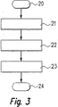
図3は,車両における駆動データを記録するための,本発明に基づく方法に関するフローチャートを示している。記録すべき駆動データの時間的な推移は,図4に参照符号12で示されている。上記方法は,機能ブロック20で開始される。その後機能ブロック21において,データ縮小範囲内で,記録すべき駆動データの推移12が処理される,タイムラスター内のラスターステップ13が求められる。このラスターステップ13は,抽出時間の所定倍の時間,本例においては400×10−6秒である。
【0036】
機能ブロック22において,個々のラスターステップ13内部で,検出された駆動データ推移12のいくつかの特徴的な変化量が求められる。その後,機能ブロック23において,求められた特徴的な変化量が他のメモリ素子7,10に格納される。従って本発明によれば,記録すべき駆動データの推移12の幾つかまたはすべての検出値ではなく,ラスターステップ13内部の特徴的な変化量のみがメモリ素子7,10に格納される。
【0037】
本発明に基づく方法の基礎となるデータ縮小を,図4を用いて詳細に説明する。本実施例にかかり,特徴的な変化量として,ラスターステップ13内部での推移12における検出値の最大値14,最小値15および平均値16が求められる。しかし,任意に他の特徴的な変化量を求めることもできる。ラスターステップ13は,等しい大きさにとることもでき,あるいは検出された駆動データ推移12の他の特徴的な変化量に従って可変にとることも可能である。他の特徴的な変化量として,例えばラスターステップ13内部における推移12の検出値の統計的な変化量,特に標準偏差が考えられる。その場合にこの標準偏差が設定された値を上回らないように,ラスターステップ13を小さく定めることができる。
【0038】
あるいは,ラスターステップ13は,ラスターステップ13内部での推移12における検出値の平均値16に対する,最大値14または最小値15の間隔に従って可変にとることができる。その場合にこの間隔が設定された値を上回らないように,ラスターステップ13を小さく定めることができる。
【図面の簡単な説明】
図面
本発明の他の特徴,実施可能性および利点は,図面に示す本発明の実施例についての以下の説明から明らかにされる。この場合に,記述または図示されたすべての特徴は,それ自体で,あるいは任意の組み合わせにおいて,特許請求項におけるその要約またはその帰属に関係なく,かつ,詳細な説明または図面におけるその表現または図示に関係なく,本発明の対象を形成する。このとき,すでに説明したように,好適な例である車両制御装置や駆動データまたは事故データ記録装置は,一般に,該当する装置または制御素子を備えたコンピュータあるいは制御ユニットとして概念を拡大することができる。つまり,該当するコンピュータプログラムまたは該当するコンピュータプログラム製品が,コンピュータまたは制御ユニットにおけるデータ記憶媒体上で実行されるとき,本発明に基づく方法のステップまたは本発明に基づく方法自体も,実行される。
【図1】 本発明の第1の好ましい実施形態に基づく本発明装置を示している。
【図2】 本発明の第2の好ましい実施形態に基づく本発明装置を示している。
【図3】 好ましい実施形態に基づく本発明方法のフローチャートである。
【図4】 記録すべき情報の推移を示している。[0001]
BACKGROUND OF THE INVENTION 1. Field of the Invention The present invention relates to a method for recording information transition. This information is, in particular, vehicle drive data detected at each set extraction time. By the above method, the detected information is reduced in data, and then the reduced information is stored.
[0002]
The invention further relates to a control element for a control device for open / closed control of predetermined vehicle components or for a vehicle drive data or accident data recording device. Here, the control element is formed in particular as a read only memory (ROM) including EPROM or EEPROM, a random access memory (RAM) including FeRAM, or a flash memory. The control element stores a program that can be executed on a computer, particularly a microprocessor.
[0003]
The present invention also relates to an apparatus for recording information transition. This information is, in particular, vehicle drive data detected at each set extraction time. The apparatus has means for reducing the detection information and means for storing the reduced information.
[0004]
The present invention further includes a computer program and a computer program product comprising program code means that enable recording or data reduction as a superordinate concept described in the independent claim by being executed on a computer or a control unit. About.
[0005]
The detection and recording of drive data in vehicles is becoming increasingly important (see DE 19917464). The drive data is supplied from a suitable sensor and is represented in a normal digital format. This drive data is, for example, the speed of the vehicle, the temperature and drive point of the internal combustion engine of the vehicle, the operation of the accelerator pedal or brake, or the operation of a predetermined vehicle function, in particular the operation of the lighting device or direction lamp (Richungsleuchten). The drive data is recorded for a predetermined time. It is important to reduce the amount of data to be stored because the memory space in the controller for open / closed loop control of a given vehicle component or in the vehicle drive data or accident data recorder is limited It is.
[0006]
The amount of data can be reduced by various methods. First, avoid redundancy in the information to be stored, that is, the same information is stored only once.
[0007]
Furthermore, the amount of data to be stored can be reduced by data reduction. In doing so, information that is not considered important is intentionally omitted and stored. In data reduction, the insignificant information content is intentionally ignored. The original information can be restored from the reduced information with information loss.
[0008]
Finally, the information to be stored can be reduced through data compression. At that time, the number of bits required for storing and transmitting information is reduced. The original information can be restored without loss of information by decompressing the compressed information.
[0009]
For data compression, especially in the field of image data compression and information technology, a very large number of different methods (eg Huffman compression; HYP.LIM: “INTERACTIVE DATA COMPRESSION TUTOR”), SCOOL OF ELECTRICAL AND ELECTRONICS ENGINEERING, see Birmingham, UK, February 1998) and methods for reconstructing time signals based on Shannon's detection theorem (eg, impulse train modulation); V. OPPENHEIM, RW SCHAEFER: “Discrete Time Signal Processing (DISCRETE -TIME SIGNAL PROCESSING) ", PRENTICE HALL, ENGLEWOOD CLIFFS, 1989). However, information loss is always tailored to purpose and depends on the application, so there is no universal way to reduce data.
[0010]
From EP0834146B1, a method and device for reducing the data of detection information in a transplanted medical device is known. Here, the detection information is, for example, the heart rate of the patient. Rather than storing the period between two heartbeats as time data, each time data is associated with a predetermined value that can be recorded in less than the memory space required by the original time data, and stored. It has been proposed to do.
[0011]
From DE 4107198A1, a method and device for recording vehicle drive data is known. In order to reduce the required space of memory space, it has been proposed to delete old information that is no longer needed from the memory. The freed memory space can then be used to store information to be written at that time.
[0012]
A method and apparatus of the kind mentioned at the outset are known, for example, from DE 4344528 A1. It describes a device for storing information in the form of a digital audio signal. The information to be stored is stored in the analog memory as an analog value obtained by digital / analog (D / A) conversion after data reduction. Although data reduction is described in this publication, strictly speaking, it is data compression. As a method for compressing data, adaptive differential pulse code modulation (ADPCM) and linear predictive coding (LPC) have been proposed. The stored information can be extracted from the memory as an audio signal via analog / digital (A / D) reverse conversion.
[0013]
An object of the present invention is to record important digital information, in particular, transition of driving data of a vehicle, with as much memory space as possible.
[0014]
In order to solve this problem, based on the method mentioned at the beginning, within the data reduction range, the transition of the detected information is processed within a time raster that is a predetermined multiple of the extraction time, and within each raster step, It is proposed to obtain at least one characteristic change amount in the transition of the detection information.
[0015]
Advantages of the Invention According to the present invention, there is provided an information recording method capable of remarkably reducing the amount of data to be recorded without losing important information contents in recording a predetermined application, particularly vehicle driving data. Proposed. In the method based on this invention, the characteristic change amount of the information transition detected within each raster step in the time raster is stored as important information contents. As the size of the raster step increases, the amount of data to be stored can be reduced at a high rate. Further, the smaller the characteristic change amount stored in the raster step, the smaller the data amount to be stored.
[0016]
In the method according to the invention, the information to be recorded is reduced to important ones, thereby enabling a significant saving of memory space. After the above data reduction, the amount of data to be stored can be further reduced by using a separate data compression method.
[0017]
The characteristic change amount of the detected information transition that can be used in the method according to the present invention is, for example, the turning point or variance of the detected value transition or the standard deviation of the detected value within each raster step. Here, in a preferred development of the present invention, it is proposed to obtain the maximum value and / or the minimum value of the detection value inside the raster step as the characteristic change amount of the detection information transition. That is, the transition of the detection information within the raster step is represented by an envelope (Hüllkurven) corresponding to the maximum value and / or the minimum value of the detection value.
[0018]
Instead, or in addition, it is conceivable to obtain an average value of detection values inside the raster step as a characteristic change amount of detection information transition. Based on the deviation of the envelope curve from the mean value curve, it is possible to directly read out some data reduction contents. If the curves are far away from each other, the transition within the raster step being processed is shaking violently. In addition, when the curves are arranged close to each other, the transition remains at a substantially constant value.
[0019]
According to a preferred embodiment of the invention, it is proposed that the raster steps are of equal size.
[0020]
According to another embodiment of the present invention, it is proposed that the raster step is variable according to other characteristic changes of information transition detected within the raster step. That is, the magnitude of the raster step changes in a related manner depending on a predetermined signal characteristic described based on a characteristic change amount. This signal characteristic is, for example, a statistical change amount, preferably a standard deviation of an information transition detection value inside the raster step, and the magnitude of the raster step can be changed according to this signal characteristic. Further, the raster step can be set small so that the standard deviation does not exceed the set value.
[0021]
Further, it is proposed that the raster step is variable according to the interval of the maximum value or the minimum value with respect to the average value of the information transition detection value inside the raster step. Preferably, the raster step can be set small so that the interval does not exceed a set value.
[0022]
Of particular importance, the method according to the invention is realized in the form of a control element for open / closed loop control of a given vehicle component or for a vehicle drive data or accident data recording device. That is. In this case, the control element stores a program which can be executed on a computer, in particular a microprocessor, and which is suitable for carrying out the method according to the invention. That is, in such a case, since the present invention is executed by a program stored in the control element, this control element including the program also represents the invention in the same manner as the above method suitable for executing the program. Yes. In particular, an electrical memory medium, such as a read-only memory, a random access memory or a flash memory can be used as the control element.
[0023]
As another solution of the problem in the present invention, based on a device for recording the transition of the detection information of the type mentioned at the beginning, the transition of information detected within a time raster of a predetermined multiple of the extraction time is processed as a data reduction means. , It is proposed to determine at least one characteristic change in the detected information transition within each raster step.
[0024]
According to a preferred development of the invention, it is proposed that the device comprises means for carrying out the method according to the invention.
[0025]
According to a preferred embodiment of the invention, it is proposed that the device is a component of at least one control device for open / closed control of a given vehicle component.
[0026]
Alternatively, it is proposed that the device is a component of a vehicle drive data or accident data recording device.
[0027]
With respect to examples of vehicle control devices and drive data recording devices and accident data recording devices, the method according to the invention can generally be implemented on a computer, through a computer or on a control unit. Thus, in general, the device according to the invention can be regarded as a component of a computer or control unit.
[0028]
In that case, when a corresponding computer program or a corresponding computer program product is implemented on a data storage medium comprising program code means that can be executed on a computer or control unit, it is simultaneously based on the present invention. The method steps or the method itself according to the invention are also carried out. At this time, the data storage medium is preferably a movable data storage medium such as a CD-ROM, DVD, floppy disk, or data storage medium, in addition to the above-described fixedly configured control element. Other optical, magnetic, and electromagnetic memory media can be used when the computer readable or enabled by the means.
[0029]
Other advantages and preferred embodiments are evident from the claims.
[0030]
DESCRIPTION OF THE EMBODIMENTS The method according to the invention is used to record the transition of information. The information to be recorded is in particular vehicle drive data. This drive data is supplied from a suitable sensor and exists in digital form. At this time, the continuous temporal transition of the drive data signal is detected for each set extraction time. The drive data to be recorded are, for example, the speed of the vehicle, the temperature and drive point of the internal combustion engine of the vehicle, the operation of the accelerator pedal or brake, or the operation of a predetermined vehicle function, in particular the operation of the lighting device or direction lamp (Richtungsluchten). .
[0031]
The method according to the invention can be carried out in a control device 1 (see FIG. 1) for open / closed loop control of a given vehicle component or in a vehicle drive data or accident data recording device (see FIG. 2). .) Implemented. A control element 3 is provided in the control device 1, and a program that can be executed on the microprocessor 4 is stored on the control element. As the control element 3, it is possible to use in particular an electrical memory medium, for example a read only memory, a random access memory or a flash memory. The program is used for open / closed loop control of vehicle components. For this purpose, an input signal 5 is supplied to the control device 1, and the input signal is represented by a driving amount of the internal combustion engine or other components in the vehicle, which is measured by a sensor. The control device 1 can generate an output signal 6 and adjust the operation of a predetermined vehicle component in the actuator or driving operation by the output signal.
[0032]
In FIG. 1, on the control element 3 in the control device 1 there is stored another program which can be executed on the microprocessor 4 and which is suitable for carrying out the method according to the invention. ing. The drive data to be recorded is stored in another
[0033]
In the embodiment shown in FIG. 2, the drive data or accident data recording device 2 has a control element 8 and a microprocessor 9. On the control element 8, there is stored another program that can be executed on the microprocessor 9 and is suitable for carrying out the method according to the invention. As the control element 8, an electrical memory medium, for example, a read only memory (ROM) including EPROM or EEPROM, a random access memory (RAM) including FeRAM, or a flash memory can be used. The drive data to be recorded is stored in another memory element 10 in the drive data or accident data recording device 2. Information to be recorded is transmitted from the control device 1 to the drive data or accident data recording device 2 via a suitable data interface 11.
[0034]
Since the memory space in the control device or drive data or accident data recording device is limited, it is important to reduce the amount of data to be stored. Therefore, the detected drive data is first subjected to data reduction. Thereafter, the reduced drive data is subjected to data compression for further reducing the amount of data and stored in another
[0035]
FIG. 3 shows a flow chart for a method according to the invention for recording drive data in a vehicle. The temporal transition of drive data to be recorded is indicated by
[0036]
In the
[0037]
The data reduction that is the basis of the method according to the present invention will be described in detail with reference to FIG. According to the present embodiment, the maximum value 14, the minimum value 15 and the
[0038]
Alternatively, the raster step 13 can be variably set according to the interval of the maximum value 14 or the minimum value 15 with respect to the
[Brief description of the drawings]
Other features, feasibility and advantages of the invention will become apparent from the following description of an embodiment of the invention shown in the drawing. In this case, all features described or illustrated are, in themselves or in any combination, regardless of their summary or attribution in the claims, and their representation or illustration in the detailed description or drawings. Regardless, it forms the subject of the present invention. At this time, as already described, the vehicle control device and the drive data or accident data recording device, which are preferred examples, can generally be expanded as a computer or a control unit equipped with the corresponding device or control element. . In other words, when the relevant computer program or the relevant computer program product is executed on a data storage medium in a computer or control unit, the method steps according to the invention or the method itself according to the invention are also executed.
FIG. 1 shows an inventive apparatus according to a first preferred embodiment of the present invention.
FIG. 2 shows the inventive device according to a second preferred embodiment of the invention.
FIG. 3 is a flowchart of the method of the present invention according to a preferred embodiment.
FIG. 4 shows the transition of information to be recorded.
Claims (14)
前記ラスターステップ(13)の大きさは,ラスターステップ(13)内部で前記検出された情報の推移(12)の少なくとも1つの他の特徴的な変化量に従って可変にとることを特徴とする,検出情報の推移を記録する方法。This is a recording method for reducing the vehicle drive data transition (12), which is information detected at each set extraction time, and further storing the reduced data. The detection information transition (12) is processed in a time raster that is a predetermined multiple of the extraction time, and at least one characteristic change amount (14,) in the detection information transition (12) within each raster step (13). 15 and 16) wherein the recording method is required;
The size of the raster step (13) is characterized by taking the variable in accordance with at least one other characteristic change amount of the transition of the raster step (13) said detected information internally (12), detection A method of recording the transition of information.
マイクロプロセッサ(4,9)上において実行でき,請求項1から7のいずれか1項に記載の方法を実施するためのプログラムが格納されている,制御素子。Read-only memory (ROM), including EPROM or EEPROM, for a control device (1) for open / closed loop control of a given vehicle component or for a vehicle drive data or accident data recording device (2), FeRAM A random access memory (RAM) including a control element (3, 8) comprising a flash memory;
8. A control element, which can be executed on a microprocessor (4, 9) and stores a program for carrying out the method according to any one of claims 1 to 7.
前記ラスターステップ(13)の大きさを,ラスターステップ(13)内部で前記検出された情報の推移(12)の少なくとも1つの他の特徴的な変化量に従って可変にとる,他の手段が含まれていることを特徴とする,検出情報の推移を記録する装置。It has means for reducing the data of the detected information, and means for storing the reduced information for recording the transition (12) of the vehicle drive data, which is information detected for each set extraction time. The data reduction means processes the transition (12) of the detection information within a time raster that is a predetermined multiple of the extraction time, and at least the transition (12) of the detection information within each raster step (13). In the device in which one characteristic change is required;
Wherein the size of the raster step (13) takes the variable in accordance with at least one other characteristic change amount of the transition of the raster step (13) said detected information internally (12), include other means A device that records the transition of detected information.
Applications Claiming Priority (3)
| Application Number | Priority Date | Filing Date | Title |
|---|---|---|---|
| DE10042005.2 | 2000-08-26 | ||
| DE10042005A DE10042005A1 (en) | 2000-08-26 | 2000-08-26 | Method and device for recording scanned information, in particular operating data of a motor vehicle |
| PCT/DE2001/002795 WO2002019267A2 (en) | 2000-08-26 | 2001-07-24 | Method and device for the plotting of scanned information, in particular operating data for a motor vehicle |
Publications (2)
| Publication Number | Publication Date |
|---|---|
| JP2004508622A JP2004508622A (en) | 2004-03-18 |
| JP4890726B2 true JP4890726B2 (en) | 2012-03-07 |
Family
ID=7653903
Family Applications (1)
| Application Number | Title | Priority Date | Filing Date |
|---|---|---|---|
| JP2002524098A Expired - Fee Related JP4890726B2 (en) | 2000-08-26 | 2001-07-24 | Method and apparatus for recording detected information, in particular vehicle drive data |
Country Status (6)
| Country | Link |
|---|---|
| US (1) | US6895311B2 (en) |
| EP (1) | EP1316153B1 (en) |
| JP (1) | JP4890726B2 (en) |
| KR (1) | KR100759619B1 (en) |
| DE (2) | DE10042005A1 (en) |
| WO (1) | WO2002019267A2 (en) |
Families Citing this family (3)
| Publication number | Priority date | Publication date | Assignee | Title |
|---|---|---|---|---|
| US20050093366A1 (en) * | 2003-10-31 | 2005-05-05 | Jerry A. Edwards | Brake monitoring system |
| US8430458B2 (en) | 2005-11-23 | 2013-04-30 | Hopkins Manufacturing Corp. | Towed vehicle braking apparatus |
| DE102018102610A1 (en) * | 2017-12-22 | 2019-06-27 | Endress+Hauser Conducta Gmbh+Co. Kg | Method for detecting signal deviations of a sensor |
Family Cites Families (17)
| Publication number | Priority date | Publication date | Assignee | Title |
|---|---|---|---|---|
| US4258421A (en) * | 1978-02-27 | 1981-03-24 | Rockwell International Corporation | Vehicle monitoring and recording system |
| EP0093190B1 (en) | 1982-05-05 | 1988-03-30 | Arie Visser | Extrema coding signal processing method and apparatus |
| US4603431A (en) * | 1983-03-14 | 1986-07-29 | Ana Tech Corporation | Method and apparatus for vectorizing documents and symbol recognition |
| HU206415B (en) * | 1986-12-29 | 1992-10-28 | Karolyne Otta | Method for recording travel data of a motor vehicle into the memory of electronic tachograph, and device for implementing said method |
| DE3700552B4 (en) * | 1987-01-10 | 2005-06-02 | Robert Bosch Gmbh | Method for outputting route information for land vehicle drivers and information output system |
| GB8910981D0 (en) | 1989-05-12 | 1989-06-28 | Hi Med Instr Limited | Digital waveform encoder and generator |
| JPH0831142B2 (en) | 1990-03-07 | 1996-03-27 | 矢崎総業株式会社 | Digital operation recording device |
| JP3133770B2 (en) * | 1991-01-18 | 2001-02-13 | マツダ株式会社 | Car driving system |
| US5313848A (en) * | 1991-10-18 | 1994-05-24 | Sensitech, Inc. | Disposable electronic monitor device |
| US5983161A (en) * | 1993-08-11 | 1999-11-09 | Lemelson; Jerome H. | GPS vehicle collision avoidance warning and control system and method |
| DE4344528A1 (en) | 1993-12-24 | 1995-06-29 | Blaupunkt Werke Gmbh | Circuit arrangement for storing digital audio signals |
| JPH0898134A (en) * | 1994-09-27 | 1996-04-12 | Nippon Columbia Co Ltd | Data recording and reproducing device |
| JPH08329296A (en) * | 1995-05-31 | 1996-12-13 | Yazaki Corp | Vehicle operation information gathering and analyzing system |
| US5709216A (en) | 1995-06-07 | 1998-01-20 | Sulzer Intermedics, Inc. | Data reduction of sensed values in an implantable medical device through the use of a variable resolution technique |
| KR100204575B1 (en) * | 1996-10-17 | 1999-06-15 | 정선종 | Remote measurement data compression saving and detecting method in satellite controlling system |
| JP2000003466A (en) * | 1998-06-12 | 2000-01-07 | Takashi Nojiri | Digital type tachograph data processing system |
| JP3044025B1 (en) * | 1998-12-09 | 2000-05-22 | 株式会社データ・テック | Operation management system capable of analyzing driving tendency and its constituent devices |
-
2000
- 2000-08-26 DE DE10042005A patent/DE10042005A1/en not_active Withdrawn
-
2001
- 2001-07-24 WO PCT/DE2001/002795 patent/WO2002019267A2/en active IP Right Grant
- 2001-07-24 JP JP2002524098A patent/JP4890726B2/en not_active Expired - Fee Related
- 2001-07-24 DE DE50104031T patent/DE50104031D1/en not_active Expired - Lifetime
- 2001-07-24 US US10/363,445 patent/US6895311B2/en not_active Expired - Fee Related
- 2001-07-24 EP EP01956373A patent/EP1316153B1/en not_active Expired - Lifetime
- 2001-07-24 KR KR1020037002707A patent/KR100759619B1/en not_active IP Right Cessation
Also Published As
| Publication number | Publication date |
|---|---|
| JP2004508622A (en) | 2004-03-18 |
| KR20030038714A (en) | 2003-05-16 |
| US6895311B2 (en) | 2005-05-17 |
| EP1316153A2 (en) | 2003-06-04 |
| US20040024497A1 (en) | 2004-02-05 |
| KR100759619B1 (en) | 2007-09-17 |
| WO2002019267A2 (en) | 2002-03-07 |
| EP1316153B1 (en) | 2004-10-06 |
| DE10042005A1 (en) | 2002-03-07 |
| DE50104031D1 (en) | 2004-11-11 |
| WO2002019267A3 (en) | 2002-08-29 |
Similar Documents
| Publication | Publication Date | Title |
|---|---|---|
| EP1253590A3 (en) | A data storage apparatus that either certifies a recording medium in the background or verifies data written in the recording medium | |
| US20060119536A1 (en) | Encoded image signal conversion method and apparatus | |
| JP4950407B2 (en) | Audio signal compression | |
| JP4890726B2 (en) | Method and apparatus for recording detected information, in particular vehicle drive data | |
| JPH0738120B2 (en) | Audio recording / playback device | |
| TW200304123A (en) | Audio frequency scaling during video trick modes utilizing digital signal processing | |
| EP1519381A3 (en) | A media recording device | |
| CN112313603A (en) | Encoding device, encoding method, decoding device, decoding method, and program | |
| CN116017085A (en) | Method, device, equipment and medium for adding caption and bullet screen in hard disk video | |
| EP1252626B1 (en) | Playback device for compressed audio data | |
| JPH0368399B2 (en) | ||
| US20020013885A1 (en) | Digital recording and reproducing apparatus | |
| KR950013375B1 (en) | Signal compression recording and reproducing restoration method | |
| JP2905215B2 (en) | Recording and playback device | |
| JP2003174624A5 (en) | Data recording apparatus, data recording method and program for recording data | |
| JPH10126745A (en) | Variable speed reproduced image expanding device | |
| KR101015408B1 (en) | Device and method for storing necessary information for transportation | |
| KR930002585B1 (en) | Voiceless period compression and decompression method | |
| JP4529859B2 (en) | Audio playback device | |
| EP1120978A1 (en) | Apparatus capable of encoding audio/video data with decreased buffer capacity | |
| JP3498319B2 (en) | Automatic performance device | |
| KR20230033526A (en) | Apparatus for generating driving sound for vehicle, and method thereof | |
| US10411730B2 (en) | Data compression system for storing data from an automated vehicle | |
| JP4470002B2 (en) | Data storage | |
| JPH08335099A (en) | Recording device and reproducing device |
Legal Events
| Date | Code | Title | Description |
|---|---|---|---|
| A621 | Written request for application examination |
Free format text: JAPANESE INTERMEDIATE CODE: A621 Effective date: 20080724 |
|
| A131 | Notification of reasons for refusal |
Free format text: JAPANESE INTERMEDIATE CODE: A131 Effective date: 20110215 |
|
| A601 | Written request for extension of time |
Free format text: JAPANESE INTERMEDIATE CODE: A601 Effective date: 20110516 |
|
| A602 | Written permission of extension of time |
Free format text: JAPANESE INTERMEDIATE CODE: A602 Effective date: 20110525 |
|
| A521 | Written amendment |
Free format text: JAPANESE INTERMEDIATE CODE: A523 Effective date: 20110615 |
|
| TRDD | Decision of grant or rejection written | ||
| A01 | Written decision to grant a patent or to grant a registration (utility model) |
Free format text: JAPANESE INTERMEDIATE CODE: A01 Effective date: 20111115 |
|
| A01 | Written decision to grant a patent or to grant a registration (utility model) |
Free format text: JAPANESE INTERMEDIATE CODE: A01 |
|
| A61 | First payment of annual fees (during grant procedure) |
Free format text: JAPANESE INTERMEDIATE CODE: A61 Effective date: 20111215 |
|
| R150 | Certificate of patent or registration of utility model |
Free format text: JAPANESE INTERMEDIATE CODE: R150 |
|
| FPAY | Renewal fee payment (event date is renewal date of database) |
Free format text: PAYMENT UNTIL: 20141222 Year of fee payment: 3 |
|
| R250 | Receipt of annual fees |
Free format text: JAPANESE INTERMEDIATE CODE: R250 |
|
| LAPS | Cancellation because of no payment of annual fees |