JP4889207B2 - Fuel cell power generator - Google Patents
Fuel cell power generator Download PDFInfo
- Publication number
- JP4889207B2 JP4889207B2 JP2004201407A JP2004201407A JP4889207B2 JP 4889207 B2 JP4889207 B2 JP 4889207B2 JP 2004201407 A JP2004201407 A JP 2004201407A JP 2004201407 A JP2004201407 A JP 2004201407A JP 4889207 B2 JP4889207 B2 JP 4889207B2
- Authority
- JP
- Japan
- Prior art keywords
- gas
- water
- fuel cell
- burner
- combustion
- Prior art date
- Legal status (The legal status is an assumption and is not a legal conclusion. Google has not performed a legal analysis and makes no representation as to the accuracy of the status listed.)
- Active
Links
Images


Classifications
-
- Y—GENERAL TAGGING OF NEW TECHNOLOGICAL DEVELOPMENTS; GENERAL TAGGING OF CROSS-SECTIONAL TECHNOLOGIES SPANNING OVER SEVERAL SECTIONS OF THE IPC; TECHNICAL SUBJECTS COVERED BY FORMER USPC CROSS-REFERENCE ART COLLECTIONS [XRACs] AND DIGESTS
- Y02—TECHNOLOGIES OR APPLICATIONS FOR MITIGATION OR ADAPTATION AGAINST CLIMATE CHANGE
- Y02E—REDUCTION OF GREENHOUSE GAS [GHG] EMISSIONS, RELATED TO ENERGY GENERATION, TRANSMISSION OR DISTRIBUTION
- Y02E60/00—Enabling technologies; Technologies with a potential or indirect contribution to GHG emissions mitigation
- Y02E60/30—Hydrogen technology
- Y02E60/50—Fuel cells
Description
本発明は、水素を含む改質ガスを用いて発電する燃料電池発電装置に関する。 The present invention relates to a fuel cell power generator that generates power using a reformed gas containing hydrogen.
水素生成器は主として、原料ガス(炭化水素)と水から水蒸気改質反応により水素を含む改質ガスを生成するための改質触媒を充填した改質触媒体と、この改質触媒体を熱交換により加熱するための燃焼ガスを生成するバーナと、改質触媒体によって生成される改質ガス中に含有する一酸化炭素ガスを除去するCO除去装置と、によって構成されている。 The hydrogen generator mainly includes a reforming catalyst body filled with a reforming catalyst for generating a reformed gas containing hydrogen from a raw material gas (hydrocarbon) and water by a steam reforming reaction, and heats the reforming catalyst body. It comprises a burner that generates combustion gas for heating by exchange, and a CO removal device that removes carbon monoxide gas contained in the reformed gas generated by the reforming catalyst body.
CO除去装置により一酸化炭素ガスを除去した改質ガスは燃料電池のアノードに供給される。そして、燃料電池は、改質ガス(水素ガス)を消費して発電する。 The reformed gas from which the carbon monoxide gas has been removed by the CO removing device is supplied to the anode of the fuel cell. The fuel cell consumes the reformed gas (hydrogen gas) to generate power.
ここで、燃焼ガスを生成する上記バーナの燃料ガスとして、燃料電池の内部で消費されずに、燃料電池から排出された残留水素を含むオフガスが使用されている。 Here, off-gas containing residual hydrogen discharged from the fuel cell without being consumed inside the fuel cell is used as the fuel gas of the burner that generates combustion gas.
このようなオフガスには通常、残留水素の他に飽和状態にある水蒸気が含まれる。このため、燃料電池とバーナとの間のオフガスを流す経路は断熱され、これによりオフガス中の水蒸気が凝縮することを極力防止している。 Such off-gas usually contains saturated water vapor in addition to residual hydrogen. For this reason, the path through which the off gas flows between the fuel cell and the burner is insulated, thereby preventing the water vapor in the off gas from condensing as much as possible.
しかし、このような断熱処理がオフガス経路に如何に施されたとしても、オフガスの温度(約70〜80℃)は、雰囲気温度よりも高温なため、オフガスの外部雰囲気中への放熱は避け難く、これにより飽和状態にある水蒸気の一部は、必然的に凝縮する。水蒸気の凝縮によって発生した微細な水滴は、オフガス中を浮遊しつつオフガスの流れに同伴してバーナに導かれる。 However, no matter how such a heat insulation treatment is applied to the off-gas route, the off-gas temperature (about 70 to 80 ° C.) is higher than the ambient temperature, so it is difficult to avoid the heat radiation of the off-gas into the external atmosphere. This inevitably condenses some of the saturated water vapor. The fine water droplets generated by the condensation of the water vapor are guided to the burner along with the flow of the off gas while floating in the off gas.
一方、バーナに水滴が混入すれば、水滴を蒸発するための蒸発潜熱分の熱量がバーナによって消費されるため、水素生成器の熱効率の低下を招く。加えて、バーナにおける燃料ガスの燃焼状態は、水滴の存在に起因して不安定になり易く、バーナの火炎が失火する可能性もある。 On the other hand, if water droplets are mixed in the burner, the amount of heat for the latent heat of evaporation for evaporating the water droplets is consumed by the burner, leading to a decrease in the thermal efficiency of the hydrogen generator. In addition, the combustion state of the fuel gas in the burner tends to become unstable due to the presence of water droplets, and the flame of the burner may be misfired.
そこで、オフガスに浮遊する水滴のバーナ(燃焼器)への混入を防止して、バーナの安定な燃焼を可能にする装置が知られている(例えば、従来例としての特許文献1参照)。
In view of this, there is known a device that prevents water droplets floating in off-gas from entering a burner (combustor) and enables stable combustion of the burner (see, for example,
この装置は、高温のオフガスをバーナに供給する前に冷却するため、オフガスの水蒸気凝縮分離を事前に促進でき、これによってバーナの燃焼状態が不安定化することを防止するものである。
しかし、上記の従来例に示した装置では、熱交換部(オフガス冷却部)において発生した微細な水滴を完全に取り除くことは困難である。また、この熱交換部を通過したオフガスの水蒸気は、依然として冷却後の温度に対して飽和状態にあり、熱交換部とバーナとの間の経路を流れるオフガスの外部雰囲気への放熱等によってその温度が下がれば、飽和状態にある水蒸気を凝縮して水滴が再び発生する。 However, in the apparatus shown in the above conventional example, it is difficult to completely remove fine water droplets generated in the heat exchange part (off-gas cooling part). Further, the off-gas water vapor that has passed through the heat exchange section is still in a saturated state with respect to the temperature after cooling, and the temperature of the off-gas steam is radiated to the external atmosphere of the off-gas flowing through the path between the heat exchange section and the burner. When the water pressure drops, water vapor in a saturated state is condensed and water droplets are generated again.
本発明は、斯かる事情に鑑みてなされたものであり、その目的は、オフガスに含有する水蒸気をこのオフガスから適切に分離しかつ除去して、バーナに導いたオフガスの水滴生成を防止する燃料電池発電装置を提供することにある。 The present invention has been made in view of such circumstances, and an object of the present invention is to appropriately separate and remove the water vapor contained in the off gas from the off gas, thereby preventing the generation of water droplets of the off gas led to the burner. The object is to provide a battery power generator.
本発明に係る燃料電池発電装置は、原料ガスと水蒸気から水素を含む改質ガスを生成する改質触媒体と、前記改質ガスを消費して発電する燃料電池と、前記燃料電池から送出する水素を含むオフガスを燃料ガスとして、前記改質触媒体を加熱するための燃焼ガスを生成するバーナと、前記バーナにより生成した燃焼ガスを流す経路を覆っている断熱材と、水を蒸発させ、前記水蒸気を生成する水蒸発部と、を備えており、前記オフガスから水蒸気が分離され、前記分離された水蒸気が凝集水として外部に除去され、かつ、前記水蒸気が分離されたオフガスの前記バーナへの供給配管が、前記断熱材の内側に配置され、前記断熱材の内側において前記オフガスが、前記水蒸発部と熱交換した後の前記燃焼ガスとの熱交換により加熱されるように構成されている。
また、本発明に係る燃料電池発電装置は、原料ガスと水蒸気から水素を含む改質ガスを生成する改質触媒体と、前記改質ガスを消費して発電する燃料電池と、
前記燃料電池から送出する水素を含むオフガスを燃料ガスとして、前記改質触媒体を加熱するための燃焼ガスを生成するバーナと、前記バーナにより生成した燃焼ガスを流す経路を覆っている断熱材と、水を蒸発させ、前記水蒸気を生成する水蒸発部と、を備えており、前記オフガスから水蒸気が分離され、前記分離された水蒸気が凝集水として外部に除去され、かつ、前記水蒸気が分離されたオフガスの前記バーナへの供給配管が、前記断熱材の内側に配置され、前記断熱材の内側において前記オフガスが、前記燃焼ガスとの熱交換により加熱され、前記燃焼ガスが前記水蒸発部内の水および前記オフガスと同時に熱交換するように構成されている。
このように、本発明では、オフガスの水蒸気を適切に分離した後、オフガスのバーナへの供給配管においてオフガスを熱交換加熱している。このため、オフガスに同伴する水滴によりバーナ内の燃料ガスの燃焼状態を不安定にするという従来の問題に適切に対処できる。
A fuel cell power generator according to the present invention includes a reforming catalyst body that generates a reformed gas containing hydrogen from raw material gas and water vapor, a fuel cell that consumes the reformed gas to generate power, and a fuel cell that delivers the reformed gas. Using an off gas containing hydrogen as a fuel gas, a burner that generates combustion gas for heating the reforming catalyst body, a heat insulating material that covers a path through which the combustion gas generated by the burner flows, water is evaporated, A water evaporation section that generates the water vapor, the water vapor is separated from the off-gas, the separated water vapor is removed to the outside as condensed water, and the off-gas from which the water vapor is separated to the burner supply pipe is disposed inside the heat insulating material, such that the off-gas inside of the heat insulating material is heated by heat exchange with the combustion gas after the heat exchange the water evaporation unit It has been made.
A fuel cell power generator according to the present invention includes a reforming catalyst body that generates a reformed gas containing hydrogen from raw material gas and water vapor, a fuel cell that consumes the reformed gas to generate power,
Burner for generating combustion gas for heating the reforming catalyst body using off-gas containing hydrogen delivered from the fuel cell as fuel gas, and a heat insulating material covering a path for flowing the combustion gas generated by the burner; A water evaporation section that evaporates water and generates the water vapor, wherein the water vapor is separated from the off-gas, the separated water vapor is removed to the outside as condensed water, and the water vapor is separated. A pipe for supplying off-gas to the burner is disposed inside the heat insulating material, and the off-gas is heated by heat exchange with the combustion gas inside the heat insulating material, and the combustion gas is disposed in the water evaporation section. Heat exchange is performed simultaneously with water and the off-gas.
Thus, in the present invention, after the off-gas water vapor is appropriately separated, the off-gas is heat-exchanged and heated in the supply pipe to the off-gas burner. For this reason, the conventional problem of making the combustion state of the fuel gas in the burner unstable due to water droplets accompanying the off gas can be appropriately dealt with.
また、本発明に係る燃料電池発電装置は、前記水蒸発部の外周に燃焼ガス流路が配設され、前記燃焼ガス流路の外周に前記供給配管が配設されてもよい。In the fuel cell power generator according to the present invention, a combustion gas flow path may be disposed on the outer periphery of the water evaporation section, and the supply pipe may be disposed on the outer periphery of the combustion gas flow path.
本発明によれば、オフガスに含有する水蒸気をこのオフガスから適切に分離しかつ除去して、バーナに導いたオフガスの水滴生成を防止する燃料電池発電装置が得られる。 According to the present invention, it is possible to obtain a fuel cell power generator that appropriately separates and removes water vapor contained in the off gas from the off gas to prevent generation of water droplets of the off gas guided to the burner.
本最良の形態の特徴は、燃料電池から送出される残留水素を含むオフガスを冷却することによりオフガスに含有する水蒸気の凝縮分離を促進し、水蒸気を凝縮水して外部に除去すると共に、水蒸気を分離したオフガスの温度を露点よりも充分に高めに加熱してオフガスに同伴しようとする微細な水滴を完全に蒸発させることにある。なおここで、オフガスのバーナへの供給途中においてオフガスの外部雰囲気への放熱が発生しても、バーナに到達したオフガスの温度が、露点温度未満にまで低下しないようにオフガスが充分に加熱されている。 The feature of this best mode is that the off-gas containing residual hydrogen delivered from the fuel cell is cooled to promote the condensation and separation of the water vapor contained in the off-gas, and the water vapor is condensed and removed to the outside. The temperature of the separated off gas is heated sufficiently higher than the dew point to completely evaporate fine water droplets that are to be accompanied by the off gas. It should be noted that the offgas is sufficiently heated so that the temperature of the offgas that reaches the burner does not decrease below the dew point temperature even if heat is released to the external atmosphere during the supply of the offgas to the burner. Yes.
以下、本発明の実施の形態について、図面を参照しながら詳しく説明する。 Hereinafter, embodiments of the present invention will be described in detail with reference to the drawings.
(参考の形態1)
図1は、参考の形態1に係る燃料電池発電装置の構成を示すブロック図である。
( Reference form 1)
FIG. 1 is a block diagram showing a configuration of a fuel cell power generator according to
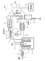
燃料電池発電装置100における改質ガスおよび酸化剤ガスの供給系統は主として、原料ガス(都市ガス)と水蒸気とを用いて改質反応により水素を含む改質ガスを生成するための改質触媒体5を有する改質器4と、改質器4に都市ガスを供給するための原料供給部としての都市ガス供給配管1と、改質器4に水を供給するための水供給部としての水供給配管2と、水供給配管2を流れる水を蒸発させるための水蒸発器3と、改質触媒体5を加熱するための燃焼ガスを、燃焼用空気供給配管17から導かれた空気とオフガス(後ほど説明)との混合ガスを燃焼して生成するバーナ6と、改質器4によって生成した改質ガスを下流側に導く改質ガス配管7と、改質器4から送られた改質ガス中に含まれる一酸化炭素(CO)ガスを除去するCO除去装置8と、酸化剤ガス(空気)をカソード9cで消費しかつ改質ガス(水素ガス)をアノード9aで消費して発電する燃料電池9と、酸化剤ガスを酸化剤ガス供給手段(図示せず)から燃料電池9のカソード9cに導く空気供給配管10−1と、改質ガスをCO除去装置8から燃料電池9のアノードに導く改質ガス供給配管10−2と、によって構成されている。
The reformed gas and oxidant gas supply system in the fuel cell
また、燃料電池発電装置100におけるオフガスの処理系統は主として、燃料電池9の内部で消費されなかった残留水素ガスを含む約70〜80℃のオフガスをアノード9aから下流側に導くオフガス配管11と、オフガス配管11に接続されオフガスの温度を空冷ファン13から送風される空気(冷媒)との熱交換により冷却するオフガス冷却器(冷却用熱交換部)12と、オフガス中に存在する水蒸気を凝縮して液化して得られた凝集水19を溜めると共に、この凝集水19を水排出弁32の開閉動作により外部に排出し除去する凝集水タンク14と、凝集水タンク14から送出されたオフガスをバーナ16に導く燃料配管16と、バーナ6により生成した燃焼ガスを改質器4から外部に導く燃焼ガス配管18と、燃料配管16と燃焼ガス配管18とに接続して、燃焼ガス配管18を流れる燃焼ガスとの熱交換により燃料配管を流れるオフガスを加熱するオフガス加熱器(加熱用熱交換部)15と、オフガス加熱器15の上流側でかつ凝集水タンク14の下流側(出口近傍)である点におけるオフガスの温度を測定する第一の温度測定部30と、オフガス加熱器15を通過したバーナ6に供給する前のオフガスの温度を測定する第二の温度測定部31と、第一および第二の温度測定部30、31の検知温度に基づいてオフガスや燃焼ガスの流量を流量調整弁(図示せず)により制御する制御装置33と、によって構成されている。なお、図示されていないが、制御装置33は、所定の検知信号(ガス温度やガス流量)に基づいて燃料電池発電装置100の動作も適切に制御している。
The off-gas treatment system in the fuel cell
また、燃料電池9から送出する水素を含むオフガスから水蒸気を分離すると共に、分離した水蒸気を凝集して外部に除去する水分離除去部50は、オフガス冷却器12と、空冷ファン13と、凝集水タンク14と、により構成されている。
The water separation /
ここで、オフガス配管11に接続したオフガス冷却器12(例えば、オフガスを通流する配管等)を空冷ファン13から送風される空気により冷やし、これによりオフガス冷却器12を流れるオフガスの温度を空気との熱交換により冷却する。このようなオフガス冷却器12のオフガス放熱促進効果により、オフガスの温度が所定の温度まで速やかに下がり、オフガス中に含有する水蒸気が水滴としてオフガス中に凝縮した後、この水滴が集まって凝集水タンク14の内部に凝集水19が溜まる。
Here, the offgas cooler 12 (for example, a pipe through which the offgas flows) connected to the
次に、以上のように構成された燃料電池発電装置100のオフガス処理系統の動作を、図1を参照して説明する。
Next, the operation of the off-gas processing system of the fuel cell
なお、燃料電池9の発電や燃料電池9に対するガス供給等は、既存技術により実行され、ここでは、このような動作の説明は省略する。
The power generation of the
燃料電池9のアノード9aから送出され、約70〜80℃のオフガスには、燃料電池9において未消費の水素ガスおよび改質器4において水素ガス生成の際に生じる二酸化炭素ガス並びに飽和状態にある水蒸気等が含有されている。
The off-gas of about 70 to 80 ° C. sent from the
このようなオフガスは、オフガス配管11を通ってオフガス冷却器12に供給され、このオフガス冷却器12において空冷ファン13から送風される空気との熱交換により約50〜60℃にまで空冷される。ここで、オフガスから水蒸気を分離した凝集水タンク14の出口近傍におけるオフガスは、約50〜60℃の温度に相当する飽和水蒸気を含んでいる。
Such off-gas is supplied to the off-
なおこの際、オフガスに存在する水蒸気が凝縮して液化され、これによりオフガスから水蒸気を分離して得られる凝集水19が凝集水タンク14に溜まる。
At this time, the water vapor present in the off-gas is condensed and liquefied, and thereby the condensed
その後、オフガスは、オフガス加熱器(加熱用熱交換部)15に供給され、このオフガス加熱器15において燃焼ガス配管18を流れる高温の燃焼ガスと熱交換することにより80〜90℃程度にまで加熱される。これにより、オフガスは、露点温度(約50〜60℃)よりも充分に温度を高めたガスになる。そして、この状態でオフガスが燃料配管16を通過してバーナ6に供給される。
Thereafter, the off-gas is supplied to an off-gas heater (heating heat exchanging section) 15, and is heated to about 80 to 90 ° C. by exchanging heat with the high-temperature combustion gas flowing through the
凝集水タンク14の出口近傍のオフガス温度が、第一の温度測定部30により検知される一方、オフガス加熱器15を通過したバーナ6に供給する前のオフガス温度が、第二の温度測定部31により検知される。また、これらの検知温度が制御装置33により監視され、適切なオフガス温度を維持するように制御装置33は制御している。例えば、オフガス加熱器15を通過した加熱後のオフガスの温度が、何らかの要因(オフガス/燃焼ガスの温度や流量の変化)によりシフトした場合、その目標値に速やかに到達できるように、制御装置33によりオフガスおよび/または燃焼ガスの流量が適切に制御されている。
The off-gas temperature in the vicinity of the outlet of the
バーナ6の内部に導かれたオフガスは、燃焼用空気供給配管17を流れてバーナ6の内部に流入した空気と混合した後、この混合ガスがバーナ6の内部で燃焼して高温の燃焼ガスが生成される。その後、熱交換により改質触媒体5を加熱した燃焼ガスは、燃焼ガス配管18を通って、既に説明したようにオフガス加熱器15のオフガス加熱源として利用されて大気に放出される。
The off-gas introduced into the
なお、凝集水タンク14に溜まった凝縮水19を、改質器4に供給される水として利用することも可能である(図6参照)。
The
以上に説明した燃料電池発電装置100のオフガス処理系統の動作によれば、水分離除去部50によりオフガスの水蒸気を適切に分離した後、これをオフガス加熱器15により熱交換加熱したため、オフガスに同伴する水滴を確実に蒸発できる。
According to the operation of the off-gas treatment system of the fuel cell
更に、オフガスをその露点温度よりも充分に高めに加熱することにより、オフガス加熱器15を通過した燃料配管16を流れるオフガスが、バーナ6に導かれる間に放熱しても、オフガス温度がその露点未満にまで低下することを適切に防止できる。
Further, by heating the off gas sufficiently higher than its dew point temperature, even if the off gas flowing through the
こうして、オフガスに同伴する水滴によりバーナ6における燃料ガスの燃焼状態を不安定にするという従来の問題に適切に対処できる燃料電池発電装置100が得られる。
In this way, the fuel cell
なお、上述の参考の形態1においては、オフガス加熱器15を通過したオフガスの温度例として80〜90℃が示されているが、これは装置構成により変化するため、このような温度範囲に、オフガスの望ましい加熱条件が限定されることを意味しない。
In the above-mentioned
要するに、ここでの加熱条件としては、オフガスがバーナ6に到達した時点において、オフガスの放熱等によりオフガス温度がその露点未満に到達しないように加熱するという趣旨である。もっとも、オフガス加熱器15を通過したバーナ6に供給する前のオフガスの温度を、少なくとも凝集水タンク14の下流側(出口近傍)におけるオフガスの温度以上に加熱する必要がある。
In short, the heating condition here is that when the off gas reaches the
〔水分離除去部50の変形例〕
図1に示すように、空冷ファン13を使用したオフガス冷却器12と凝集水タンク14とを別個に配置しても良いが、これの変形例として、図2および図3に示すように、オフガス冷却器に相当する冷却用熱交換部を凝集水タンク14と連結して両者を一体的に配置することも可能である。これにより、燃料電池発電装置100の水分離除去部50の構成を簡素化できる。
[Modification of Water Separation and Removal Unit 50]
As shown in FIG. 1, the off-
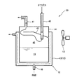
図2および図3は共に、冷却用熱交換部を連結した凝集水タンクを有する水分離除去部の内部構成例を示す断面図である。 2 and 3 are both cross-sectional views showing an example of the internal configuration of a water separation / removal unit having a condensed water tank connected with a cooling heat exchange unit.
図2に示すように、水分離除去部50は、蓋部と底部を有してオフガスから水蒸気を分離して得られる凝集水19を溜める筒状の凝集水タンク14と、凝集水タンク14の内部にオフガスを導くように、オフガス配管11(図1参照)に接続して凝集水タンク14の蓋部に設けられたオフガス入口配管40と、凝集水タンク14の内部を通過したオフガスをその外部に導くように、燃料配管16(図1参照)に接続して凝集水タンク14の蓋部に設けられたオフガス出口配管41と、オフガス出入口配管40、41の近傍の凝集水タンク14の内部に配置され、オフガスの流れを遮ってオフガスの流速を減速させることによってオフガス中に含有する水滴を滴下させ易くする邪魔板42と、凝集水タンク14の内部に溜まった凝集水19を定期的に外部に導くために、水排出弁32(図1参照)に接続して凝集水タンク14の底部に設けられた水出口配管(図示せず)と、により構成されている。
As shown in FIG. 2, the water separation /
なおここで、凝集水タンク14の略上半分の内部にはオフガスが通過する通過領域45(凝集水タンク14の内部のオフガスが流れる経路)が形成されている。
Here, a passage region 45 (a path through which the off gas inside the
また、冷媒入口部46から導かれた冷媒(液体や気体)が凝集水タンク14の外周面に沿って流れるように、冷媒路43(冷却用熱交換部)が、凝集水タンク14の外周面との間で冷媒を流す空間を形成するように配置され、これにより、オフガスが通過領域45を流れる間に、冷媒路43を流れる冷媒により冷えた凝集水タンク14の外周面にオフガスが接触してオフガスの温度が下がる。すなわち、冷媒路43の内部を流れる冷媒との熱交換によりオフガスが冷却される。
Further, the refrigerant path 43 (cooling heat exchanging portion) is arranged on the outer peripheral surface of the
もしくは、図2に示すように、空冷ファン13から凝集水タンク14の外周面に向けて送風される空気(冷媒)との熱交換を併用するよって、オフガスの温度をより速やかに下げるように構成しても良い。
Alternatively, as shown in FIG. 2, the temperature of the off gas can be lowered more quickly by using heat exchange with air (refrigerant) blown from the
このような冷却路43のオフガス放熱促進効果により、オフガスの温度が所定の温度まで迅速に下がり、オフガス中に含有する水蒸気が水滴としてオフガス中に凝縮した後、この水滴が集まって凝集水タンク14の内部に凝集水19が溜まる。
Due to the off-gas heat dissipation promotion effect of the cooling
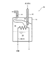
また、図3に示すように、水分離除去部50の他の例としては、冷媒を充填した配管(冷却用熱交換部)48が、外部から凝集水タンク14の内部の通過領域45に達して、かつ通過領域45から外部に延びるように、略コの字状に配置されている。こうして、オフガスが通過領域45を流れる間に、冷媒を流す配管48にオフガスが接触することによって、この冷媒との熱交換によりオフガスが冷却される。なお、配管48以外の図3に示す水分離除去部50の構成は、図2に示すものと同じであるため、両者に共通する構成の説明は省略する。
As another example of the water separation /
(参考の形態2)
図4は、参考の形態2に係る燃料電池発電装置の構成を示すブロック図である。
( Reference form 2)
FIG. 4 is a block diagram showing the configuration of the fuel cell power generator according to
図4では、図1と同一の構成要素に同じ符号を記している。 In FIG. 4, the same components as those in FIG.
図1と図4(a)との比較から理解されるとおり、参考の形態2に係る燃料電池発電装置110の構成が、上述の参考の形態1に係る燃料電池発電装置100の構成と相違する点は、水蒸発部36を改質器4の内部の燃焼ガス流路35に配置したことと、オフガスのバーナ6への供給配管としてのオフガス加熱器20を改質器4の燃焼ガス流路35に配置したことにある。水蒸発部36を改質器4の燃焼ガス流路35に配置したことにより、燃料電池発電装置100の熱効率の向上が図られる。また、オフガス加熱器20を改質器4の燃焼ガス流路35に配置したことにより、オフガス加熱器20の構成の簡素化が図られる。
As understood from the comparison between FIG. 1 and FIG. 4A, the configuration of the fuel cell
ここで、図4(b)を参照して、水蒸発部36とオフガス加熱器20の構成を説明する。なお、これらの構成以外の参考の形態1に共通する構成の説明は省略する。
Here, with reference to FIG.4 (b), the structure of the
図4(b)は、参考の形態2に係る改質器の燃焼ガス流路における水蒸発部とオフガス加熱器の配置構成の模式図である。
FIG. 4B is a schematic diagram of the arrangement configuration of the water evaporation section and the off-gas heater in the combustion gas flow path of the reformer according to
外壁61により囲まれた改質器4の内部には、バーナ6(図4(a)参照)に接続してバーナ6により生成した燃焼ガスを下流に導く筒状の燃焼筒60が配置され、これにより、燃料筒60と外壁61との間に筒状の燃焼ガス流路35が形成されている。そして、燃焼筒60の外周面近傍には筒状の水蒸発部36が配置される一方、オフガス加熱器20の一部が、燃焼ガス流路35の内部に延びそこを通過するように配置されている。なお、オフガス加熱器20と外壁61との接続箇所は、燃焼ガスが漏れないように適宜の方法によりシールされている。
Inside the reformer 4 surrounded by the
このような燃焼ガス流路35において、図4(b)の二点鎖線で示すように、燃焼筒60から流出する燃焼ガスが燃焼筒60と水蒸発部36との間の筒状の空間を通った後、その向きを180°変えて、この燃焼ガスが、水蒸発部36と外壁61との間の筒状の空間を通過して燃焼ガス配管18に導かれる。
In such a combustion
こうして、燃焼ガスが燃焼ガス流路35を流れる間に、その内部において水蒸発部36を図4(b)に示す一点鎖線のように流れる水(正確には図4(a)に示すように、都市ガス供給配管1を流れる都市ガスと水供給配管2を流れる水とが混ざり合ったもの)が、燃焼ガスとの熱交換により加熱されると共に、オフガス加熱器20を図4(b)に示す矢印のように流れるオフガスが、燃焼ガスとの熱交換により加熱される。
Thus, while the combustion gas flows through the combustion
(実施の形態)
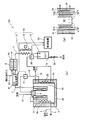
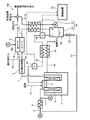
図5は、本発明の実施の形態に係る燃料電池発電装置の構成を示すブロック図である。
(In the form state of implementation)
Figure 5 is a block diagram showing a configuration of a fuel cell system according to the shape condition of the present invention.
図5では、図4と同一の構成要素に同じ符号を記している。 In FIG. 5, the same components as those in FIG. 4 are denoted by the same reference numerals.
図5と図4との比較から理解されるとおり、実施の形態に係る燃料電池発電装置120の構成が、上述の参考の形態2に係る燃料電池発電装置110の構成と相違する点は、改質器4の外壁61の周囲に断熱材62を配置したことと、この断熱材62の内側に、オフガスのバーナ6への供給配管としてのオフガス加熱器20を配置したことにある(正確には、断熱材62に凹部が形成され、この凹部にオフガス加熱器20を収めたうえで、オフガス加熱部22を覆って別の断熱材が被せられている。)。断熱材62を配置したことにより、改質器4の燃焼ガス流路35を流れる燃焼ガスの放熱を適正に抑制できると共に、断熱材62の内側にオフガス加熱器20を配置するという簡易な構成でオフガスと燃焼ガスとの熱交換を行うことが可能になる。すなわち、オフガス加熱器2と断熱材62との接続箇所にシール処置等を行うことなく、オフガス加熱器を断熱材62の内側に配置可能である。
As will be appreciated from a comparison of FIGS. 5 and 4, is that the structure of the
ここで、図5(b)を参照して、水蒸発部36とオフガス加熱器20の構成を説明する。
Here, with reference to FIG.5 (b), the structure of the
図5(b)は、実施の形態に係る改質器の燃焼ガス流路における水蒸発部とオフガス加熱器の配置構成の模式図である。 5 (b) is a schematic view of the arrangement of the water evaporation unit and off gas heater in the combustion gas flow passage of the reformer according to the shape condition of the embodiment.
参考の形態2と同様に、燃料筒60と改質器4の外壁61との間に筒状の燃焼ガス流路35が形成されている。そして、この外壁61に接触してこれを覆うように断熱材62が配置され、オフガス加熱器20の一部が、この断熱材62の内側に延びそこを通過するように配置されている。
Similarly to
なお参考の形態2と同様に、燃焼筒60の外周面近傍には筒状の水蒸発部36が配置されている。
Similar to the
このような燃焼ガス流路35において、図5(b)の二点鎖線に示すように、燃焼筒60から流出する燃焼ガスが、燃焼筒60と水蒸発部36との間の筒状の空間を通った後、その向きを180°変えて、この燃焼ガスが、水蒸発部36と外壁61との間の筒状の空間を通過して燃焼ガス配管18に導かれる。
In such a combustion
こうして、燃焼ガスが燃焼ガス流路35を流れる間に、その内部において水蒸発部36を図5(b)に示す一点鎖線のように流れる水(正確には図5(a)に示すように、都市ガス供給配管1を流れる都市ガスと水供給配管2を流れる水とが混ざり合ったもの)が、燃焼ガスとの熱交換により加熱されると共に、オフガス加熱器20を図5(b)に示す矢印のように流れるオフガスが、燃焼ガスとの熱交換により加熱される。
Thus, while the combustion gas flows through the combustion
(参考の形態3)
図6は、参考の形態3に係る燃料電池発電装置の構成を示すブロック図である。
( Reference form 3 )
FIG. 6 is a block diagram showing the configuration of the fuel cell power generator according to
図6では、図1と同一の構成要素に同じ符号を記している。 In FIG. 6, the same components as those in FIG. 1 are denoted by the same reference numerals.
図1と図6との比較から理解されるとおり、参考の形態3に係る燃料電池発電装置130の構成が、上述の参考の形態1に係る燃料電池発電装置100の構成と相違する点は、図1に示した空冷ファン13を使用することなく、オフガスを流すオフガス通路11−1と冷媒を流す冷媒通路11−2とにより接続されるオフガス冷却器(冷却用熱交換部)21を設けたことと、水排出弁32を水蒸発部3に連結したことにある。また、燃料電池9から送出する水素を含むオフガスから水蒸気を分離すると共に、分離した水蒸気を凝集して外部に除去する水分離除去部50は、オフガス冷却器50と、凝集水タンク14と、により構成されている。
As understood from the comparison between FIG. 1 and FIG. 6, the difference between the configuration of the fuel cell
これにより、空冷ファン13を無くして部品点数を削減しつつ、オフガス通路11−1を流れるオフガスが、冷媒通路11−2を流れる冷媒とオフガス冷却器21を介して熱交換することにより冷却される。
Accordingly, the off-gas flowing through the off-gas passage 11-1 is cooled by exchanging heat with the refrigerant flowing through the refrigerant passage 11-2 via the off-
なお、参考の形態3における参考の形態1と共通する構成の説明は省略する。
Note that the omitted explanation common to
ここで、図6に示すように、オフガス冷却器21に接続する冷媒通路11−2のうちのオフガス冷却器21から下流に延びる部分と水供給配管2とを連結することにより、改質器4に供給する供給水を冷媒として利用することができる。
Here, as shown in FIG. 6, the reformer 4 is connected by connecting a portion of the refrigerant passage 11-2 connected to the offgas cooler 21 that extends downstream from the
また、オフガス冷却器21に接続する冷媒通路11−2のうちのオフガス冷却器21から下流に延びる部分と都市ガス供給配管1とを連結することにより、改質器4に供給する都市ガス(原料ガス)を冷媒として利用することもできる。
Further, by connecting a portion of the refrigerant passage 11-2 connected to the offgas cooler 21 that extends downstream from the offgas cooler 21 to the city
もしくは、オフガス冷却器21に接続する冷媒通路11−2のうちのオフガス冷却器21から下流に延びる部分と燃料電池用冷却水配管80とを連結することにより、燃料電池9に供給する冷却水を冷媒として利用することも可能である。
Alternatively, the cooling water supplied to the
また、図2または図3に示す凝集水タンク14の冷媒路43または配管48を流れる冷媒として、例えば、このような改質器4に供給する供給水、改質器4に供給する原料ガスまたは燃料電池9に供給する冷却水を利用することも可能である。
Moreover, as a refrigerant | coolant which flows through the
更に、図6に示すように、水排出弁32と水供給配管2とを水循環配管81を用いて連結することにより、凝集水タンク14に溜まった凝集水19がこの水循環配管81を介して水蒸発部3に還流される。そうすると、オフガスから水蒸気を除去して得られる凝集水19が、改質触媒体5に供給される水として再利用できる。
Further, as shown in FIG. 6, the
(参考の形態4)
図7に示すように、バーナ6を構成する壁部材に接触するようにオフガスのバーナ6への供給配管としてのオフガス加熱器75が配置される。これは、図1に示す燃料配管16と燃焼ガス配管18とによって接続されたオフガス加熱器15に替わる変形例を示すものである。
( Reference form 4 )
As shown in FIG. 7, an off-
なおここでは、図7を参照してバーナ6の内部構成を説明し、それ以外の構成は、参考の形態1と共通するため、これらの構成の説明は省略する。
Note This section describes the internal structure of the
バーナ6は主に、オフガス加熱器75を通過したオフガス通流配管に接続してオフガスを火炎領域73にまで導くように設けられたバーナ燃料配管72と、複数の壁部材71−1、71−2、71−3、71−4により構成され、空気を火炎領域にまで導くように設けられた空気バッファ76−1、76−2と、燃焼用空気供給配管17(図1参照)と空気バッファ76−1とを接続し、空気を空気バッファ76−1に導くように設けられたバーナ用空気配管74と、空気とオフガスからなる混合ガスの燃焼状態を検知するフレームロッド70と、を有している。
The
また、バーナ燃料配管72のオフガス下流側端には、オフガスの流れを遮るように蓋72pが取り付けられ、かつその蓋72pの近傍におけるバーナ燃料配管72の側壁には、複数のオフガス噴出孔72hが周方向に均等に隔てて設けられ、これにより、図7の矢印で示すように、バーナ燃料配管72の内部を上昇するオフガスが蓋72pによってその上昇を遮られ、遮られたオフガスが、オフガス噴出孔72hから均一に火炎領域73に向けて噴出され得る。
Further, a
また、筒状の空気バッファ76−1と中央に凹部を有する環状の空気バッファ76−2とは、筒状の壁部材71−2の周方向に均等に隔てて設けられた空気噴出孔76h−1により連通されている。更に、空気バッファ76−2の凹部には、その深さ方向およびその周方向に均等に隔てて複数の空気噴出孔76h−2が設けられている。このような構成より、図7の点線で示すように、空気バッファ76−1から空気噴出孔76h−1を通って空気バッファ76−2に送られた空気が、空気噴出孔76h−2から均一に火炎領域73に向けて噴出され得る。
Also, the cylindrical air buffer 76-1 and the annular air buffer 76-2 having a recess in the center are air outlet holes 76h- provided equally spaced in the circumferential direction of the cylindrical wall member 71-2. 1 is communicated. Furthermore, a plurality of air ejection holes 76h-2 are provided in the concave portion of the air buffer 76-2, equally spaced in the depth direction and the circumferential direction thereof. With this configuration, as shown by the dotted line in FIG. 7, the air sent from the air buffer 76-1 to the air buffer 76-2 through the
こうして、オフガスと空気とが火炎領域73において混合する。そして、混合ガスが火炎領域73にて燃焼し高温の燃焼ガスが生成される。
Thus, the off gas and air are mixed in the
なお、この混合ガスの燃焼状態がフレームロッド70によって検知され、フレームロッド70から出力される検知信号に基づき制御装置33(図1参照)が、火炎領域73の混合ガス燃焼を適切に制御している。
The combustion state of the mixed gas is detected by the
ここで、図7に示すように、オフガス加熱器20が、バーナ6の空気バッファ76−1、76−2の下壁を構成する壁部材71−1に接触して配置されている。このため、火炎領域73において生成する熱の一部が伝達されて壁部材71−1が加熱されることにより、オフガス加熱器20を流れるオフガスが壁部材71−1との熱交換により加熱できる。
Here, as shown in FIG. 7, the off-
このような構成により、オフガス加熱器75を通過したバーナ6に供給する前のオフガスは、その露点温度よりも充分に温度を高めたガスになる。
With such a configuration, the off gas before being supplied to the
よって、オフガスに同伴する水滴をオフガス加熱器75により確実に蒸発させたうえで、こうしたオフガスをバーナ6の火炎領域73に供給できるため、バーナ6の火炎領域73におけるオフガスの燃焼状態を不安定にするという従来の問題に適切に対処可能になる。
Therefore, after the water droplets accompanying the off gas are reliably evaporated by the
なおここで、フレームロッド70は、火炎に電圧を印加することにより火炎の中を流れるカーボンイオン電流を検知してバーナ6の火炎領域73における燃料ガスの燃焼状態を判定するものである。
Here, the
ところが、燃料ガスとしてのオフガス中には、水素ガスが多量に含まれ、オフガスの燃焼では、都市ガス等の燃焼に比較して相対的に水素イオンが多くカーボンイオンが少ない状態にあり、これにより、フレームロッド70のカーボンイオン電流検知精度は良くない。
However, the off-gas as a fuel gas contains a large amount of hydrogen gas, and in the off-gas combustion, there are relatively more hydrogen ions and fewer carbon ions than the combustion of city gas, etc. The carbon rod current detection accuracy of the
こうした状況において、オフガス中の水滴をオフガス加熱器75により確実に蒸発できなければ、この水滴の影響によりフレームロッド70のカーボンイオン電流検知精度が更に低下しかねない。
In such a situation, if the water droplets in the off gas cannot be reliably evaporated by the
本参考の形態4では、オフガス中の水滴をバーナに供給する前に確実に取り除くことが可能なため、オフガス燃焼の燃焼状態を安定化するという効果に加えて、フレームロッド70のカーボンイオン電流検知精度の低下を抑制するという付加的な効果も奏する。勿論、こうしたフレームロッド70の検知精度を高める効果は、フレームロッド70を使用する限りは、実施の形態、および、参考の形態1〜3に記載の燃料発電装置においても得られる。
In this reference embodiment 4, since it is possible to reliably removed before supplying water droplets in the off-gas to the burner, in addition to the effect of stabilizing the combustion state of the off-gas combustion, carbon ion current
本発明に係る燃料電池発電装置は、オフガスに含有する水蒸気をこのオフガスから適切に分離しかつ除去して、バーナに導いたオフガスの水滴生成を防止できて、家庭用の燃料電池発電装置等の用途に適用できる。 The fuel cell power generator according to the present invention can appropriately separate and remove the water vapor contained in the off gas from the off gas, thereby preventing the generation of water droplets of the off gas led to the burner. Applicable to usage.
1 都市ガス供給配管
2 水供給配管
3、36 水蒸発器
4 改質器
5 改質触媒体
6 バーナ
7 改質ガス配管
8 CO除去装置
9 燃料電池
9a アノード
9c カソード
10−1 空気供給配管
10−2 改質ガス供給配管
11 オフガス配管
11−1 オフガス通路
11−2 冷媒通路
12、21 オフガス冷却器
13 空冷ファン
14 凝集水タンク
15、20、75 オフガス加熱器
16 燃料配管
17 燃焼用空気供給配管
18 燃焼ガス配管
19 凝縮水
30 第一の温度測定部
31 第二の温度測定部
32 水排出弁
33 制御装置
35 燃焼ガス流路
40 オフガス入口配管
41 オフガス出口配管
42 邪魔板
43 冷媒路
45 通過領域
46 冷媒入口部
48 配管
50 水分離除去部
60 燃焼筒
61 外壁
62 断熱材
70 フレームロッド
71−1、−2、−3、−4 壁部材
72 バーナ燃料配管
72p 蓋
72h オフガス噴出孔
73 火炎領域
74 バーナ用空気配管
76−1、−2 空気バッファ
76h−1、−2 空気噴出孔
81 水循環配管
100、110、120、130 燃料電池発電装置
DESCRIPTION OF
Claims (3)
前記改質ガスを消費して発電する燃料電池と、
前記燃料電池から送出する水素を含むオフガスを燃料ガスとして、前記改質触媒体を加熱するための燃焼ガスを生成するバーナと、
前記バーナにより生成した燃焼ガスを流す経路を覆っている断熱材と、
水を蒸発させ、前記水蒸気を生成する水蒸発部と、を備え、
前記オフガスから水蒸気が分離され、前記分離された水蒸気が凝集水として外部に除去され、かつ、前記水蒸気が分離されたオフガスの前記バーナへの供給配管が、前記断熱材の内側に配置され、前記断熱材の内側において前記オフガスが、前記水蒸発部と熱交換した後の前記燃焼ガスとの熱交換により加熱されるように構成されている燃料電池発電装置。 A reforming catalyst body that generates a reformed gas containing hydrogen from a raw material gas and water vapor;
A fuel cell that consumes the reformed gas to generate electricity;
A burner that generates a combustion gas for heating the reforming catalyst body using an off-gas containing hydrogen delivered from the fuel cell as a fuel gas;
A heat insulating material covering a path through which the combustion gas generated by the burner flows;
A water evaporation section that evaporates water and generates the water vapor ,
Water vapor is separated from the off-gas, the separated water vapor is removed to the outside as condensed water, and a supply pipe to the burner of the off-gas from which the water vapor has been separated is disposed inside the heat insulating material, A fuel cell power generator configured to heat the off-gas inside the heat insulating material by heat exchange with the combustion gas after heat exchange with the water evaporation section .
前記改質ガスを消費して発電する燃料電池と、A fuel cell that consumes the reformed gas to generate electricity;
前記燃料電池から送出する水素を含むオフガスを燃料ガスとして、前記改質触媒体を加熱するための燃焼ガスを生成するバーナと、A burner that generates a combustion gas for heating the reforming catalyst body using an off-gas containing hydrogen delivered from the fuel cell as a fuel gas;
前記バーナにより生成した燃焼ガスを流す経路を覆っている断熱材と、A heat insulating material covering a path through which the combustion gas generated by the burner flows;
水を蒸発させ、前記水蒸気を生成する水蒸発部と、を備え、A water evaporation section that evaporates water and generates the water vapor,
前記オフガスから水蒸気が分離され、前記分離された水蒸気が凝集水として外部に除去され、かつ、前記水蒸気が分離されたオフガスの前記バーナへの供給配管が、前記断熱材の内側に配置され、前記断熱材の内側において前記オフガスが、前記燃焼ガスとの熱交換により加熱され、前記燃焼ガスが前記水蒸発部内の水および前記オフガスと同時に熱交換するように構成されている燃料電池発電装置。Water vapor is separated from the off-gas, the separated water vapor is removed to the outside as condensed water, and a supply pipe to the burner of the off-gas from which the water vapor has been separated is disposed inside the heat insulating material, A fuel cell power generator configured to heat the off-gas inside the heat insulating material by heat exchange with the combustion gas and to exchange heat simultaneously with the water in the water evaporation unit and the off-gas.
Priority Applications (1)
| Application Number | Priority Date | Filing Date | Title |
|---|---|---|---|
| JP2004201407A JP4889207B2 (en) | 2003-07-15 | 2004-07-08 | Fuel cell power generator |
Applications Claiming Priority (3)
| Application Number | Priority Date | Filing Date | Title |
|---|---|---|---|
| JP2003274693 | 2003-07-15 | ||
| JP2003274693 | 2003-07-15 | ||
| JP2004201407A JP4889207B2 (en) | 2003-07-15 | 2004-07-08 | Fuel cell power generator |
Publications (3)
| Publication Number | Publication Date |
|---|---|
| JP2005050798A JP2005050798A (en) | 2005-02-24 |
| JP2005050798A5 JP2005050798A5 (en) | 2007-08-23 |
| JP4889207B2 true JP4889207B2 (en) | 2012-03-07 |
Family
ID=34277527
Family Applications (1)
| Application Number | Title | Priority Date | Filing Date |
|---|---|---|---|
| JP2004201407A Active JP4889207B2 (en) | 2003-07-15 | 2004-07-08 | Fuel cell power generator |
Country Status (1)
| Country | Link |
|---|---|
| JP (1) | JP4889207B2 (en) |
Families Citing this family (7)
| Publication number | Priority date | Publication date | Assignee | Title |
|---|---|---|---|---|
| KR100700547B1 (en) | 2005-08-23 | 2007-03-28 | 엘지전자 주식회사 | Fuel cell system |
| KR100757441B1 (en) | 2005-09-23 | 2007-09-11 | 엘지전자 주식회사 | Fuel cell system |
| KR100664081B1 (en) | 2005-11-23 | 2007-01-03 | 엘지전자 주식회사 | Burner structure for fuel cell |
| JP4929692B2 (en) * | 2005-11-24 | 2012-05-09 | 日産自動車株式会社 | Fuel cell cooling system |
| JP5393115B2 (en) * | 2008-11-19 | 2014-01-22 | 三菱重工業株式会社 | Fuel cell and operation method thereof |
| US20120045699A1 (en) * | 2010-08-20 | 2012-02-23 | Shailesh Atreya | Fuel Cell Power and Water Generation |
| JP6103236B2 (en) * | 2013-10-17 | 2017-03-29 | トヨタ紡織株式会社 | Gas-liquid separator |
Family Cites Families (3)
| Publication number | Priority date | Publication date | Assignee | Title |
|---|---|---|---|---|
| JP3808743B2 (en) * | 2000-10-10 | 2006-08-16 | 東京瓦斯株式会社 | Single tube cylindrical reformer |
| EP1411572A4 (en) * | 2001-07-26 | 2007-08-29 | Matsushita Electric Ind Co Ltd | Fuel cell system |
| JP2003040605A (en) * | 2001-07-31 | 2003-02-13 | Daikin Ind Ltd | Reformer and fuel cell system |
-
2004
- 2004-07-08 JP JP2004201407A patent/JP4889207B2/en active Active
Also Published As
| Publication number | Publication date |
|---|---|
| JP2005050798A (en) | 2005-02-24 |
Similar Documents
| Publication | Publication Date | Title |
|---|---|---|
| JP5183931B2 (en) | Fuel cell system and operation method thereof | |
| JP5763484B2 (en) | Fuel cell system | |
| JP4889207B2 (en) | Fuel cell power generator | |
| JP2012155978A (en) | Fuel cell system | |
| JP5098372B2 (en) | Fuel cell power generation system | |
| US7556875B2 (en) | Fuel cell power generation system including an off-gas heating heat exchanger used to heat anode stream off-gas containing hydrogen | |
| KR101413388B1 (en) | Fuel cell system | |
| JP2008063171A (en) | Hydrogen production apparatus and fuel cell power generation apparatus | |
| JP6706742B2 (en) | Fuel cell system | |
| JP2006318750A (en) | Fuel cell system | |
| JP5529618B2 (en) | Fuel cell system and control method thereof | |
| JP5102510B2 (en) | Fuel cell system | |
| JP2006331870A (en) | Fuel cell system | |
| JP2008159373A (en) | Hydrogen manufacturing device and fuel cell electric power generation system | |
| US20090107045A1 (en) | Fuel processor for fuel cell | |
| US8221511B2 (en) | Hydrogen producing apparatus | |
| JP2006236758A (en) | Fuel cell system | |
| JP2006040553A (en) | Fuel cell system | |
| JP7422007B2 (en) | Solid oxide fuel cell system | |
| JP6757664B2 (en) | Fuel cell system | |
| JP2009009886A (en) | Fuel cell | |
| JP5653869B2 (en) | Fuel cell system | |
| JP2007308328A (en) | Reformer for fuel cell | |
| JP2008198487A (en) | Fuel cell system | |
| JP2017168345A (en) | Fuel battery system |
Legal Events
| Date | Code | Title | Description |
|---|---|---|---|
| A521 | Written amendment |
Free format text: JAPANESE INTERMEDIATE CODE: A523 Effective date: 20070705 |
|
| A621 | Written request for application examination |
Free format text: JAPANESE INTERMEDIATE CODE: A621 Effective date: 20070705 |
|
| A977 | Report on retrieval |
Free format text: JAPANESE INTERMEDIATE CODE: A971007 Effective date: 20110112 |
|
| A131 | Notification of reasons for refusal |
Free format text: JAPANESE INTERMEDIATE CODE: A131 Effective date: 20110125 |
|
| TRDD | Decision of grant or rejection written | ||
| A01 | Written decision to grant a patent or to grant a registration (utility model) |
Free format text: JAPANESE INTERMEDIATE CODE: A01 Effective date: 20111122 |
|
| A01 | Written decision to grant a patent or to grant a registration (utility model) |
Free format text: JAPANESE INTERMEDIATE CODE: A01 |
|
| A61 | First payment of annual fees (during grant procedure) |
Free format text: JAPANESE INTERMEDIATE CODE: A61 Effective date: 20111213 |
|
| R150 | Certificate of patent or registration of utility model |
Ref document number: 4889207 Country of ref document: JP Free format text: JAPANESE INTERMEDIATE CODE: R150 Free format text: JAPANESE INTERMEDIATE CODE: R150 |
|
| FPAY | Renewal fee payment (event date is renewal date of database) |
Free format text: PAYMENT UNTIL: 20141222 Year of fee payment: 3 |